JP5001490B2 - Elastic clip fasteners - Google Patents
Elastic clip fasteners Download PDFInfo
- Publication number
- JP5001490B2 JP5001490B2 JP2001134674A JP2001134674A JP5001490B2 JP 5001490 B2 JP5001490 B2 JP 5001490B2 JP 2001134674 A JP2001134674 A JP 2001134674A JP 2001134674 A JP2001134674 A JP 2001134674A JP 5001490 B2 JP5001490 B2 JP 5001490B2
- Authority
- JP
- Japan
- Prior art keywords
- fastener
- wing member
- flange
- wing
- face
- Prior art date
- Legal status (The legal status is an assumption and is not a legal conclusion. Google has not performed a legal analysis and makes no representation as to the accuracy of the status listed.)
- Expired - Lifetime
Links
- 238000003780 insertion Methods 0.000 claims description 53
- 230000037431 insertion Effects 0.000 claims description 53
- 239000002184 metal Substances 0.000 description 5
- 229910052751 metal Inorganic materials 0.000 description 5
- 238000000605 extraction Methods 0.000 description 4
- 230000014759 maintenance of location Effects 0.000 description 4
- 239000000463 material Substances 0.000 description 4
- 230000007246 mechanism Effects 0.000 description 4
- 230000008901 benefit Effects 0.000 description 3
- 230000008878 coupling Effects 0.000 description 3
- 238000010168 coupling process Methods 0.000 description 3
- 238000005859 coupling reaction Methods 0.000 description 3
- 238000000034 method Methods 0.000 description 3
- 238000000465 moulding Methods 0.000 description 3
- 239000006096 absorbing agent Substances 0.000 description 2
- 238000010276 construction Methods 0.000 description 2
- 238000012986 modification Methods 0.000 description 2
- 230000004048 modification Effects 0.000 description 2
- 230000003014 reinforcing effect Effects 0.000 description 2
- 238000003466 welding Methods 0.000 description 2
- 241000237503 Pectinidae Species 0.000 description 1
- 239000004743 Polypropylene Substances 0.000 description 1
- 229910000639 Spring steel Inorganic materials 0.000 description 1
- 229910000831 Steel Inorganic materials 0.000 description 1
- HCHKCACWOHOZIP-UHFFFAOYSA-N Zinc Chemical compound [Zn] HCHKCACWOHOZIP-UHFFFAOYSA-N 0.000 description 1
- 230000002745 absorbent Effects 0.000 description 1
- 239000002250 absorbent Substances 0.000 description 1
- 230000009471 action Effects 0.000 description 1
- 239000013013 elastic material Substances 0.000 description 1
- 238000010438 heat treatment Methods 0.000 description 1
- 238000007689 inspection Methods 0.000 description 1
- JEIPFZHSYJVQDO-UHFFFAOYSA-N iron(III) oxide Inorganic materials O=[Fe]O[Fe]=O JEIPFZHSYJVQDO-UHFFFAOYSA-N 0.000 description 1
- 238000012423 maintenance Methods 0.000 description 1
- 238000004519 manufacturing process Methods 0.000 description 1
- 239000004033 plastic Substances 0.000 description 1
- 238000007747 plating Methods 0.000 description 1
- -1 polypropylene Polymers 0.000 description 1
- 229920001155 polypropylene Polymers 0.000 description 1
- 238000003825 pressing Methods 0.000 description 1
- 230000008569 process Effects 0.000 description 1
- 230000002787 reinforcement Effects 0.000 description 1
- 230000000452 restraining effect Effects 0.000 description 1
- 235000020637 scallop Nutrition 0.000 description 1
- 239000010959 steel Substances 0.000 description 1
- 239000011800 void material Substances 0.000 description 1
- 229910052725 zinc Inorganic materials 0.000 description 1
- 239000011701 zinc Substances 0.000 description 1
Images


Classifications
-
- B—PERFORMING OPERATIONS; TRANSPORTING
- B60—VEHICLES IN GENERAL
- B60R—VEHICLES, VEHICLE FITTINGS, OR VEHICLE PARTS, NOT OTHERWISE PROVIDED FOR
- B60R21/00—Arrangements or fittings on vehicles for protecting or preventing injuries to occupants or pedestrians in case of accidents or other traffic risks
- B60R21/02—Occupant safety arrangements or fittings, e.g. crash pads
- B60R21/16—Inflatable occupant restraints or confinements designed to inflate upon impact or impending impact, e.g. air bags
- B60R21/20—Arrangements for storing inflatable members in their non-use or deflated condition; Arrangement or mounting of air bag modules or components
- B60R21/205—Arrangements for storing inflatable members in their non-use or deflated condition; Arrangement or mounting of air bag modules or components in dashboards
-
- B—PERFORMING OPERATIONS; TRANSPORTING
- B60—VEHICLES IN GENERAL
- B60N—SEATS SPECIALLY ADAPTED FOR VEHICLES; VEHICLE PASSENGER ACCOMMODATION NOT OTHERWISE PROVIDED FOR
- B60N3/00—Arrangements or adaptations of other passenger fittings, not otherwise provided for
- B60N3/02—Arrangements or adaptations of other passenger fittings, not otherwise provided for of hand grips or straps
- B60N3/026—Arrangements or adaptations of other passenger fittings, not otherwise provided for of hand grips or straps characterised by the fixing means
-
- B—PERFORMING OPERATIONS; TRANSPORTING
- B60—VEHICLES IN GENERAL
- B60R—VEHICLES, VEHICLE FITTINGS, OR VEHICLE PARTS, NOT OTHERWISE PROVIDED FOR
- B60R13/00—Elements for body-finishing, identifying, or decorating; Arrangements or adaptations for advertising purposes
- B60R13/02—Internal Trim mouldings ; Internal Ledges; Wall liners for passenger compartments; Roof liners
- B60R13/0212—Roof or head liners
-
- F—MECHANICAL ENGINEERING; LIGHTING; HEATING; WEAPONS; BLASTING
- F16—ENGINEERING ELEMENTS AND UNITS; GENERAL MEASURES FOR PRODUCING AND MAINTAINING EFFECTIVE FUNCTIONING OF MACHINES OR INSTALLATIONS; THERMAL INSULATION IN GENERAL
- F16B—DEVICES FOR FASTENING OR SECURING CONSTRUCTIONAL ELEMENTS OR MACHINE PARTS TOGETHER, e.g. NAILS, BOLTS, CIRCLIPS, CLAMPS, CLIPS OR WEDGES; JOINTS OR JOINTING
- F16B37/00—Nuts or like thread-engaging members
- F16B37/02—Nuts or like thread-engaging members made of thin sheet material
-
- F—MECHANICAL ENGINEERING; LIGHTING; HEATING; WEAPONS; BLASTING
- F16—ENGINEERING ELEMENTS AND UNITS; GENERAL MEASURES FOR PRODUCING AND MAINTAINING EFFECTIVE FUNCTIONING OF MACHINES OR INSTALLATIONS; THERMAL INSULATION IN GENERAL
- F16B—DEVICES FOR FASTENING OR SECURING CONSTRUCTIONAL ELEMENTS OR MACHINE PARTS TOGETHER, e.g. NAILS, BOLTS, CIRCLIPS, CLAMPS, CLIPS OR WEDGES; JOINTS OR JOINTING
- F16B37/00—Nuts or like thread-engaging members
- F16B37/04—Devices for fastening nuts to surfaces, e.g. sheets, plates
- F16B37/041—Releasable devices
- F16B37/043—Releasable devices with snap action
-
- B—PERFORMING OPERATIONS; TRANSPORTING
- B60—VEHICLES IN GENERAL
- B60R—VEHICLES, VEHICLE FITTINGS, OR VEHICLE PARTS, NOT OTHERWISE PROVIDED FOR
- B60R13/00—Elements for body-finishing, identifying, or decorating; Arrangements or adaptations for advertising purposes
- B60R13/02—Internal Trim mouldings ; Internal Ledges; Wall liners for passenger compartments; Roof liners
- B60R13/0206—Arrangements of fasteners and clips specially adapted for attaching inner vehicle liners or mouldings
-
- B—PERFORMING OPERATIONS; TRANSPORTING
- B60—VEHICLES IN GENERAL
- B60R—VEHICLES, VEHICLE FITTINGS, OR VEHICLE PARTS, NOT OTHERWISE PROVIDED FOR
- B60R13/00—Elements for body-finishing, identifying, or decorating; Arrangements or adaptations for advertising purposes
- B60R13/02—Internal Trim mouldings ; Internal Ledges; Wall liners for passenger compartments; Roof liners
- B60R13/0256—Dashboard liners
-
- B—PERFORMING OPERATIONS; TRANSPORTING
- B60—VEHICLES IN GENERAL
- B60R—VEHICLES, VEHICLE FITTINGS, OR VEHICLE PARTS, NOT OTHERWISE PROVIDED FOR
- B60R13/00—Elements for body-finishing, identifying, or decorating; Arrangements or adaptations for advertising purposes
- B60R13/02—Internal Trim mouldings ; Internal Ledges; Wall liners for passenger compartments; Roof liners
- B60R2013/0287—Internal Trim mouldings ; Internal Ledges; Wall liners for passenger compartments; Roof liners integrating other functions or accessories
-
- Y—GENERAL TAGGING OF NEW TECHNOLOGICAL DEVELOPMENTS; GENERAL TAGGING OF CROSS-SECTIONAL TECHNOLOGIES SPANNING OVER SEVERAL SECTIONS OF THE IPC; TECHNICAL SUBJECTS COVERED BY FORMER USPC CROSS-REFERENCE ART COLLECTIONS [XRACs] AND DIGESTS
- Y10—TECHNICAL SUBJECTS COVERED BY FORMER USPC
- Y10T—TECHNICAL SUBJECTS COVERED BY FORMER US CLASSIFICATION
- Y10T24/00—Buckles, buttons, clasps, etc.
- Y10T24/30—Trim molding fastener
- Y10T24/304—Resilient metal type
- Y10T24/307—Sheet metal formed
Description
【0001】
関連出願の相互参照
本出願は、2000年3月27日申請の「自動車の天井内張のための留め具アセンブリ」という名称の米国特許仮出願シリアル番号第06/192、375号の恩典を主張する、2001年1月29日申請で現在出願中の米国特許出願第09/772、046号の一部継続出願である。本発明の他の形態は、本出願人に譲渡され現在出願中の「弾力性のあるクリップ留め具」という名称の米国特許出願において説明され、その権利が主張されている。
【0002】
【発明の属する技術分野】
本発明は、一般に、弾性クリップ留め具に関し、より詳細には、構造に対して該弾性クリップの胴体部分を固定する複数の翼部材を使用する弾性クリップ留め具に関する。更に詳細には、本発明は、比較的高い離脱力に耐える一方で、該クリップを比較的低い挿入力で挿入できるような翼部材を利用する構造を持つ弾性クリップ留め具に関する。本発明はまた、互いに固定されることになる各構造間の部品対部品の変動に対して幾つかの方式で対応する構造を有する弾性クリップ留め具に関する。
【0003】
【従来の技術】
多くの現行車両は、様々な部品を車両本体に固定するために、弾性クリップを使用する。そのような適用例の1つは、ドア上方の車両の天井に装着する補助ハンドルに関する。そのような補助ハンドルは、車両に乗り込む際に乗員が掴むのに都合の良い点を提供するだけでなく、車両運転中に乗員が上体を安定できるようにする役割を果たす。これらの機能に役立つためには、そのようなハンドルは、車両の板金の固定点から外れることなく、250ポンド重を超える加重に耐えることが必要である。
【0004】
車両組立中の従来的な手順において、天井内張アセンブリ全体は、車両の室内天井の上に単一作業で組み付けられる。換言すれば、既に取り付けられた補助ハンドルと他の天井装着部品とを有する天井内張アセンブリは、組立ライン上で車両本体のフロントガラス又はバックライトのいずれかの開口部を通され、次に、ライン作業者によって車両の室内天井に固定される。この組立作業を成し遂げるため、天井内張アセンブリは、通常、天井内張アセンブリ周縁部の周りのほか天井内張の内部区域の周りの所定場所に位置する、天井の補強板金部材に設けられた対応する穴を通って貫通するようになっている数多くの留め具を装着している。ライン作業者は、車両の室内天井の下で天井内張アセンブリを正しく方向付けし、補強板金部材の様々な装着穴の中に留め具を圧入して、天井内張アセンブリを車両天井に固定する責任がある。
【0005】
美観的な理由により、天井内張の留め具は、天井内張アセンブリが組み付けられた後では車両内部からは見ることができないように、通常、幾つかの方法で天井内張の背部に固定される。従って、作業者は、反対側にある天井内張の見せる面の側から穴の中に留め具を圧入する前に、彼等の指で装着穴の場所を盲目的に「感じる」ことがしばしば義務となる。
留め具とそれらの対応装着穴との間に生じ得る僅かな心のずれにより、留め具によっては板金に対して適切に設置することも固定することもできないおそれがある。この状況は、天井装着用補助ハンドルを固定するための留め具を取り扱う場合に特に問題である。これらの留め具は、単に所定の場所に天井内張を保持するために働く留め具よりもかなり高い離脱力に耐える必要があるので、一般に、必要な挿入力のかなりの増大をもたらすことにより不適切な装着の公算を極めて増大させる可能性がある心ずれの問題に対しては、許容度が少ない。このような状況下においては、留め具が板金から離脱する前に耐え得る離脱力は、かなり低減する。
【0006】
【発明が解決しようとする課題】
従って、比較的低い組み付け力で、比較的高い離脱力を持ち、心ずれの問題に対して比較的更に許容する改良された留め具に対する必要性が当業技術に残されている。理想的には、該留め具は、製造に費用がかからず、信頼性があって、組み付けが簡単である必要がある。更に、該留め具は、このような留め具にしばしば付随する振動とそれに伴なう騒音問題とを最小限にする方式で各構造を互いに固定するように特になっている必要がある。
【0007】
【課題を解決するための手段】
好ましい形態の1つにおいて、本発明は、構造に係合する弾性クリップを準備する。この弾性クリップは、フランジ部分、挿入部分、及び、保持部分を含む。フランジ部分は、構造の外面に当接するように形成される。挿入部分は、このフランジ部分に連結され、構造の中に形成される穴の中に挿入されるように形成される。保持部分は、挿入部分に連結され、少なくとも3つの翼部材を含む。この翼部材の各々は、付随する軸線の周りに捩られ、構造を係合するように形成された先端部分で終端する。
【0008】
別の好ましい形態において、本発明は、締付用タブを有する第1構造をクリップ開口を有する第2構造に連結する弾性クリップを準備する。該弾性クリップは、胴体部分と係合部分とを含む。該胴体部分は、1対のフランジと第1及び第2翼部材とを有し、翼部材の各々は、各フランジの関連する1つに連結される底部分を有する。第1翼部材は、第1軸線の周りに第1の方向に捩られ、第2翼部材は、第2軸線の周りに第1の方向に捩られる。翼部材の各々は、胴体部分の中心軸線に最も近い各翼部材の一部分が胴体部分の中心軸線から最も遠い各翼部材の関連する部分の上方に延びるように底部分に向けて下方に傾斜した先端部分で終端する。各先端部分は、弾性クリップを第2構造に固定するために構造の第1側部に係合するように形成される。該係合部分は、胴体部分の中心軸線に向けて内方に、また、翼部材の底部分に向けて下方に延びる複数の歯を有する。この複数の歯は、第1構造に係合するように配置される。
本発明の更なる利点及び特徴は、添付図面の参照と共に以下の説明及び添付請求項から明らかになるであろう。
【0009】
【発明の実施の形態】
図面に関して図1及び図2を参照すると、本発明の第1実施形態の開示に従って作られる弾性クリップ留め具が、参照符号10によって一般に示されている。留め具10は、スペーシング構造20及びクリップ構造22を含むように示されている。スペーシング構造20は、プラスチックのような弾性材料から、自動車適用例に対して特に良く適するポリプロピレンのような材料を用いて一体的に形成されることが好ましい。スペーシング構造20は、第1フランジ部材30及び第2フランジ部材32を含むように示される。更に図3を参照すると、第1フランジ部材30の外面34は、実質的に平坦であるのに対し、第1フランジ部材30の内面36は、陥凹38を含む。装着穴40は、留め具10の中心軸線42に沿って第1フランジ部材30の中心を通って形成される。
【0010】
図示の特定実施形態において、第1フランジ部材30は、円形形状であり、第2フランジ部材32は、円錐台形状であって、第1フランジ部材30の周囲全体に連続的に途切れないように延びている。第2フランジ部材32は、壁部材46から形成され、該壁部材は、第1フランジ部材30の縁部に連結されて、第1フランジ部材30から外方、及び、クリップ構造22に向って下方の両方に先細になっている。与えられた例において、この壁部材46は、第1フランジ部材30からほぼ45度の角度で延びる。この壁部材46は、第1フランジ部材30よりもかなり薄く、それにより、外面34に対して垂直な方向で第1フランジ部材30に力が加えられる場合、壁部材46が弾性的な状態で外側に撓むことができる。この方式の形態は、スペーシング構造20が以下に詳細に説明される目的に対してバネとして有利に機能することを可能にする。与えられた特定例において、第1フランジ部材30の厚みは、約0.090インチであり、壁部材46の先端の厚みは、約0.020インチである。
【0011】
しかし、当業者は、このスペーシング構造20が幾分異なって作られても良いことを理解するであろう。例えば、第1フランジ部材30は、長円形などの別の形に形成されてもよいし、第2フランジ部材32は、第1フランジ部材の周囲に部分的にのみ延びるように形成され、及び/又は、第2フランジ部材32は、目標とする方式で第2フランジ部材32の硬さを減少又は増大させるように作動する、各々、複数のスカラップ又は補強リブ(図示せず)を含んでもよい。また、当業者は、スペーシング構造20がまた、図4に示されるように、複数の第1及び第2フランジ部材30及び32を含むように形成され、第1フランジ部材30及び第2フランジ部材32の関連する1つの各々がクリップ構造22の別々の部分に連結されることを理解するであろう。
【0012】
図2及び図3に戻って参照すると、第1フランジ部材30は、クリップ構造22に対して連結機構50を介して連結される。連結機構は、当業技術で公知であり、本明細書で掘り下げて詳細に説明する必要はない。与えられた例において、この連結機構50は、クリップ構造22の中に形成された付随する突起開口54の中に挿入されるように形成された複数の溶接突起52を含むように示されている。この溶接突起52は、例えば加熱することにより、その後永久的に変形され、スペーシング構造20をクリップ構造22に連結して固定する。
【0013】
図2に戻って参照すると、クリップ構造22は、胴体部分60及びフランジ部分62を含むように示されている。クリップ構造22は、自動車技術協会(SAE)1050鋼のようなバネ用鋼材で一体的に形成されることが好ましく、該バネ用鋼材は、ロックウエル「C」スケールで約30から50の硬度にオーステンパを施され、亜鉛鍍金などの適当な耐錆仕上げで仕上げられる。
フランジ部分62は、ほぼ矩形で、第1フランジ部材30の陥凹38に嵌合する寸法であるように示されている。フランジ部分62は、突起開口54のほか、留め具10の中心軸線42に位置合わせされるキー穴開口70を含む。このキー穴開口70は、当業技術で公知の仕方で形成される螺旋リップ72を含む。このキー穴開口70は、ねじ切りされた留め具74を収容する寸法にされ、螺旋リップ72がねじ切りされた留め具74のねじに係合する。
【0014】
更に図5から図7を参照すると、胴体部分60は、挿入部分80及び保持部分82を含むように示されている。図示の特定実施形態において、この挿入部分80は、1対のフランジ86を含んで示され、フランジ86の各々は、第1部分88、第2部分90、及び、第3部分92を有する。第1部分88は、第1端部でフランジ部分62に連結され、中心軸線42に向けて内方、及び、フランジ部分62から離れる方向に下方に先細にされる。第2部分90は、第1部分88の相対する端部に連結され、そこから下方に、中心軸線42にほぼ平行な方向に垂れ下がる。第3部分92は、第2部分90の相対する端部に連結され、中心軸線42から外方、及び、フランジ部分62に向けて上方に先細にされる。第1、第2、及び、第3部分88、90、及び、92は、保持部分82をフランジ部分に対して弾性的に置くような仕方で形成される。保持部分82を弾性的に設置することにより、以下で更に詳細に説明する通り、留め具10の取り付けが容易になる。
【0015】
図示の特定実施形態において、フランジ86はまた、1対の先細り側部96及び留め具開口98を含み、該留め具開口は、第1、第2、及び、第3部分88、90、及び、92の中に形成される。この先細り側部96は、フランジ部分62から下方、及び、中心軸線42に向けて内方に先細にされ、それによって挿入部分80の先端を狭め、クリップ構造22が容易に組み付けできるようにする。この留め具開口98は、ねじ切りされた留め具74に対する隙間を準備するために主に形成されるが、当業者は、この留め具開口98を挿入部分80の柔軟性を増大させるために、追加的に又は代わりに、使用してもよいことを理解するであろう。
【0016】
保持部分82は、1対の翼部材100及び1対の当接フランジ102を含むように示されている。翼部材100の各々は、挿入部分80に固定的に連結される底部分108を含む。翼部材100の各々は、底部分108から上方に延び、先端部分110で終端する。図5から図8を参照すると、翼部材100の各々は、底部分108と先端部分110との間の角度が約5°から約45°、より好ましくは約30°であるように、第1の回転方向に軸線112に関して捩られているように示されている。図示されるように、翼部材100は、各先端部分110が実質的に単一平面内にあり、もう一方の先端部分110に平行であるように捩られてもよい。しかし、当業者は、各先端部分110が、代わりに図9に示すように、それらの付随する軸線112に関して螺旋的に捩られてもよいことを理解するであろう。
【0017】
再び、図5から図8に戻って参照すると、先端部分110は、先端部分110の中心軸線42に最も近い端部側面120aが相対する端部側面120bの上方に延びるように(すなわち、中心軸線42に最も近い端部側面はまた、フランジ部分62に最も近い)、傾斜して示されている。更に図10を参照すると、先端部分110の先端角αは、約30°から約80°の範囲であり、より好ましくは約60°である。図示の特定実施形態において、先端部分110は、平坦縁部130を含む。しかし、図11に示すように、先端部分110の端部130の中に、複数の歯136もまた形成し得る。図8に戻って参照すると、当業者は、この方式で翼部材100を作ることは、もう一方の構造に対してクリップ構造22を保持する目的では有効幅「W1」を持ち、しかし、クリップ構造22を組み付ける目的に対しては、組み付け工程中の先端部分110の点荷重のために、より狭い挿入幅「W2」を持つ、留め具10をもたらすことを理解するであろう。
【0018】
図5に戻って参照すると、当接フランジ102の各々は、ほぼU字形であり、1対の脚162の間に配置される底部160を有する。与えられた例において、脚162は、フランジ86の関連する1つの第3部分92に連結され、底部160が所定の距離だけ先端部分110の上方に位置するように、中心軸線42にほぼ平行に上方に延びる。当接フランジ102は、当接フランジ102が翼部材100の関連する1つを少なくとも部分的に覆って配置されるように形成され、先端部分110の角度α次第で変化する垂直方向の厚みを有する空隙166を作り出す。当業者は、フランジ部分62に対して空隙166を目標とする仕方で配置するように保持部分82を形成し得ることを理解するであろう。図示の特定実施形態において、当接フランジ102の底部160は、フランジ部分62から離して間隔を置いて配置され、それにより、空隙166をフランジ部分62の下に置く。別の例が図12に示されており、そこでは、当接フランジ102の底部160及びフランジ部分62は、クリップ構造22の組み付け高さを減少させるために共通平面内に配置される。
【0019】
留め具10に対する1つの用法が図13及び図14に示されている。この例において、留め具10は、補助ハンドル200及び天井内張204を車両210の天井208に保持するために使用される。留め具10は、最初、スペーシング構造20の外面34が天井内張204の後面212に当接するように置かれる。補助ハンドル200は、天井内張204の前面214に対して置かれ、ねじ切りされた留め具74は、補助ハンドル200、天井内張204、及び、スペーシング構造20にある装着穴40を通して配置され、キー穴開口70の螺旋リップ72に対してねじ込み可能に係合される。ねじ切りされた留め具74と螺旋リップ72とのねじ込み係合は、補助ハンドル200と天井内張204とを留め具10に対して固定するが取り外し可能に保持する締め付け力を生み出す。得られる天井内張サブアセンブリ(すなわち、補助ハンドル200、天井内張204、留め具10、及び、ねじ切りされた留め具74)は、次に、車両210のフロントガラス開口又はバックライト開口(図示せず)を通って挿入され、留め具10がスリット開口220に最も近くなるように置かれる。
【0020】
挿入部分80の先細り側部96は、スリット開口220に対するクリップ構造22の位置合わせを容易にし、それによって、技能者が留め具10を天井208に押し込み、スリット開口220を「感じる」ことの必要性を減少させる。一旦クリップ構造22とスリット開口220とが位置合わせされたら、技能者は、上方に向けられた挿入力を補助ハンドル200に加え、クリップ構造22をスリット開口220内に押し込む。挿入力と、スリット開口220の端部230及び翼部材100間の接触とを組み合わせることにより、天井208が先端部分110と当接フランジ102との間の空隙166内に配置されるまで、翼部材100の中心軸線42に向う内方へのたわみを引き起こす。当接フランジ102の形態は、技能者が留め具10の取付を深くし過ぎることを防止する。好ましくは、翼部材100は、先端部分110の端部130がスリット開口220の端部230に係合するような寸法に作られ、翼部材100による中心軸線42をスリット開口220の軸線232と一直線に並べる傾向を持つ力の作用を引き起こす。このような方式で留め具10を作ることは、クリップ構造22が比較的低い挿入力で天井208に係合されながら、たとえ補助ハンドル200に比較的大きな力が加えられた場合でも、依然として天井208からの離脱に抵抗することを可能にする点で極めて都合がよい。この点に関して、翼部材100は、挿入力対引き抜き力の比率が約0.04から約0.12、より好ましくは、約0.04から約0.10の留め具10を与えるように形成できる。図示の特定実施形態において、留め具は、挿入力20ポンド重で取り付け、引き抜き力約350ポンド重で引き抜いてもよく、それにより、挿入力対引き抜き力の比率約0.057を与える。
【0021】
更に、傾斜された先端部分110は、スリット開口220の端部230を積極的に係合するので、ねじ切りされた留め具74が除去された場合でも、天井208に対する留め具10の心合わせは変化しない。このような仕方で留め具10を作ることは、例えば、車両のサンルーフ又は天井電線ハーネスの保守点検が必要な場合など、天井内張204が除去されてしまった後での天井208、天井内張204、及び、補助ハンドル200に対する留め具10の再位置合わせの必要性を除去する点で極めて都合がよい。本発明のこの態様はまた、スリット開口220の寸法と場所とがかなりの程度変わったとしても、留め具10がそれを許容できるようにする点で都合がよい。従って、スリット開口220の長さは、留め具10が天井208に対して動き、キーキー音やブンブン音、又は、ガタつきを発生させることになるとの懸念を持つことなく、クリップ構造22の幅よりも大きな寸法にしてもよい。
同様に、天井208と天井内張204との間の距離の変動は、スペーシング構造20の第2フランジ部材32によって調整される。そのような場合には、翼部材100の先端部分110が天井208に係合した後、大なり小なり壁部材46が湾曲する。スペーシング構造20もまた、そのバネ状構成のために天井208上に力を作用させ、クリップ構造22が天井208に対して移動しないように更に抑制する。
【0022】
別の例が図15に示されており、そこでは、留め具10aは、車両300及び乗員側エアバッグ・モジュール304と機能的関連において図解されている。当業者は、乗員側エアバッグ・モジュールの参照は単に例示的なものであると理解するであろうし、従って、本発明の開示するところは、側部配備エアバッグ・モジュール及び側部カーテン・エアバッグ・モジュールを含む別のタイプのエアバッグ・モジュールへの適用可能性を持つことを理解するであろう。この例において、留め具10aは、留め具10aがスペーシング構造20を含まないことを除き、留め具10に実質的に類似している。図示のように、車両300は、エアバッグ開口312を形成するダッシュパネル、つまり本体構造308を含む。このエアバッグ開口312は、複数のスリット開口316及びエアバッグ・モジュール304を収容する寸法を持つ陥凹空洞320を含む。このエアバッグ・モジュール304は、構造及び作動が従来型であり、本明細書での詳細説明は必要ない。簡単に言えば、このエアバッグ・モジュール304は、空気ポンプ324と、反応式吸収缶332及び膨張可能なエアバッグ336を有する反応式吸収缶アセンブリ328とを含む。反応式吸収缶332は、複数の穴344を有する装着フランジ340を含み、穴の各々は、ねじ切りされた留め具74を収容する寸法を持つ。
【0023】
ねじ切りされた留め具74は、装着フランジ340にある穴344を通って挿入され、留め具10aのフランジ部分62にある螺旋リップ72にねじ込み可能に係合される。このアセンブリ(すなわち、エアバッグ・モジュール304、ねじ切りされた留め具74、及び、留め具10a)は、次に、陥凹空洞320内に置かれ、留め具10aの挿入部分80は、エアバッグ開口312のスリット穴344に心合わせされ、更に、力がエアバッグ・モジュール304上に加えられて留め具10aをスリット開口316内に挿入し、本体構造308に翼部材100を係合する。このような方式の構造は、留め具10aをライン外作業でエアバッグ・モジュール304に取り付けることができるので、車両300へのエアバッグ・モジュール304の組み付けが極めて簡単で迅速であるという点で都合がよい。更に、留め具10aに付随する高い引き抜き力は、エアバッグ336が配備されている間、エアバッグ・モジュール304が本体構造308にずっと連結されたままになることを確実にする。
【0024】
追加の留め具10aを使用し、トリム・カバー360を本体構造308の陥凹空洞320を覆って固定する。トリム・カバー360には、内面368に沿って延び、分割線372を形成するノッチ364が従来的に含まれる。トリム・カバー360はまた、複数の貫通穴344を含み、その各々は、本体構造308に対してトリム・カバー360を固定するようになっているねじ切りされた留め具74を収容する寸法を持つ。エアバッグ・モジュール304に使用されたのと同じようなライン外作業で、ねじ切りされた留め具74は、留め具10aをトリム・カバー360に固定するために使用される。トリム・カバー360は、その後、本体構造308に対して置かれて、力がトリム・カバー360を介して加えられ、留め具10aは、陥凹空洞320の周囲に配置されるスリット開口380に係合する。
【0025】
エアバッグ・モジュール304の配備の間、空気ポンプ324によって発生したガスがエアバッグ336を充填し、膨張中エアバッグ336がトリム・カバー360上に力を加えることになる。理想的には、トリム・カバー360上に加えられた力は、ノッチ364によって形成された分割線372に沿ってトリム・カバー360が裂けることを引き起こす。従来技術で知られた留め具を使用した場合、エアバック336にとっては、トリム・カバー360が裂けるのを引き起こすというよりはむしろ、本体構造308からトリム・カバーの全て又は一部を押しのけることが可能であり得る。留め具10aの比較的高い引き抜き力は、トリム・カバー360が本体構造308に対して固定されたまま残ることになるのを確実にし、その結果、膨張中エアバッグ336によって加えられた力は、トリム・カバー360が分割線372に沿って裂けるのを引き起こすことになる。
【0026】
図16から図18において、本発明の別の好ましい実施形態が開示するところに従って作られたクリップ構造が、参照符号422によって一般に示されている。クリップ構造422は、それが胴体部分460及びフランジ部分462を含む点で幾分クリップ構造22に類似して示されている。フランジ部分462は、ほぼ矩形で示され、その形態及び用法においてキー穴開口70のそれと同一であるキー穴開口470を含む。
胴体部分460は、挿入部分480及び保持部分482を含むように示されている。図示の特定実施形態において、挿入部分480は、1対のフランジ486を含んで示され、各フランジ486は、第1部分488及び第2部分492を持っている。第1部分488は、第1端部でフランジ部分462に対して連結され、中心軸線442に向けて内方、及び、フランジ部分462から離れて下方に先細にされる。第2部分492は、第1部分488の相対する端部に対して連結され、中心軸線442から外方、及び、フランジ部分462に向けて上方に先細にされる。第1及び第2部分488及び492は、フランジ部分462に対して保持部分482を弾性的に置く状態で形成される。保持部分482を弾性的に置くことによって、以下で更に詳細に説明するように、クリップ構造422の組み付けが容易になる。
【0027】
図示の特定実施形態において、フランジ486はまた、1対の先細り側部496及び留め具開口498を含み、該留め具開口は、第1及び第2部分488及び492の中に形成される。先細り側部496は、フランジ部分462から下方、及び、中心軸線442に向けて内方に先細にされ、それにより、挿入部分480の先端を狭め、クリップ構造422が容易に組みつけられるようにする。留め具開口498は、ねじ切りされた留め具(例えば、図2に示すねじ切りされた留め具74)に対する隙間を準備するように主に形成されるが、当業者は、留め具開口498を挿入部分480の柔軟性を増大させる目的で、追加的又は代わりに、使用してもよいことを理解するであろう。
【0028】
保持部分482は、少なくとも3つの翼部材500、及び、与えられた特定実施例に示すように、好ましくは4つの翼部材500を含む。各翼部材500は、挿入部分480に対して固定的に連結される底部分508を含む。各翼部材500は、底部分508から上方に延び、そして先端部分510で終端する。図8に示すのと類似な仕方で、各翼部材500は、底部分508と先端部分510との間の角度が約5°から約45°、より好ましくは、約30°であるようにそれぞれの軸に関して捩られる。与えられた特定実施例において、翼部材500aは、それらの軸512aに関して第1の回転方向に捩られ、翼部材500bは、それらの軸512bに関して第1の回転方向と逆の第2の回転方向に捩られるように示されている。図示のように、翼部材500は、各先端部分510が実質的に同一平面内にあって、該先端部分と対角位置にある翼部材500と平行するように捩られる(すなわち、各翼部材500aの先端部分510が互いに平行であり、そ各翼部材500bの先端部分510が互いに平行である)。しかし、当業者は、各先端部分510が、代わりに、クリップ構造22の先端部分110が図9において形成されるように示されているのと類似の方式で螺旋状に捩られてもよいことを理解するであろう。
【0029】
再び、図16から図18を参照すると、先端部分510は、先端部分510の中心軸線442に最も近い側面端部520aが相対する側面端部520bの上方に延びるように傾斜して示されている(すなわち、中心軸線442に最も近い側面端部はまた、フランジ部分462に最も近い)。先端部分510は、先端部分510の先端角αの範囲が約30°から約80°、より好ましくは、約55°であるから、その構造において先端部分110のそれに類似である。図示の特定実施形態において、先端部分510は、端部530を含み、その中に複数の歯536が形成される。しかし、この複数の歯536は、代わりに、クリップ構造22の先端部分110の平坦縁部130(図10)と類似して先端部分510を平坦にするために、先端部分510の端部530から除外してもよい。
【0030】
クリップ構造422の特性は、クリップ構造22のそれに、とりわけ挿入力対引き抜き力比率の点で、一般に非常に類似する。しかし、少なくとも3つの翼部材500を使用することは、クリップ構造522が、その組み付けの後、クリップ構造22に比べてより高度に回転に対して抵抗することを可能にし、2つの対象物を互いに固定するためそのようなクリップがただ1つだけ使用されるような適用例に対して、クリップ構造522を高度に適したものにする。そのような適用例の1つは、車両本体(図示せず)に対するフック(図示せず)の装着に関し、このフックは、車両の後部窓に隣接する車両本体の天井内側に従来的に装着され、車両の運転者及び乗員が、車両で運ぶためにドライ・クリーニングされた洗濯物などの物品を掛けることができるようにする。多重クリップ構造22を使用してクリップ構造22とクリップ構造22が中に装着される構造との間の相対的な回転を抑制する図14及び図15に示す適用例とは異なって、クリップ構造522の翼部材500は、クリップ構造522が中に装着される構造を係合するように形成され、他のクリップ構造522又は留め具と共働することなく相対的な回転に抵抗する。
【0031】
参照符号522’で指定されるクリップ構造522の代替実施形態が図19及び図20に示されている。クリップ構造522’は、ほぼクリップ構造522に類似し、フランジ部分462’と、クリップ構造422の挿入部分480’及び保持部分482を有する胴体部分460’とを含む。図示の特定実施形態において、挿入部分480’は、1対のフランジ486’を含んで示され、各フランジ486’は、第1部分488’及び第2部分492’を有する。この第1部分488’は、第1端部でフランジ部分462’に連結され、中心軸線442’に向けて内方、及び、フランジ部分462’から離れて下方に先細にされる。第2部分492’は、第1部分488’に相対する端部に連結され、中心軸線442’から外方、及び、フランジ部分462’に向けて上方に先細にされる。このような方式でフランジ486’を形成することは、フランジ486を形成するのに必要とされる形成段階の幾つかを除去する点で都合がよい。従って、クリップ構造422と比較した場合、クリップ構造422’は以下の利点を有する。すなわち、複雑さが減少した結果、工具費用が安くなり、クリップ構造を形成するサイクル時間も短くなり、フランジ486’を形成するのに使用する材料がより少ないことで重量及びコストが低減する。
【0032】
図21から図23において、本発明の別の好ましい実施形態が開示するところに従って作られたクリップ構造が参照符号622によって一般に示されている。クリップ構造622は、胴体部分660及びフランジ部分662を含む点でクリップ構造22に幾分類似して示されている。フランジ部分662は、胴体部分660から外方にほぼ直角に延びる1対のタブとして示されている。
胴体部分660は、挿入部分680、保持部分682、及び、係合部分684を含むように示されている。図示の特定実施形態において、挿入部分680は、互いに連結されて、一般に挿入部分680にU字形にもたらす1対のフランジ686を含むように示されている。挿入部分680のフランジ686は、フランジ部分662に対して保持部分682を弾性的に置く状態で形成される。保持部分682を弾性的に置くことは、以下で更に詳細に説明するように、クリップ構造922の組み付けを容易にする。
【0033】
保持部分682は、翼部材100とほぼ同一に作られ、従ってここで詳細に説明しない1対の翼部材700を含む。簡単に言えば、各翼部材700は、挿入部分680に固定的に連結された底部分708を含み、クリップ構造622がもう一方の構造(図示せず)に係合できるように軸線712に関して捩られた先端部分710で終端する。上記の先端部分110及び510のように、先端部分710は、平坦縁部730を含んでもよいし、端部730は歯を含むか、又は、幾つかの別タイプの輪郭を持ってもよい。
係合部分684は、フランジ部分662から延びる、下方、及び、中心軸線642に向けて内方に先細にされる複数の歯800を含むように示されている。歯800は、ほぼ三角形であり、いくらか鈍化した先端802で終端する。
【0034】
もう一方の構造に対してある物品を取り外し可能に連結する目的で使用されるクリップ構造22及び422とは異なり、クリップ構造622は、1つの物品をもう一方に固定的及び永久的に連結することを意図する。図24に1つの適用例が示されており、そこでは、クリップ構造622は、内部トリム成形820の1区域を車両本体822に固定的に連結する目的で使用される。トリム成形820は、トリム成形820の本体832からほぼ垂直方向に外方に延びる締付用タブ830を含む。締付用タブ830は、タブ本体840、及び、タブ本体840の相対する側面に連結される1対の当接フランジ842を含む。
【0035】
クリップ構造622は、係合部分684の歯800がタブ本体840の上を摺動するように締付用タブ830に係合される。歯800の負の「すくい角」(すなわち、内方及び下方の向き)は、歯800の先端802がタブ本体840内を「掘り下げ」て、締付用タブ830からクリップ構造622が除去されるのに抵抗する。当接フランジ842は、クリップ構造622がタブ本体840に対して横に摺動するのを抑制し、歯800が締付用タブ830の係合から外れることを防止する。
【0036】
トリム成形820上の締付用タブ830に係合されたクリップ構造622を使用して、クリップ構造622の挿入部分680は、車両本体822のクリップ開口850の最も近くに置かれる。トリム成形820は、車両本体822に向けて押され、クリップ構造622の挿入部分680をクリップ開口850内に押し、上記で翼部材100の先端部分110の係合に関して説明したのと同じような方式で、翼部材700の先端部分710の車両本体822への係合を引き起こす。クリップ構造622が車両本体822に係合すると、フランジ686は、締付用タブ830が係合部分684の歯800からの係合を外すのを可能にするほど十分に広がることはない。従って、クリップ構造622は、トリム成形820が固定的及び永久的に車両本体822に連結されるのを可能にする。
【0037】
本発明は、好ましい実施形態を参照して明細書において説明され、図面でも図解されてきたが、請求範囲において定められる本発明の範囲から逸脱することなく、その要素に対して様々な変更ができ、そして等価例で置換できることを当業者は理解するであろう。更に、その本質的な範囲から逸脱することなく、本発明の開示するところに対して、特定の状況又は材料を適合させる目的で多くの修正を成し得る。従って、本発明においては、本発明を実施するための現在考えられる最良の形態として図面によって図解され明細書で説明された特定の実施形態に限定されるべきではなく、いかなる実施形態も上記の説明及び添付請求項の範囲に包含されることが意図されている。
【図面の簡単な説明】
【図1】本発明の開示に従って作られた留め具の透視図である。
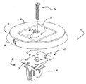
【図2】図1の留め具の展開透視図である。
【図3】スペーシング構造をより詳細に示す、図1の留め具の一部分の断面図である。
【図4】本発明の別の実施形態の開示に従って作られた留め具の透視図である。
【図5】クリップ構造をかなり詳細に示す、図1の留め具の一部分の正面図である
【図6】図1の留め具の側面図である。
【図7】図1の留め具の底面図である。
【図8】図5の線8−8に沿って切断した断面図である。
【図9】翼部材を捩る代替方式を示す、図8の断面図と類似の部分断面図である。
【図10】翼部材の先端部分の構造をかなり詳細に示す、図5の拡大部分を示す図である。
【図11】先端部分を形成する代替方式を示す、図10と類似の図である。
【図12】留め具の組み付け高さを減少させるために共通平面に配置されたフランジ部分及び底を有する、図1の類似の留め具の側面図である。
【図13】留め具が天井内張及び補助ハンドルを車両天井に固定するために使用される、図1の留め具に対する適用例を示す車両の展開透視図である。
【図14】完全組み付け状態にある留め具を示す、図13の線14−14に沿って切断した部分断面図である。
【図15】エアバッグ・モジュールとトリム・カバーとを車両本体構造に固定するために幾つかの留め具が使用される、図1と類似の留め具に対する適用例を示す車両の展開透視図である。
【図16】本発明の別の好ましい実施形態の開示に従って作られるクリップ構造の正面図である。
【図17】図16のクリップ構造の側面図である。
【図18】図16のクリップ構造の上面図である。
【図19】図16と類似のクリップ構造の正面図である。
【図20】図19のクリップ構造の側面図である。
【図21】本発明の別の好ましい実施形態の開示に従って作られたクリップ構造の正面図である。
【図22】図21のクリップ構造の側面図である。
【図23】図21のクリップ構造の上面図である。
【図24】留め具が内部トリム部品を車両本体構造に固定するために使用される、図21の留め具に対する適用例を示す展開透視図である。
【符号の説明】
10 弾性クリップ留め具
20 スペーシング構造
22 クリップ構造
30 第1フランジ部材
32 第2フランジ部材
34 第1フランジ部材30の外面
50 連結機構
52 溶接突起[0001]
Cross-reference of related applications
This application claims the benefit of US Provisional Application Serial No. 06 / 192,375 entitled “Fastening Assembly for Automotive Ceiling Linings” filed March 27, 2000, 2001 This is a continuation-in-part of U.S. patent application Ser. Another aspect of the present invention is described and claimed in a commonly assigned US patent application entitled “Resilient Clip Fastener” assigned to the present applicant.
[0002]
BACKGROUND OF THE INVENTION
The present invention relates generally to an elastic clip fastener, and more particularly to an elastic clip fastener that uses a plurality of wing members that secure a body portion of the elastic clip to a structure. More particularly, the present invention relates to an elastic clip fastener having a structure that utilizes a wing member that can withstand a relatively high release force while allowing the clip to be inserted with a relatively low insertion force. The invention also relates to an elastic clip fastener having a structure that responds in several ways to part-to-part variations between structures that are to be secured together.
[0003]
[Prior art]
Many current vehicles use elastic clips to secure various parts to the vehicle body. One such application relates to an auxiliary handle that is mounted on the ceiling of a vehicle above the door. Such an auxiliary handle not only provides a convenient point for the occupant to grip when getting into the vehicle, but also serves to allow the occupant to stabilize the upper body while driving the vehicle. In order to serve these functions, such a handle needs to withstand a load of over 250 pounds without disengaging from the fixing point of the vehicle sheet metal.
[0004]
In conventional procedures during vehicle assembly, the entire ceiling lining assembly is assembled in a single operation on the vehicle interior ceiling. In other words, the ceiling lining assembly with the already installed auxiliary handle and other ceiling mounting components is passed through the opening of either the windshield or backlight of the vehicle body on the assembly line, then It is fixed to the vehicle interior ceiling by the line operator. In order to accomplish this assembly operation, the ceiling lining assembly is usually provided with a corresponding reinforcement provided on the reinforced sheet metal member of the ceiling located around the periphery of the ceiling lining assembly as well as around the interior area of the ceiling lining. There are a number of fasteners that are designed to penetrate through holes. The line operator orients the ceiling lining assembly under the vehicle interior ceiling and presses fasteners into the various mounting holes in the reinforcing sheet metal member to secure the ceiling lining assembly to the vehicle ceiling responsible.
[0005]
For aesthetic reasons, ceiling lining fasteners are usually secured to the ceiling lining back in several ways so that they cannot be seen from inside the vehicle after the ceiling lining assembly is assembled. The Therefore, operators often blindly “feel” the location of the mounting holes with their fingers before pressing the fasteners into the holes from the side of the ceiling lining facing the opposite side. It becomes an obligation.
The slight misalignment that can occur between the fasteners and their corresponding mounting holes can prevent some fasteners from being properly installed and secured to the sheet metal. This situation is particularly problematic when handling fasteners for securing ceiling-mounted auxiliary handles. These fasteners generally need to withstand significantly higher detachment forces than fasteners that only work to hold the ceiling lining in place, so they are generally less effective by providing a significant increase in the required insertion force. There is less tolerance for misalignment problems that can greatly increase the likelihood of proper wearing. Under such circumstances, the detachment force that can be withstood before the fasteners detach from the sheet metal is significantly reduced.
[0006]
[Problems to be solved by the invention]
Accordingly, there remains a need in the art for an improved fastener that has a relatively low assembly force, a relatively high release force, and is relatively more tolerant of misalignment problems. Ideally, the fastener should be inexpensive to manufacture, reliable and easy to assemble. In addition, the fasteners must be particularly adapted to secure the structures together in a manner that minimizes the vibrations and associated noise problems often associated with such fasteners.
[0007]
[Means for Solving the Problems]
In one preferred form, the present invention provides an elastic clip that engages the structure. The elastic clip includes a flange portion, an insertion portion, and a holding portion. The flange portion is formed to abut against the outer surface of the structure. The insertion portion is connected to the flange portion and is configured to be inserted into a hole formed in the structure. The retaining portion is coupled to the insertion portion and includes at least three wing members. Each of the wing members is twisted about an associated axis and terminates at a tip portion configured to engage the structure.
[0008]
In another preferred form, the present invention provides an elastic clip that connects a first structure having a clamping tab to a second structure having a clip opening. The elastic clip includes a body portion and an engagement portion. The fuselage portion has a pair of flanges and first and second wing members, each of the wing members having a bottom portion coupled to an associated one of each flange. The first wing member is twisted about the first axis in a first direction, and the second wing member is twisted about the second axis in a first direction. Each of the wing members is inclined downwardly toward the bottom portion such that a portion of each wing member closest to the fuselage portion center axis extends above the associated portion of each wing member furthest from the fuselage portion center axis. Terminate at the tip. Each tip portion is formed to engage a first side of the structure to secure the elastic clip to the second structure. The engaging portion has a plurality of teeth extending inwardly toward the central axis of the fuselage portion and downwardly toward the bottom portion of the wing member. The plurality of teeth are arranged to engage the first structure.
Additional advantages and features of the present invention will become apparent from the following description and appended claims, taken in conjunction with the accompanying drawings.
[0009]
DETAILED DESCRIPTION OF THE INVENTION
Referring to FIGS. 1 and 2 with reference to the drawings, an elastic clip fastener made in accordance with the disclosure of the first embodiment of the present invention is indicated generally by the
[0010]
In the particular embodiment shown, the
[0011]
However, those skilled in the art will appreciate that the
[0012]
Referring back to FIGS. 2 and 3, the
[0013]
Referring back to FIG. 2, the
The
[0014]
With further reference to FIGS. 5-7, the
[0015]
In the particular embodiment shown, the
[0016]
The retaining portion 82 is shown to include a pair of
[0017]
Referring back to FIGS. 5-8, the
[0018]
Referring back to FIG. 5, each
[0019]
One usage for
[0020]
The tapered
[0021]
Further, the
Similarly, the variation in the distance between the
[0022]
Another example is shown in FIG. 15, where fastener 10a is illustrated in functional association with
[0023]
The threaded
[0024]
An additional fastener 10 a is used to secure the
[0025]
During deployment of the
[0026]
In FIGS. 16-18, a clip structure made in accordance with another preferred embodiment of the present invention is indicated generally by the
The
[0027]
In the particular embodiment illustrated, the
[0028]
The retaining
[0029]
Referring again to FIGS. 16-18, the
[0030]
The characteristics of
[0031]
An alternative embodiment of clip structure 522 designated by reference numeral 522 'is shown in FIGS. Clip structure 522 ′ is generally similar to clip structure 522 and includes a
[0032]
In FIGS. 21-23, a clip structure made in accordance with another preferred embodiment of the present invention is indicated generally by the
The
[0033]
The retaining portion 682 is made substantially the same as the
The
[0034]
Unlike
[0035]
[0036]
Using
[0037]
Although the invention has been described in the specification with reference to preferred embodiments and illustrated in the drawings, various modifications can be made to the elements without departing from the scope of the invention as defined in the claims. And those skilled in the art will appreciate that equivalents can be substituted. In addition, many modifications may be made to adapt a particular situation or material to the disclosure of the present invention without departing from its essential scope. Accordingly, the present invention should not be limited to the specific embodiments illustrated in the drawings and described in the specification as the best presently contemplated mode for carrying out the invention, but any embodiment is described above. And within the scope of the appended claims.
[Brief description of the drawings]
FIG. 1 is a perspective view of a fastener made in accordance with the present disclosure.
2 is an exploded perspective view of the fastener of FIG.
FIG. 3 is a cross-sectional view of a portion of the fastener of FIG. 1 showing the spacing structure in more detail.
FIG. 4 is a perspective view of a fastener made in accordance with the disclosure of another embodiment of the present invention.
FIG. 5 is a front view of a portion of the fastener of FIG. 1 showing the clip structure in greater detail.
6 is a side view of the fastener of FIG. 1. FIG.
7 is a bottom view of the fastener of FIG. 1. FIG.
8 is a cross-sectional view taken along line 8-8 of FIG.
9 is a partial cross-sectional view similar to the cross-sectional view of FIG. 8, showing an alternative method of twisting the wing member.
10 is an enlarged view of FIG. 5, showing the structure of the tip portion of the wing member in greater detail.
FIG. 11 is a view similar to FIG. 10 showing an alternative way of forming the tip portion.
12 is a side view of the similar fastener of FIG. 1 having a flange portion and a bottom disposed in a common plane to reduce the assembly height of the fastener.
13 is an exploded perspective view of a vehicle showing an application to the fastener of FIG. 1 where the fastener is used to secure the ceiling lining and the auxiliary handle to the vehicle ceiling.
14 is a partial cross-sectional view taken along line 14-14 of FIG. 13, showing the fastener in a fully assembled condition.
15 is an exploded perspective view of a vehicle showing an application to a fastener similar to FIG. 1 in which several fasteners are used to secure the airbag module and trim cover to the vehicle body structure. is there.
FIG. 16 is a front view of a clip structure made in accordance with the disclosure of another preferred embodiment of the present invention.
17 is a side view of the clip structure of FIG.
18 is a top view of the clip structure of FIG. 16. FIG.
FIG. 19 is a front view of a clip structure similar to FIG.
20 is a side view of the clip structure of FIG. 19. FIG.
FIG. 21 is a front view of a clip structure made in accordance with the disclosure of another preferred embodiment of the present invention.
22 is a side view of the clip structure of FIG. 21. FIG.
23 is a top view of the clip structure of FIG. 21. FIG.
24 is an exploded perspective view showing an application to the fastener of FIG. 21 where the fastener is used to secure an internal trim component to the vehicle body structure.
[Explanation of symbols]
10 Elastic clip fastener
20 Spacing structure
22 clip structure
30 First flange member
32 Second flange member
34 The outer surface of the
50 coupling mechanism
52 Welding protrusion
Claims (41)
開口(70、470)と、該開口(70、470)の回りに形成された螺旋リップ(72)とを有するフランジ(62、462)と、
前記フランジ(62、462)に連結されて、一対のほぼU字形状の部分(86、486)を有する胴体(60、460)を備え、前記一対のU字形状部分の各々は前記挿入軸線(42、442)を中にして対向するように配置されており、前記一対のU字形状部分(86、486)の各々において、挿入軸線方向にみて前記フランジ(62、462)とは反対側に位置する前記U字形状部分(86、486)の端部には、留め具開口(98、498)が形成されており、前記留め具開口(98、498)は、前記開口(70、470)に挿入されるねじ留め具(74)のための隙間を提供するように構成されており、
前記一対のU字形状部分(86、486)の各々には翼部材(100、500)が連結されており、該翼部材(100、500)の各々は、前記一対のU字形状部分(86、486)の各々に第1端部が連結され、前記フランジ(62、462)の方に延びて第2端部が自由端となっており、前記翼部材(100、500)は、前記第1端部と前記第2端部とが互いに角度をなすようにねじれた形状であり、前記第1端部の端面は、該端面の第1端部側面(120a)が該端面の反対側の第2端部側面(120b)に比較して垂直方向において前記フランジ(62、462)に近接するように、垂直方向にみて前記フランジ(62、462)に対して傾斜している、
ことを特徴とする留め具。A fastener (22, 422) inserted along an insertion axis (42, 442) into an opening (220) of a structure (208),
A flange (62, 462) having an opening (70, 470) and a helical lip (72) formed around the opening (70, 470);
Connected to the flanges (62, 462) and comprising a body (60, 460) having a pair of generally U-shaped portions (86, 486), each of the pair of U-shaped portions being connected to the insertion axis ( 42, 442) facing each other, and in each of the pair of U-shaped portions (86, 486) , on the opposite side to the flange (62, 462) in the insertion axis direction. At the end of the U-shaped portion located (86,486), fastener opening (98,498) is formed, said fastener opening (98,498), said opening (70,470) Configured to provide a clearance for a screw fastener (74) to be inserted into the
A wing member (100, 500) is connected to each of the pair of U-shaped portions (86, 486), and each of the wing members (100, 500) is connected to the pair of U-shaped portions (86). 486), a first end is connected to each of the first and second 486), extends toward the flanges (62, 462) and a second end is a free end, and the wing members (100, 500) are 1 has a shape in which the end portion and said second end portion is twisted at an angle to each other, the end faces of the first end, the first end portion side of the end face (120a) is on the opposite side of the end face so as to be close to the flange (62,462) in the vertical direction as compared to the second end side (120b), viewed in the vertical direction is inclined with respect to said flange (62,462),
A fastener characterized by that.
フランジ(462)と、
前記フランジ(462)に連結され、第1のほぼU字形状の部分(486)と第2のほぼU字形状の部分(486)とを有し、該第1のほぼU字形状の部分(486)と第2のほぼU字形状の部分(486)とは前記挿入軸線(442)を中にして対向するように配置されている、胴体(460)と、
前記第1のほぼU字形状の部分(486)に連結された第1の翼部材(500)と前記第2のほぼU字形状の部分(486)に連結された第2の翼部材(500)とを備え、
前記第1の翼部材(500)と前記第2の翼部材(500)の各々は、前記第1のほぼU字形状の部分(486)に連結された第1端部と該第1端部の反対側であって自由端面で終わっている第2端部とを有し、前記第1の翼部材(500)と前記第2の翼部材(500)の各々は、前記第1端部と前記第2端部が互いに角度をなすような形状であり、前記第2端部の前記自由端面は、該第2端部の端面の第1端部側面(520a)が該第2端部の端面の第2端部側面(520b)より垂直方向において前記フランジ(462)に対し近接するように、前記挿入軸線(442)にほぼ平行である垂直方向に前記フランジ(462)に対して傾斜している、
ことを特徴とする留め具。A fastener (422) inserted along an insertion axis (442) into an opening (220) of a structure (208),
A flange (462);
Connected to the flange (462) and having a first generally U-shaped portion (486) and a second generally U-shaped portion (486), the first generally U-shaped portion ( 486) and the second substantially U-shaped portion (486) are disposed to face each other with the insertion axis (442) in between, and a fuselage (460),
A first wing member (500) connected to the first substantially U-shaped portion (486) and a second wing member (500) connected to the second substantially U-shaped portion (486). )
Each of the first wing member (500) and the second wing member (500) includes a first end coupled to the first generally U-shaped portion (486) and the first end. each of a side opposite to have a second end portion terminating in a free end face, the first wing member (500) and the second wing member (500) includes a first end portion It said second end portion is shaped so as to form an angle to each other, wherein said free end face of the second end, the first end portion side of the end face of the second end portion (520a) of said second end portion Inclined with respect to the flange (462) in a vertical direction substantially parallel to the insertion axis (442) so as to be closer to the flange (462) in the vertical direction than the second end side surface (520b) of the end surface. ing,
A fastener characterized by that.
フランジ(462、462’)と、
前記フランジ(462、462’)に連結された胴体(460、460’)であって、第1の胴体部分(486、486’)と第2の胴体(486、486’)とを有し、該第1の胴体部分及び第2の胴体部分(486、486’)が、前記挿入軸線(442、442’)を中にして対向するように配置されている、前記胴体(460、460’)と、
前記第1の部分(486、486’)に連結された第1の翼部材(500)及び第2の翼部材(500)と、
前記第2の部分(486、486’)に連結された第3の翼部材(500)及び第4の翼部材(500)と、
を備え、
前記第1の翼部材(500)と前記第2の翼部材(500)と前記第3の翼部材(500)と前記第4の翼部材(500)のそれぞれは、前記第1の部分又は第2の部分(486、486’)の対応のものに連結された第1端部と該第1端部の反対側であって自由端面で終わっている第2端部とを有し、前記第1端部と前記第2端部とが互いに角度をなすような形状であり、前記第2端部の端面は、該第2端部の端面の第1端部側面(520a)が該第2端部の端面の第2端部側面(520b)より垂直方向において前記フランジ(462、462’)に対し近接するように、前記挿入軸線(442、442’)にほぼ平行である垂直方向に前記フランジ(462、462’)に対して傾斜しており、
前記第1及び第2の翼部材(500)の前記第2端部側面(520b)が相互に隣接しており、前記第3及び第4の翼部材(500)の前記第2端部側面(520b)が相互に隣接している、
ことを特徴とする留め具。A fastener (422) inserted along an insertion axis (442, 442 ') into an opening (220) of a structure (208),
Flanges (462, 462 ′);
A fuselage (460, 460 ') connected to the flange (462, 462'), having a first fuselage portion (486, 486 ') and a second fuselage (486, 486'); The fuselage (460, 460 '), wherein the first fuselage portion and the second fuselage portion (486, 486') are arranged to face each other with the insertion axis (442, 442 ') in between. When,
A first wing member (500) and a second wing member (500) coupled to the first portion (486, 486 ');
A third wing member (500) and a fourth wing member (500) connected to the second portion (486, 486 ') ;
With
Each of the first wing member (500), the second wing member (500), the third wing member (500), and the fourth wing member (500) includes the first portion or the second wing member (500). a opposite the first end coupled to one of the corresponding second portion (486,486 ') and said first end have a second end portion terminating in a free end face, the first first end and said second end portion is shaped so as to form an angle to each other, wherein the end face of the second end, said first end portion side of the end face of the second end portion (520a) is the second In the vertical direction substantially parallel to the insertion axis (442, 442 ′) so as to be closer to the flange (462, 462 ′) in the vertical direction than the second end side surface (520b) of the end face of the end portion. Inclined with respect to the flanges (462, 462 ′),
Said first and second of said second end side of the wing members (500) (520b) are adjacent to each other, the third and fourth of said second end side of the wing members (500) ( 520b) are adjacent to each other,
A fastener characterized by that.
フランジ(462、462’)と、
挿入部分(480、480’)と保持部分(482)を有する胴体(460、460’)を備え、前記挿入部分(480、480’)が第1の部材及び第2の部材(486、486’)を有し、前記第1の部材及び第2の部材(486、486’)のそれぞれが前記フランジ(462、462’)に連結された第1端部と第2端部とを有し、前記挿入部分(480、480’)が前記第1の部材(486、486’)に連結された第1及び第2の翼部材(500)と前記第2の部材(486、486’)に連結された第3及び第4の翼部材(500)とを有し、前記第1の翼部材(500)と前記第2の翼部材(500)と前記第3の翼部材(500)と前記第4の翼部材(500)とのそれぞれが、係合縁部を持ち、かつ、ねじれた形状を有し、前記第2の翼部材(500)から遠い側の、前記第1の翼部材(500)の前記係合縁部の端部側面(520a)が、前記挿入軸線(442、442’)に平行な方向において、前記フランジ(462、462’)に対して、前記第2の翼部材(500)に最も近い、前記第1の翼部材(500)の前記係合縁部の端部側面(520b)より、近くなるように、前記第1の翼部材(500)の前記係合縁部が前記フランジ(462、462’)に対して傾斜しており、
前記第1の翼部材と前記第2の翼部材との間に、前記挿入軸線(442、442’)を含み、該第1の翼部材と前記第2の翼部材とが鏡像となる第1平面を想定したとき、前記第2の翼部材(500)の前記係合縁部は、前記第1の翼部材(500)の前記係合縁部が対向する位置に配置される、
ことを特徴とする留め具。A fastener (422) inserted along an insertion axis (442, 442 ') into an opening (220) of a structure (208),
Flanges (462, 462 ′);
A body (460, 460 ′) having an insertion portion (480, 480 ′) and a holding portion (482) is provided, the insertion portion (480, 480 ′) being a first member and a second member (486, 486 ′). And each of the first member and the second member (486, 486 ′) has a first end and a second end connected to the flange (462, 462 ′), The insertion portion (480, 480 ′) is connected to the first and second wing members (500) connected to the first member (486, 486 ′) and the second member (486, 486 ′). Third and fourth wing members (500), and the first wing member (500), the second wing member (500), the third wing member (500), and the first wing member (500). each of the 4 wing member (500), Chi lifting the engagement edge, and has a twisted shape, the first The farther from the blade member (500), the side surface of the engagement edge portion of the first blade member (500) (520a) is, in a direction parallel to the insertion axis (442,442 '), Nearer to the flange (462, 462 ′) than the end side (520b) of the engagement edge of the first wing member (500) that is closest to the second wing member (500) The engagement edge of the first wing member (500) is inclined with respect to the flange (462, 462 ′),
The insertion axis (442, 442 ') is included between the first wing member and the second wing member, and the first wing member and the second wing member form a mirror image. when assuming the plane, the engagement edge portion of the second blade member (500), the engagement edge portion of the first blade member (500) is disposed opposite,
A fastener characterized by that.
Applications Claiming Priority (4)
| Application Number | Priority Date | Filing Date | Title |
|---|---|---|---|
| US19237500P | 2000-03-27 | 2000-03-27 | |
| US60/192375 | 2000-03-27 | ||
| US09/813592 | 2001-03-21 | ||
| US09/813,592 US7168138B2 (en) | 2000-03-27 | 2001-03-21 | Resilient clip fastener |
Publications (3)
| Publication Number | Publication Date |
|---|---|
| JP2002031118A JP2002031118A (en) | 2002-01-31 |
| JP2002031118A5 JP2002031118A5 (en) | 2008-05-08 |
| JP5001490B2 true JP5001490B2 (en) | 2012-08-15 |
Family
ID=26888025
Family Applications (1)
| Application Number | Title | Priority Date | Filing Date |
|---|---|---|---|
| JP2001134674A Expired - Lifetime JP5001490B2 (en) | 2000-03-27 | 2001-03-27 | Elastic clip fasteners |
Country Status (3)
| Country | Link |
|---|---|
| US (5) | US7168138B2 (en) |
| EP (1) | EP1138962A3 (en) |
| JP (1) | JP5001490B2 (en) |
Families Citing this family (76)
| Publication number | Priority date | Publication date | Assignee | Title |
|---|---|---|---|---|
| KR100437629B1 (en) * | 2001-05-23 | 2004-06-25 | (주)대한솔루션 | Assistant Handle Clip for Module Headliner of Automobile |
| US8627552B2 (en) * | 2001-06-25 | 2014-01-14 | Termax Corporation | Multicontact adaptive fastener clip |
| US7640634B2 (en) * | 2002-06-07 | 2010-01-05 | Termax Corporation | Ergonomic fastener |
| FR2829525B1 (en) * | 2001-09-13 | 2004-03-12 | Snecma Moteurs | ASSEMBLY OF SECTORS OF A TURBINE DISTRIBUTOR TO A CRANKCASE |
| WO2003046393A1 (en) * | 2001-11-21 | 2003-06-05 | Newfrey Llc | Plastic retaining clip for rib attachment |
| US6976292B2 (en) * | 2003-08-28 | 2005-12-20 | Newfrey Llc | Resilient clip fastener |
| DE202004014766U1 (en) * | 2004-09-20 | 2006-02-02 | Ramsauer, Dieter | Handle for mounting in a breakthrough |
| DE102004017188B4 (en) * | 2004-04-07 | 2006-08-24 | Key Safety Systems, Inc., Sterling Heights | Fastening element for airbag module |
| US7086125B2 (en) * | 2004-04-23 | 2006-08-08 | Newfrey Llc | Multiple stage assembly assist fastener |
| US9919674B2 (en) * | 2012-02-14 | 2018-03-20 | Termax Llc | Tethered fastener apparatus and method |
| US20070069191A1 (en) * | 2005-09-27 | 2007-03-29 | Black-Orange, Llc. | Silt and visual fence for erosion control |
| US20070144106A1 (en) * | 2005-12-16 | 2007-06-28 | Kirk Timothy S | Window installation clip |
| DE102006017878A1 (en) * | 2006-04-13 | 2007-10-25 | Newfrey Llc, Newark | mounting clip |
| DE502007003012D1 (en) * | 2006-04-26 | 2010-04-15 | Raymond A & Cie | FIXING DEVICE |
| DE102006023438A1 (en) * | 2006-05-18 | 2007-11-22 | Epcos Ag | Detachable sensor |
| US7419206B2 (en) * | 2006-07-28 | 2008-09-02 | Newfrey Llc | Interior trim fastener system |
| US7753402B2 (en) * | 2006-10-09 | 2010-07-13 | Key Safety Systems, Inc. | Air bag assembly and clip therefor |
| US20080142670A1 (en) * | 2006-12-13 | 2008-06-19 | Cvelbar Randall S | Devices, systems, and methods for mounting components |
| DE202007004549U1 (en) * | 2007-03-23 | 2007-06-28 | Takata-Petri Ag | Fastener to secure a vehicle airbag at a holder, for installation, has pliable sections to pass through the holder opening and reassert to bring limit surfaces against the holder opening to prevent withdrawal |
| FR2915539B1 (en) * | 2007-04-26 | 2009-07-24 | Attax Sarl | SYSTEM FOR ATTACHING TWO PIECES TO ONE ANOTHER |
| DE102007042484B3 (en) * | 2007-09-06 | 2009-01-08 | A. Raymond Et Cie | Device for fixing an attachment part to a support part comprises a manipulating structure having a guiding tongue placed on the free end of a front wall of a front wall arrangement and outwardly extending barrier wings |
| US7677653B2 (en) * | 2008-01-30 | 2010-03-16 | Nissan Technical Center North America, Inc. | Headliner retainer clip |
| WO2009099664A1 (en) * | 2008-02-07 | 2009-08-13 | Tinnerman Palnut Engineered Products | Deck clip |
| US8875357B2 (en) * | 2008-07-09 | 2014-11-04 | Tinnerman Palnut Engineered Products, Inc. | Clip |
| DE102008038925B4 (en) * | 2008-08-13 | 2015-09-24 | Autoliv Development Ab | Fastener and gas bag unit |
| US7871102B2 (en) * | 2008-09-16 | 2011-01-18 | Newfrey Llc | Air bag fastener assembly |
| FR2938026B1 (en) * | 2008-11-05 | 2013-01-18 | Saint Gobain | METHOD FOR MOUNTING A PIECE ON A PROFILE CORD, INTERMEDIATE FIXING DEVICE FOR ATTACHING A PIECE TO A PROFILE CORD AND USING THE SAME. |
| EP2356342B2 (en) * | 2008-11-17 | 2021-07-14 | ITW Metal Fasteners SL | Panel-fastening clips, especially for curtain or lateral airbags |
| HUE030808T2 (en) * | 2009-07-24 | 2017-05-29 | Pem Man Inc | Quick acting panel fastener |
| ES2356761B1 (en) * | 2009-07-31 | 2012-02-29 | Illinois Tools Works Inc. | ROOF CLIP FOR FIXING ACCESSORIES TO VEH� CULOS PANELS. |
| US8622490B2 (en) * | 2009-10-22 | 2014-01-07 | Mtn Products, Inc. | Panel attachment for water cooler |
| CN102656376B (en) | 2009-11-04 | 2015-04-01 | 伊利诺斯工具制品有限公司 | Removable and reusable quick nut |
| DE102009054861A1 (en) * | 2009-12-17 | 2011-06-22 | Hilti Aktiengesellschaft | Fastening device for attachments to mounting rails |
| DE102010008458A1 (en) * | 2010-02-18 | 2011-09-08 | A. Raymond Et Cie | fastening device |
| JP5611716B2 (en) * | 2010-08-16 | 2014-10-22 | 株式会社屋根技術研究所 | Plate module fixing structure |
| DE202010012226U1 (en) * | 2010-09-06 | 2011-12-07 | Dieter Ramsauer | fastening device |
| JP5558322B2 (en) * | 2010-11-25 | 2014-07-23 | 大和化成工業株式会社 | clip |
| US8756870B2 (en) * | 2011-06-03 | 2014-06-24 | A. Raymond Et Cie | Roof clamp |
| US8729388B2 (en) | 2011-11-01 | 2014-05-20 | Hubbell Incorporated | Mounting member for an electrical box assembly |
| US8674219B2 (en) | 2011-11-01 | 2014-03-18 | Hubbell Incorporated | Mounting clip for electrical device |
| US8800120B2 (en) | 2012-04-27 | 2014-08-12 | Newfrey Llc | High retention fastener |
| US8733718B2 (en) * | 2012-05-10 | 2014-05-27 | Peter A. CORSI | Non-invasive roof mounting adaptor and method for installing same |
| US9131787B2 (en) * | 2012-06-29 | 2015-09-15 | Process Retail Group, Inc. | Merchandising unit and system |
| US9879779B2 (en) * | 2013-03-08 | 2018-01-30 | Denso International America, Inc. | Self-retaining gasket |
| US9046178B2 (en) * | 2013-03-08 | 2015-06-02 | Denso International America, Inc. | Self-retaining gasket and fastener retainer |
| DE102013219957A1 (en) | 2013-10-01 | 2015-04-16 | Bayerische Motoren Werke Aktiengesellschaft | Method for fastening a first component to a second component of a motor vehicle and fastening arrangement of a first component to a second component of a motor vehicle |
| KR101582891B1 (en) | 2014-10-24 | 2016-01-08 | (주)대한솔루션 | Fixture for vehicle |
| US9440596B2 (en) * | 2014-11-20 | 2016-09-13 | Ford Global Technologies, Llc | Retention clip for interior vehicle components |
| US11031904B2 (en) | 2014-12-11 | 2021-06-08 | A.K. Stamping Company, Inc. | Grounding clamps |
| US9580114B2 (en) * | 2015-03-13 | 2017-02-28 | GM Global Technology Operations LLC | Clip and coupling assembly |
| US9637079B2 (en) * | 2015-04-28 | 2017-05-02 | Toyota Motor Engineering & Manufacturing North America, Inc. | Datum to provide additional retention force |
| US10006479B2 (en) * | 2015-08-20 | 2018-06-26 | Termax Llc | Fastener clip assembly with funnel guide |
| US9649993B1 (en) * | 2015-08-20 | 2017-05-16 | Termax Corporation | One step assembly fastener clip |
| US9968720B2 (en) | 2016-04-11 | 2018-05-15 | CorWave SA | Implantable pump system having an undulating membrane |
| US10166319B2 (en) | 2016-04-11 | 2019-01-01 | CorWave SA | Implantable pump system having a coaxial ventricular cannula |
| US10507771B2 (en) | 2016-04-18 | 2019-12-17 | Ford Global Technologies, Llc | W-shaped winged spring clip |
| DE102016107357A1 (en) * | 2016-04-20 | 2017-10-26 | Witte Automotive Gmbh | Device for compensating tolerances |
| JP6498151B2 (en) * | 2016-05-31 | 2019-04-10 | 株式会社ニフコ | Grounding clip |
| CN107763037B (en) * | 2016-08-19 | 2021-03-16 | 福特环球技术公司 | Conical clamp |
| US9841041B1 (en) | 2016-09-01 | 2017-12-12 | Ford Global Technologies, Llc | W-shaped winged spring clip with integral 4-way locator |
| US10100857B2 (en) | 2016-09-01 | 2018-10-16 | Ford Global Technologies, Llc | W-shaped winged spring clip with at least one reinforcing gusset |
| US10077790B2 (en) | 2016-12-22 | 2018-09-18 | Ford Global Technologies, Llc | Spring clip with three cantilevered bars and integral 4-way locator |
| US10093157B2 (en) * | 2017-03-03 | 2018-10-09 | Honda Motor Co., Ltd. | Two-stage sun visor mounting system and method |
| AU2018242620B2 (en) * | 2017-03-31 | 2023-11-16 | CorWave SA | Implantable pump system having a rectangular membrane |
| US10436233B2 (en) | 2017-09-07 | 2019-10-08 | Ford Global Technologies, Llc | Spring clip with frangible features indicating correct installation |
| FR3073578B1 (en) | 2017-11-10 | 2019-12-13 | Corwave | FLUID CIRCULATOR WITH RINGING MEMBRANE |
| US10188779B1 (en) | 2017-11-29 | 2019-01-29 | CorWave SA | Implantable pump system having an undulating membrane with improved hydraulic performance |
| USD874913S1 (en) * | 2018-06-19 | 2020-02-11 | Illinois Tool Works Inc. | Nut retainer |
| EP3830431B1 (en) | 2018-07-27 | 2023-12-06 | Illinois Tool Works, Inc. | Fastener assembly and method |
| US11680678B2 (en) | 2018-12-03 | 2023-06-20 | Peter A. CORSI | Non-invasive roof mounting adapter plate and method for installing same |
| US10799625B2 (en) | 2019-03-15 | 2020-10-13 | CorWave SA | Systems and methods for controlling an implantable blood pump |
| US11359383B2 (en) * | 2019-04-23 | 2022-06-14 | Omg, Inc. | Hidden fastener assembly for attaching grooved deck members |
| US11692581B2 (en) * | 2019-08-22 | 2023-07-04 | Illinois Tool Works Inc. | Box nut retainer |
| USD904865S1 (en) * | 2019-08-23 | 2020-12-15 | Illinois Tool Works Inc. | Nut retainer |
| USD904866S1 (en) * | 2019-08-23 | 2020-12-15 | Illinois Tool Works Inc. | Nut retainer |
| US11191946B2 (en) | 2020-03-06 | 2021-12-07 | CorWave SA | Implantable blood pumps comprising a linear bearing |
Family Cites Families (85)
| Publication number | Priority date | Publication date | Assignee | Title |
|---|---|---|---|---|
| US1873871A (en) | 1931-01-14 | 1932-08-23 | United Carr Fastener Corp | Snap fastener stud and installation thereof |
| US2032315A (en) | 1933-06-13 | 1936-02-25 | United Carr Fastener Corp | Rotary operative fastener installation and fastener for the same |
| US2217781A (en) * | 1935-11-02 | 1940-10-15 | William R Wiley | Attaching clip for metal moldings |
| US2181966A (en) * | 1937-07-08 | 1939-12-05 | Gen Motors Corp | Fastening device |
| US2198186A (en) * | 1937-07-09 | 1940-04-23 | Tinnerman Products Inc | Clip for moldings and the like |
| GB571428A (en) | 1943-07-22 | 1945-08-23 | Tinnerman Products Inc | Improvements relating to screw and nut fastenings |
| US2509192A (en) | 1947-06-19 | 1950-05-23 | Illinois Tool Works | Drive fastener |
| US2618998A (en) | 1949-11-03 | 1952-11-25 | Illinois Tool Works | Molding clip |
| US2692414A (en) * | 1952-05-08 | 1954-10-26 | Illinois Tool Works | Snap-in stud fastener |
| GB744172A (en) * | 1953-01-21 | 1956-02-01 | Carr Fastener Co Ltd | Improvements in and relating to fastening devices |
| GB836121A (en) | 1956-03-08 | 1960-06-01 | Ft Products Ltd | Improvements relating to fasteners |
| US2885754A (en) * | 1956-12-05 | 1959-05-12 | Illinois Tool Works | Snap-in fastener |
| US3034615A (en) * | 1957-06-24 | 1962-05-15 | United Carr Fastener Corp | Molding fastener |
| US2961723A (en) * | 1957-12-06 | 1960-11-29 | Illinois Tool Works | Molding clip |
| US2959259A (en) | 1958-09-15 | 1960-11-08 | Gen Motors Corp | Fastener device |
| US2964814A (en) * | 1958-12-29 | 1960-12-20 | United Carr Fastener Corp | Fastener devices for securing a channel or like shape moulding strip to a support |
| US3310929A (en) | 1964-07-13 | 1967-03-28 | Gen Motors Corp | Molding and clip assembly |
| US3400743A (en) | 1965-05-18 | 1968-09-10 | Tinnerman Products Inc | Sheet metal fastener with resilient arms |
| FR1477535A (en) | 1966-02-08 | 1967-04-21 | Anciens Etablissements B A C | Fastening clip, in particular for a guide slide for a motor vehicle window |
| FR1477353A (en) | 1966-04-26 | 1967-04-14 | Uhren Und Maschinen Fabrik Ruh | Alarm clock with warning device for short intervals of time |
| US3441986A (en) * | 1967-08-31 | 1969-05-06 | Robin Products Co | Fastening clip |
| US3486158A (en) | 1967-09-29 | 1969-12-23 | Illinois Tool Works | Grounding clip |
| US3486202A (en) * | 1968-05-16 | 1969-12-30 | Illinois Tool Works | Snap-in fastener |
| JPS4830772Y1 (en) * | 1969-07-19 | 1973-09-19 | ||
| SE401653B (en) | 1972-06-21 | 1978-05-22 | Springfix Befestigungstechnik | MOUNTING CLAMP FOR MOLDINGS WITH T-SHAPE ROCK |
| US3871430A (en) * | 1973-10-26 | 1975-03-18 | Usm Corp | Retainer clip |
| US3939752A (en) | 1974-12-23 | 1976-02-24 | Illinois Tool Works Inc. | Fastener structure |
| DE2648467A1 (en) | 1976-10-26 | 1978-04-27 | Springfix Befestigungstechnik | Bolt fixture for motor vehicle bumper - has U-form clamp strip retained in bumper plate aperture by sprung integral arms |
| US4383716A (en) * | 1979-03-30 | 1983-05-17 | Ni Industries Inc. | Wheel trim retention system |
| US4300865A (en) | 1979-07-11 | 1981-11-17 | Trw Inc. | Blind clip fastener |
| DE3041610C2 (en) * | 1980-11-01 | 1986-10-02 | Wickmann-Werke GmbH, 5810 Witten | Holder for electrotechnical components |
| US4814979A (en) * | 1981-04-01 | 1989-03-21 | Teradata Corporation | Network to transmit prioritized subtask pockets to dedicated processors |
| US4402118A (en) | 1981-09-28 | 1983-09-06 | Usm Corporation | Clip for securing a panel to a support |
| US4595325A (en) | 1984-09-28 | 1986-06-17 | Eaton Corporation | Self-locking prevailing torque fastener |
| JPS6217410A (en) | 1985-07-15 | 1987-01-26 | 株式会社ニフコ | Fastener for fixing two panel in contact surface manner |
| US4630338A (en) * | 1985-12-19 | 1986-12-23 | Usm Corporation | Molding clip |
| US5753853A (en) * | 1986-02-20 | 1998-05-19 | Kenrich Petrochemicals, Inc. | Solid propellant with titanate bonding agent |
| US4644612A (en) | 1986-05-30 | 1987-02-24 | Usm Corporation | Panel retainer |
| JPS6391710U (en) * | 1986-12-03 | 1988-06-14 | ||
| JPH0310408Y2 (en) | 1987-02-28 | 1991-03-14 | ||
| US4913484A (en) | 1988-06-10 | 1990-04-03 | United Technologies Automotive, Inc. | Headliner and sunshade fastener |
| US4981323A (en) | 1988-06-10 | 1991-01-01 | United Technologies Automotive, Inc. | Assist strap for a modular headliner |
| US4893866A (en) | 1988-06-10 | 1990-01-16 | United Technologies Automotive Inc. | Motor vehicle body structure for receiving snap-fit modular headliner fasteners |
| US5105521A (en) | 1988-06-10 | 1992-04-21 | United Technologies Automotive, Inc. | Method of assembling modular headliner to a vehicle by snap-fitting |
| US4902068A (en) | 1988-06-10 | 1990-02-20 | United Technologies Automotive, Inc. | Modular headliner assembly |
| US5269060A (en) | 1988-06-10 | 1993-12-14 | United Technologies Automotive, Inc. | Method of aligning and installing an automobile headliner by a previously attached sunshade assembly |
| US4844533A (en) | 1988-06-10 | 1989-07-04 | United Technologies Automotive, Inc. | Front lamp module and sunshade supports for modular headliner |
| US4981322A (en) | 1988-06-10 | 1991-01-01 | United Technologies Corporation, Inc. | Assist strap for a motor vehicle |
| US4925351A (en) | 1989-03-21 | 1990-05-15 | Trw, Inc. | Push-in fastener clip |
| US5056853A (en) | 1989-08-16 | 1991-10-15 | Prince Corporation | Snap-in visor mount |
| US4989911A (en) | 1989-08-16 | 1991-02-05 | Prince Corporation | Snap-in visor mount |
| US5061005A (en) | 1989-08-16 | 1991-10-29 | Prince Corporation | Snap-in visor mount |
| US5251467A (en) * | 1992-09-08 | 1993-10-12 | Loctec Corporation | Front-installed cam lock |
| US5759004A (en) * | 1993-04-20 | 1998-06-02 | Panduit Corp. | MLT bent leg pushmount |
| US5367751A (en) * | 1993-04-30 | 1994-11-29 | Chrysler Corporation | Panel locator and attachment apparatus |
| US5451022A (en) | 1994-02-22 | 1995-09-19 | Wayne State University | Mounting bracket for a sun visor |
| US5857735A (en) | 1994-06-20 | 1999-01-12 | Irausa Ingenieria, S.A. | Self-supporting roof with built-in fittings directly mountable upon vehicle roofs |
| US5542158A (en) | 1994-09-12 | 1996-08-06 | Emhart Inc. | Grommet fastener assembly for automobiles |
| US5632061A (en) | 1994-09-29 | 1997-05-27 | Prince Corporation | Assist strap |
| US5499854A (en) | 1994-12-06 | 1996-03-19 | Crotty Corporation | Mounting bracket assembly for a vehicle sunshade and method of installing same in a vehicle |
| US5560575A (en) | 1995-02-21 | 1996-10-01 | Trw Inc. | Support and releasable fastener assembly |
| US5636891A (en) * | 1995-06-07 | 1997-06-10 | Prince Corporation | Adjustable fastener |
| US5758987A (en) | 1995-09-18 | 1998-06-02 | Southco, Inc. | Snap-in fastener for flush-mounted panels |
| US5752853A (en) | 1995-12-13 | 1998-05-19 | United Technologies Automotive Systems, Inc. | Snap-in visor mount and electrical connectors for visor mounts |
| JP3160197B2 (en) | 1995-12-27 | 2001-04-23 | 本田技研工業株式会社 | Vehicle interior materials |
| JP3750695B2 (en) * | 1996-01-08 | 2006-03-01 | 株式会社ニフコ | Plate connector |
| US6212550B1 (en) * | 1997-01-21 | 2001-04-03 | Motorola, Inc. | Method and system in a client-server for automatically converting messages from a first format to a second format compatible with a message retrieving device |
| US6170017B1 (en) * | 1997-05-08 | 2001-01-02 | International Business Machines Corporation | Method and system coordinating actions among a group of servers |
| US5852849A (en) | 1997-06-24 | 1998-12-29 | Pinnacle Products Of Wisconsin, Inc. | Bib holder for holding dental bibs |
| US5774949A (en) | 1997-08-27 | 1998-07-07 | Eaton Corporation | Trim clip |
| WO1999012103A2 (en) * | 1997-09-05 | 1999-03-11 | Sun Microsystems, Inc. | Scalable shared memory multiprocessor system |
| US6003928A (en) | 1997-10-14 | 1999-12-21 | Lear Automotive Dearborn, Inc. | Interior trim attachment apparatus for an automotive vehicle |
| US5991976A (en) | 1997-12-05 | 1999-11-30 | Prince Corporation | Assist handle mounting plate |
| US5919019A (en) | 1998-01-20 | 1999-07-06 | California Industrial Products, Inc. | Mid-panel nut |
| US5873690A (en) * | 1998-01-22 | 1999-02-23 | Eaton Corporation | Thread nut expansion fastener |
| US6101686A (en) | 1998-03-17 | 2000-08-15 | Daimlerchrysler Corporation | Interior trim spring clip |
| US6141837A (en) * | 1999-02-26 | 2000-11-07 | Wisniewski; David M. | EDIAS clip for securing an interior molding to a vehicle frame |
| US6095734A (en) * | 1999-09-21 | 2000-08-01 | Transtechnology Corp. | Pushnut |
| US6179366B1 (en) * | 1999-12-14 | 2001-01-30 | General Motors Corporation | Sunshade mounting clip assembly |
| US6527471B2 (en) * | 2000-01-19 | 2003-03-04 | Termax Corporation | Sealing spring fastener with closed cavity |
| US6381811B2 (en) * | 2000-04-26 | 2002-05-07 | Termax Corporation | Sealing spring fastener with hermetically closed cavity |
| US7028299B1 (en) * | 2000-06-30 | 2006-04-11 | Intel Corporation | Task-based multiprocessing system |
| US6718599B2 (en) | 2001-06-25 | 2004-04-13 | Termax Corporation | Spring fastener with ergonomically balanced removal to insertion force ratio |
| US6745440B2 (en) | 2001-07-31 | 2004-06-08 | Eustathios Vassiliou Revocable Trust | Increased holding power spring fasteners |
| US6691380B2 (en) | 2001-07-31 | 2004-02-17 | Eustathios Vassiliou Revocable Trust | Fasteners of increased holding power |
-
2001
- 2001-03-21 US US09/813,592 patent/US7168138B2/en not_active Expired - Lifetime
- 2001-03-26 EP EP01302742A patent/EP1138962A3/en not_active Withdrawn
- 2001-03-27 JP JP2001134674A patent/JP5001490B2/en not_active Expired - Lifetime
-
2003
- 2003-07-28 US US10/628,708 patent/US6857168B2/en not_active Expired - Lifetime
-
2006
- 2006-08-31 US US11/514,054 patent/US7318256B2/en not_active Expired - Lifetime
- 2006-08-31 US US11/514,069 patent/US7320157B2/en not_active Expired - Lifetime
- 2006-08-31 US US11/514,052 patent/US7213304B2/en not_active Expired - Lifetime
Also Published As
| Publication number | Publication date |
|---|---|
| US20060288545A1 (en) | 2006-12-28 |
| US7168138B2 (en) | 2007-01-30 |
| US20040040124A1 (en) | 2004-03-04 |
| US7318256B2 (en) | 2008-01-15 |
| US6857168B2 (en) | 2005-02-22 |
| US7213304B2 (en) | 2007-05-08 |
| US20020007537A1 (en) | 2002-01-24 |
| EP1138962A3 (en) | 2002-11-06 |
| US20060288544A1 (en) | 2006-12-28 |
| US7320157B2 (en) | 2008-01-22 |
| JP2002031118A (en) | 2002-01-31 |
| EP1138962A2 (en) | 2001-10-04 |
| US20060288543A1 (en) | 2006-12-28 |
Similar Documents
| Publication | Publication Date | Title |
|---|---|---|
| JP5001490B2 (en) | Elastic clip fasteners | |
| US7832693B2 (en) | Fastener | |
| US7120971B2 (en) | Low insertion effort u-base retainer | |
| JP3715232B2 (en) | Pillar garnish fastening structure | |
| US6883828B2 (en) | Vehicle body structure with head protecting airbag | |
| JP4894102B2 (en) | Attachment structure of cloth sheet to vehicle body | |
| JP2005308221A (en) | Multi-stage assembly auxiliary fastener | |
| US20010032377A1 (en) | Resilient clip fastener | |
| US20010046426A1 (en) | Resilient clip fastener | |
| US20050046157A1 (en) | Passenger air bag module with cover coupling mechanism | |
| JP2002067856A (en) | Mounting structure of airbag incorporated pillar garnish | |
| US7188860B2 (en) | Airbag apparatus for front passenger seat | |
| US10131290B2 (en) | Removable and serviceable twist lock assembly clip for blind installation | |
| KR102529461B1 (en) | Carpet and car mat fixing device for vehicle and mounting method thereof | |
| JP4108494B2 (en) | Finisher structure for vehicles | |
| JPH1130214A (en) | Clip | |
| JP3564986B2 (en) | Automotive belt retractor mounting structure | |
| JP4259702B2 (en) | Mounting structure for interior parts | |
| JP4408588B2 (en) | Shift lever boot mounting structure | |
| JP3960835B2 (en) | Device for mounting vehicle interior parts to trim board | |
| JP2002012122A (en) | Air bag device | |
| JPH0885382A (en) | Fitting device of lid body | |
| JP2001055070A (en) | Structure of operation lever housing part in seat cushion | |
| JP4245935B2 (en) | Assist grip mounting structure | |
| JPH0617631Y2 (en) | Automotive seat mounting structure |
Legal Events
| Date | Code | Title | Description |
|---|---|---|---|
| A521 | Request for written amendment filed |
Free format text: JAPANESE INTERMEDIATE CODE: A523 Effective date: 20080326 |
|
| A621 | Written request for application examination |
Free format text: JAPANESE INTERMEDIATE CODE: A621 Effective date: 20080326 |
|
| A131 | Notification of reasons for refusal |
Free format text: JAPANESE INTERMEDIATE CODE: A131 Effective date: 20110630 |
|
| A601 | Written request for extension of time |
Free format text: JAPANESE INTERMEDIATE CODE: A601 Effective date: 20110930 |
|
| A602 | Written permission of extension of time |
Free format text: JAPANESE INTERMEDIATE CODE: A602 Effective date: 20111005 |
|
| A601 | Written request for extension of time |
Free format text: JAPANESE INTERMEDIATE CODE: A601 Effective date: 20111031 |
|
| A602 | Written permission of extension of time |
Free format text: JAPANESE INTERMEDIATE CODE: A602 Effective date: 20111104 |
|
| A521 | Request for written amendment filed |
Free format text: JAPANESE INTERMEDIATE CODE: A523 Effective date: 20111114 |
|
| TRDD | Decision of grant or rejection written | ||
| A01 | Written decision to grant a patent or to grant a registration (utility model) |
Free format text: JAPANESE INTERMEDIATE CODE: A01 Effective date: 20120510 |
|
| A01 | Written decision to grant a patent or to grant a registration (utility model) |
Free format text: JAPANESE INTERMEDIATE CODE: A01 |
|
| A61 | First payment of annual fees (during grant procedure) |
Free format text: JAPANESE INTERMEDIATE CODE: A61 Effective date: 20120518 |
|
| R150 | Certificate of patent or registration of utility model |
Ref document number: 5001490 Country of ref document: JP Free format text: JAPANESE INTERMEDIATE CODE: R150 Free format text: JAPANESE INTERMEDIATE CODE: R150 |
|
| FPAY | Renewal fee payment (event date is renewal date of database) |
Free format text: PAYMENT UNTIL: 20150525 Year of fee payment: 3 |
|
| R250 | Receipt of annual fees |
Free format text: JAPANESE INTERMEDIATE CODE: R250 |
|
| R250 | Receipt of annual fees |
Free format text: JAPANESE INTERMEDIATE CODE: R250 |
|
| R250 | Receipt of annual fees |
Free format text: JAPANESE INTERMEDIATE CODE: R250 |
|
| R250 | Receipt of annual fees |
Free format text: JAPANESE INTERMEDIATE CODE: R250 |
|
| R250 | Receipt of annual fees |
Free format text: JAPANESE INTERMEDIATE CODE: R250 |
|
| R250 | Receipt of annual fees |
Free format text: JAPANESE INTERMEDIATE CODE: R250 |
|
| EXPY | Cancellation because of completion of term |