JP4997422B2 - Housing with pedestrian protection that can be fixed to a car - Google Patents
Housing with pedestrian protection that can be fixed to a car Download PDFInfo
- Publication number
- JP4997422B2 JP4997422B2 JP2009510277A JP2009510277A JP4997422B2 JP 4997422 B2 JP4997422 B2 JP 4997422B2 JP 2009510277 A JP2009510277 A JP 2009510277A JP 2009510277 A JP2009510277 A JP 2009510277A JP 4997422 B2 JP4997422 B2 JP 4997422B2
- Authority
- JP
- Japan
- Prior art keywords
- housing
- housing part
- housing according
- cross
- section
- Prior art date
- Legal status (The legal status is an assumption and is not a legal conclusion. Google has not performed a legal analysis and makes no representation as to the accuracy of the status listed.)
- Expired - Fee Related
Links
Images


Classifications
-
- B—PERFORMING OPERATIONS; TRANSPORTING
- B60—VEHICLES IN GENERAL
- B60R—VEHICLES, VEHICLE FITTINGS, OR VEHICLE PARTS, NOT OTHERWISE PROVIDED FOR
- B60R21/00—Arrangements or fittings on vehicles for protecting or preventing injuries to occupants or pedestrians in case of accidents or other traffic risks
- B60R21/34—Protecting non-occupants of a vehicle, e.g. pedestrians
-
- F—MECHANICAL ENGINEERING; LIGHTING; HEATING; WEAPONS; BLASTING
- F02—COMBUSTION ENGINES; HOT-GAS OR COMBUSTION-PRODUCT ENGINE PLANTS
- F02M—SUPPLYING COMBUSTION ENGINES IN GENERAL WITH COMBUSTIBLE MIXTURES OR CONSTITUENTS THEREOF
- F02M35/00—Combustion-air cleaners, air intakes, intake silencers, or induction systems specially adapted for, or arranged on, internal-combustion engines
- F02M35/02—Air cleaners
- F02M35/04—Air cleaners specially arranged with respect to engine, to intake system or specially adapted to vehicle; Mounting thereon ; Combinations with other devices
-
- F—MECHANICAL ENGINEERING; LIGHTING; HEATING; WEAPONS; BLASTING
- F02—COMBUSTION ENGINES; HOT-GAS OR COMBUSTION-PRODUCT ENGINE PLANTS
- F02M—SUPPLYING COMBUSTION ENGINES IN GENERAL WITH COMBUSTIBLE MIXTURES OR CONSTITUENTS THEREOF
- F02M35/00—Combustion-air cleaners, air intakes, intake silencers, or induction systems specially adapted for, or arranged on, internal-combustion engines
- F02M35/16—Combustion-air cleaners, air intakes, intake silencers, or induction systems specially adapted for, or arranged on, internal-combustion engines characterised by use in vehicles
- F02M35/161—Arrangement of the air intake system in the engine compartment, e.g. with respect to the bonnet or the vehicle front face
-
- B—PERFORMING OPERATIONS; TRANSPORTING
- B60—VEHICLES IN GENERAL
- B60R—VEHICLES, VEHICLE FITTINGS, OR VEHICLE PARTS, NOT OTHERWISE PROVIDED FOR
- B60R21/00—Arrangements or fittings on vehicles for protecting or preventing injuries to occupants or pedestrians in case of accidents or other traffic risks
- B60R21/34—Protecting non-occupants of a vehicle, e.g. pedestrians
- B60R2021/343—Protecting non-occupants of a vehicle, e.g. pedestrians using deformable body panel, bodywork or components
-
- Y—GENERAL TAGGING OF NEW TECHNOLOGICAL DEVELOPMENTS; GENERAL TAGGING OF CROSS-SECTIONAL TECHNOLOGIES SPANNING OVER SEVERAL SECTIONS OF THE IPC; TECHNICAL SUBJECTS COVERED BY FORMER USPC CROSS-REFERENCE ART COLLECTIONS [XRACs] AND DIGESTS
- Y10—TECHNICAL SUBJECTS COVERED BY FORMER USPC
- Y10T—TECHNICAL SUBJECTS COVERED BY FORMER US CLASSIFICATION
- Y10T292/00—Closure fasteners
- Y10T292/08—Bolts
- Y10T292/1043—Swinging
- Y10T292/1044—Multiple head
- Y10T292/1045—Operating means
- Y10T292/1047—Closure
-
- Y—GENERAL TAGGING OF NEW TECHNOLOGICAL DEVELOPMENTS; GENERAL TAGGING OF CROSS-SECTIONAL TECHNOLOGIES SPANNING OVER SEVERAL SECTIONS OF THE IPC; TECHNICAL SUBJECTS COVERED BY FORMER USPC CROSS-REFERENCE ART COLLECTIONS [XRACs] AND DIGESTS
- Y10—TECHNICAL SUBJECTS COVERED BY FORMER USPC
- Y10T—TECHNICAL SUBJECTS COVERED BY FORMER US CLASSIFICATION
- Y10T292/00—Closure fasteners
- Y10T292/08—Bolts
- Y10T292/1043—Swinging
- Y10T292/1075—Operating means
- Y10T292/1082—Motor
Description
本発明は、自動車の構成部品に固定可能なハウジングに関し、特に第1ハウジング部品とこれに結合可能な第2ハウジング部品とを備えた形式のハウジングに関する。ここで、自動車の構成部品とは、例えば車体、エンジン、或いはその他のアッセンブリ部材が該当し、従って第1と第2のハウジング部品は、結合状態においてそれらの間に中空スペースを形成するのが一般的である。 The present invention relates to a housing that can be fixed to a component of an automobile, and more particularly, to a housing of a type including a first housing part and a second housing part that can be coupled to the first housing part. Here, the automobile component corresponds to, for example, a vehicle body, an engine, or another assembly member, and therefore, the first and second housing components generally form a hollow space between them in a coupled state. Is.
この種のハウジングは例えばエアフィルタハウジングとして利用されており、一般的にはエアフィルタエレメントを収容するために自動車のエンジンルーム内におけるエンジンの上方でエンジンカバーの下部に配置されている。 This type of housing is used, for example, as an air filter housing, and is generally disposed above the engine in the engine room of the automobile and below the engine cover to accommodate the air filter element.
従来から用いられているこの種のハウジングは剛構造であり、人身事故の際にはハウジングを覆っている車体部分が剛構造のハウジングに衝合するときに歩行者に怪我を負わせる結果となるおそれがあった。 Conventionally this type of housing has a rigid structure, and in the event of a personal injury, the body part that covers the housing may result in injury to the pedestrian when it hits the rigid structure housing. was there.
このため、新たな法律の規定では、歩行者保護性能及び衝突時の構造特性に関して、歩行者へ衝撃を与える場合に自動車の特定部分、特にエンジンルームに対して或る限定的な可撓性を持たせることが要求されている。従って、今後新規に開発される自動車構造システムでは、車体内部に配置される例えばエアフィルタハウジング等もこ規定に沿った「歩行者保護型」のハウジング形式に統一する必要がある。 For this reason, the new legislation provides certain limited flexibility for certain parts of the car, especially the engine compartment, when impacting pedestrians, with regard to pedestrian protection performance and structural characteristics during a collision. It is required to have it. Accordingly, in a newly developed automobile structure system in the future, it is necessary to unify the “pedestrian protection type” housing type, for example, the air filter housing disposed inside the vehicle body in accordance with this regulation.
本発明の課題は、衝突時における歩行者保護のための新たな法律規程を満たすように冒頭に記載した形式のハウジングを改良することにある。即ち、本発明は、衝突時にハウジングが装着位置、即ち正規位置から予め定められた様式で離脱し、その際に好ましくは衝撃エネルギーも吸収するという基本性能を満たすことの可能なハウジングを提供しようとするものである。 An object of the present invention is to improve a housing of the type described at the beginning so as to satisfy new legal regulations for pedestrian protection in the event of a collision. That is, the present invention aims to provide a housing capable of satisfying the basic performance that the housing is detached from the mounting position, that is, the normal position in a predetermined manner at the time of collision, and preferably absorbs impact energy at that time. To do.
この課題は、本発明によれば、冒頭に述べた形式のハウジングにおいて第1ハウジング部品に縦長支持要素を設け、縦長支持要素は第1ハウジング部品側の基端部で第1ハウジング部品に結合しておくと共に該基端部から軸方向に離れた先端部側に主作用横断面を有する作用端を設け、第2ハウジング部品には貫通孔を有する弾性固定要素を配置し、該貫通孔の内径を主作用横断面の外径よりも小さく形成しておくことにより解決される。 According to the present invention, according to the present invention, in the housing of the type described at the beginning, the first housing part is provided with a longitudinal support element, and the longitudinal support element is coupled to the first housing part at the base end on the first housing part side. A working end having a main working cross section is provided on the distal end side axially away from the base end, and an elastic fixing element having a through hole is disposed in the second housing part, and the inner diameter of the through hole is provided. Is made smaller than the outer diameter of the main action cross section.
このようにして、縦長支持要素の自由端は装着状態で第2ハウジング部品側に向くことになる。当初の組立状態、即ち、第1ハウジング部品を第2ハウジング部品に結合してハウジングが当初の組立状態における正規位置に閉じられたときには、縦長支持要素の作用端が僅かな予荷重の作用のもとで弾性固定要素上に載置されているが、この状態のままでは縦長支持要素の作用端が弾性固定要素の貫通孔を貫くことはない。縦長支持要素の作用端は、或る程度のクラッシュ機能(第1と第2のハウジング部品相互の相対運動)を生み出すために衝突時の衝撃力に基づいて弾性固定要素内の貫通孔に貫入し、その結果、縦長支持要素が弾性固定要素の貫通孔を貫くように変位する。 In this way, the free end of the longitudinal support element is directed to the second housing part in the mounted state. When the first assembled part, i.e. the first housing part is joined to the second housing part and the housing is closed in its normal position in the original assembled state, the working end of the longitudinal support element is subject to a slight preloading action. In this state, the working end of the vertically long support element does not penetrate the through hole of the elastic fixing element. The working end of the longitudinal support element penetrates into the through hole in the elastic fixing element based on the impact force at the time of impact in order to create a certain degree of crash function (relative movement between the first and second housing parts). As a result, the vertically long support element is displaced so as to penetrate the through hole of the elastic fixing element.
本発明によるハウジング構造において、主作用横断面又は縦長支持要素或いはそれら両者を相応に幾何学的に造形し、或いは弾性固定要素の材料を相応に選択することにより、予め想定した既知の衝撃値に対して歩行者保護を実現するための予め定められた衝撃力対変形ストローク長特性を発揮させることが可能である。この場合、この衝撃力対変形ストローク長特性を最適化する目的で縦長支持要素又は弾性固定要素或いはそれら両者の表面を適合する表面性状の被覆膜で被覆しておくことは好ましいことである。 In the housing structure according to the invention, the main impact cross-section and / or the longitudinal support element or both are correspondingly geometrically shaped, or the material of the elastic fixing element is selected accordingly, so that the known impact value is assumed in advance. On the other hand, it is possible to exhibit a predetermined impact force versus deformation stroke length characteristic for realizing pedestrian protection. In this case, for the purpose of optimizing the impact force versus deformation stroke length characteristic, it is preferable to coat the surface of the longitudinal support element and / or the elastic fixing element with a suitable surface property coating film.
本発明において、歩行者への激しい衝撃を回避するために予め定められた変形ストローク長に亘って第1と第2のハウジング部品同士の接近移動に予め定められた減速を与える構成とすることも好ましいことである。 In the present invention, in order to avoid a severe impact on the pedestrian, a predetermined deceleration may be applied to the approaching movement of the first and second housing parts over a predetermined deformation stroke length. This is preferable.
弾性固定要素は第2ハウジングに設けられた結合用取付孔を有する結合領域に配置することができ、これは、前記結合用取付孔に貫通孔付き弾性リングを装着することにより実現可能である。 The elastic fixing element can be arranged in a coupling region having a coupling mounting hole provided in the second housing, and this can be realized by mounting an elastic ring with a through hole in the coupling mounting hole.
本発明の最も単純な実施形態において、第1ハウジング部品は、上述の通りの当初の組立状態へのラッチ機能を実現するために、例えば外側から抱持するラッチ固定機構を介して第2ハウジング部品と係合されている。この場合のクラッシュ機能は、縦長支持要素と弾性固定要素との対応する対構成によって第1と第2のハウジング部品にもたらされる。 In the simplest embodiment of the present invention, the first housing part is a second housing part, for example, via a latch fixing mechanism that is held from the outside in order to realize the latch function to the initial assembled state as described above. Is engaged. The crash function in this case is provided to the first and second housing parts by a corresponding pair configuration of the longitudinal support element and the elastic fixing element.
本発明の好ましい一実施形態によれば、縦長支持要素と弾性固定要素の対応する対構成により、組立状態へのラッチ機能と衝突時のクラッシュ機能とを単一の部材に組み合せることが可能である。これは、例えば縦長支持要素の先端部側の自由端近傍に補助作用横断面を形成する窄み形状部を設け、この窄み形状部の前記基端部側位置に前記主作用横断面を隣接配置することによって達成することができる。この場合、当初の組み立て作業で縦長支持要素の自由端が弾性固定要素の貫通孔に押し込まれても、当初の組立状態における正規位置へのラッチ機能を実現するために縦長固定要素の窄み形状部が弾性固定要素の貫通孔内で取り囲まれて弾性固定要素が窄み形状部に食い込み、それによるラッチ作用で両ハウジング部品同士が当初の組立状態に係止される。弾性固定要素の貫通孔の最小内径は縦長支持要素の窄み形状部の最小横断面積部分の外径に概ね一致している。衝突時には、第1ハウジング部品に作用する衝撃力によって縦長支持要素の窄み形状部の基端部側に続く拡径された主作用横断面が弾性固定要素の貫通孔内に進入し、これが弾性固定要素の弾性変形抵抗に抗して弾性固定要素をくぐり抜け、更に主作用横断面から基端部へ向けて更に拡径した縦長支持要素の主要部が同様に弾性変形抵抗に抗して弾性固定要素の貫通孔内を通過することにより、両ハウジング部品相互の接近移動に相応の減速効果を伴ったクラッシュ機能を実現することが可能である。従って、第1段階、即ち当初の組立状態では、第1ハウジング部品と第2ハウジング部品とのラッチ係合のために弾性固定要素の弾性変形抵抗が乗り越えられ、両ハウジング部品が相対的に予め定められた位置関係で係止されている。この場合、必要に応じて両ハウジング部品間に配置されるシール部材の弾性復帰力を補償するようにすることも可能である。第2段階は衝突時であり、それにより加えられる衝撃力は衝突状況に関連して歩行者に衝撃を与えるおそれが想定されるが、本発明によればこの衝突事故時に現れる衝撃力は両ハウジング部品相互の接近移動によって吸収される。外部から加えられた衝撃力は縦長支持要素を更に弾性固定要素の貫通孔内へ進入させるように作用し、この場合、衝撃力が弾性固定要素の弾性変形抵抗を乗り越えた後、主作用横断面又は縦長支持要素或いはそれら両者の幾何学的形状、或いは弾性固定用度の材質など、予め選択された幾何学的形状と材料とに依存して、予め定められた衝撃力対変形ストローク長特性のもとに両ハウジング部品相互の減速された接近移動(収縮変形)が実現可能である。 According to a preferred embodiment of the present invention, the corresponding pair configuration of the longitudinal support element and the elastic fixing element makes it possible to combine the latch function to the assembled state and the crash function at the time of collision into a single member. is there. For example, a constricted shape portion that forms an auxiliary action cross section is provided in the vicinity of the free end on the distal end side of the longitudinal support element, and the main action cross section is adjacent to the base end side position of the constricted shape portion. This can be achieved by arranging. In this case, even if the free end of the vertically long support element is pushed into the through hole of the elastic fixing element in the initial assembling work, the narrowed shape of the vertically long fixing element is realized in order to realize the latch function to the normal position in the original assembled state. The part is surrounded in the through hole of the elastic fixing element so that the elastic fixing element squeezes into the shape-shaped part, and the two housing parts are locked in the initial assembled state by a latching action. The minimum inner diameter of the through hole of the elastic fixing element substantially coincides with the outer diameter of the minimum cross-sectional area portion of the constricted shape portion of the vertically long support element. In the event of a collision, the expanded main working cross section continuing to the base end side of the narrowed portion of the vertically long support element enters the through hole of the elastic fixing element due to the impact force acting on the first housing part, and this is elastic The main part of the longitudinal support element that has passed through the elastic fixing element against the elastic deformation resistance of the fixing element and further expanded in diameter from the main action cross section to the base end part is also elastically fixed against the elastic deformation resistance. By passing through the through-hole of the element, it is possible to realize a crash function accompanied by a deceleration effect corresponding to the close movement of both housing parts. Therefore, in the first stage, that is, in the initial assembled state, the elastic deformation resistance of the elastic fixing element is overcome for the latch engagement between the first housing part and the second housing part, and both housing parts are relatively predetermined. Are locked in the specified positional relationship. In this case, it is also possible to compensate for the elastic restoring force of the seal member disposed between the two housing parts as necessary. The second stage is at the time of collision, and it is assumed that the impact force applied thereby may cause a pedestrian to impact in relation to the collision situation. It is absorbed by the close movement of parts. The impact force applied from the outside acts to cause the longitudinal support element to further enter the through hole of the elastic fixing element. In this case, after the impact force overcomes the elastic deformation resistance of the elastic fixing element, the main action cross section Or, depending on the geometrical shape and material selected in advance, such as the geometric shape of the longitudinal support element or both, or the material of the elastic fixing degree, the predetermined impact force versus deformation stroke length characteristic Originally, both housing parts can be decelerated and moved closer together (shrinkage deformation).
両ハウジング部品を例えばエアフィルタ用に密封する必要がある場合、両ハウジング部品の相対移動に際して密封シール部材に本質的に要求されるシール動作と公差の補償機能は確実に維持されていなければならず、またこのシール部材によってハウジングのクラッシュ機能が阻害されないように保証する必要もある。このような密封シール部材は、一般的には個別部品としてハウジング部品の所定箇所に装着可能な中空形材又はリップ形材の形態とするか、或いはハウジング部品の所定箇所に射出成形で一体成形した発泡軟質部材の形態とすればよい。 When it is necessary to seal both housing parts, for example for an air filter, the sealing action and the tolerance compensation function that are essentially required of the hermetic seal member during relative movement of both housing parts must be reliably maintained. It is also necessary to ensure that the crush function of the housing is not hindered by this seal member. Such a hermetic seal member is generally in the form of a hollow or lip shape that can be mounted as a separate part at a predetermined location of the housing part, or integrally formed by injection molding at a predetermined position of the housing part. A foamed soft member may be used.
本発明によれば、縦長支持要素の長手軸心に沿って作用横断面の輪郭寸法を様々に形成することにより、衝撃力に応じて両ハウジング部品相互の収縮変形に対する抵抗が段階的に変化する柔軟性を付与することも可能である。第1ハウジング部品の縦長支持要素とその各作用横断面及び第2ハウジング部品の結合領域における弾性固定要素の幾何学的形状を適切に調整しておくことにより、両ハウジング部品相互の接近移動(収縮変形)を予め定められた衝撃力対変形ストローク長特性のもとに行わせるようにすることができる。 According to the present invention, the resistance to contraction deformation between the two housing parts changes stepwise according to the impact force by forming various contour dimensions of the working cross section along the longitudinal axis of the longitudinal support element. Flexibility can also be imparted. By appropriately adjusting the longitudinal support elements of the first housing part and their respective working cross sections and the geometrical shape of the elastic fixing elements in the coupling region of the second housing part, the two housing parts can be moved closer together (contracted). (Deformation) can be performed based on a predetermined impact force versus deformation stroke length characteristic.
第1ハウジング部品と第2ハウジング部品との間に複数の縦長支持要素を設けると共に各縦長支持要素に対応する弾性固定要素を配置しておき、個々の縦長支持要素が対応する弾性固定要素の貫通孔と作用するように構成することも可能である。 A plurality of vertically long supporting elements are provided between the first housing part and the second housing part, and elastic fixing elements corresponding to the respective vertically long supporting elements are arranged, and each of the vertically long supporting elements penetrates the elastic fixing element corresponding thereto. It can also be configured to work with holes.
衝突時の衝撃力の作用により両ハウジング部品が予め定められた相対移動を生じるようにした本発明の構成は、上述のエアフィルタに限らず、自動車のあらゆるハウジング部品に適用することが可能である。但し、本発明による構成のハウジング部品は、特にエンジンルーム内のエンジンカバーの下方に配置するのに好適である。 The configuration of the present invention in which both housing parts cause a predetermined relative movement by the action of impact force at the time of a collision can be applied not only to the above-described air filter but also to any housing part of an automobile. . However, the housing part having the structure according to the present invention is particularly suitable for being arranged below the engine cover in the engine room.
第2ハウジング部品に対する第1ハウジング部品の相対移動は可逆的であり、クラッシュ機能によるハウジングの収縮変形がハウジング構造の永久的損傷に至ることはない点も本発明の一つの利点である。 It is also an advantage of the present invention that the relative movement of the first housing part relative to the second housing part is reversible and that the shrinkage of the housing due to the crash function does not result in permanent damage to the housing structure.
第2ハウジング部品の結合領域には結合用取付孔を設け、この取付孔に縦長支持要素を受容するための中央貫通孔を有する弾性リングの形態の弾性固定要素を装着してもよい。 A coupling attachment hole may be provided in the coupling region of the second housing part, and an elastic fixing element in the form of an elastic ring having a central through hole for receiving the vertically long support element may be mounted in the mounting hole.
この弾性リングは好ましくは熱可塑性プラスチック又はのエラストマーからなり、中央貫通孔の内周面には内方へ突出する全周ラッチリップを一体形成し、該ラッチリップの突出先端部は当初の組立状態における確実な着座を保証するように縦長支持要素の窄み形状部の外周面形状に対応する幾何学的形状としておくことが好ましい。 The elastic ring is preferably made of thermoplastic or elastomer, and an inner peripheral latch lip is formed integrally on the inner peripheral surface of the central through hole, and the protruding tip of the latch lip is in the initial assembled state. In order to ensure reliable seating, it is preferable to have a geometric shape corresponding to the outer peripheral surface shape of the narrowed portion of the vertically long support element.
本発明による別の実施形態では、縦長支持要素が先端部の近傍に主作用横断面を形成する太径部を有し、弾性固定要素が前記太径部を受容するよう形成された弾性環状本体を有し、この環状本体は主作用横断面の外径よりもそれぞれ小径の上部開口及び下部開口を有すると共に、上部開口は下部開口よりも大径に形成されている。この場合、太径部は、当初の組立状態を実現するためには大径側の上部開口を通過するだけでよいので抵抗は少ないが、クラッシュ機能を果たすためには狭くて抵抗の大きい下部開口を通過しなければならず、これにより所望の減速効果を実現することができる。 In another embodiment according to the present invention, the longitudinal support element has a large diameter portion forming a main working cross section in the vicinity of the tip portion, and the elastic annular body is formed so that the elastic fixing element receives the large diameter portion. The annular body has an upper opening and a lower opening each having a smaller diameter than the outer diameter of the main working cross section, and the upper opening is formed to have a larger diameter than the lower opening. In this case, the large-diameter portion has low resistance because it only needs to pass through the upper opening on the large-diameter side in order to realize the initial assembly state, but the lower opening that is narrow and has high resistance to perform the crash function. So that the desired deceleration effect can be achieved.
本発明の特に好ましい実施形態においては、第1ハウジング部品と第2ハウジング部品とによって自動車のエアフィルタハウジングが形成されている。この場合、第1ハウジング部品は好ましくはハウジングカバーとして形成され、第2ハウジング部品は付加的にフィルタエレメントを収容して上記ハウジングカバーで閉蓋される下部ハウジング部材として形成される。 In a particularly preferred embodiment of the invention, the first housing part and the second housing part form an automobile air filter housing. In this case, the first housing part is preferably formed as a housing cover and the second housing part is additionally formed as a lower housing member which accommodates the filter element and is closed by the housing cover.
更に、エアフィルタハウジング内に配置されるエアフィルタも付加的に予め定められた衝撃力対変形ストローク長特性を有するエネルギー吸収構造体の形態とすることも可能である。 Furthermore, the air filter disposed in the air filter housing can additionally be in the form of an energy absorbing structure having a predetermined impact force versus deformation stroke length characteristic.
エンジン側に装着する場合、以上のように構成された少なくとも2つのハウジング部品からなる構造体によって音響減衰効果を有する遮音体を形成することが可能である。 In the case of mounting on the engine side, it is possible to form a sound insulator having an acoustic attenuation effect by a structure composed of at least two housing parts configured as described above.
エアフィルタハウジングとしての両ハウジング部品の好ましい構造形態では、少なくとも2つのハウジング部品からなる構造体内の空気案内領域(即ちフィルタ通過前の空気収容領域、フィルタ収容領域、フィルタ通過後の空気収容領域)がエンジンの給気のための好ましくは密閉された容積室(供給空気容積室)を形成する。この構造体は、内燃機関の上面に配置する場合には上方及び後方へのエンジンの遮音体として利用することも可能である。この場合、上部に配置される第1ハウジング部品は好ましくは装飾要素としてエンジンカバーに一体化される。 In a preferred structural form of both housing parts as an air filter housing, there is an air guiding area (that is, an air accommodating area before passing through the filter, a filter accommodating area, and an air accommodating area after passing through the filter) in the structure comprising at least two housing parts. A preferably closed volume chamber (supply air volume chamber) for the supply of the engine is formed. When this structure is disposed on the upper surface of the internal combustion engine, it can also be used as a sound insulator for the engine upward and rearward. In this case, the first housing part arranged at the top is preferably integrated into the engine cover as a decorative element.
エアフィルタハウジングを形成する両ハウジング部品の好ましい実施形態においては、遮音体として機能する容積部分の大きさは本来の供給空気容積室よりも大容積であってもよい。2つのハウジング部品を各半割シェルとして形成される中空構造体により供給空気容積室の各領域全体を取り囲むことができ、これにより係る中空構造体をエンジンの好ましくは上面及び後面(車体内操縦キャビン側の面)を覆う遮音体として機能させることが可能である。また、中空構造体には付加的な部品を設けることなく特定周波数の音響減衰特性をもつ共振機能を与えることも可能である。このようにして、エンジンに上記中空構造体全体を弾性要素で音響遮断形式に装着することにより、付加的な構造的音響振動減衰機能を与えることが可能である。 In a preferred embodiment of both housing parts forming the air filter housing, the volume part functioning as a sound insulator may be larger than the original supply air volume chamber. The entire structure of the supply air volume chamber can be surrounded by a hollow structure formed of two housing parts each as a half shell, so that the hollow structure can be surrounded by the upper and rear surfaces of the engine (preferably the in-vehicle steering cabin). It is possible to function as a sound insulator covering the side surface. In addition, the hollow structure can be provided with a resonance function having an acoustic attenuation characteristic of a specific frequency without providing an additional component. In this way, it is possible to provide an additional structural acoustic vibration damping function by mounting the entire hollow structure on the engine in an acoustic blocking manner with elastic elements.
以上に述べたハウジング構造により、エンジンカバーの下部で遮音するための一般的な発泡成形体や不織布の配置を省くことができる。遮音体としての供給空気容積室の二重機能とハウジング構成部品としてのエンジンカバーの二重機能とによってエンジンルーム内の配置部品点数が著しく減少し、従って車両の全体コストも引き下げることができる。 With the housing structure described above, it is possible to omit the arrangement of a general foam molded body and nonwoven fabric for sound insulation at the lower part of the engine cover. The dual function of the supply air volume chamber as a sound insulator and the dual function of the engine cover as a housing component can significantly reduce the number of components arranged in the engine room, and thus reduce the overall cost of the vehicle.
通常、本発明によるハウジングはプラスチック射出成形品で形成される。この場合、好適なプラスチック材料は繊維強化プラスチック材料である。熱可塑性プラスチック成形材もプラスチック材料として好適に利用可能である。同様に、熱硬化性プラスチック材と天然繊維素材や金属との組み合せ(ハイブリッド技術)も採用することが可能である。 Usually, the housing according to the invention is made of a plastic injection-molded product. In this case, the preferred plastic material is a fiber reinforced plastic material. A thermoplastic molding material can also be suitably used as the plastic material. Similarly, a combination (hybrid technology) of a thermosetting plastic material and a natural fiber material or metal can be employed.
プラスチック材料には、他の一般的な助剤や充填剤を添加することができる。このような物質には、例えば潤滑剤や離型剤、ワックス、顔料、着色剤、難燃剤、酸化防止剤、耐光化学作用安定剤、或いは帯電防止剤などが含まれる。 Other general auxiliaries and fillers can be added to the plastic material. Such materials include, for example, lubricants, mold release agents, waxes, pigments, colorants, flame retardants, antioxidants, photochemical stabilizers, or antistatic agents.
ハウジングの成形に用いられる繊維強化プラスチック材料の繊維含有率は一般的に3〜40重量%とすることが好ましい。このような強化繊維を例示すれば、炭素繊維、アラミド繊維、ガラス繊維、チョップドストランド、或いはガラスロービング等を挙げることができる。これらのうち、ガラス繊維は特に好適である。また、各種の天然繊維、例えば亜麻、麻、ジュート、サイザル繊維、ラミー、或いはカルナフ(Carnaf)等も強化繊維として用いることができる。 The fiber content of the fiber reinforced plastic material used for molding the housing is generally preferably 3 to 40% by weight. Examples of such reinforcing fibers include carbon fibers, aramid fibers, glass fibers, chopped strands, and glass roving. Of these, glass fiber is particularly suitable. Various natural fibers such as flax, hemp, jute, sisal fiber, ramie, or Carnaf can also be used as reinforcing fibers.
ガラス繊維としては、Eガラス、Aガラス、或いはCガラス製のものを用いることができ、好ましくはサイジング剤や結合剤或いは接着剤が添加される。ガラス繊維の直径は一般的には6〜30μmである。エンドレス繊維(ロービング)、或いは長さ1〜30mmのカットガラス繊維(ステープル)のいずれも使用することができる。 As the glass fiber, one made of E glass, A glass, or C glass can be used, and a sizing agent, a binder, or an adhesive is preferably added. The diameter of the glass fiber is generally 6 to 30 μm. Either endless fibers (roving) or cut glass fibers (staples) having a length of 1 to 30 mm can be used.
本発明の更なる詳細と特徴及び利点は、添付図面に基づいてエアフィルタハウジングとしての実施形態を詳述する以下の説明から明らかである。 Further details, features and advantages of the present invention are apparent from the following description which details an embodiment as an air filter housing based on the attached drawings.
各図において、同一又は相当する部分には同一符号が付されている。 In the drawings, the same or corresponding parts are denoted by the same reference numerals.
図1において、本発明によるエアフィルタハウジングは、自動車のエンジンルーム内で車体のエンジンフード8の下方、エンジンMの上方に配置され、エアフィルタエレメント6を収容するための下部ハウジング部品2と、その上部を覆うエンジンカバー4とによって構成されている。エンジンカバー4はエアフィルタハウジングのハウジングカバーを形成している。
In FIG. 1, an air filter housing according to the present invention is disposed below an engine hood 8 of a vehicle body and above an engine M in an engine room of an automobile, and a
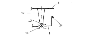
図2は、エンジンカバー4と下部ハウジング部品2との間に本発明に従って形成された結合領域の原理的構造を示す模式拡大側面図である。一体的なプラスチック射出成形品として形成されたエンジンカバー4は一体成形された縦長支持要素、即ち支持棒10を備えており、この支持棒はエンジンルーム内に当初の組立状態で装着された正規姿勢では下部ハウジング部品2へ向かって突出している。支持棒10はエンジンカバー側の基端部がエンジンカバー4と一体に結合されており、基端部から遠い方の先端部側自由端12の近傍に窄み形状部14を有している。この窄み形状部14の近傍から基端部側へ向かって円錐形に横断面輪郭が拡径されており、この円錐部は主作用横断面16で成端している。
FIG. 2 is a schematic enlarged side view showing the principle structure of the coupling region formed according to the invention between the
エンジンの上面位置に取り付けられた下部ハウジング部品2の結合領域には中央貫通孔を有する弾性リング18からなる弾性固定要素がスナップ嵌めされており、この貫通孔の内径は支持棒10の主作用横断面16の外径よりも小さい。
An elastic fixing element composed of an
下部ハウジング部品内にエアフィルタエレメント6を嵌め込んた後、当初の組立状態でエンジンカバー4を正規姿勢に載置すると、支持棒10の自由端が弾性リング18の貫通孔内に進入し、弾性リングの貫通孔内面に内向きに突出して一体成形された全周ラッチリップ22が窄み形状部14内に係合するまで支持棒10が押し込まれる。この状態でエンジンカバー4は当初の組立状態におけるラッチ機能の作用下にあり、同時に下部ハウジング部品2とエンジンカバー4との間で全周縁部に配置される図示しない弾性シール部材による予荷重の作用下に下部ハウジング部品2にラッチ係合されている。
After the
衝突事故時には、エンジンフード8に外部から作用する衝撃力によってエンジンフード8のみならずエンジンカバー4も支持棒10の長手軸方向で弾性リング18の貫通孔内へ更に押し込まれ、これによって歩行者保護のためのクラッシュ機能が果たされる。この場合、主作用横断面16の幾何学的形状寸法と弾性リング18並びにラッチリップ22の材料特性とによって予め定められた復帰方向の力が衝撃力に対抗するが、この復帰方向の抵抗力を乗り越えて、エンジンカバー4が下部ハウジング部品2へ向かって相対移動できるように構成されている。
At the time of a collision accident, not only the engine hood 8 but also the
図3は、歩行者保護機能を達成するにエンジンカバー4と下部ハウジング部品2との間の結合領域を別の形態に構成した場合の模式拡大側面図である。この変形実施形態では、図2の実施形態とは異なって、当初の組立状態へのラッチ機能と衝突時のクラッシュ機能が互いに分離され、従って支持棒10と弾性固定要素とを対構成とすることによって両方の機能が実現されているのではない。この変形実施形態では、下部ハウジング部品2とエンジンカバー4との間に両者の周縁に沿って形成されたラッチエッジ24の衝合によって当初の組立状態へのラッチ機能が実現されている。このラッチ係合状態において、エンジンカバー6に一体成形された支持棒10の先端部は、下部ハウジング部品2に装着された弾性リング18の貫通孔内に嵌挿されると共に弾性リングの貫通孔内面に内向きに突出して一体成形された全周ラッチリップに予荷重を伴って載置されている。上述のように衝撃力が作用すると、支持棒10が長手軸方向に沿って弾性リング18の貫通孔内へ更に押し込まれ、それによって弾性リング18が押し広げられ、支持棒10は中央貫通孔内へ更に押し込まれて衝撃力を乗り越えることになる。
FIG. 3 is a schematic enlarged side view when the coupling region between the
図4と図5は本発明における機能部材である「弾性固定要素」及び「縦長支持要素」の種々の種々の実施形態を示す拡大縦断面図である。いずれの場合にも支持棒10はエンジンカバー4に一体成形されている。
4 and 5 are enlarged longitudinal sectional views showing various various embodiments of the “elastic fixing element” and the “longitudinal support element” which are functional members in the present invention. In either case, the
図4に示す実施形態では、支持棒10は全周面が閉鎖壁で構成された筒状中空体で形成されており、先端側の自由端12の近傍に窄み形状部14が設けられている。窄み形状部14の内面には、横断面補強の目的で横梁ストラット26が成形されている。図4の実施形態では、弾性リング18は下部ハウジング部品2の取付孔に射出成形されている。
In the embodiment shown in FIG. 4, the
図5に示す別の実施形態では、支持棒10の周壁が片側で開口されている。それ以外の点では図4の支持棒と同様の幾何学的形態である。また、図5の実施形態では弾性リング18が下部ハウジング部品2の固取付孔に装着された別部品からなっている。即ち、弾性リング18は外周面に全周係合溝を有し、この係合溝内に下部ハウジング部品の取付孔の鉤状断面形状の口縁が係合する。この倍、弾性リング18は予め圧縮状態で下部ハウジング部品2の取付孔内に装着されるように幾何学的形状が選ばれている。
In another embodiment shown in FIG. 5, the peripheral wall of the
図6は更に別の実施形態による弾性リング18の縦断面形状を示しており、この弾性リングは図5に示した実施形態と同様の様式で下部ハウジング部品2の取付孔に装着されているが、弾性リングの貫通孔下端側が該リングに一体形成されたカバーフード28によって覆われている点で相違する。このカバーフードは、衝突事故に際して発揮されるべきクラッシュ機能に付加的な弾性力を付与している。
FIG. 6 shows the longitudinal section of an
図7に更に別の実施形態によるエンジンカバーの原理的構造を縦断面図で示すが、この実施形態ではエンジンカバーにエアフィルタハウジングが一体化されている。図7には、本発明に係る構造の枢要部である縦長支持要素は現れていない。エンジンの上面位置に配置されているエンジンカバーは鍋状の下部ハウジングシェル部品30とハウジングカバーの形態の上部ハウジングシェル部品32とからなり、この上部ハウジングシェル部品には図7には現れていないが本発明に係る縦長支持要素が一体形成され、この支持要素を介して上部ハウジングシェル部品が下部ハウジングシェル部品とラッチ係合している。下部ハウジングシェル部品30と上部ハウジングシェル部品32は内部に密閉空間を形成し、この密閉空間が閉鎖された供給空気容積室34を形成する。更にこの供給空気容積室内によく知られているエアフィルタエレメント36が装着されている。
FIG. 7 is a longitudinal sectional view showing the principle structure of an engine cover according to still another embodiment. In this embodiment, an air filter housing is integrated with the engine cover. FIG. 7 does not show the longitudinal support element which is the pivotal part of the structure according to the present invention. The engine cover arranged at the upper surface position of the engine comprises a pan-like lower
本発明の主題は、個々の請求項の主題だけでなく、個々の請求項の組み合せ概念からも想起される。要約書を含めて本願明細書に開示された全ての特徴、特に図示の中空構造体の特徴は、それらが個々に或いは組み合せとして先行技術に対して新規である限りにおいて本発明の技術的範疇に属するものである。 The subject matter of the present invention is recalled not only from the subject matter of the individual claims but also from the combined concept of the individual claims. All the features disclosed herein, including the abstract, especially the features of the illustrated hollow structure, are within the technical scope of the present invention as long as they are new to the prior art individually or in combination. It belongs to.
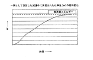
本発明によって達成可能な特定の減速効果を明らかにするために、図8及び図9に一例として設定した減速条件下における代表的な衝撃力対変形ストローク長特性と減速中に消費された仕事量の経時変化を示す。これらの特性曲線は、本発明に従って構成された2つのハウジング部材を相対的に接近移動させたときに得られたものである。 In order to clarify the specific deceleration effect that can be achieved by the present invention, typical impact force versus deformation stroke length characteristics and the amount of work consumed during deceleration under the deceleration conditions set as an example in FIGS. The time-dependent change of is shown. These characteristic curves are obtained when the two housing members constructed according to the present invention are moved relatively close to each other.
図8から判るように、衝撃力と同方向の力に対する抵抗力は量ハウジング部材の接近移動に伴って徐々に上昇し、図2に示した構造体における支持棒10と弾性リング18との幾何学的形状寸法の選定によって支持棒の窄み形状部から基端部側に続く円錐部が弾性リングのラッチリップを乗り越えるときに最初の頂点に達し、次いで弾性リング18のラッチリップが窄み形状部14に嵌ってラッチ係合するときに再びほぼ零にまで低下する。このラッチ係合状態においては上部ハウジング部品はその当初の組立状態における正規位置にある。衝突事故が発生して衝撃力が加わると、両ハウジング部品相互の接近移動による変形ストローク長の増加に伴って抵抗力が支持棒10の主作用横断面から基端部側の拡径形状に基づいて2番目の頂点まで連続的に上昇し、この2番目の頂点における力の大きさは最初の頂点における力の概ね3倍程度である。最初の頂点における力の大きさ[N]はラッチ機能を支配し、2番目の頂点における力の大きさ[N]はクラッシュ機能の圧縮変形の遅延効果を支配する。支持棒10と弾性リング18の幾何学的形状寸法と材質選定を個々に設定しておくことにより、実際に適用する車両に応じた所望の衝撃力対変形ストローク長特性を実現することが可能である。
As can be seen from FIG. 8, the resistance force against the force in the same direction as the impact force gradually increases as the quantity housing member approaches and the geometry of the
図9は一例として設定した減速条件下における減速中に消費された仕事量[W]の経時変化を示しており、曲線が示す仕事量の最大値は総消費エネルギーに相当する。 FIG. 9 shows the change over time of the work [W] consumed during deceleration under the deceleration conditions set as an example, and the maximum value of the work shown by the curve corresponds to the total energy consumption.
2:下部ハウジング部品
4:エンジンカバー
6:エアフィルタエレメント
8:エンジンフード
10:支持棒(縦長支持要素)
12:自由端
14:窄み形状部
16:主作用横断面
18:弾性リング
22:ラッチリップ
24:ラッチエッジ
26:横梁ストラット
28:カバーフード
30:下部ハウジングシェル部品
32:上部ハウジングシェル部品
34:供給空気容積室
36:エアフィルタエレメント
2: Lower housing parts 4: Engine cover 6: Air filter element 8: Engine hood 10: Support rod (vertical support element)
12: Free end 14: Constricted shape part 16: Main action cross section 18: Elastic ring 22: Latch lip 24: Latch edge 26: Cross beam strut 28: Cover hood 30: Lower housing shell part 32: Upper housing shell part 34: Supply air volume chamber 36: Air filter element
Claims (15)
第1ハウジング部品とこれに結合可能な第2ハウジング部品とを備え、
第1ハウジング部品には縦長支持要素(10)が設けられ、該縦長支持要素は第1ハウジング部品側の基端部で第1ハウジング部品に結合されていると共に該基端部から軸方向に離れた先端部側に主作用横断面(16)を有する作用端を備えたものにおいて、
第2ハウジング部品には貫通孔を有する弾性固定要素が配置され、該貫通孔の内径が主作用横断面(16)の外径よりも小さく、且つ、歩行者への強衝撃を回避するために予め定められた変形ストローク長に亘って第1と第2のハウジング部品同士の接近移動に予め定められた減速を与える構成を有し、
縦長支持要素(10)が先端部側の自由端(12)の近傍に補助作用横断面を形成する窄み形状部(14)を有し、該窄み形状部(14)から基端部側へ向かって円錐形に横断面輪郭が拡径されており、
弾性固定要素が第2ハウジングに設けられた結合用取付孔を有する結合領域に配置されていると共に前記結合用取付孔に装着された貫通孔付き弾性リング(18)を含んでおり、
弾性リングは、中央貫通孔の内周面が内方へ突出するラッチリップであり、このラッチリップの突出先端部は前記窄み形状部(14)の外周面形状に対応する幾何学的形状とされたことを特徴とするハウジング。A housing that can be mounted on a car,
A first housing part and a second housing part connectable to the first housing part;
The first housing part is provided with a longitudinal support element (10), which is connected to the first housing part at the base end on the side of the first housing part and is axially spaced from the base end. In what is provided with a working end having a main working cross section (16) on the distal end side,
An elastic fixing element having a through hole is arranged in the second housing part, the inner diameter of the through hole is smaller than the outer diameter of the main action cross section (16), and in order to avoid a strong impact on the pedestrian have a structure that gives advance first over a deformation stroke length defined as a predetermined deceleration to approach movement of the second housing part between,
The vertically long support element (10) has a constricted shape portion (14) forming an auxiliary action cross section in the vicinity of the free end (12) on the distal end side, and the proximal end portion side from the constricted shape portion (14) The cross-sectional contour is expanded in a conical shape toward the
The elastic fixing element is disposed in a coupling region having a coupling mounting hole provided in the second housing and includes an elastic ring (18) with a through hole mounted in the coupling mounting hole;
The elastic ring is a latch lip in which the inner peripheral surface of the central through hole protrudes inward, and the protruding tip of the latch lip has a geometric shape corresponding to the outer peripheral surface shape of the narrowed portion (14). A housing characterized by being made .
Applications Claiming Priority (5)
| Application Number | Priority Date | Filing Date | Title |
|---|---|---|---|
| DE200610023350 DE102006023350B4 (en) | 2006-05-17 | 2006-05-17 | On a motor vehicle attachable housing with integrated pedestrian protection function |
| DE102006023350.6 | 2006-05-17 | ||
| DE202006016033.7 | 2006-10-16 | ||
| DE200620016033 DE202006016033U1 (en) | 2006-05-17 | 2006-10-16 | System protecting pedestrian in case of collision with vehicle, comprises vertical extension located at engine cover |
| PCT/DE2007/000891 WO2007131497A1 (en) | 2006-05-17 | 2007-05-16 | Housing that can be fixed to a motor vehicle and has an integrated pedestrian protection function |
Publications (3)
| Publication Number | Publication Date |
|---|---|
| JP2009537721A JP2009537721A (en) | 2009-10-29 |
| JP2009537721A5 JP2009537721A5 (en) | 2010-07-08 |
| JP4997422B2 true JP4997422B2 (en) | 2012-08-08 |
Family
ID=37681554
Family Applications (1)
| Application Number | Title | Priority Date | Filing Date |
|---|---|---|---|
| JP2009510277A Expired - Fee Related JP4997422B2 (en) | 2006-05-17 | 2007-05-16 | Housing with pedestrian protection that can be fixed to a car |
Country Status (5)
| Country | Link |
|---|---|
| US (1) | US7998232B2 (en) |
| EP (1) | EP2018301B1 (en) |
| JP (1) | JP4997422B2 (en) |
| DE (2) | DE202006016033U1 (en) |
| WO (1) | WO2007131497A1 (en) |
Families Citing this family (21)
| Publication number | Priority date | Publication date | Assignee | Title |
|---|---|---|---|---|
| FR2913253B1 (en) * | 2007-03-01 | 2009-05-08 | Peugeot Citroen Automobiles Sa | AIR FILTER HAVING PIVOTANTS. |
| JP5053871B2 (en) * | 2008-01-11 | 2012-10-24 | 株式会社イノアックコーポレーション | Intake duct for vehicle |
| DE102008031399A1 (en) | 2008-07-02 | 2009-03-19 | Daimler Ag | Engine cover for front end of passenger car, has surface region that is moved into evasion position during accidental force impact, where surface region is made of flexible material i.e. flexible plastic material |
| IT1394274B1 (en) | 2009-06-17 | 2012-06-06 | Bmc Srl | FILTERING DEVICE FOR AIR ASPIRATED BY A MOTOR OF A VEHICLE |
| DE202009017786U1 (en) | 2009-09-17 | 2010-06-17 | GM Global Technology Operations, Inc., Detroit | Body for a motor vehicle |
| DE102010005364A1 (en) | 2010-01-22 | 2011-07-28 | GM Global Technology Operations LLC, ( n. d. Ges. d. Staates Delaware ), Mich. | Housing for installation between outer skin on motor vehicle body and rigid substructure, is stiffened by support that is extended between outer housing part and inner housing part of housing |
| US8298308B2 (en) | 2010-03-15 | 2012-10-30 | GM Global Technology Operations LLC | Air filter assembly |
| DE102010014079A1 (en) * | 2010-04-07 | 2011-10-13 | Gm Global Technology Operations Llc (N.D.Ges.D. Staates Delaware) | Fastening device of a cover on a fixed, arranged in the front region component of a motor vehicle |
| DE102010029592A1 (en) * | 2010-06-01 | 2011-12-01 | Ford Global Technologies, Llc | Türverkrallung for a motor vehicle |
| DE102012009045A1 (en) | 2012-05-04 | 2013-11-07 | Carl Freudenberg Kg | Filter element arrangement for engine supply air filtration in suction system of motor car for ensuring pedestrian protection, has filter element partially accommodated in housing, and movable relative to component |
| DE102012212251A1 (en) * | 2012-07-12 | 2014-01-16 | Mahle International Gmbh | Fresh air system component |
| DE102013010848B4 (en) * | 2013-06-28 | 2023-09-28 | Andreas Stihl Ag & Co. Kg | Round filter arrangement with a carburettor |
| DE102013222593A1 (en) * | 2013-11-07 | 2015-05-07 | Montaplast Gmbh | plug-in coupling |
| WO2015077245A1 (en) * | 2013-11-19 | 2015-05-28 | Cummins Filtration Ip, Inc. | High frequency silencer for an air induction system |
| FR3015389A1 (en) * | 2013-12-19 | 2015-06-26 | Cera | MOUNTING AN ACOUSTIC PROTECTION SCREEN ON A MOTOR VEHICLE ENGINE |
| FR3015390A1 (en) * | 2013-12-19 | 2015-06-26 | Cera | ARCHITECTURE OF ACOUSTIC PROTECTION BY A SCREEN ARRANGED ON A MOTOR VEHICLE ENGINE |
| DE102014003291A1 (en) | 2014-03-07 | 2014-09-04 | Daimler Ag | Fastening device for fastening engine covering at internal combustion engine of motor vehicle, has holding elements forming detent connection by relative movement of holding element with respect to ball stud in vehicle height direction |
| US9776118B2 (en) | 2014-08-25 | 2017-10-03 | Mann+Hummel Gmbh | Filter element and housing with cooperating filter media support structures |
| DE102015116775A1 (en) * | 2015-10-02 | 2017-04-06 | Kiekert Ag | Safety device for front hoods with electric drive u.rastbarem actuator |
| US10315589B2 (en) | 2017-10-05 | 2019-06-11 | Ford Global Technologies, Llc | Reinforced vehicle component cover |
| US10495024B2 (en) | 2017-10-05 | 2019-12-03 | Ford Global Technologies, Llc | Reinforced vehicle component cover |
Family Cites Families (20)
| Publication number | Priority date | Publication date | Assignee | Title |
|---|---|---|---|---|
| US6161513A (en) | 1999-03-01 | 2000-12-19 | Ford Global Technologies, Inc. | Plenum module having a runner pack insert |
| DE60038938D1 (en) * | 1999-11-30 | 2008-07-03 | Honda Motor Co Ltd | A-pillar for vehicles |
| DE60226138T2 (en) * | 2002-09-20 | 2009-05-28 | Ford Global Technologies, LLC, Dearborn | Safety device for pedestrians |
| DE10257072A1 (en) | 2002-12-06 | 2004-06-24 | Mann + Hummel Gmbh | Component for installation at a short distance under the outer body skin of a motor vehicle in the pedestrian impact area |
| DE10259591A1 (en) * | 2002-12-19 | 2004-07-15 | Daimlerchrysler Ag | Bonnet with pedestrian protection |
| JP4296493B2 (en) * | 2003-02-28 | 2009-07-15 | 東海ゴム工業株式会社 | Cover mounting structure |
| DE10314220C5 (en) * | 2003-03-28 | 2009-09-10 | Woco Industrietechnik Gmbh | Cover for at least one component in an engine compartment of a motor vehicle |
| US7712569B2 (en) * | 2003-06-06 | 2010-05-11 | Magna Electronics Europe Gmbh & Co. Kg | Device and method for raising the hood of a motor vehicle during a collision with a pedestrian |
| JP4285301B2 (en) | 2004-03-31 | 2009-06-24 | 豊田合成株式会社 | Engine cover mounting structure |
| JP4296502B2 (en) * | 2004-10-01 | 2009-07-15 | 豊田合成株式会社 | Engine cover mounting structure |
| FR2876068B1 (en) * | 2004-10-05 | 2006-12-15 | Valeo Vision Sa | ENERGY DAMPING PROJECTOR FOR MOTOR VEHICLE AND METHOD FOR ABSORBING ENERGY FROM PIECE SHOCK |
| DE102004054274A1 (en) * | 2004-11-09 | 2006-05-11 | Mann + Hummel Gmbh | Intake system for the internal combustion engine of a vehicle |
| JP4591306B2 (en) * | 2005-10-19 | 2010-12-01 | 株式会社デンソー | Collision detection system |
| US7845691B2 (en) * | 2006-04-05 | 2010-12-07 | Ford Global Technologies, Llc | Collision safety system for use with a motor vehicle |
| FR2915451B1 (en) * | 2007-04-26 | 2009-10-09 | Vallourec Vitry | PROLONGED WITH PERFECTED SUPPORT. |
| EP2008884A1 (en) * | 2007-06-28 | 2008-12-31 | Ford Global Technologies, LLC | Bonnet for Motor Vehicles |
| DE602007008098D1 (en) * | 2007-09-10 | 2010-09-09 | Ford Global Tech Llc | Pedestrian safety device for a motor vehicle body |
| DE602007005807D1 (en) * | 2007-10-03 | 2010-05-20 | Ford Global Tech Llc | Pedestrian-safe hood locking structure for a motor vehicle |
| KR100946485B1 (en) * | 2008-05-30 | 2010-03-10 | 현대자동차주식회사 | Impact absorbing device of hood panel |
| FR2932748B1 (en) * | 2008-06-18 | 2010-12-10 | Faurecia Bloc Avant | BUMPER ASSEMBLY AND CORRESPONDING MOTOR VEHICLE |
-
2006
- 2006-10-16 DE DE200620016033 patent/DE202006016033U1/en not_active Expired - Lifetime
-
2007
- 2007-05-16 EP EP20070722439 patent/EP2018301B1/en not_active Expired - Fee Related
- 2007-05-16 US US12/301,072 patent/US7998232B2/en not_active Expired - Fee Related
- 2007-05-16 WO PCT/DE2007/000891 patent/WO2007131497A1/en active Application Filing
- 2007-05-16 JP JP2009510277A patent/JP4997422B2/en not_active Expired - Fee Related
- 2007-05-16 DE DE200750001596 patent/DE502007001596D1/en active Active
Also Published As
| Publication number | Publication date |
|---|---|
| WO2007131497A1 (en) | 2007-11-22 |
| JP2009537721A (en) | 2009-10-29 |
| DE202006016033U1 (en) | 2007-01-11 |
| US20090242309A1 (en) | 2009-10-01 |
| EP2018301B1 (en) | 2009-09-23 |
| EP2018301A1 (en) | 2009-01-28 |
| US7998232B2 (en) | 2011-08-16 |
| DE502007001596D1 (en) | 2009-11-05 |
Similar Documents
| Publication | Publication Date | Title |
|---|---|---|
| JP4997422B2 (en) | Housing with pedestrian protection that can be fixed to a car | |
| JP2009537721A5 (en) | ||
| CA1111875A (en) | Energy-absorbing bumper assembly | |
| US5577784A (en) | Vehicle bumper | |
| KR101184281B1 (en) | Roll-rod for vehicle | |
| US6874831B1 (en) | Front structure for a motor vehicle | |
| KR100487993B1 (en) | Automobile plastic seat back frame panel by injection molding process | |
| KR20100104457A (en) | Crash box type bumper | |
| CA2454343C (en) | Composite component integration panel | |
| KR20120061072A (en) | Bumper back-beam for vehicle | |
| KR102009795B1 (en) | Front bumper integrated stiffner | |
| JP2011020614A (en) | Hood panel for automobile | |
| KR102009809B1 (en) | Rear bumper integrated back beam | |
| KR20180107484A (en) | fixing bracket for rear bumper | |
| KR20170018157A (en) | Beam for bumper | |
| JP5572122B2 (en) | Car cabin side wall structure | |
| KR102294003B1 (en) | bumper of vehicles | |
| JP5096785B2 (en) | Sound absorbing structure | |
| KR102545355B1 (en) | door trim for vehicle | |
| KR20210062215A (en) | Lower stiffener unit for automobile | |
| JP4664879B2 (en) | Vehicle intake duct | |
| KR102294000B1 (en) | bumper of vehicles | |
| KR101550416B1 (en) | Hybrid bumper | |
| CN212984969U (en) | Automobile trunk shock-absorbing dustproof sleeve assembly | |
| KR20100055224A (en) | Bumper of car |
Legal Events
| Date | Code | Title | Description |
|---|---|---|---|
| A59 | Written plea |
Free format text: JAPANESE INTERMEDIATE CODE: A59 Effective date: 20090408 |
|
| A521 | Request for written amendment filed |
Free format text: JAPANESE INTERMEDIATE CODE: A821 Effective date: 20081119 |
|
| A521 | Request for written amendment filed |
Free format text: JAPANESE INTERMEDIATE CODE: A523 Effective date: 20090430 |
|
| A521 | Request for written amendment filed |
Free format text: JAPANESE INTERMEDIATE CODE: A523 Effective date: 20100511 |
|
| A621 | Written request for application examination |
Free format text: JAPANESE INTERMEDIATE CODE: A621 Effective date: 20100511 |
|
| A977 | Report on retrieval |
Free format text: JAPANESE INTERMEDIATE CODE: A971007 Effective date: 20110815 |
|
| A131 | Notification of reasons for refusal |
Free format text: JAPANESE INTERMEDIATE CODE: A131 Effective date: 20110817 |
|
| A601 | Written request for extension of time |
Free format text: JAPANESE INTERMEDIATE CODE: A601 Effective date: 20111115 |
|
| A602 | Written permission of extension of time |
Free format text: JAPANESE INTERMEDIATE CODE: A602 Effective date: 20111128 |
|
| A601 | Written request for extension of time |
Free format text: JAPANESE INTERMEDIATE CODE: A601 Effective date: 20111215 |
|
| A602 | Written permission of extension of time |
Free format text: JAPANESE INTERMEDIATE CODE: A602 Effective date: 20111226 |
|
| A521 | Request for written amendment filed |
Free format text: JAPANESE INTERMEDIATE CODE: A523 Effective date: 20120112 |
|
| TRDD | Decision of grant or rejection written | ||
| A01 | Written decision to grant a patent or to grant a registration (utility model) |
Free format text: JAPANESE INTERMEDIATE CODE: A01 Effective date: 20120321 |
|
| A01 | Written decision to grant a patent or to grant a registration (utility model) |
Free format text: JAPANESE INTERMEDIATE CODE: A01 |
|
| A61 | First payment of annual fees (during grant procedure) |
Free format text: JAPANESE INTERMEDIATE CODE: A61 Effective date: 20120409 |
|
| R150 | Certificate of patent or registration of utility model |
Ref document number: 4997422 Country of ref document: JP Free format text: JAPANESE INTERMEDIATE CODE: R150 Free format text: JAPANESE INTERMEDIATE CODE: R150 |
|
| FPAY | Renewal fee payment (event date is renewal date of database) |
Free format text: PAYMENT UNTIL: 20150525 Year of fee payment: 3 |
|
| R250 | Receipt of annual fees |
Free format text: JAPANESE INTERMEDIATE CODE: R250 |
|
| R250 | Receipt of annual fees |
Free format text: JAPANESE INTERMEDIATE CODE: R250 |
|
| R250 | Receipt of annual fees |
Free format text: JAPANESE INTERMEDIATE CODE: R250 |
|
| R250 | Receipt of annual fees |
Free format text: JAPANESE INTERMEDIATE CODE: R250 |
|
| R250 | Receipt of annual fees |
Free format text: JAPANESE INTERMEDIATE CODE: R250 |
|
| R250 | Receipt of annual fees |
Free format text: JAPANESE INTERMEDIATE CODE: R250 |
|
| LAPS | Cancellation because of no payment of annual fees |