JP4990889B2 - Transfer of kinetic energy to and from fluids - Google Patents
Transfer of kinetic energy to and from fluids Download PDFInfo
- Publication number
- JP4990889B2 JP4990889B2 JP2008514819A JP2008514819A JP4990889B2 JP 4990889 B2 JP4990889 B2 JP 4990889B2 JP 2008514819 A JP2008514819 A JP 2008514819A JP 2008514819 A JP2008514819 A JP 2008514819A JP 4990889 B2 JP4990889 B2 JP 4990889B2
- Authority
- JP
- Japan
- Prior art keywords
- blade
- wing
- wings
- fluid
- flutter
- Prior art date
- Legal status (The legal status is an assumption and is not a legal conclusion. Google has not performed a legal analysis and makes no representation as to the accuracy of the status listed.)
- Expired - Fee Related
Links
- 239000012530 fluid Substances 0.000 title claims description 70
- 238000012546 transfer Methods 0.000 title claims description 3
- 230000033001 locomotion Effects 0.000 claims description 50
- 239000000725 suspension Substances 0.000 claims description 28
- 238000000034 method Methods 0.000 claims description 17
- 238000013519 translation Methods 0.000 claims description 15
- 230000002441 reversible effect Effects 0.000 claims description 8
- 230000002457 bidirectional effect Effects 0.000 claims description 3
- 230000000737 periodic effect Effects 0.000 claims description 3
- 238000012986 modification Methods 0.000 claims description 2
- 230000004048 modification Effects 0.000 claims description 2
- XLYOFNOQVPJJNP-UHFFFAOYSA-N water Substances O XLYOFNOQVPJJNP-UHFFFAOYSA-N 0.000 description 14
- 238000013461 design Methods 0.000 description 10
- 230000007246 mechanism Effects 0.000 description 7
- 230000001360 synchronised effect Effects 0.000 description 6
- 238000010586 diagram Methods 0.000 description 5
- 230000006872 improvement Effects 0.000 description 5
- 230000005540 biological transmission Effects 0.000 description 4
- 230000008859 change Effects 0.000 description 4
- 238000006243 chemical reaction Methods 0.000 description 4
- 238000012423 maintenance Methods 0.000 description 4
- 238000005086 pumping Methods 0.000 description 4
- 230000000977 initiatory effect Effects 0.000 description 3
- 238000010248 power generation Methods 0.000 description 3
- 238000013016 damping Methods 0.000 description 2
- 230000000149 penetrating effect Effects 0.000 description 2
- 238000004088 simulation Methods 0.000 description 2
- PEDCQBHIVMGVHV-UHFFFAOYSA-N Glycerine Chemical compound OCC(O)CO PEDCQBHIVMGVHV-UHFFFAOYSA-N 0.000 description 1
- 238000010521 absorption reaction Methods 0.000 description 1
- 230000000712 assembly Effects 0.000 description 1
- 238000000429 assembly Methods 0.000 description 1
- 230000004888 barrier function Effects 0.000 description 1
- 230000008901 benefit Effects 0.000 description 1
- 230000033228 biological regulation Effects 0.000 description 1
- 230000006835 compression Effects 0.000 description 1
- 238000007906 compression Methods 0.000 description 1
- 238000010276 construction Methods 0.000 description 1
- 238000000354 decomposition reaction Methods 0.000 description 1
- 230000001066 destructive effect Effects 0.000 description 1
- 238000011161 development Methods 0.000 description 1
- 238000006073 displacement reaction Methods 0.000 description 1
- 230000009977 dual effect Effects 0.000 description 1
- 230000005611 electricity Effects 0.000 description 1
- 239000000284 extract Substances 0.000 description 1
- 238000005562 fading Methods 0.000 description 1
- ZZUFCTLCJUWOSV-UHFFFAOYSA-N furosemide Chemical compound C1=C(Cl)C(S(=O)(=O)N)=CC(C(O)=O)=C1NCC1=CC=CO1 ZZUFCTLCJUWOSV-UHFFFAOYSA-N 0.000 description 1
- 230000005484 gravity Effects 0.000 description 1
- 238000010438 heat treatment Methods 0.000 description 1
- 238000011835 investigation Methods 0.000 description 1
- 239000007788 liquid Substances 0.000 description 1
- 239000000463 material Substances 0.000 description 1
- 238000005457 optimization Methods 0.000 description 1
- 230000002093 peripheral effect Effects 0.000 description 1
- 238000005381 potential energy Methods 0.000 description 1
- 230000000750 progressive effect Effects 0.000 description 1
- 230000005855 radiation Effects 0.000 description 1
- 230000004044 response Effects 0.000 description 1
- 238000007789 sealing Methods 0.000 description 1
- 239000007787 solid Substances 0.000 description 1
- 230000001629 suppression Effects 0.000 description 1
- 230000009182 swimming Effects 0.000 description 1
Images


Classifications
-
- F—MECHANICAL ENGINEERING; LIGHTING; HEATING; WEAPONS; BLASTING
- F03—MACHINES OR ENGINES FOR LIQUIDS; WIND, SPRING, OR WEIGHT MOTORS; PRODUCING MECHANICAL POWER OR A REACTIVE PROPULSIVE THRUST, NOT OTHERWISE PROVIDED FOR
- F03B—MACHINES OR ENGINES FOR LIQUIDS
- F03B17/00—Other machines or engines
- F03B17/06—Other machines or engines using liquid flow with predominantly kinetic energy conversion, e.g. of swinging-flap type, "run-of-river", "ultra-low head"
- F03B17/062—Other machines or engines using liquid flow with predominantly kinetic energy conversion, e.g. of swinging-flap type, "run-of-river", "ultra-low head" with rotation axis substantially at right angle to flow direction
-
- F—MECHANICAL ENGINEERING; LIGHTING; HEATING; WEAPONS; BLASTING
- F03—MACHINES OR ENGINES FOR LIQUIDS; WIND, SPRING, OR WEIGHT MOTORS; PRODUCING MECHANICAL POWER OR A REACTIVE PROPULSIVE THRUST, NOT OTHERWISE PROVIDED FOR
- F03D—WIND MOTORS
- F03D5/00—Other wind motors
- F03D5/06—Other wind motors the wind-engaging parts swinging to-and-fro and not rotating
-
- F—MECHANICAL ENGINEERING; LIGHTING; HEATING; WEAPONS; BLASTING
- F03—MACHINES OR ENGINES FOR LIQUIDS; WIND, SPRING, OR WEIGHT MOTORS; PRODUCING MECHANICAL POWER OR A REACTIVE PROPULSIVE THRUST, NOT OTHERWISE PROVIDED FOR
- F03D—WIND MOTORS
- F03D5/00—Other wind motors
-
- F—MECHANICAL ENGINEERING; LIGHTING; HEATING; WEAPONS; BLASTING
- F05—INDEXING SCHEMES RELATING TO ENGINES OR PUMPS IN VARIOUS SUBCLASSES OF CLASSES F01-F04
- F05B—INDEXING SCHEME RELATING TO WIND, SPRING, WEIGHT, INERTIA OR LIKE MOTORS, TO MACHINES OR ENGINES FOR LIQUIDS COVERED BY SUBCLASSES F03B, F03D AND F03G
- F05B2210/00—Working fluid
- F05B2210/16—Air or water being indistinctly used as working fluid, i.e. the machine can work equally with air or water without any modification
-
- F—MECHANICAL ENGINEERING; LIGHTING; HEATING; WEAPONS; BLASTING
- F05—INDEXING SCHEMES RELATING TO ENGINES OR PUMPS IN VARIOUS SUBCLASSES OF CLASSES F01-F04
- F05B—INDEXING SCHEME RELATING TO WIND, SPRING, WEIGHT, INERTIA OR LIKE MOTORS, TO MACHINES OR ENGINES FOR LIQUIDS COVERED BY SUBCLASSES F03B, F03D AND F03G
- F05B2240/00—Components
- F05B2240/40—Use of a multiplicity of similar components
-
- F—MECHANICAL ENGINEERING; LIGHTING; HEATING; WEAPONS; BLASTING
- F05—INDEXING SCHEMES RELATING TO ENGINES OR PUMPS IN VARIOUS SUBCLASSES OF CLASSES F01-F04
- F05B—INDEXING SCHEME RELATING TO WIND, SPRING, WEIGHT, INERTIA OR LIKE MOTORS, TO MACHINES OR ENGINES FOR LIQUIDS COVERED BY SUBCLASSES F03B, F03D AND F03G
- F05B2250/00—Geometry
- F05B2250/40—Movement of component
- F05B2250/42—Movement of component with two degrees of freedom
-
- Y—GENERAL TAGGING OF NEW TECHNOLOGICAL DEVELOPMENTS; GENERAL TAGGING OF CROSS-SECTIONAL TECHNOLOGIES SPANNING OVER SEVERAL SECTIONS OF THE IPC; TECHNICAL SUBJECTS COVERED BY FORMER USPC CROSS-REFERENCE ART COLLECTIONS [XRACs] AND DIGESTS
- Y02—TECHNOLOGIES OR APPLICATIONS FOR MITIGATION OR ADAPTATION AGAINST CLIMATE CHANGE
- Y02E—REDUCTION OF GREENHOUSE GAS [GHG] EMISSIONS, RELATED TO ENERGY GENERATION, TRANSMISSION OR DISTRIBUTION
- Y02E10/00—Energy generation through renewable energy sources
- Y02E10/20—Hydro energy
-
- Y—GENERAL TAGGING OF NEW TECHNOLOGICAL DEVELOPMENTS; GENERAL TAGGING OF CROSS-SECTIONAL TECHNOLOGIES SPANNING OVER SEVERAL SECTIONS OF THE IPC; TECHNICAL SUBJECTS COVERED BY FORMER USPC CROSS-REFERENCE ART COLLECTIONS [XRACs] AND DIGESTS
- Y02—TECHNOLOGIES OR APPLICATIONS FOR MITIGATION OR ADAPTATION AGAINST CLIMATE CHANGE
- Y02E—REDUCTION OF GREENHOUSE GAS [GHG] EMISSIONS, RELATED TO ENERGY GENERATION, TRANSMISSION OR DISTRIBUTION
- Y02E10/00—Energy generation through renewable energy sources
- Y02E10/30—Energy from the sea, e.g. using wave energy or salinity gradient
-
- Y—GENERAL TAGGING OF NEW TECHNOLOGICAL DEVELOPMENTS; GENERAL TAGGING OF CROSS-SECTIONAL TECHNOLOGIES SPANNING OVER SEVERAL SECTIONS OF THE IPC; TECHNICAL SUBJECTS COVERED BY FORMER USPC CROSS-REFERENCE ART COLLECTIONS [XRACs] AND DIGESTS
- Y02—TECHNOLOGIES OR APPLICATIONS FOR MITIGATION OR ADAPTATION AGAINST CLIMATE CHANGE
- Y02E—REDUCTION OF GREENHOUSE GAS [GHG] EMISSIONS, RELATED TO ENERGY GENERATION, TRANSMISSION OR DISTRIBUTION
- Y02E10/00—Energy generation through renewable energy sources
- Y02E10/70—Wind energy
Description
本出願は、2005年6月1日に出願された米国仮出願第60/685,891号の利益を主張するものである。 This application claims the benefit of US Provisional Application No. 60 / 685,891, filed Jun. 1, 2005.
本発明は、リー・アーノルド博士の米国特許第4,184,805号(1980年1月)、米国特許第4,347,036号(1982年8月)及び米国特許第6,273,680号(2001年8月)に開示された方法と装置の改良に関するものである。 The present invention relates to Dr. Lee Arnold US Pat. No. 4,184,805 (January 1980), US Pat. No. 4,347,036 (August 1982) and US Pat. No. 6,273,680. The present invention relates to an improvement of the method and apparatus disclosed in (August 2001).
本発明は、移動する流体流に含まれる運動エネルギーを用いて有用な動力を作りだす技術及び装置、特に、片持ち支持された懸垂バーのみによって移動する流体内に保持された翼の列に関するものである。逆相で動く翼の列は、2以上の自由度を必要とするフラッタ現象を利用して、発電のために流体からエネルギーを抽出するように配置できる。或いは、翼を外部の動力源によって駆動することにより、外部的にプログラムされた振動(この場合も2以上の自由度を必要とする)を利用して、推進やポンピングを行うために流体にエネルギーを注入する。 The present invention relates to a technique and apparatus for producing useful power using kinetic energy contained in a moving fluid flow, and more particularly to a row of wings held in a fluid moving only by a cantilevered suspension bar. is there. A row of wings moving in reverse phase can be arranged to extract energy from the fluid for power generation, utilizing the flutter phenomenon that requires more than one degree of freedom. Alternatively, by driving the wings with an external power source, the fluid can be energized for propulsion and pumping using externally programmed vibrations (again requiring more than one degree of freedom). Inject.
数世紀前においては人間社会の主要な動力源であった再生可能資源(renewable resource)には、太陽、風力、水力、波及び潮せき力が含まれる。全ての再生可能資源は、潮せき力を除き、太陽エネルギーから得られる。潮せき力は、月の重力によって生じる(地球の核に貯蔵されている熱から得られる地熱は、厳密に言えば再生可能資源ではない)。能動的及び受動的なソーラパワー、風、水、波及び海流のエネルギーは、全て地球の気候周期から生じており、この気候周期は、究極的には全て太陽の放射によって引き起こされる。 Renewable resources, which were the main power sources of human society centuries ago, include the sun, wind, hydropower, waves and tidal power. All renewable resources are derived from solar energy, except for tidal power. Tidal power is generated by the gravity of the moon (geothermal energy from the heat stored in the Earth's core is not strictly a renewable resource). Active and passive solar power, wind, water, waves, and ocean current energy all originate from the Earth's climate cycle, which is ultimately all caused by solar radiation.
再生可能エネルギー源を有用な仕事に変換するための効率的な手段についての調査には、揚力又は抗力を用いて風の運動エネルギーを機械的エネルギーに変換する機械的風力タービン、及び流れる水の運動エネルギー又は高い所に貯蔵された水の位置エネルギーを機械的エネルギーに変換する機械的水力タービンが含まれる。殆どの場合、このようにして変換されたエネルギーは、最終的な分配と使用のために電力に変換される。 Investigations on efficient means for converting renewable energy sources into useful work include mechanical wind turbines that use wind or motive force to convert wind kinetic energy into mechanical energy, and flowing water motion A mechanical hydro turbine is included that converts the potential energy of energy or high stored water to mechanical energy. In most cases, the energy converted in this way is converted to electrical power for final distribution and use.
米国特許第1,486,040号(Schieferstein)は、機械的に駆動される振動ベーンを用いた推進手段を開示しているが、自由度は1でしかない。 U.S. Pat. No. 1,486,040 (Schieferstein) discloses propulsion means using mechanically driven vibrating vanes, but with only one degree of freedom.
米国特許第2,783,022号(Salzer)は、上下運動を通して水平のシャフトを回転させる一連のフロートを含む海洋波力変換装置にいて述べている。この装置は振動翼を採用していない。 U.S. Pat. No. 2,783,022 (Salzer) describes an ocean wave force transducer that includes a series of floats that rotate a horizontal shaft through up and down motion. This device does not employ vibrating blades.
米国特許第3,040,976号(de Mattos)は、機械的に駆動される振動ベーンの平行な群を使用した空気推進手段を開示しているが、この場合も自由度は1でしかない。 U.S. Pat. No. 3,040,976 (de Mattos) discloses an air propulsion means using parallel groups of mechanically driven vibrating vanes, again with only one degree of freedom. .
米国特許第3,508,840号(Lederlin)は、自己発生渦を再循環するために湾曲形状にされた気中翼又は一連のフラッピング気中翼を開示している。その様な気中翼は、フラッタ又は逆相で運転されていない。 U.S. Pat. No. 3,508,840 (Lederlin) discloses an airfoil or series of flapping airfoils that are curved to recirculate self-generated vortices. Such air wings are not operated in flutter or reverse phase.
米国特許第3,783,858号(Ashikian)は、空気柱中の共振振動を用いて液体を加熱する手段を開示している。この発明は、逆相フラッタの翼を用いて流体を機械的エネルギーに変換しない。 U.S. Pat. No. 3,783,858 (Ashikian) discloses means for heating a liquid using resonant vibrations in an air column. The invention does not convert fluid into mechanical energy using anti-phase flutter wings.
米国特許第3,883,750号(Uzell)は、ベンチュリーを内蔵した水平軸回転プロペラ型の風力タービンについて述べている。 U.S. Pat. No. 3,883,750 (Uzell) describes a horizontal axis rotating propeller type wind turbine incorporating a venturi.
米国特許第3,995,972号(Nassar)は、振動型風力変換機を開示しており、これにおいては、1個又は数個の気中翼が、各行程の終わりにおいて気中翼のピッチ角を反転するピッチ変更装置を用いて往復動させられる。この装置は、2以上の自由度でのフラッタを採用しておらず、記載された気中翼のスタックは逆相で動作しない。 U.S. Pat. No. 3,995,972 (Nassar) discloses an oscillating wind power converter in which one or several aerofoils are used at the end of each stroke. It is reciprocated using a pitch changing device that reverses the angle. This device does not employ flutter with more than two degrees of freedom and the described airfoil stack does not operate in reverse phase.
米国特許第4,024,409号(Payne)は、ワイヤ、長い円筒、又は気中翼の共振反力を利用した振動流体力変換装置を開示している。ワイヤ、長い円筒、又は気中翼は、到来する風に晒され、一方の表面で渦が発生され、その表面に力が加えられ、この表面が静止位置から移動し、反対側の表面に新しい渦を作る。この新しい渦により、本体に半体方向の力が加えられ、共振振動が生じる。この共振振動からエネルギーを減衰力として取り出すことができる。この発明の気中翼の実施形態では、気中翼が、渦の発散(shedding)に反応して、フラッタではなく、自由度1で振動する。 U.S. Pat. No. 4,024,409 (Payne) discloses an oscillating fluid force transducer utilizing the resonant reaction force of a wire, long cylinder, or airfoil. A wire, long cylinder, or aerial wing is exposed to the incoming wind, creating a vortex on one surface, applying a force to that surface, this surface moving from a rest position, and a new one on the opposite surface Create a vortex. Due to this new vortex, a half-body force is applied to the main body, and resonance vibration occurs. Energy can be extracted as a damping force from this resonance vibration. In the aerofoil embodiment of the present invention, the aerofoil oscillates with one degree of freedom rather than flutter in response to vortex shedding.
米国特許第4,170,738号(Smith)は、海中の水の運動からエネルギーを抽出し、その運動を往復動するラック・ピニオン手段を介して双方向発電機に伝達する、抗力によって作動される装置(panemone)を開示している。この装置は、翼、フラッタ、又は逆相運動を採用していない。 U.S. Pat. No. 4,170,738 (Smith) is actuated by a drag that extracts energy from the movement of water in the sea and transmits the movement to a bidirectional generator via a rack and pinion means that reciprocates. A device (panemone) is disclosed. This device does not employ wings, flutter, or reverse phase motion.
米国特許第4,184,805号(Arnold)は、空気中又は水中における翼列のフラッタでの逆相運動について記載した最初の基本特許である。本発明は、アーノルド特許についての根本的な改良であり、各翼に取り付けられた機構及び連結の全てが、モジュール式の動力供給及び運動制御システムに結合された単一の片持ち支持式懸垂バーによって置き換えられた。 U.S. Pat. No. 4,184,805 (Arnold) is the first basic patent that describes anti-phase motion of blade cascade flutter in air or water. The present invention is a fundamental improvement over the Arnold patent, where all the mechanisms and connections attached to each wing are combined into a modular power supply and motion control system in a single cantilevered suspension bar. Replaced by
米国特許第4,347,036号(Arnold)は、同じ原出願の分割であり、米国特許第4,184,805号と同じ装置について述べている。 U.S. Pat. No. 4,347,036 (Arnold) is a division of the same original application and describes the same apparatus as U.S. Pat. No. 4,184,805.
米国特許第5,457,346号(Blumberg)は、上記の米国特許第3,883,750号に類似した水平軸プロペラ型の風力タービンについて述べており、このタービンでは、ベンチュリーが到来する風をタービンロータ上に集める。この装置は、翼、フラッタ現象、又は逆相運動の翼列を使用していない。 U.S. Pat. No. 5,457,346 (Blumberg) describes a horizontal axis propeller-type wind turbine similar to U.S. Pat. No. 3,883,750 described above, in which the Venturi wakes the wind. Collect on turbine rotor. This device does not use wings, fluttering or anti-phase motion cascades.
米国特許第6,273,680号(Arnold)は、米国特許第4,184,805 号に最初に開示されたような振動翼列動力システムの元の機械的実施形態を、慣性質量調整に関する追加の材料及び平坦バリヤによる到来流の集中によって開発を継続している。 US Pat. No. 6,273,680 (Arnold) adds an original mechanical embodiment of a vibrating cascade power system, such as that originally disclosed in US Pat. No. 4,184,805, with respect to inertial mass adjustment. Development continues due to the concentration of incoming flow due to the materials and flat barriers.
空力弾性に関する多くの文献は、一般にフラッタを高度に破壊的な力として取り扱っているが、これは、気中翼において生じることが許されると、必然的にその分解につながるものである。上で引用したアーノルドの特許は、流れる流体から有用なエネルギーを抽出するためにフラッタを原則としてどの様に使用できるかを示している。アーノルドの特許に基づくと共にこれを改善する本発明は、従来の特許に記載された多数の振動する機械部品、連結、ベアリング、ロッド、軸及び歯車を除去することで揺動逆相翼列動力変換機の商業的適用を可能にするものである。 Many literature on aeroelasticity generally treats flutter as a highly destructive force, which inevitably leads to its decomposition if allowed to occur in the airfoil. The Arnold patent cited above shows how flutter can be used in principle to extract useful energy from a flowing fluid. The present invention, which is based on and improves upon the Arnold patent, oscillates anti-phase cascade power conversion by eliminating the numerous oscillating mechanical parts, connections, bearings, rods, shafts and gears described in the prior patents. Enabling commercial application of the machine.
フラッタの分析的処置は全ての流体に適用されるが、空気中におけるフラッタは良く知られているものの、水中でのフラッタは広く研究されておらず観察もされていない。アーノルド博士の特許は、水中においてフラッタを開始して維持するための手段を記載した最初のものである。 Although flutter analytical treatment applies to all fluids, flutter in air is well known, but underwater flutter has not been extensively studied and observed. Dr. Arnold's patent is the first to describe means for initiating and maintaining flutter in water.
本発明は、振動翼列動力システム(Oscillating Cascade Power System(OCPS))の耐久性があり高効率な実施形態の設計的特徴を含むと共に、複数の片持ち支持された翼を含む。この翼は振動されると共に、風等の移動流体、又は流れ(stream)小川、川、海流、潮流、又は有向流において移動する水から抽出した運動エネルギーによってフラッタが生じるようにされる。動力発生システムは、複数の翼のフラッタによって駆動される新規なモジュラー型の動力及び制御モジュールを有する。 The present invention includes the design features of the durable and highly efficient embodiment of the Oscillating Cascade Power System (OCPS) and includes multiple cantilevered wings. The wings are vibrated and fluttered by kinetic energy extracted from moving fluids such as wind or water moving in stream streams, rivers, ocean currents, tidal currents, or directed flows. The power generation system has a novel modular power and control module driven by a plurality of wing flutters.
片持ち支持された翼の使用により、米国特許第4,184,805号、第4,347,036号及び第6,273,680号に記載された従来の翼に取り付けられていた非常に多量の物理的機構の必要性を無くすことができる。翼は、作動流体又は電気を使用するプログラム可能な制御サーボシステムによって制御可能である。制御プログラムは、逆相フラッタモードで動作する翼の運動方程式に基づくアルゴリズムを含んでいてもよい。 Due to the use of cantilevered wings, the very large amount attached to the conventional wings described in US Pat. Nos. 4,184,805, 4,347,036 and 6,273,680 The need for physical mechanisms can be eliminated. The wings can be controlled by a programmable control servo system using working fluid or electricity. The control program may include an algorithm based on a wing motion equation operating in the anti-phase flutter mode.
更に、本発明の装置は、移動する流体流から利用可能な多量の運動エネルギーを、多量の機構を取り付けることなく、片持ち支持された翼の平行列を用いることによって効率的に利用する。本明細書で使用する一般的な「翼」という用語は、流水中で使用される「水中翼」、風エネルギー変換に使用される「気中翼」、又は推進に使用される「パドル」の概念を含む。より詳細には航空機のために揚力を発生するために使用される固定又は回転翼(wing)を指す「気中翼」という用語は、本発明の情況では当てはまらない。 Furthermore, the device of the present invention efficiently utilizes the large amount of kinetic energy available from a moving fluid stream by using a cantilevered parallel row of wings without the need for a large amount of mechanism. As used herein, the general term “wing” refers to “hydrofoil” used in flowing water, “airfoil” used for wind energy conversion, or “paddle” used for propulsion. Including concept. More specifically, the term “air wing”, which refers to a fixed or rotating wing used to generate lift for an aircraft, does not apply in the context of the present invention.
本発明の一様相によれば、移動する流体流中において逆相で動作する翼の列に、翼列が動作している間でも,隣接する翼に接触したり影響を与えたりすることなく、個々の翼を列に挿入したり列から取外したりすることができるように、独立したモジュラー型の翼・動力・制御装置が提供される。 According to the uniform phase of the present invention, a row of wings operating in opposite phase in a moving fluid flow without touching or affecting adjacent blades even while the blade row is operating, Independent modular wing, power, and control devices are provided so that individual wings can be inserted into and removed from the row.
フラッタ、即ち2以上の自由度を有する共振振動が翼において起こるためには、翼の有効な慣性質量とストロークエンドでの復元力の存在が重要である。本発明の一様相によれば、システムが動作している間に、慣性質量及び復元力を瞬時に調整して制御し、流れ及び負荷状態が変化している途中でもシステムを連続的に且つ自動的に作動させることを可能にする新規な手段が提供される。 In order for flutter, i.e. resonant vibrations with more than two degrees of freedom, to occur in the wing, the existence of an effective inertial mass of the wing and a restoring force at the stroke end is important. According to one aspect of the present invention, while the system is in operation, the inertial mass and restoring force are adjusted and controlled instantaneously, allowing the system to be continuously and automatically controlled even during changes in flow and load conditions. A novel means is provided that allows the system to be activated automatically.
静止位置では、翼の迎え角は零である。翼を移動している流体流に沈めても振動は生じない。従来技術では、機構を始動しフラッタを開始するために翼を物理的に「揺動」させる必要があった。本発明の一様相によれば、手動による介入を伴うことなく、振動を遠隔的に開始するための手段が提供される。更に、従来技術では、流体の流れを止めるか、過大な負荷を加えて機構を止めることにより振動に打ち勝つ以外の方法で揺動する翼を停止する手段が設けられていなかった。本発明の別の様相によれば、振動する翼の内の1個又は全ての翼の迎え角を零にして1個又は全ての翼を瞬時に停止し、流体が流れ続けている間でも、翼又は関連する機構に対しての過大な応力や損傷を伴うことなく、動力出力を遮断する手段が提供される。 In the rest position, the angle of attack of the wing is zero. No vibration occurs when the wing is submerged in the moving fluid stream. In the prior art, it was necessary to physically “swing” the wing in order to start the mechanism and start the flutter. According to one aspect of the present invention, means are provided for remotely initiating vibrations without manual intervention. Further, in the prior art, there is no means for stopping the wings that swing by a method other than overcoming the vibration by stopping the flow of fluid or stopping the mechanism by applying an excessive load. According to another aspect of the present invention, even if one or all of the oscillating wings have zero angle of attack and one or all of the wings are instantaneously stopped and fluid continues to flow, Means are provided for shutting off the power output without undue stress or damage to the wing or associated mechanism.
本発明の別の様相によれば、複数の個別の翼モジュールが固定される2つの目的を持つ支持構造体が提供され、この構造体は、翼モジュールを中央制御装置に接続するために使用される動力及び制御マニホールドも支持している。マニホールドには一連のマルチチャンネル閉止弁とレセプタクルが設けられており、個々の翼モジュール上のマルチチャンネルコネクタを容易に接続したり取り外したりできる。 In accordance with another aspect of the present invention, a dual purpose support structure is provided to which a plurality of individual wing modules are secured, which structure is used to connect the wing module to a central controller. Power and control manifolds are also supported. The manifold is provided with a series of multi-channel shut-off valves and receptacles that allow easy connection and removal of multi-channel connectors on individual wing modules.
本発明の更なる様相によれば、流体速度及び負荷を含む、内部及び外部システムパラメータの全てを電子的に監視し、これらのデータを特別な制御アルゴリズムによって制御されるプログラム可能なロジック制御装置内において処理することによって、慣性質量と復元力を連続的に調整することが可能となり、これにより、システムの性能を常時最適化できるだけでなく、フラッタが始まる限界流体速度を低下させると共にシステムを安全に運転できる最大即ちシャットダウン速度を上昇させることによってシステムの動作範囲を拡大できる。従来技術では、そのような改良を行うことが出来なかった。何故なら、振動翼列及びその制御システムは、本質的に全体が機械的であり、慣性質量又は復元力を調節するためには最初に停止しなければならないためである。 According to a further aspect of the present invention, all internal and external system parameters, including fluid velocity and load, are electronically monitored and these data are controlled by special control algorithms in a programmable logic controller. In this way, it is possible to continuously adjust the inertial mass and restoring force, which not only constantly optimizes the performance of the system, but also reduces the critical fluid velocity at which flutter begins and makes the system safer. By increasing the maximum operating or shutdown speed, the operating range of the system can be expanded. In the prior art, such an improvement could not be made. This is because the oscillating cascade and its control system are mechanical in nature and must be stopped first to adjust the inertial mass or restoring force.
翼の列の推進又はポンピングモードに関する本発明の一様相によれば、独立して且つ外部から制御可能な翼モジュールにより、種々の異なるプログラムされた順次的又は同時的運動を個々の翼に自由度2で与えて推進又はポンピング動作を最適化できる。例えば、従来技術では不可能である、列に沿った進行的遊泳動作を再現するように翼列をプログラムできる。 According to one aspect of the present invention relating to blade row propulsion or pumping modes, a variety of different programmed sequential or simultaneous movements can be applied to individual blades by independently and externally controllable blade modules. 2 can optimize propulsion or pumping motion. For example, the wing row can be programmed to reproduce a progressive swimming motion along the row, which is not possible with the prior art.
推進に関する本発明の他の様相によれば、単一の翼を単独で推進又はポンピングモードで作動するようにプログラムすることができ、もしその翼が列のメンバーである場合、列の他のメンバーを横断位置に位置決めし、これにより他の流体流を阻止して河川又は洪水の調節を支援できる。 According to another aspect of the invention relating to propulsion, a single wing can be programmed to operate alone in propulsion or pumping mode, and if that wing is a member of a row, the other members of the row Can be positioned in a transverse position, thereby preventing other fluid flow and assisting in river or flood regulation.
本発明の重要な特徴及び、特にリー・アーノルド博士の3件の特許を含む従来技術との需要な差異を概説したが、これは以下の発明の詳細な説明がより良く分かるようにすると共に、当該技術分野への寄与がより良く理解できるようにするためである。添付の特許請求の範囲の主題を形成する本発明の追加の特徴を以下に説明する。当業者であれば、本発明の幾つかの目的を達成する他の手段を設計するための基礎とし本発明を利用できることが分かるであろう。従って、本発明の請求の範囲は、本発明の全体的な範囲から逸脱しないその様な均等な構造や方法も包含するものと見做すことが重要である。 Having outlined the important features of the present invention and the differences in demand from the prior art, including in particular three patents by Dr. Lee Arnold, this will make the following detailed description of the invention better understood, This is so that the contribution to the technical field can be better understood. Additional features of the invention will be described hereinafter that form the subject of the claims appended hereto. Those skilled in the art will appreciate that the present invention can be used as a basis for designing other means of accomplishing some of the objectives of the present invention. It is important, therefore, that the claims herein be regarded as including such equivalent constructions and methods as do not depart from the overall scope of the invention.
図1は、4枚の鉛直方向翼1を示す。各翼は、円形断面の懸垂バー2のみによって懸垂されている。バー2は、静止している複数組の動力/制御モジュール組立体3の底部から突出している。各組のモジュールは独立しているが、同一である。任意の偶数の動力/制御モジュール3が、強固なシステム支持構造体4に取り付けられている。各翼1の重量は、その翼の動力/制御モジュール3に支持されている。動力/制御モジュール3の各組は、動力モジュール3Aと制御モジュール3Bとからなる。懸垂バー2は、動力モジュール3A及び/又は制御モジュール3Bに支持された2個の鉛直方向の同軸ベアリングを貫通しているため、鉛直かつ平行に強固に保持されている。翼1自体は、全体が沈められ、懸垂バー2以外のものには機械的に接続されていない。バー2は、一定範囲内において並進方向(左右方向)には移動自在であると共に、同じく一定範囲内において鉛直方向軸を中心として回転自在であるが、流れ方向(前後方向)の移動及び並進方向の回転(旋回)は制限されている。従って、全ての翼1は、片持ち支持されて常に鉛直状態にしっかり固定されているが、一定の距離だけは回転方向及び並進方向への移動が可能である。特に、翼1は、流体の抵抗力によって下流方向に移動(旋回)することがない。
FIG. 1 shows four vertical wings 1. Each wing is suspended only by a
この構成によって許容される翼の並進運動及び鉛直回転運動の範囲は、任意の姿勢(position)、即ち翼列においてフラッタを開始し持続させるのに必要な翼のピッチと並進の組合せに分解できる。隣接する翼1は、翼列におけるフラッタの必要条件を満たすため、横方向運動及び回転方向運動(ピッチ)の何れにおいても、制御モジュール3Bにより正確な逆相運動に拘束される。各翼1から得られる動力は、対応する動力モジュール3Aにより伝達されるが、この動力モジュールは、翼運動波形の動力行程部分における横方向の翼運動にのみに基づいて動作する。動力/制御モジュール3への接続は、加圧流体による伝達(液圧或いは空気圧)或いは電気的手段により行う。残りの組立体の動作を停止したり、動作に影響を及ぼすことなく、組立体の1個を運転中の発電システムからり取り外して交換できることは、動力/制御モジュール組立体の設計の一特徴である。
The range of wing translation and vertical rotation allowed by this configuration can be broken down into any position, i.e., the combination of wing pitch and translation needed to initiate and sustain flutter in the cascade. Adjacent blades 1 satisfy the flutter requirements in the cascade, and are therefore constrained to precise reverse phase motion by
図2に示すように、制御モジュール3Bは、各翼1に横方向運動(並進)及びそれと独立した回転運動を同時に行わせるための手段である。分析的には、この独立した角運動とz軸運動の組合せは、フラッタを開始し持続させるために必要な翼が行い得るいかなる運動或いはとり得るいかなる姿勢にも分解できる。特に、(a)前縁及び後縁の振動の独立したフェージングと、(b)フラッタを開始し持続させるために必要な前縁及び後縁への差動的復元力及び慣性質量の外部からの印加である。更に、取り付けられた動力モジュール3Aとの組み合わせにより、この機械的設計は、(c)流れ方向且つx軸方向の翼列強度(抗力抑制(drag restraint))及び(d)全ての動作条件における懸垂バー2全ての厳密な平行性を提供する。最後に、各制御/動力モジュール組立体3は、翼列のどの動作軸(並進軸或いは回転軸)とも相互作用することなく翼1を鉛直に支持する。翼懸垂バー2の上端は、動力モジュール及び制御モジュールの両方を貫通し、制御モジュール3B貫通部においては、回転力(トルク)を伝達できるようにスプライン係合されている。鉛直方向の懸垂バー2は、2個のベアリング、即ち、制御モジュール組立体3Bの頂部及び底部に配置されたベアリング(その内の少なくとも1個はスラストベアリングである)によって支持できる。従って、制御モジュール3B自体が静止した状態であっても、各翼懸垂バー2は独立してモジュール内で鉛直方向軸を中心に回転できるが、回転の程度は、回転チャンバ6内の放射状の空間によって制限されている。
As shown in FIG. 2, the control module 3 </ b> B is a means for causing each wing 1 to simultaneously perform a lateral movement (translation) and an independent rotational movement. Analytically, this combination of independent angular and z-axis motion can be broken down into any movement or any possible posture that the wings can perform to initiate and sustain flutter. In particular, (a) independent fading of leading and trailing edge vibrations, and (b) differential restoring force to the leading and trailing edges and external inertial mass required to initiate and sustain flutter. Apply. Furthermore, in combination with the mounted
回転:制御モジュール3Bにおいては、スプラインが形成された翼懸垂バー2は、これに対応してスプラインが形成された回転インペラ5を貫通している。インペラ5は、並進ピストン7B内に配置された回転チャンバ6内において鉛直方向軸を中心に回転できる。インペラ5の回転は、設計により、チャンバ6の放射形状によって約40°に制限されている。インペラ5の中央表面は、小さな間隙によりチャンバ内壁に接触しないように維持されていると共に、内側及び外側の「ピストンリング」タイプのシール8及び9により鉛直方向に密封されている。インペラ5の上端及び下端には同様のシールが設けられ(この中央部断面には図示されていない)、各チャンバセグメントの内部が流体圧に曝されるようになっている。流体導管チャネル10及び11はそれぞれ、並進ピストン7B内において回転チャンバ6から長手方向周囲凹部12及び13まで延びており、更に外部オリフィス14、15に延び、制御モジュール3Bから出る。従って、オリフィス14に加えられた流体圧により、これに対応した回転インペラ5の負の方向(反時計回り)の回転が生じる。同様に、オリフィス15に加えられた流体の圧力により、回転インペラ5の正方向の回転が生じる。並進ピストン7Bの両端に設けられたピストンリング16は、規定された長手方向移動限界内においてピストン7Bが独立した並進運動を行っている間に、オリフィス14、15に加えられた流体圧によってインペラ5がピストン7B内で効率的に回転されることを保証する。即ち、ピストン7Bの位置や運動に関わらず、回転インペラ5は、移動部品やホース、移動接続部なしで、外部から加えられた流体圧によって生じる正確に制御可能なトルク(回転運動)をバー2及び翼1に伝える。
Rotation: In the
並進運動:並進ピストン7Bは、シリンダ17B内を長手方向に移動できる。ピストン7Bは、シリンダ壁とは実際には接触せずに小さな間隙を有して移動するが、前記のピストンリング16により密封されている。ピストンリング16は更に、回転インペラ5に作用する流体も密封する機能を有する。ピストン7Bの両端から、略丸いピストン支持ロッド18Bが突出している。該ロッド18Bは、シリンダ17Bの各端部に取り付けられたリニアベアリング19(通常は、循環ボール式)により支持されている。これらピストン支持ロッド18Bの長さと、該ロッド18Bに対応してシリンダ端部内に形成された孔の深さは、意図されたピストン7Bの並進行程によって決まる。更に、ピストンリングタイプの軸シール20は、同様に移動部品やホース、マニホールドへの移動接続部を用いずに、シリンダ17B内のオリフィス21、22に加えられる流体圧によりピストン7Bが効率的に長手方向の両方向に移動できることを確実にしている。
Translational motion: The
要約すると、上述の手段によって、並進方向及び回転方向における瞬時的位置に関わらず、翼列内の翼1は全て、正確な逆相運動にロックできる。 In summary, by the means described above, all the blades 1 in the cascade can be locked in precise reverse phase motion regardless of the instantaneous position in the translational and rotational directions.
翼の平行性:翼懸垂バー2は制御モジュールピストン7B及び動力モジュールピストン7Aを貫通しているが上部及び下部のベアリングによって回転運動以外は行わないように制限されているため、また、2組の水平方向のピストン支持ロッド18A、18Bがリニアベアリング19B、19A間に延びてz軸方向の角運動(水平方向旋回)が阻止されているため、懸垂バー2に取り付けられた全ての翼1は、常に、また、横方向運動及び回転運動のどの状態においても、平行が保たれていることは明らかである。
Blade parallelism: The
抗力の抑制:同様に、流れ方向の面においては、翼懸垂バー2は、横方向に往復運動するように拘束されている上方ピストン7B及び下方ピストン7Aの両方を貫通しているため、如何なるx軸方向運動(即ち、翼1に作用する流れる水や空気の抵抗による下流方向への旋回であり、その力ベクトルは翼の瞬時ピッチ角によって変化する)が阻止されている。
Drag suppression: Similarly, in the flow direction, the
センタリング力及び補助的な復元力:動力モジュール3A及び制御モジュール3Bには、フラッタを持続するのに必要な周期的な復元力を部分的に或いは全体的に提供すると共に、静止時にピストン7A及び7Bがそれぞれのシリンダ17A及び17Bの中心に位置することを確実にするため、内部バネ18A及び18Bが組み込まれている。バネ18A及び18Bに替えて、空気圧式或いは液圧式のエネルギー吸収/戻し手段を使用できることを理解すべきである。
Centering force and auxiliary restoring force: The
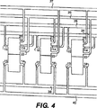
図3は動力モジュール3Aの中央部断面の平面図である。ピストン7Aの並進運動は、制御モジュール3Bのピストン7Bと同一である。いずれの場合においても、二方向に自由なピストン7A及び7Bは、リニアベアリング19A及び19Bにより保持された対応する2個のピストン支持ロッド18A及び18Bによって横方向に運動するように案内されて並進移動する。しかしながら、翼懸垂バー2が、中央の回転インペラ及びシリンダを貫通せずにピストン7Aの中心に設定された密封型単列又は複列ボールベアリング23のみを貫通している点が異なる。従って、翼懸垂バー2は、動力モジュール3A内においては鉛直方向軸を中心として回転自在であるが、懸垂した翼1及びその懸垂バー2が並進すると、ピストン7Aはそれに対応して横方向に運動する。このような横方向のピストン動作に対応して、作動流体は外部オリフィス21及び22を通って出入りする。翼列の全長に亘って延在し図5に示すようにコントローラで終端している6個の共通の流体動力伝達マニホールド24、25、26、27、28、及び29に対して、任意数の独立した水中翼モジュールを接続できる。
FIG. 3 is a plan view of a cross section of the central portion of the
図4は、翼列の幅全体に亘る6個の動力及び制御マニホールドに対する、任意の偶数の動力/制御モジュール3の列の流体接続の概略図である。図4には、連続して隣接する3個の翼モジュールのみが図示されているが、翼の枚数が何枚でもそれらの相互接続を説明するのに十分であろう。各翼モジュールの外部オリフィスは常に完全に静止しているため、マニホールド及び相互接続部は全て、従来の固定型の圧力配管、ジョイント、コネクタを用いて形成されている。各制御モジュールの回転要素の外部オリフィス14、15は、+回転制御マニホールド24及び−回転制御マニホールド25に接続されており、連続して隣接する翼モジュール間において、相互接続された対を形成する制御モジュール同士の方向は交互になっている。即ち、翼A及びCのオリフィス14とモジュールBのオリフィス15はマニホールド24に接続しており、翼列の全ての翼についても同様となっている。これに対応して、モジュールA及びCのオリフィス15とモジュールBのオリフィス14はマニホールド25に接続している。これら2個の回転制御マニホールド24及び25は、図5に示すコントローラ内に見える加圧液圧リザーバにおける終端部において事実上互いに接続されている。結果として、隣接する翼制御モジュールの回転要素が交互に相互接続されていることにより、隣接する翼1の回転運動は全て、正に機械的連結により接続されているかのように互いに正確に逆相状態にロックされる。
FIG. 4 is a schematic diagram of the fluid connections of any even number of power / control module 3 rows for six power and control manifolds across the width of the blade row. Although only three adjacent blade modules are shown in FIG. 4, any number of blades may be sufficient to explain their interconnection. Since the external orifice of each vane module is always completely stationary, all manifolds and interconnects are formed using conventional fixed pressure piping, joints, and connectors. The
これに対応して、全ての翼のオリフィス21及び22は、z軸並進制御マニホールド26、27に交互に接続される。このようにマニホールドを称するのは、翼列に流れ込む流体(空気や水)は+x軸方向に移動すると定義されるが、翼1の横方向運動はz軸に沿って起こるからである。従って、隣接する翼の全ての横方向運動は、上述の回転運動の場合と同様に、互いに正確な逆相状態にロックされる。最後に、上述の回転制御システム及び並進制御システムの作用を組み合わせると、翼列における全ての翼1の運動はいずれも、アーノルド博士のフラッタ解析によって要求されるように、いつでも必ず厳密な逆相状態で起こると共に、翼1の組立体全体が、その他の拘束なしに逆相にロックされた状態で回転方向及び横方向に移動自在である。従って、上述の水中翼の回転方向運動と横方向運動をどのように組み合わせても、適切に制御されれば、アーノルドのフラッタ解析において要求される任意の運動或いは姿勢を再現できる。これは、各アーノルド特許に記載されているように、翼1が、前縁及び後縁の上部及び下部に設けられた機械的連結、相互接続されたレバー及び軸によって拘束されているかのようである。差異は、各翼1は、本発明においては、隣接する翼の端部間には機械的取付部品や接続部品が設けられておらず、他の全ての翼に対して物理的に独立している点である。
Correspondingly, all
図5は、翼列のための流体動力制御中央システムの各要素の概略図である。 FIG. 5 is a schematic diagram of the elements of the fluid power control central system for the cascade.
逆相ロック:システムコントローラは、ここでは、複動ピストンを有する2個の加圧液圧リザーバ28、29として説明する。このピストンの中央位置は翼1の静止位置に対応している(各翼は流れ方向に平行に等間隔で配置されている)。同一の制御機能は、各マニホールドを比例的に流体圧力リザーバ或いは流体戻りリザーバに接続する複数の複式比例バルブの直接的なマイクロプロセッサによるプログラム可能ロジック制御により得られる。各ピストンロッドに設けられた線形位置/速度センサ30は、並進方向及び回転方向の翼の位置及び運動のフィードバック信号をコントローラに送る。より包括的な位置及び運動フィードバックシステムは、各翼モジュールに配置され特定の翼に固有の詳細な誤差情報を提供するセンサを含む。
Reverse phase lock: The system controller is described here as two pressurized
復元力:流体流においてフラッタを持続させるためには、翼変位が最大になる位置の近づいている間及びその位置において有効な復元力を提供する必要があり、正確な復元力は運転サイクル中に変化する。復元力モジュール41は、内部バネ、制御可能に圧縮可能な空気、又はバネ力の電気的シミュレーションの内の一つ又はその組合せを用いて、必要なサイクル端での復元力を提供する。更に、部分的な復元力が、バネ18Cと、ピストン支持ロッド18A及び18Bによる空気の圧縮とによって提供される。
Restoring force: In order to maintain flutter in the fluid flow, it is necessary to provide an effective restoring force while approaching and at the position where the blade displacement is maximized, and the exact restoring force is Change. The restoring force module 41 provides the restoring force at the required cycle end using one or a combination of an internal spring, controllably compressible air, or an electrical simulation of the spring force. Furthermore, a partial restoring force is provided by the
慣性質量:フラッタを持続させるためには、上述の周期的な復元力に加え、翼自体の振動質量に対して正確な量の慣性質量を付加することも必要である。慣性質量モジュール42(図5)は、作動流体接続によって、制御可能な付加質量を翼1に課す。慣性質量付加量の制御は、物理的質量に組み合わされる作動流体(液圧レバー)の比例制御によるか、同一の力の電気的シミュレーションによって行われる。 Inertial mass: In order to maintain the flutter, in addition to the above-mentioned periodic restoring force, it is also necessary to add an accurate amount of inertial mass to the vibrating mass of the blade itself. The inertial mass module 42 (FIG. 5) imposes a controllable additional mass on the wing 1 through the working fluid connection. The inertia mass addition amount is controlled by proportional control of a working fluid (hydraulic lever) combined with a physical mass or by electrical simulation of the same force.
起動:高圧液圧アキュムレータ32(図5)と液圧戻りマニホールドとに接続された多目的電気駆動式可変流量制御弁31により、事前にプログラムされた回転及び並進初期パルスを外部から(流体動力貯蔵部から)翼1へ加え、流れる空気や水の中で振動を開始する。
Start-up: Pre-programmed rotation and translation initial pulses from the outside (fluid power storage unit) by a multi-purpose electrically driven variable
フラッタの制御及び最適化:差動復元力及び補助的な慣性質量を翼1の前縁及び後縁に加えることは、フラッタの開始及び維持の両方に必須である。翼の回転方向及び横方向の位置のフィードバック、周波数、水或いは空気の瞬時流入速度、外部負荷等の情報は、プログラム可能なロジックコントローラへ入力され、該コントローラはプログラムされた運動アルゴリズムに従って、翼1に必要な復元力及び慣性質量の瞬時付加を制御する。 Flutter control and optimization: Applying differential restoring force and auxiliary inertial mass to the leading and trailing edges of wing 1 is essential for both flutter initiation and maintenance. Information such as feedback on the rotational and lateral position of the blade, frequency, instantaneous water or air inflow velocity, external load, etc. is input to a programmable logic controller, which follows the programmed motion algorithm according to the programmed motion algorithm. To control the restoring force and momentary addition of inertial mass required for
フラッタは、一度開始すると、入力される動力(水或いは空気の流れ)、出力負荷(減衰)、差動復元力及び質量の状態が全て適切に維持されていれば、自己持続型の共振現象であることに注目されたい。このような制御調節は、上述の運動状態の継続的な変化を補償するために、連続的及び瞬時的に制御システムによって行われる。 Once started, flutter is a self-sustaining resonance phenomenon if the input power (water or air flow), output load (damping), differential restoring force and mass are all properly maintained. Note that there is. Such control adjustments are made by the control system continuously and instantaneously in order to compensate for the continuous changes in the above-mentioned movement state.
停止:翼静止位置への強制的な戻りを外部からプログラムすることにより、翼列全体或いは単一の翼を非常時に或いはメンテナンスのために即時に停止できる。マニホールドと翼の相互接続部にマルチチャネルバルブを組み込むことにより、翼列全体を停止させずに個別の翼モジュールの接続を切り離して交換できる。 Stop: By programming externally a forced return to the blade rest position, the entire cascade or single blade can be stopped immediately in case of emergency or for maintenance. By incorporating multi-channel valves in the manifold and blade interconnects, individual blade module connections can be disconnected and replaced without stopping the entire blade row.
作動流体圧の維持:補助的な作動流体ループ圧力維持手段を制御システムに組み込まれているが、標準的な水力学設計技法であるため、図示も詳細な説明も行わない。 Maintenance of working fluid pressure: An auxiliary working fluid loop pressure maintenance means is incorporated into the control system, but is not shown or detailed because it is a standard hydraulic design technique.
図6は、配電網が接続された代表的な電力出力手段の概略図であり、翼列から外部負荷へ動力を運ぶ、数ある代替的手段の内の一例を示す。 FIG. 6 is a schematic diagram of a typical power output means connected to a distribution network, showing an example of a number of alternative means for delivering power from the cascade to an external load.
動力リザーバ43からの作動流体は、加圧状態でアキュムレータ32内に貯蔵された後、従来の同期交流発電機34を駆動する流体モータ33に動力を与え、周波数及び位相が同期された電力を配電網に供給する。この図においては、作動流体は、制御されたフラッタが行われている間に動力モジュール3Aによって加圧状態で周期的に押し出され、動力マニホールド39、40を介して送られ、一方向弁を介してリザーバ43に注入される。次に、アキュムレータ32から出て、管理された比例式流れ供給バルブ37を通った後の液圧によって、回転流体モータ33が駆動される。
The working fluid from the
液圧モータ33は、従来の三相ブラシレス同期交流発電機34を直接駆動する。該発電機34は、適切なソリッドステートスイッチギア38と適切な電気保護幹線を介して配電網に接続されている。動力出力開閉装置の閉動作は、シンクロスコープ35により、交流発電機34と配電網とがゼロ電圧点を通過したときに完全に同期された交流発電機34が配電網に接続されるように制御される。同期が行われた後は、流れ供給バルブは、水或いは空気の流れの状態、発電機容量及び温度によって決まる最大動力出力を発生させるために交流発電機の周波数及び出力電流により制御される。
The
図7は、翼モジュール1個の斜視図であり、渦発生を低減するための翼設計の詳細を示す。即ち、(a)図7及び7Aに示すように翼の前縁端部61が丸みが付けられている、(b)翼後縁端部65にフォイルレット(foillet)63が付加されている、(c)図7B及び図7Cに示すように前縁及び後縁に沿って変形可能な可撓性ブーツ67が形成されており、変形の程度は、(中央コントローラにより)瞬時ピッチ角により制御されている。可撓性ブーツ67の長手方向の変形は、翼懸垂バー2を介して供給される流体圧によって発生される。ブーツ67内の適切な形状の2個の空洞部の内の一方に流体圧が供給されると、ブーツの尾部は、中央の静止位置から流れの軸の左又は右に長手方向に捩れる。従って、大きなピッチ角においては、翼1の縁部は、下流に大きな渦流を発生させる(従来技術の)鋭い縁の形状を呈していない。図7B及び図7Cには後縁のブーツ67のみを図示したが、変形可能なブーツは翼1の前縁にも同様に適用できる。
FIG. 7 is a perspective view of one wing module, showing details of the wing design to reduce vortex generation. That is, (a) the leading
翼1の各端部に1個ずつ配置された薄く平坦で滑らかなフォイルレット63及び図示のように適正な形状に整形された角部は、渦の発生を最少にするように作用し、有効な抵抗を抑えると共に効率を高める。フォイルレット63の形状の正確な設計は、翼の幾何形状に特有の空力学的解析に従う。
A thin, flat and
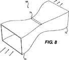
図8は、全体を68で示す完全な振動翼列組立体の斜視図である。該組立体は、全体の動力伝達効率が向上するように流体速度及び流体圧を変更するように設計された流入ダクト70と流出ダクト72とを備える。両ダクトの平面図及び立面図における形状は、流入ダクトと流出ダクトの間の接合部74に配置される翼列の特性及び幾何形状に特有の空力学的解析に応じて、異なるものとすることができる。図9には、接合部74における正味の背圧を低減する手段として、流出ダクト72に挿入されているか或いは流出ダクト72と一体的に形成された横断方向流れ方向変更部材(flow director)76が図示されている。
FIG. 8 is a perspective view of the complete vibrating cascade assembly, indicated generally at 68. The assembly includes an
本発明の全ての特異的ケース或いは用途において、流入又は流出チャネル或いはダクトの設計及び機能が振動翼列及び翼1の設計の一体化された部分を構成する点が本発明の重要な観点である。周囲が囲まれた流体流の両端から等距離に配置された一又は複数の翼が無限の翼列として作用する。図1に示した上述の翼列は、図8に示す完全に周囲が囲まれた筐体内に位置決めされているが、ベッツ限界に従う周囲が囲まれていない環境においてこのような翼列或いは翼を用いることも本発明の範囲に含まれる。 An important aspect of the present invention is that in all specific cases or applications of the present invention, the design and function of the inflow or outflow channel or duct constitute an integrated part of the design of the oscillating cascade and wing 1. . One or more wings arranged equidistantly from both ends of the fluid flow surrounded by them act as an infinite cascade. The above-described cascade shown in FIG. 1 is positioned in the fully enclosed enclosure shown in FIG. 8, but such an cascade or wing is used in an unenclosed environment in accordance with the Betz limit. Use is also within the scope of the present invention.
流体動力伝達手段(液圧)を用いて実施するとして本明細書で説明した中心的概念は、空気圧或いは電気的手段により、或いは流体と電気的手段の組合せにより実施することもできる。 The central concept described herein as being implemented using fluid power transmission means (hydraulic pressure) can also be implemented by pneumatic or electrical means, or a combination of fluid and electrical means.
これら改良の主な目的は、隣接する翼同士を接続するために翼の両端に物理的に取り付けた機構を全てなくすことである。 The main purpose of these improvements is to eliminate all mechanisms physically attached to the ends of the wings to connect adjacent wings.
本発明及びその改良を、好ましい形態を特に参照しつつ説明してきたが、本発明が属する技術分野の当業者が本発明を理解すれば、添付の特許請求の範囲に定義される本発明の範囲から逸脱することなく様々な変形や変更を行えることは明らかであろう。 The present invention and its improvements have been described with particular reference to the preferred embodiments, but only those skilled in the art to which the present invention pertains will understand the present invention and the scope of the invention as defined in the appended claims. It will be apparent that various modifications and changes can be made without departing from the invention.
Claims (14)
Applications Claiming Priority (3)
| Application Number | Priority Date | Filing Date | Title |
|---|---|---|---|
| US68589105P | 2005-06-01 | 2005-06-01 | |
| US60/685,891 | 2005-06-01 | ||
| PCT/US2006/021157 WO2006130719A2 (en) | 2005-06-01 | 2006-06-01 | Transfer of kinetic energy to and from fluids |
Publications (2)
| Publication Number | Publication Date |
|---|---|
| JP2008542621A JP2008542621A (en) | 2008-11-27 |
| JP4990889B2 true JP4990889B2 (en) | 2012-08-01 |
Family
ID=37482289
Family Applications (1)
| Application Number | Title | Priority Date | Filing Date |
|---|---|---|---|
| JP2008514819A Expired - Fee Related JP4990889B2 (en) | 2005-06-01 | 2006-06-01 | Transfer of kinetic energy to and from fluids |
Country Status (12)
| Country | Link |
|---|---|
| US (1) | US8469663B2 (en) |
| EP (1) | EP1888916B1 (en) |
| JP (1) | JP4990889B2 (en) |
| KR (2) | KR101496251B1 (en) |
| CN (1) | CN101223357B (en) |
| AU (1) | AU2006252459B2 (en) |
| BR (1) | BRPI0613517A2 (en) |
| CA (1) | CA2610699C (en) |
| IL (1) | IL187743A0 (en) |
| NZ (1) | NZ564584A (en) |
| RU (1) | RU2362907C1 (en) |
| WO (1) | WO2006130719A2 (en) |
Families Citing this family (14)
| Publication number | Priority date | Publication date | Assignee | Title |
|---|---|---|---|---|
| DE102007003323A1 (en) * | 2007-01-17 | 2008-07-24 | Goran Kaurin | Current generating device, has blades immersed into flowing water, connected by beam arranged parallel to flow direction, and fastened to transmission device to transmit longitudinal movement to rotary axle of generator |
| WO2010027774A1 (en) * | 2008-08-25 | 2010-03-11 | Douglas Joel S | Force fluid flow energy harvester |
| JP5278900B2 (en) * | 2008-10-16 | 2013-09-04 | 学校法人福岡工業大学 | Method and apparatus for converting water energy into electrical power |
| US9478987B2 (en) * | 2009-11-10 | 2016-10-25 | Siemens Aktiengesellschaft | Power oscillation damping employing a full or partial conversion wind turbine |
| RU2454566C2 (en) * | 2010-01-21 | 2012-06-27 | Государственное Образовательное Учреждение Высшего Профессионального Образования "Тамбовский Государственный Технический Университет" | Wind-driven power plant with control device |
| WO2012058761A1 (en) | 2010-11-03 | 2012-05-10 | National Research Council Of Canada | Oscillating foil turbine |
| US8278776B1 (en) | 2011-03-18 | 2012-10-02 | Floyd Arntz | Reciprocating wind-powered transducer employing interleaved airfoil arrays |
| JP5875081B2 (en) * | 2012-11-08 | 2016-03-02 | 学校法人福岡工業大学 | Flutter hydroelectric generator |
| CN104968930B (en) * | 2012-12-12 | 2017-03-29 | 雷普索尔公司 | Energy transducer and energy conversion system |
| BR112015017314A2 (en) | 2013-01-21 | 2017-07-11 | Univ Brown | kinetic energy capture using physical-cyber systems |
| KR101493259B1 (en) | 2013-09-30 | 2015-02-16 | 한국해양과학기술원 | Multiple oscillating tidal stream generators |
| WO2016090057A1 (en) | 2014-12-02 | 2016-06-09 | Reshydro Llc | Modular balanced foil apparatus and method |
| SK288982B6 (en) * | 2015-11-10 | 2022-08-10 | Archee, s.r.o | Apparatus for obtaining mechanical work and/or generating power from fluid flows |
| US10968884B2 (en) * | 2017-09-01 | 2021-04-06 | Douglas Richard English | Fluid flow energy harvester |
Family Cites Families (14)
| Publication number | Priority date | Publication date | Assignee | Title |
|---|---|---|---|---|
| US3040976A (en) * | 1959-08-17 | 1962-06-26 | Mattos Jorge J De | Air propelling means |
| US4024409A (en) * | 1975-01-07 | 1977-05-17 | Payne Peter R | Aeolian windmill |
| US3995972A (en) * | 1975-07-07 | 1976-12-07 | Nassar Esam M | Wind machine with reciprocating blade means |
| US4170738A (en) * | 1977-12-19 | 1979-10-09 | Q Corporation | Energy device powered by the motion of water beneath waves |
| US4347036A (en) * | 1978-03-09 | 1982-08-31 | Lee Arnold | Fluid energy converting method and apparatus |
| US4184805A (en) * | 1978-03-09 | 1980-01-22 | Lee Arnold | Fluid energy converting method and apparatus |
| NL7906627A (en) * | 1979-09-04 | 1981-03-06 | Stichting Energie | DEVICE WITH WITS INCLUDING SUPPLIED WINGS WITH ENLARGED MIXING EFFECT BETWEEN WAKE AND OUTSIDE FLOW. |
| US4255085A (en) * | 1980-06-02 | 1981-03-10 | Evans Frederick C | Flow augmenters for vertical-axis windmills and turbines |
| US5457346A (en) * | 1992-02-10 | 1995-10-10 | Blumberg; Stanley | Windmill accelerator |
| JP3299638B2 (en) * | 1994-09-20 | 2002-07-08 | 株式会社日立製作所 | Turbo fluid machine |
| EP0927304B1 (en) * | 1996-09-20 | 2004-05-12 | Lee Arnold | Extraction of energy from flowing fluids |
| JP2003097408A (en) * | 2001-09-20 | 2003-04-03 | Yamaguchi Technology Licensing Organization Ltd | Energy conversion device utilizing oscillation |
| DE10225025A1 (en) * | 2002-06-06 | 2003-12-24 | Aloys Wobben | Device for handling rotor blades |
| US6877692B2 (en) * | 2003-03-05 | 2005-04-12 | National Research Council Of Canada | Oscillating foil propulsion system |
-
2006
- 2006-06-01 KR KR20137028389A patent/KR101496251B1/en not_active IP Right Cessation
- 2006-06-01 EP EP06771758.7A patent/EP1888916B1/en not_active Not-in-force
- 2006-06-01 AU AU2006252459A patent/AU2006252459B2/en not_active Ceased
- 2006-06-01 RU RU2007148035/06A patent/RU2362907C1/en not_active IP Right Cessation
- 2006-06-01 WO PCT/US2006/021157 patent/WO2006130719A2/en active Application Filing
- 2006-06-01 JP JP2008514819A patent/JP4990889B2/en not_active Expired - Fee Related
- 2006-06-01 CA CA2610699A patent/CA2610699C/en not_active Expired - Fee Related
- 2006-06-01 CN CN2006800248848A patent/CN101223357B/en not_active Expired - Fee Related
- 2006-06-01 KR KR1020077030857A patent/KR20080048991A/en active Application Filing
- 2006-06-01 BR BRPI0613517-0A patent/BRPI0613517A2/en not_active IP Right Cessation
- 2006-06-01 US US11/921,469 patent/US8469663B2/en not_active Expired - Fee Related
- 2006-06-01 NZ NZ564584A patent/NZ564584A/en not_active IP Right Cessation
-
2007
- 2007-11-29 IL IL187743A patent/IL187743A0/en not_active IP Right Cessation
Also Published As
| Publication number | Publication date |
|---|---|
| KR20130125405A (en) | 2013-11-18 |
| EP1888916B1 (en) | 2014-12-31 |
| KR101496251B1 (en) | 2015-02-26 |
| AU2006252459B2 (en) | 2011-04-07 |
| BRPI0613517A2 (en) | 2011-01-18 |
| NZ564584A (en) | 2009-12-24 |
| KR20080048991A (en) | 2008-06-03 |
| US8469663B2 (en) | 2013-06-25 |
| CA2610699A1 (en) | 2006-12-07 |
| CN101223357B (en) | 2010-08-18 |
| CN101223357A (en) | 2008-07-16 |
| RU2362907C1 (en) | 2009-07-27 |
| JP2008542621A (en) | 2008-11-27 |
| EP1888916A4 (en) | 2012-12-26 |
| IL187743A0 (en) | 2008-03-20 |
| WO2006130719A2 (en) | 2006-12-07 |
| WO2006130719A3 (en) | 2007-08-16 |
| US20100143115A1 (en) | 2010-06-10 |
| CA2610699C (en) | 2015-08-11 |
| AU2006252459A1 (en) | 2006-12-07 |
| EP1888916A2 (en) | 2008-02-20 |
Similar Documents
| Publication | Publication Date | Title |
|---|---|---|
| JP4990889B2 (en) | Transfer of kinetic energy to and from fluids | |
| AU727700B2 (en) | Extraction of energy from flowing fluids | |
| US7989973B2 (en) | Fluid-responsive oscillation power generation method and apparatus | |
| US6109863A (en) | Submersible appartus for generating electricity and associated method | |
| KR20120042746A (en) | Underwater power generator | |
| CN103266982B (en) | A kind of wave power conversion Pneumatic electric generating method and apparatus | |
| WO2005050007A1 (en) | Fluid and wind turbine for generating power | |
| KR20190008134A (en) | Vortex induced vibration energy extraction device | |
| RU2478830C2 (en) | Method to convert kinetic energy of fluid medium flow into useful work and device for conversion of kinetic energy of fluid medium flow into useful work | |
| WO2011090453A1 (en) | Method and apparatus for converting the kinetic energy from a stream of fluid medium | |
| MX2007015137A (en) | Transfer of kinetic energy to and from fluids | |
| KR20200144570A (en) | Motion modular machine for producing energy in fluid flow | |
| KR20120099893A (en) | Apparatus for increase torque of vertical axis turbine system | |
| KR101840705B1 (en) | Multiple vertical axis tidal generators and combined power generation using it | |
| WO2020260902A1 (en) | A hydropower energy generating device | |
| CN117759480A (en) | Multifunctional complementary universal wing and corresponding power generation device | |
| CN111878291A (en) | Ocean current energy power generation device | |
| MXPA99002649A (en) | Extraction of energy from flowing fluids |
Legal Events
| Date | Code | Title | Description |
|---|---|---|---|
| A621 | Written request for application examination |
Free format text: JAPANESE INTERMEDIATE CODE: A621 Effective date: 20090424 |
|
| A977 | Report on retrieval |
Free format text: JAPANESE INTERMEDIATE CODE: A971007 Effective date: 20110825 |
|
| A131 | Notification of reasons for refusal |
Free format text: JAPANESE INTERMEDIATE CODE: A131 Effective date: 20110906 |
|
| A601 | Written request for extension of time |
Free format text: JAPANESE INTERMEDIATE CODE: A601 Effective date: 20111206 |
|
| A602 | Written permission of extension of time |
Free format text: JAPANESE INTERMEDIATE CODE: A602 Effective date: 20111213 |
|
| A601 | Written request for extension of time |
Free format text: JAPANESE INTERMEDIATE CODE: A601 Effective date: 20111226 |
|
| A602 | Written permission of extension of time |
Free format text: JAPANESE INTERMEDIATE CODE: A602 Effective date: 20120106 |
|
| A601 | Written request for extension of time |
Free format text: JAPANESE INTERMEDIATE CODE: A601 Effective date: 20120126 |
|
| A602 | Written permission of extension of time |
Free format text: JAPANESE INTERMEDIATE CODE: A602 Effective date: 20120202 |
|
| TRDD | Decision of grant or rejection written | ||
| A01 | Written decision to grant a patent or to grant a registration (utility model) |
Free format text: JAPANESE INTERMEDIATE CODE: A01 Effective date: 20120403 |
|
| A01 | Written decision to grant a patent or to grant a registration (utility model) |
Free format text: JAPANESE INTERMEDIATE CODE: A01 |
|
| A61 | First payment of annual fees (during grant procedure) |
Free format text: JAPANESE INTERMEDIATE CODE: A61 Effective date: 20120502 |
|
| R150 | Certificate of patent or registration of utility model |
Free format text: JAPANESE INTERMEDIATE CODE: R150 |
|
| FPAY | Renewal fee payment (event date is renewal date of database) |
Free format text: PAYMENT UNTIL: 20150511 Year of fee payment: 3 |
|
| R250 | Receipt of annual fees |
Free format text: JAPANESE INTERMEDIATE CODE: R250 |
|
| LAPS | Cancellation because of no payment of annual fees |