JP4987955B2 - Tensioner unit for transmission - Google Patents
Tensioner unit for transmission Download PDFInfo
- Publication number
- JP4987955B2 JP4987955B2 JP2009289304A JP2009289304A JP4987955B2 JP 4987955 B2 JP4987955 B2 JP 4987955B2 JP 2009289304 A JP2009289304 A JP 2009289304A JP 2009289304 A JP2009289304 A JP 2009289304A JP 4987955 B2 JP4987955 B2 JP 4987955B2
- Authority
- JP
- Japan
- Prior art keywords
- gasket
- tensioner
- bolt
- fixing bolt
- insertion convex
- Prior art date
- Legal status (The legal status is an assumption and is not a legal conclusion. Google has not performed a legal analysis and makes no representation as to the accuracy of the status listed.)
- Active
Links
Images


Classifications
-
- F—MECHANICAL ENGINEERING; LIGHTING; HEATING; WEAPONS; BLASTING
- F16—ENGINEERING ELEMENTS AND UNITS; GENERAL MEASURES FOR PRODUCING AND MAINTAINING EFFECTIVE FUNCTIONING OF MACHINES OR INSTALLATIONS; THERMAL INSULATION IN GENERAL
- F16H—GEARING
- F16H7/00—Gearings for conveying rotary motion by endless flexible members
- F16H7/08—Means for varying tension of belts, ropes, or chains
- F16H2007/0802—Actuators for final output members
- F16H2007/0806—Compression coil springs
-
- F—MECHANICAL ENGINEERING; LIGHTING; HEATING; WEAPONS; BLASTING
- F16—ENGINEERING ELEMENTS AND UNITS; GENERAL MEASURES FOR PRODUCING AND MAINTAINING EFFECTIVE FUNCTIONING OF MACHINES OR INSTALLATIONS; THERMAL INSULATION IN GENERAL
- F16H—GEARING
- F16H7/00—Gearings for conveying rotary motion by endless flexible members
- F16H7/08—Means for varying tension of belts, ropes, or chains
- F16H2007/0802—Actuators for final output members
- F16H2007/0812—Fluid pressure
-
- F—MECHANICAL ENGINEERING; LIGHTING; HEATING; WEAPONS; BLASTING
- F16—ENGINEERING ELEMENTS AND UNITS; GENERAL MEASURES FOR PRODUCING AND MAINTAINING EFFECTIVE FUNCTIONING OF MACHINES OR INSTALLATIONS; THERMAL INSULATION IN GENERAL
- F16H—GEARING
- F16H7/00—Gearings for conveying rotary motion by endless flexible members
- F16H7/08—Means for varying tension of belts, ropes, or chains
- F16H2007/0842—Mounting or support of tensioner
Description
本発明は、内燃機関のタイミングシステムなどに用いられるチェーン伝動装置においてチェーンの張力を適正に保持するための伝動装置用テンショナユニットに関するものである。 The present invention relates to a transmission tensioner unit for appropriately maintaining chain tension in a chain transmission used in an internal combustion engine timing system or the like.
従来、内燃機関のタイミングシステムなどに用いられる伝動装置用テンショナユニット500は、図15、図16に示すように、出没可能なプランジャ512を有するテンショナ本体510と、テンショナ本体510と被取付部材であるエンジンブロック(図示せず)の間に挟まれ、エンジンブロックから供給される圧油の漏洩を防止するガスケット520とが、テンショナ本体510に設けられた取付孔511およびガスケット520に設けられたボルト孔521に固定ボルト530を挿入して締め付けることによって、被取付部材に固定されるように構成されている。
Conventionally, a
これらの周知の伝動装置用テンショナユニット500は、組み付け作業にテンショナ本体510、ガスケット520および固定ボルト530が、それぞれ個別に供給されるため、組み付け時の作業が煩雑となるとともに、ガスケット520の位置決め精度を確保することが困難となる。
In these known transmission
ガスケット520の位置がずれると、固定ボルト530の締付圧がガスケット520のボルト孔521の周囲に均等にかからず、シール性が低下したり、偏った変形が発生してガスケット520の再利用が不可能になるという問題があった。
このような、ガスケットの位置決め精度の問題を軽減するため、ガスケットのボルト孔の内周部に固定ボルトのネジ山と係合する係合片を設け、固定ボルトとガスケットの位置関係の調整を容易としたものが公知である(例えば、特許文献1参照。)。
If the position of the
In order to reduce the problem of gasket positioning accuracy, an engagement piece that engages the thread of the fixing bolt is provided on the inner periphery of the bolt hole of the gasket to facilitate adjustment of the positional relationship between the fixing bolt and the gasket. Are known (for example, see Patent Document 1).
前記公知の伝動装置用テンショナユニットにおいては、組み付け作業にテンショナ本体、ガスケットおよび固定ボルトがそれぞれ個別に供給されるため、組み付け時の作業の煩雑さは解消されず、また、テンショナ本体とガスケットの位置関係は組み付け時に調整する必要があり、依然として、ガスケットの位置決め精度を確実に確保するためには作業を慎重に行わなければならないという問題があった。 In the known tensioner unit for a transmission device, the tensioner body, the gasket, and the fixing bolt are individually supplied to the assembling work. Therefore, the trouble of the assembling work is not eliminated, and the positions of the tensioner body and the gasket are not limited. The relationship needs to be adjusted at the time of assembly, and there is still a problem that the work must be carefully performed in order to ensure the positioning accuracy of the gasket.
本発明は、前述したような従来技術の問題を解決するものであって、すなわち、本発明の目的は、簡単な構成で、組み付け時の作業を容易にするとともに、ガスケットの位置決め精度を確実に確保してシール性を向上し、ガスケットの再利用を可能とする伝動装置用テンショナユニットを提供することである。 The present invention solves the problems of the prior art as described above, that is, the object of the present invention is to facilitate the work at the time of assembly with a simple configuration and to ensure the positioning accuracy of the gasket. The purpose of the present invention is to provide a transmission tensioner unit that secures and improves sealing performance and enables reuse of a gasket.
本発明は、テンショナ本体と被取付部材との間に挟まれるガスケットと前記テンショナ本体の取付孔とガスケットのボルト孔とに挿入されてテンショナ本体を被取付部材に固定する固定ボルトとを有しているとともに、前記ガスケットが前記テンショナ本体に位置合わせして重ねられた状態で前記ガスケットのボルト孔に挿入された固定ボルトを保持するボルト保持機構を有している伝動装置用テンショナユニットにおいて、 前記ガスケットのボルト孔が、前記テンショナ本体の取付孔に挿入される円筒状の挿入凸部の先端に設けられ、前記挿入凸部が、前記テンショナ本体の取付孔の内面方向に広がって弾性が付与されるように放射状に複数のスリットを有し、前記ボルト保持機構が、前記挿入凸部の内径より大きな外径と前記固定ボルトのネジ山の外径より小さな内径のOリングと前記挿入凸部とで構成されていることにより、前記課題を解決するものである。 The present invention includes a gasket sandwiched between a tensioner body and a member to be attached, and a fixing bolt that is inserted into a mounting hole of the tensioner body and a bolt hole of the gasket to fix the tensioner body to the member to be attached. And a transmission tensioner unit having a bolt holding mechanism for holding a fixing bolt inserted into the bolt hole of the gasket in a state where the gasket is aligned and overlapped with the tensioner body. The bolt hole is provided at the tip of a cylindrical insertion convex portion that is inserted into the attachment hole of the tensioner body, and the insertion convex portion extends toward the inner surface of the attachment hole of the tensioner body to provide elasticity. The bolt holding mechanism has an outer diameter larger than an inner diameter of the insertion convex portion and the fixed bolt. By O-ring of smaller inner diameter than the outer diameter of the threads and is composed of a the insertion convex portion, it is intended to solve the above problems.
本発明である伝動装置用テンショナユニットは、テンショナ本体と被取付部材との間に挟まれるガスケットと前記テンショナ本体の取付孔とガスケットのボルト孔とに挿入されてテンショナ本体を被取付部材に固定する固定ボルトとを有しているとともに、ガスケットがテンショナ本体に位置合わせして重ねられた状態で前記ガスケットのボルト孔に挿入された固定ボルトを保持するボルト保持機構を有していることにより、すなわち、テンショナ本体と、このテンショナ本体と被取付部材の間に挟まれるガスケットと、テンショナ本体に設けられた取付孔およびガスケットに設けられたボルト孔に挿入されてテンショナ本体を被取付部材に固定する固定ボルトとを有する伝動装置用テンショナユニットにおいて、ガスケットがテンショナ本体に位置合わせして重ねられた状態でボルト孔に挿入された固定ボルトを保持するボルト保持機構を有していることにより、組み付け作業にテンショナ本体、ガスケットおよび固定ボルトを位置決めされた状態で一体にして供給できるため、組み付け時の作業が容易となる。 A transmission tensioner unit according to the present invention is inserted into a gasket sandwiched between a tensioner body and a member to be mounted, a mounting hole of the tensioner body, and a bolt hole of the gasket, and fixes the tensioner body to the member to be mounted. And a bolt holding mechanism for holding the fixing bolt inserted into the bolt hole of the gasket in a state where the gasket is aligned and overlapped with the tensioner body. The tensioner main body, a gasket sandwiched between the tensioner main body and the attached member, and a fixing hole that is inserted into a mounting hole provided in the tensioner main body and a bolt hole provided in the gasket to fix the tensioner main body to the attached member. In tensioner units for transmissions with bolts, the gasket is the tensioner By having a bolt holding mechanism that holds the fixing bolt inserted into the bolt hole while being aligned with each other, the tensioner body, gasket, and fixing bolt are integrated in the assembled state in the assembling work. Therefore, the work at the time of assembly becomes easy.
また、煩雑な作業なしにガスケットの位置決め精度を確実に確保することができるため、固定ボルトの締付圧がガスケットのボルト孔の周囲に均等かかるため、ガスケットのシール性が向上するとともに、ガスケットの偏った変形が発生せず、メンテナンス等で分解した際にもガスケットの再利用が可能となる。 In addition, since the positioning accuracy of the gasket can be ensured without complicated operations, the tightening pressure of the fixing bolt is applied evenly around the bolt hole of the gasket, so that the gasket sealability is improved and the gasket Uneven deformation does not occur, and the gasket can be reused even when it is disassembled for maintenance.
そして、ガスケットのボルト孔が、テンショナ本体の取付孔に挿入される円筒状の挿入凸部の先端に設けられ、ボルト保持機構が、挿入凸部の内径より大きな外径と固定ボルトのネジ山の外径より小さな内径のOリングと前記挿入凸部とで構成されていることにより、すなわち、ガスケットが先端に前記ボルト孔を有しテンショナ本体の取付孔に挿入される円筒状の挿入凸部を有し、保持機構が、挿入凸部と外径が挿入凸部の内径より大きく内径が固定ボルトのネジ山の外径より小さいOリングとで構成されていることにより、挿入凸部によってテンショナ本体とガスケットとの位置関係をより正確に確保できるとともに、固定ボルトがOリングの弾性によってガスケットにしっかり保持され、固定の際の固定ボルトの締め付け時にもガスケットと固定ボルトの位置関係を維持しながら締め付けることができるため、さらに組み付け時の作業が容易となり、ガスケットの位置決め精度を向上させることができる。 The bolt hole of the gasket is provided at the tip of the cylindrical insertion convex portion inserted into the mounting hole of the tensioner body, and the bolt holding mechanism has an outer diameter larger than the inner diameter of the insertion convex portion and the thread of the fixing bolt. By comprising an O-ring having an inner diameter smaller than the outer diameter and the insertion convex part, that is, a gasket having a cylindrical insertion convex part that has the bolt hole at the tip and is inserted into the mounting hole of the tensioner body. And the holding mechanism is composed of an insertion convex portion and an O-ring whose outer diameter is larger than the inner diameter of the insertion convex portion and whose inner diameter is smaller than the outer diameter of the screw thread of the fixing bolt. The position of the gasket and the gasket can be more accurately secured, and the fixing bolt is firmly held by the gasket due to the elasticity of the O-ring. It is possible to tighten while maintaining the positional relationship between bets and the fixed bolts, it is possible to further work during assembly is facilitated, improving the positioning accuracy of the gasket.
加えて、挿入凸部が、テンショナ本体の取付孔の内面方向に広がって弾性が付与されるように放射状に複数のスリットを有していることにより、すなわち、挿入凸部が、放射状に複数のスリットを有し、テンショナ本体の取付孔の内面方向に広がるように弾性が付与されていることにより、固定ボルトが挿入されていない状態でもテンショナ本体とガスケットが一体に保持されるため、組み付け前に伝動装置用テンショナユニットを一体化する作業が容易となるとともに、テンショナ本体とガスケットとの位置関係をさらに正確に確保することができる。 In addition, the insertion protrusion has a plurality of slits radially so that elasticity is imparted by spreading toward the inner surface of the attachment hole of the tensioner body, that is, the insertion protrusion has a plurality of radials. The tensioner body and the gasket are held together even when the fixing bolt is not inserted because it has a slit and is elastic so that it extends toward the inner surface of the mounting hole of the tensioner body. The work for integrating the transmission tensioner unit is facilitated, and the positional relationship between the tensioner body and the gasket can be more accurately ensured.
本発明は、テンショナ本体と被取付部材との間に挟まれるガスケットと前記テンショナ本体の取付孔とガスケットのボルト孔とに挿入されてテンショナ本体を被取付部材に固定する固定ボルトとを有しているとともに、ガスケットが前記テンショナ本体に位置合わせして重ねられた状態で前記ガスケットのボルト孔に挿入された固定ボルトを保持するボルト保持機構を有している伝動装置用テンショナユニットにおいて、ガスケットのボルト孔が、テンショナ本体の取付孔に挿入される円筒状の挿入凸部の先端に設けられ、挿入凸部が、テンショナ本体の取付孔の内面方向に広がって弾性が付与されるように放射状に複数のスリットを有し、ボルト保持機構が、挿入凸部の内径より大きな外径と固定ボルトのネジ山の外径より小さな内径のOリングと前記挿入凸部とで構成され、簡単な構成で、組み付け時の作業を容易にするとともに、ガスケットの位置決め精度を確実に確保してシール性を向上し、ガスケットの再利用を可能とするものであれば、その具体的な実施態様は、如何なるものであっても何ら構わない。 The present invention includes a gasket sandwiched between a tensioner body and a member to be attached, and a fixing bolt that is inserted into a mounting hole of the tensioner body and a bolt hole of the gasket to fix the tensioner body to the member to be attached. In the tensioner unit for a transmission device, the bolt of the gasket has a bolt holding mechanism that holds the fixing bolt inserted into the bolt hole of the gasket in a state where the gasket is aligned and overlapped with the tensioner body. A plurality of holes are provided radially at the tip of the cylindrical insertion convex portion to be inserted into the mounting hole of the tensioner body, and the insertion convex portion extends radially toward the inner surface of the tensioner body mounting hole. The bolt holding mechanism has an outer diameter larger than the inner diameter of the insertion protrusion and an inner diameter smaller than the outer diameter of the fixing bolt thread. It has a simple structure and facilitates the work during assembly. It also ensures the positioning accuracy of the gasket, improves the sealing performance, and allows the gasket to be reused. As long as it is a thing, the concrete embodiment will not be what may be whatever.
以下に、本発明の一実施例である伝動装置用テンショナユニットについて図面に基づいて説明する。
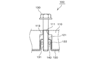
本発明の一実施例である伝動装置用テンショナユニット100は、図1、図2に示すように、テンショナ本体110と、該テンショナ本体110と被取付部材であるエンジンブロックEの間に挟まれるガスケット120と、テンショナ本体110に設けられた取付孔111およびガスケット120に設けられたボルト孔121に挿入されてテンショナ本体110をエンジンブロックEに固定する固定ボルト130からなっている。
Below, the tensioner unit for transmission devices which is one Example of this invention is demonstrated based on drawing.
As shown in FIGS. 1 and 2, a transmission
前述したガスケット120のボルト孔121は、テンショナ本体110の取付孔111に挿入される円筒状の挿入凸部122の先端に設けられており、テンショナ本体110の取付孔111のエンジンブロックE側には、挿入凸部122が挿入される取付孔大径部113が設けられている。
The
そして、図1に示すように、ガスケット120とテンショナ本体110が挿入凸部122が取付孔大径部113に挿入されることで位置合わせして重ねられ、外径が挿入凸部122の内径より大きく内径が固定ボルト130のネジ山131の外径より小さいOリング140が挿入凸部122に挿入され、さらに、固定ボルト130が挿入されてOリング140の弾性によって挿入凸部122に固定されることで、テンショナ本体110、ガスケット120および固定ボルト130が位置決めされた状態で一体に供給可能となっている。
なお、前述した挿入凸部122およびOリング140の数は、少なくとも1か所以上であれば、それぞれ、何か所であっても良い。
As shown in FIG. 1, the
In addition, as long as the number of the above-mentioned insertion
そして、図2に示すように、伝動装置用テンショナユニット100を一体のままエンジンブロックEに締め付け固定することで、煩雑な作業なしにガスケット120の位置決め精度を確実に確保することができ、固定ボルト130の締付圧がガスケット120のボルト孔121の周囲に均等かかるため、ガスケット120のシール性が向上するとともに、ガスケット120の偏った変形が発生せず、メンテナンス等で分解した際にもガスケット120の再利用が可能となっている。
Then, as shown in FIG. 2, by tightening and fixing the
また、図3、4に示すように、ガスケット120の挿入凸部122に放射状に複数のスリット123を設け、取付孔大径部113の内面方向に広がるように弾性が付与されても良く、そうすることで、固定ボルト130が挿入されていない状態でもテンショナ本体110とガスケット120が一体に保持されるため、組み付け前に伝動装置用テンショナユニット100を一体化する作業がさらに容易となるとともに、テンショナ本体110とガスケット120との位置関係をさらに正確に確保することができる。
Also, as shown in FIGS. 3 and 4, a plurality of
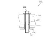
本発明をより良く理解するための第2参考例である伝動装置用テンショナユニット200は、図5に示すように、テンショナ本体210と、該テンショナ本体210と被取付部材であるエンジンブロックEの間に挟まれるガスケット220と、テンショナ本体210に設けられた取付孔211およびガスケット220に設けられたボルト孔に挿入されてテンショナ本体210をエンジンブロックEに固定する固定ボルト230からなっている。
As shown in FIG. 5, a
ガスケット220のボルト孔は、テンショナ本体210の取付孔211に挿入される円筒状の挿入凸部222の先端部に設けられ、ボルト孔の内周部には固定ボルト230のネジ山231に係合する係合片224が設けられており、固定ボルト230が挿入されて係合片224が固定ボルト230のネジ山231に係合することで、テンショナ本体210、ガスケット220および固定ボルト230が位置決めされた状態で一体に供給可能となっている。
The bolt hole of the
そして、伝動装置用テンショナユニット200を一体のままエンジンブロックEに締め付け固定することで、煩雑な作業なしにガスケット220の位置決め精度を確実に確保し、固定ボルト230の締付圧がガスケット220のボルト孔の周囲に均等かかるため、ガスケット220のシール性が向上し、ガスケット220の偏った変形が発生せず、メンテナンス等で分解した際にもガスケット220の再利用が可能となっている。
Then, by tightening and fixing the
また、挿入凸部222はテンショナ本体210の取付孔211の内周に密着するように構成されることで、固定ボルト230が挿入されていない状態でもテンショナ本体210とガスケット220が一体に保持されるため、組み付け前に伝動装置用テンショナユニット200を一体化する作業がさらに容易となるとともに、テンショナ本体210とガスケット220との位置関係をさらに正確に確保している。
Further, the insertion
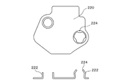
なお、挿入凸部222の形状は、図5、図7、図8に示すように、単純な円筒形状としても良く、図6に示すように、中央部で膨らむような鼓形状としても良い。
また、係合片224の形状は、図5に示すように、水平に突出させても良く、図6、図7に示すように、上方に傾斜して設けても良く、図8に示すように、下方に傾斜して設けても良い。
In addition, the shape of the insertion
Further, the shape of the
また、挿入凸部222および係合片224の形状、および組み合わせは、固定ボルト230が挿入されて係合片224が固定ボルト230のネジ山231に係合することで、テンショナ本体210、ガスケット220および固定ボルト230が位置決めされるものであれば、図5乃至図8に例示したものに限定されず、いかなる形状、組み合わせでも良い。
Further, the shape and combination of the insertion
また、ガスケット220に2か所以上のボルト孔がある場合、図9に示すように、少なくとも1か所以上に挿入凸部222および係合片224が設けられていれば良く、その数はそれぞれ、何か所であっても良い。
In addition, when the
本発明をより良く理解するための第2参考例である伝動装置用テンショナユニット300は、図10に示すように、テンショナ本体310と、該テンショナ本体310と被取付部材であるエンジンブロックEの間に挟まれるガスケット320と、テンショナ本体310に設けられた取付孔311およびガスケット320に設けられたボルト孔に挿入されてテンショナ本体310をエンジンブロックEに固定する固定ボルト330から構成されている。
As shown in FIG. 10, a
ガスケット320は、芯材となる薄板327の両表面にシール性の高いコーティング層325を有してなり、ボルト孔の内周部には、抜け止め部326が、コーティング層325を固定ボルト330のネジ山331の外径より小さい内径となるように膨出させて形成されており、固定ボルト330が挿入されて抜け止め部326が固定ボルト330のネジ山331に係合することで、テンショナ本体310、ガスケット320および固定ボルト330が位置決めされた状態で一体に供給可能となっている。
The
そして、伝動装置用テンショナユニット300を一体のままエンジンブロックEに締め付け固定することで、煩雑な作業なしにガスケット320の位置決め精度を確実に確保することができ、固定ボルト330の締付圧がガスケット320のボルト孔321の周囲に均等かかるため、ガスケット320のシール性が向上するとともに、ガスケット320の偏った変形が発生せず、メンテナンス等で分解した際にもガスケット320の再利用が可能となっている。
Then, by tightening and fixing the
また、図11に示すように、ガスケット320のコーティング層325を、テンショナ本体310の取付孔311に挿入される円筒状の挿入凸部322を形成し、さらにその先端に抜け止め部326を固定ボルト330のネジ山331の外径より小さい内径となるように膨出させて形成しても良い。
Further, as shown in FIG. 11, the
そして、挿入凸部322をテンショナ本体310の取付孔311の内周に密着する外径とすることで、固定ボルト330が挿入されていない状態でもテンショナ本体310とガスケット320が一体に保持されるため、組み付け前に伝動装置用テンショナユニット300を一体化する作業がさらに容易となるとともに、テンショナ本体310とガスケット320との位置関係をさらに正確に確保している。
And since the insertion
なお、第1参考例の係合片224および第2参考例の抜け止め部326のネジ山231、331と係合する先端部の形状は、固定ボルト230、330が固定位置決めされるとともに、締め付け作業を妨げないものであれば、図12、図13、図14に示すような、断面円形、断面先端凸形状、断面先端凹形状等、いかなる形状であっても良い。
Note that the shapes of the front end portions engaged with the
以上のように、本発明の伝動装置用テンショナユニットによれば、簡単な構成で、組み付け時の作業を容易にするとともに、ガスケットの位置決め精度を確実に確保してシール性を向上し、ガスケットの再利用を可能とすることができる。 As described above, according to the tensioner unit for a transmission device of the present invention, the work at the time of assembly is facilitated with a simple configuration, and the gasket positioning accuracy is ensured to improve the sealing performance. Can be reused.
100・・・伝動装置用テンショナユニット
110・・・テンショナ本体
111・・・取付孔
113・・・取付孔大径部
120・・・ガスケット
121・・・ボルト孔
122・・・挿入凸部
123・・・スリット
130・・・固定ボルト
131・・・ネジ山
140・・・Oリング
200、300、500・・・伝動装置用テンショナユニット
210、310、510・・・テンショナ本体
211、311、511・・・取付孔
512 ・・・プランジャ
220、320、520・・・ガスケット
221、321、521・・・ボルト孔
222、322・・・挿入凸部
224・・・係合片
325・・・コーティング層
326・・・抜け止め部
230、330、530・・・固定ボルト
231、331・・・ネジ山
E ・・・エンジンブロック
DESCRIPTION OF
Claims (1)
前記ガスケットのボルト孔が、前記テンショナ本体の取付孔に挿入される円筒状の挿入凸部の先端に設けられ、
前記挿入凸部が、前記テンショナ本体の取付孔の内面方向に広がって弾性が付与されるように放射状に複数のスリットを有し、
前記ボルト保持機構が、前記挿入凸部の内径より大きな外径と前記固定ボルトのネジ山の外径より小さな内径のOリングと前記挿入凸部とで構成されていることを特徴とする伝動装置用テンショナユニット。 A gasket sandwiched between the tensioner body and the member to be attached; a fixing bolt for fixing the tensioner body to the member to be attached by being inserted into the mounting hole of the tensioner body and the bolt hole of the gasket; and In the tensioner unit for a transmission device having a bolt holding mechanism for holding a fixing bolt inserted into the bolt hole of the gasket in a state where the gasket is aligned and overlapped with the tensioner body,
The bolt hole of the gasket is provided at the tip of a cylindrical insertion convex portion inserted into the attachment hole of the tensioner body,
The insertion convex portion has a plurality of slits radially so that elasticity is imparted by spreading toward the inner surface of the attachment hole of the tensioner body,
The transmission device characterized in that the bolt holding mechanism includes an O-ring having an outer diameter larger than an inner diameter of the insertion convex portion, an inner diameter smaller than an outer diameter of a screw thread of the fixing bolt, and the insertion convex portion. Tensioner unit.
Priority Applications (4)
| Application Number | Priority Date | Filing Date | Title |
|---|---|---|---|
| JP2009289304A JP4987955B2 (en) | 2009-12-21 | 2009-12-21 | Tensioner unit for transmission |
| US12/963,188 US20110152022A1 (en) | 2009-12-21 | 2010-12-08 | Tensioner unit |
| KR1020100128339A KR101411090B1 (en) | 2009-12-21 | 2010-12-15 | Tensioner unit |
| CN2010106107004A CN102109030A (en) | 2009-12-21 | 2010-12-16 | Tensioner unit |
Applications Claiming Priority (1)
| Application Number | Priority Date | Filing Date | Title |
|---|---|---|---|
| JP2009289304A JP4987955B2 (en) | 2009-12-21 | 2009-12-21 | Tensioner unit for transmission |
Publications (2)
| Publication Number | Publication Date |
|---|---|
| JP2011127741A JP2011127741A (en) | 2011-06-30 |
| JP4987955B2 true JP4987955B2 (en) | 2012-08-01 |
Family
ID=44151890
Family Applications (1)
| Application Number | Title | Priority Date | Filing Date |
|---|---|---|---|
| JP2009289304A Active JP4987955B2 (en) | 2009-12-21 | 2009-12-21 | Tensioner unit for transmission |
Country Status (4)
| Country | Link |
|---|---|
| US (1) | US20110152022A1 (en) |
| JP (1) | JP4987955B2 (en) |
| KR (1) | KR101411090B1 (en) |
| CN (1) | CN102109030A (en) |
Families Citing this family (4)
| Publication number | Priority date | Publication date | Assignee | Title |
|---|---|---|---|---|
| JP6408251B2 (en) * | 2014-05-22 | 2018-10-17 | 三菱アルミニウム株式会社 | Dive prevention device |
| US10975823B2 (en) * | 2019-08-16 | 2021-04-13 | Caterpillar Inc. | Fastener-component sub-assembly |
| JP7448811B2 (en) | 2020-05-25 | 2024-03-13 | 株式会社椿本チエイン | chain guide |
| JP2022108042A (en) | 2021-01-12 | 2022-07-25 | 株式会社椿本チエイン | chain guide |
Family Cites Families (13)
| Publication number | Priority date | Publication date | Assignee | Title |
|---|---|---|---|---|
| US5544902A (en) * | 1994-06-30 | 1996-08-13 | Dana Corporation | Metal gasket with bolt retention freature |
| JPH0932893A (en) * | 1995-07-20 | 1997-02-04 | Suzuki Motor Corp | Chain tensioner for internal combustion engine |
| JPH09126216A (en) * | 1995-10-27 | 1997-05-13 | Taiko:Kk | Bolt falling-off preventive device for piping support ring-shaped member |
| JPH09177751A (en) * | 1995-12-25 | 1997-07-11 | Taiko:Kk | Clamping bolt capable of being prevented from dropping |
| JP3326683B2 (en) * | 1997-09-24 | 2002-09-24 | 株式会社フジキン | Bolt retaining device |
| JP2002031239A (en) * | 2000-07-14 | 2002-01-31 | Mitsubishi Cable Ind Ltd | Annular seal |
| JP4672838B2 (en) * | 2000-08-30 | 2011-04-20 | サンデン商事株式会社 | Manufacturing method of gasket |
| JP3586774B2 (en) * | 2002-04-12 | 2004-11-10 | 株式会社フジキン | Bolt retaining device |
| JP4540974B2 (en) * | 2003-12-16 | 2010-09-08 | Ntn株式会社 | Auxiliary machine belt tension adjuster |
| KR20070049672A (en) * | 2004-08-23 | 2007-05-11 | 씨케이디 가부시키 가이샤 | Bolt falling preventive structure and hold ring |
| JP3967351B2 (en) * | 2004-10-20 | 2007-08-29 | 株式会社椿本チエイン | Tensioner with bent stopper pin |
| JP5003934B2 (en) * | 2006-09-07 | 2012-08-22 | 内山工業株式会社 | gasket |
| CN100564944C (en) * | 2007-08-09 | 2009-12-02 | 力帆实业(集团)股份有限公司 | A kind of petrolic chain tension system |
-
2009
- 2009-12-21 JP JP2009289304A patent/JP4987955B2/en active Active
-
2010
- 2010-12-08 US US12/963,188 patent/US20110152022A1/en not_active Abandoned
- 2010-12-15 KR KR1020100128339A patent/KR101411090B1/en active IP Right Grant
- 2010-12-16 CN CN2010106107004A patent/CN102109030A/en active Pending
Also Published As
| Publication number | Publication date |
|---|---|
| KR101411090B1 (en) | 2014-06-27 |
| US20110152022A1 (en) | 2011-06-23 |
| CN102109030A (en) | 2011-06-29 |
| JP2011127741A (en) | 2011-06-30 |
| KR20110073280A (en) | 2011-06-29 |
Similar Documents
| Publication | Publication Date | Title |
|---|---|---|
| JP4987955B2 (en) | Tensioner unit for transmission | |
| US9927051B2 (en) | Seal holding device for pipe clamp | |
| JP2008095960A (en) | Hose clamp | |
| JP2006234022A (en) | Holding structure of hose clamp | |
| US20130071179A1 (en) | Fastening Device for Attachment to a Mounting Rail | |
| JP2009537748A (en) | Pull rail or guide rail with fixing means to hold the bolt | |
| RU2697585C2 (en) | Sealing device | |
| US10047696B2 (en) | Cover structure for internal combustion engine | |
| JP6156412B2 (en) | Internal combustion engine | |
| US20070262538A1 (en) | Cylinder head gasket | |
| AU2017268298A1 (en) | Direct tension indicating apparatus | |
| US20140252724A1 (en) | Self-retaining gasket | |
| WO2016021433A1 (en) | Sealing device | |
| US20190003558A1 (en) | Chain guide assembly for an internal combustion engine | |
| JP2012017814A (en) | Loosening-prevention screwing structure | |
| JP2009075272A (en) | Microscope objective lens | |
| JP2019044608A (en) | Cover fastening structure of internal combustion engine | |
| WO2017038817A1 (en) | Positioning structure for cylinder head cover | |
| JP2004027821A (en) | Wedge for anchoring pc steel | |
| WO2011111279A1 (en) | Mechanical seal | |
| JPS62233507A (en) | Holder | |
| JP7233934B2 (en) | leak prevention device | |
| JP2023092751A (en) | Mechanical seal device | |
| CN108621783B (en) | Fixing device and motor vehicle with same | |
| WO2021005995A1 (en) | Gasket |
Legal Events
| Date | Code | Title | Description |
|---|---|---|---|
| A621 | Written request for application examination |
Free format text: JAPANESE INTERMEDIATE CODE: A621 Effective date: 20110922 |
|
| A977 | Report on retrieval |
Free format text: JAPANESE INTERMEDIATE CODE: A971007 Effective date: 20120120 |
|
| A131 | Notification of reasons for refusal |
Free format text: JAPANESE INTERMEDIATE CODE: A131 Effective date: 20120124 |
|
| A521 | Written amendment |
Free format text: JAPANESE INTERMEDIATE CODE: A523 Effective date: 20120214 |
|
| TRDD | Decision of grant or rejection written | ||
| A01 | Written decision to grant a patent or to grant a registration (utility model) |
Free format text: JAPANESE INTERMEDIATE CODE: A01 Effective date: 20120424 |
|
| A01 | Written decision to grant a patent or to grant a registration (utility model) |
Free format text: JAPANESE INTERMEDIATE CODE: A01 |
|
| A61 | First payment of annual fees (during grant procedure) |
Free format text: JAPANESE INTERMEDIATE CODE: A61 Effective date: 20120425 |
|
| R150 | Certificate of patent or registration of utility model |
Free format text: JAPANESE INTERMEDIATE CODE: R150 Ref document number: 4987955 Country of ref document: JP Free format text: JAPANESE INTERMEDIATE CODE: R150 |
|
| FPAY | Renewal fee payment (event date is renewal date of database) |
Free format text: PAYMENT UNTIL: 20150511 Year of fee payment: 3 |