JP4987423B2 - Magnetic resonance imaging system - Google Patents
Magnetic resonance imaging system Download PDFInfo
- Publication number
- JP4987423B2 JP4987423B2 JP2006289953A JP2006289953A JP4987423B2 JP 4987423 B2 JP4987423 B2 JP 4987423B2 JP 2006289953 A JP2006289953 A JP 2006289953A JP 2006289953 A JP2006289953 A JP 2006289953A JP 4987423 B2 JP4987423 B2 JP 4987423B2
- Authority
- JP
- Japan
- Prior art keywords
- imaging
- range
- magnetic resonance
- imaging range
- interest
- Prior art date
- Legal status (The legal status is an assumption and is not a legal conclusion. Google has not performed a legal analysis and makes no representation as to the accuracy of the status listed.)
- Expired - Fee Related
Links
Images


Description
本発明は、オペレータにより指定された関心領域に関する画像を得る磁気共鳴イメージング装置に関する。 The present invention relates to a magnetic resonance imaging apparatus that obtains an image related to a region of interest designated by an operator.
従来、磁気共鳴イメージング装置(以下、MRI装置と称する)における撮像範囲(以下、FOVと称する)の位置決めには、位置決め用の基準画像上で指定される関心領域(以下、ROIと称する)を判定することにより行われる。MRI装置は、1回の撮像における撮像可能範囲には限りがあるので、この撮像可能範囲を超えない範囲でROIの指定可能としている。 Conventionally, in the positioning of an imaging range (hereinafter referred to as FOV) in a magnetic resonance imaging apparatus (hereinafter referred to as MRI apparatus), a region of interest (hereinafter referred to as ROI) designated on a reference image for positioning is determined. Is done. Since the MRI apparatus has a limited imaging range in one imaging, the ROI can be specified within a range not exceeding the imaging range.
一方、近年は、複数回の撮像により得られた複数の画像をつなぎ合わせて大きな範囲の画像を得ることが考えられている。この場合、オペレータは各回の撮像範囲をROIの指定により個別に定めるようになっている。 On the other hand, in recent years, it has been considered to obtain a large range of images by connecting a plurality of images obtained by a plurality of imaging operations. In this case, the operator individually determines the imaging range for each time by specifying the ROI.
FOVの設定方法に関しては、特許文献1〜6のようなものが知られている。
ところが上記のような従来のMRI装置では、ある断面での撮像を1回の撮像可能範囲を超えて行いたい場合、オペレータは複数のROIを所望の断面に合わせて適切に指定しなければならない。撮像回数が多いほどそれによる作業は多くなり、作業が煩雑になる。 However, in the conventional MRI apparatus as described above, when it is desired to perform imaging in a certain section beyond the range where imaging can be performed once, the operator must appropriately specify a plurality of ROIs in accordance with a desired section. The greater the number of times of imaging, the more work is required and the work becomes complicated.
本発明はこのような事情を考慮してなされたものであり、その目的とするところは、撮像可能範囲を超える範囲の画像の撮像に係るオペレータの負担を軽減することにある。 The present invention has been made in consideration of such circumstances, and an object of the present invention is to reduce an operator's burden associated with capturing an image in a range exceeding the captureable range.
一態様による磁気共鳴イメージング装置は、静磁場中の被検体に対して傾斜磁場および高周波パルスを印加することで磁気共鳴信号を発生させる撮像部と、前記被検体を載置するための天板を含み、この天板をその長手方向にスライドさせる寝台と、前記磁気共鳴信号を検出するための高周波コイルと、位置決め画像を表示する表示手段と、それぞれが前記静磁場により規定される撮像可能領域より小さい複数の撮像範囲を判定する判定手段と、前記複数の撮像範囲のうちの少なくとも1つを移動させるとともに、当該先に移動させた撮像範囲とは別の撮像範囲を、前記先に移動させた撮像範囲に対して規定状態となるように移動させる移動手段と、前記複数の撮像範囲を確定する確定手段と、前記確定手段により確定された前記複数の撮像範囲をそれぞれ撮像するように前記撮影部、前記寝台および前記高周コイルを制御する制御手段とを具備し、前記判定手段は、前記位置決め画像上での指定に基づいて1つの関心領域を判定する手段と、前記静磁場により規定される撮像可能領域と前記関心領域とで大きさを比較する比較手段と、前記比較手段により前記関心領域が前記撮像可能領域よりも大きいと判定された場合に、前記関心領域を含む複数の撮像範囲を求める演算手段とをさらに具備し、前記確定手段は、前記比較手段により前記関心領域の大きさが前記撮像可能領域の大きさ以下であると判定された場合には、前記関心領域と同じ1つの撮像範囲のみを確定し、それ以外の場合には前記演算手段が求めた複数の撮像範囲をそれぞれ確定し、前記制御手段は、前記確定手段が1つの撮像範囲のみを確定した場合には当該1つの撮像範囲のみを撮像するように、また前記確定手段が複数の撮像範囲をそれぞれ確定した場合には当該複数の撮像範囲をそれぞれ撮像するように前記撮影部、前記寝台および前記高周波コイルを制御する。 A magnetic resonance imaging apparatus according to an aspect includes an imaging unit that generates a magnetic resonance signal by applying a gradient magnetic field and a high-frequency pulse to a subject in a static magnetic field, and a top plate for placing the subject. A bed that slides the top plate in the longitudinal direction thereof, a high-frequency coil for detecting the magnetic resonance signal, a display means for displaying a positioning image, and an imageable region each defined by the static magnetic field. A determination unit that determines a plurality of small imaging ranges and at least one of the plurality of imaging ranges is moved, and an imaging range that is different from the imaging range that has been moved to the destination is moved to the destination Moving means for moving the imaging range so as to be in a prescribed state, determining means for determining the plurality of imaging ranges, and the plurality of imaging determined by the determining means The imaging unit to image enclose respectively, and control means for controlling the bed and said high-frequency coil, said determining means determines one region of interest based on the specified on the positioning image Means, a comparison means for comparing the size of the imageable region defined by the static magnetic field and the region of interest, and the comparison unit determines that the region of interest is larger than the imageable region, A calculation unit that obtains a plurality of imaging ranges including the region of interest, and the determination unit determines that the size of the region of interest is equal to or less than the size of the imageable region by the comparison unit Includes determining only one imaging range that is the same as the region of interest, and otherwise determining each of a plurality of imaging ranges obtained by the calculation unit. When only one imaging range is determined, only the one imaging range is imaged. When the determining means determines a plurality of imaging ranges, the plurality of imaging ranges are respectively captured. The imaging unit, the bed, and the high-frequency coil are controlled .
本発明によれば、撮像可能範囲を超える範囲の画像の撮像に係るオペレータの負担を軽減することができる。 According to the present invention, it is possible to reduce an operator's burden associated with capturing an image in a range that exceeds the captureable range.
以下、図面を参照して本発明の実施形態について説明する。 Hereinafter, embodiments of the present invention will be described with reference to the drawings.
図1は本実施形態に係るMRI装置のブロック図である。このMRI装置は、静磁場発生用の磁石部と、静磁場に位置情報を与えるための傾斜磁場発生用の傾斜磁場部と、磁気励起およびNMR(nuclear magnetic resonance)信号受信のための送・受信部と、システムコントロールおよびデータ処理用の制御・演算部とを機能的に有する。 FIG. 1 is a block diagram of an MRI apparatus according to this embodiment. This MRI apparatus includes a magnet section for generating a static magnetic field, a gradient magnetic field section for generating a gradient magnetic field for providing position information to the static magnetic field, and transmission / reception for receiving magnetic excitation and NMR (nuclear magnetic resonance) signals. And a control / arithmetic unit for system control and data processing.
具体的には、図1に示すように、磁石部は、例えば常電導方式の磁石1と、この磁石1に電流を供給する静磁場電源2とを備え、被検体Pが挿入される開口部のz軸方向に静磁場H0を発生させる。
Specifically, as illustrated in FIG. 1, the magnet unit includes, for example, a normal conducting
傾斜磁場部は、磁石1に組み込まれたx,y,z方向の3対の傾斜磁場コイル4と、これらの傾斜磁場コイル4に電流を供給する駆動回路5および傾斜磁場制御装置6から成る傾斜磁場電源とを備える。傾斜磁場制御装置6は、メインの制御装置7から供給されるパルスシーケンスに応じて駆動回路5を作動させる。これにより、イメージング用の位置情報を付与するため、静磁場H0に線形磁場を重畳させて、傾斜磁場が形成される。
The gradient magnetic field unit is composed of three pairs of
送・受信部は、磁石1の開口部内で、被検体Pに対向して配設される送信コイル8aおよび受信コイル8bと、この送信コイル8aおよび受信コイル8bに個々に接続された送信機9および受信機10とを備える。送信機9は、NMRを励起するための高周波パルスを制御装置7の指令に基づいて発生する。受信機10は、受信コイル8bで得られたNMR信号を検波・増幅し、そのNMR信号を制御装置7の指令に基づいて記憶装置11に送る。
The transmission / reception unit includes a
制御・演算部は、制御装置7、記憶装置11、演算装置12、表示装置13および入力器14を備える。記憶装置11は、NMR信号を記憶する。演算装置12は、制御装置7に動作指令を与える。また演算装置12は、記憶装置11に記憶されたNMR信号をフーリエ変換などを含む演算処理にかけて、画像データを生成する。表示装置13は、演算装置12で生成された画像データが表す画像や、オペレータに通知するべき各種の情報を演算装置12の制御の下に表示する。入力器14は、例えばキーボードやマウスなどを含み、オペレータによる各種の指定を入力する。
The control / arithmetic unit includes a control device 7, a
以上が本実施形態に係るMRI装置の基本的な構成である。 The above is the basic configuration of the MRI apparatus according to the present embodiment.
(第1の実施形態)
第1の実施形態において演算装置12は、以下のようないくつかの機能をさらに備える。第1の機能は、入力器14での操作により指定されるROIを判定する。この第1の機能は、1回の撮像可能範囲に拘わらずにROIの指定を受け付ける。第2の機能は、入力器14での操作によりROI中に指定される関心点を判定する。第3の機能は、指定されたROIが撮像可能範囲よりも大きい場合に、ROIの全てを包含するように複数の撮像範囲を設定する。この第3の機能は、上記の関心点が指定されている場合には、その関心点を1つの撮像範囲の中央とするように前記複数の撮像範囲を設定する。第4の機能は、上記の複数の撮像範囲のそれぞれに関する撮像を行うように制御装置7に指令し、この複数回の撮像により得られた複数の画像をつなぎ合わせてROIに関する画像データを生成する。
(First embodiment)
In the first embodiment, the
次に以上のように構成された第1の実施形態のMRI装置の動作について説明する。 Next, the operation of the MRI apparatus of the first embodiment configured as described above will be described.
図2は第1の実施形態における演算装置12の処理手順を示すフローチャートである。
FIG. 2 is a flowchart showing a processing procedure of the
ステップSa1において演算装置12は、予め準備した例えば図3に示すような基準画像を表示装置13に表示させる。基準画像は例えば、寝台位置を変化させながら広範囲を高速に収集したNMR信号に基づいて再構成する。
In step Sa1, the
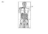
オペレータは、基準画像を確認しながら入力器14を操作して、高精細な撮像を行うべき領域をROIとして指定する。そこでステップSa2において演算装置12は、入力器14からの出力情報に基づいて、指定されているROIを判定する。このときに演算装置12は、ROIの大きさを制限しない。演算装置12は判定したROIを、例えば図4に符号21を付して示すように基準画像に重ねて表示させる。
The operator operates the
ステップSa3乃至ステップSa5において演算装置12は、ROIの変更、関心点の指定および撮像開始のいずれかのイベントが発生するのを待ち受ける。
In steps Sa3 to Sa5, the
オペレータは、一旦指定したROIを入力器14を操作して必要に応じて変更する。このようなROIを変更する操作がなされたならば、演算装置12はステップSa3からステップSa2に戻り、変更後のROIを判定する。
The operator changes the ROI once designated by operating the
オペレータは、入力器14を操作してROIの中に関心点を指定することもできる。関心点を指定する操作がなされたならば、演算装置12はステップSa4からステップSa6へ進む。ステップSa6において演算装置12は、指定された関心点を判定する。こののちに演算装置12は、ステップSa3乃至ステップSa5の待ち受け状態に戻る。
The operator can also operate the
オペレータは、ROIを指定し終えたならば、入力器14を操作して撮像開始を指示する。このように撮像開始が指示されたことに応じて演算装置12は、ステップSa5からステップSa7へ進む。ステップSa7において演算装置12は、その時点で判定していたROIが撮像可能範囲よりも大きいか否かを確認する。ROIが撮像可能範囲よりも大きいならば、演算装置12はステップSa7からステップSa8へ進む。ステップSa8において演算装置12は、ROIの全てを包含するように複数の撮像範囲を設定する。演算装置12は、ステップSa6で関心点を判定しているならば、その関心点が1つの撮像範囲の中心に位置するように撮像範囲を設定する。なお撮像範囲は、隣接するものどうしの一部を重複させることが望ましい。図5は図4に示すように指定されたROIに関する撮像範囲の設定の例を示す図である。この図5では、3つの撮像範囲31,32,33が設定されている。そして撮像範囲31と撮像範囲32、あるいは撮像範囲32と撮像範囲33とは、それぞれ一部が重複している。
When the operator has finished specifying the ROI, he / she operates the
ステップSa9において演算装置12は、制御装置7に指令を送り、ステップSa8で設定した各撮像範囲の撮像を行わせる。ステップSa10において演算装置12は、収集されたNMR信号に基づいて各撮像範囲の画像を再構成するとともに、これらの再構成画像をつなぎ合わせてROIに相当する再構成画像を生成する。
In step Sa9, the
一方、ROIが撮像可能範囲よりも小さいならば、演算装置12はステップSa7からステップSa11へ進む。ステップSa11において演算装置12は、ROIをそのまま撮像範囲に設定する。
On the other hand, if the ROI is smaller than the imageable range, the
ステップSa12において演算装置12は、制御装置7に指令を送り、ステップSa11で設定した撮像範囲の撮像を行わせる。ステップSa13において演算装置12は、収集されたNMR信号に基づいて撮像範囲の画像を再構成する。
In step Sa12, the
このように第1の実施形態によれば、撮像可能範囲を超えた範囲に関する再構成画像を得たい場合であっても、オペレータは1つのROIを指定すれば良く、複数のROIを指定しなければならない場合に比べてオペレータの負担を軽減することができる。 As described above, according to the first embodiment, even when it is desired to obtain a reconstructed image relating to a range that exceeds the imageable range, the operator only needs to specify one ROI and must specify a plurality of ROIs. The burden on the operator can be reduced compared with the case where it is necessary.
また第1の実施形態によれば、位置決めスキャンのスループットを著しく改善することができる。すなわち、1つのROIを複数に分割して複数の撮像範囲が設定されるので、これら複数の撮像範囲の相対位置を、各撮像範囲に関する再構成画像をつなぎ合わせるのに適正に維持することがき、つなぎ合わせの精度を高めることができる。 Further, according to the first embodiment, the positioning scan throughput can be remarkably improved. That is, since a plurality of imaging ranges are set by dividing one ROI into a plurality, the relative positions of the plurality of imaging ranges can be properly maintained to connect the reconstructed images related to the imaging ranges, The accuracy of joining can be increased.
(第2の実施形態)
第2の実施形態において演算装置12は、以下のようないくつかの機能をさらに備える。第1の機能は、入力器14での操作により平行に指定される複数のROIを判定する。この第1の機能は、1つのROIを撮像可能範囲を超えないように制限する。第2の機能は、入力器14での操作による移動指定に応じて、複数のROIの1つを移動させる。第2の機能はさらに、移動させたROIとは別のROIを、移動されたROIに第1の機能により判定されたのと同様な状態で平行するように移動させる。第3の機能は、上記の複数の撮像範囲のそれぞれに関する撮像を行うように制御装置7に指令し、この複数回の撮像により得られた複数の画像をつなぎ合わせてROIに関する画像データを生成する。
(Second Embodiment)
In the second embodiment, the
次に以上のように構成された第2の実施形態のMRI装置の動作について説明する。 Next, the operation of the MRI apparatus according to the second embodiment configured as described above will be described.
図6は第2の実施形態における演算装置12の処理手順を示すフローチャートである。
FIG. 6 is a flowchart showing a processing procedure of the
ステップSb1において演算装置12は、予め準備した例えば図3に示すような基準画像を表示装置13に表示させる。
In step Sb1, the
オペレータは、基準画像を確認しながら入力器14を操作して、高精細な撮像を行うべき領域をROIとして指定する。そこでステップSb2において演算装置12は、入力器14からの出力情報に基づいて、指定されているROIを判定する。このときに演算装置12は、ROIの大きさを撮像可能範囲よりも大きくならないように制限する。
The operator operates the
続いて演算装置12は、ステップSb3乃至ステップSb5の待ち受け状態に移行する。この待ち受け状態において演算装置12は、ROIの変更、新しいROIの指定および撮像開始のいずれかのイベントが発生するのを待ち受ける。
Subsequently, the
オペレータは、一旦指定したROIを入力器14を操作して必要に応じて変更する。このようなROIを変更する操作がなされたならば、演算装置12はステップSb3からステップSb2に戻り、変更後のROIを判定する。
The operator changes the ROI once designated by operating the
オペレータは、入力器14を操作して新しいROIを必要に応じて指定する。このような新たなROIを指定する操作がなされたならば、演算装置12はステップSb4からステップSb6へ進む。ステップSb6において演算装置12は、入力器14からの出力情報に基づいて、新たに指定されたROIを判定する。
The operator operates the
こののちに演算装置12は、ステップSb7乃至ステップSb9の待ち受け状態に移行する。この待ち受け状態において演算装置12は、ROIの変更、新しいROIの指定および撮像開始のいずれかのイベントが発生するのを待ち受ける。
Thereafter, the
オペレータは、入力器14を操作して、さらに別の新しいROIを必要に応じて指定することができる。このような新たなROIを指定する操作がなされたならば、演算装置12はステップSb8からステップSb6へ戻り、新たに指定されたROIを判定する。なお、ROIの数に限度数を定め、この限度数を超えない範囲でROIの指定を受け付けるようにしても良い。
The operator can operate the
オペレータは、指定した複数のROIのうちの1つを入力器14を操作して必要に応じて変更する。このようなROIを変更する操作がなされたならば、演算装置12はステップSb7からステップSb10に進む。ステップSb10において演算装置12は、変更後のROIを判定する。次にステップSb11において演算装置12は、上記の変更したROIとは別のROIを、変更したROIと平行になるように変更する。例えば、図7に示すように3つのROI41,42,43が設定されている状態から、ROI42が図8に示すように回転されたとする。この場合に演算装置12は、ROI41,43をROI42に平行させるように回転および移動させ図9に示すような状態とする。このときに演算装置12は、元のROI41,42,43が図7に示すように重複しているならば、図9に示すようにその重複を変更後にも再現する。全てのROIを変更し終えたならば、演算装置12はステップSb6乃至ステップSb8の待ち受け状態に戻る。
The operator operates the
なお演算装置12は、以上のように設定しているROIを、例えば図7乃至図9に示すように基準画像に重ねて表示させる。
Note that the
オペレータは、ROIを指定し終えたならば、入力器14を操作して撮像開始を指示する。演算装置12は、ステップSb7乃至ステップSb9の待ち受け状態にあるときに撮像開始が指示されたならば、ステップSb9からステップSb12へ進む。ステップSb12において演算装置12は、その時点で判定していたROIをそれぞれ撮像範囲に設定する。
When the operator has finished specifying the ROI, he / she operates the
ステップSb13において演算装置12は、制御装置7に指令を送り、ステップSb12で設定した各撮像範囲の撮像を行わせる。ステップSb14において演算装置12は、収集されたNMR信号に基づいて各撮像範囲の画像を再構成するとともに、これらの再構成画像をつなぎ合わせてROIに相当する再構成画像を生成する。
In step Sb13, the
一方、演算装置12は、ステップSb3乃至ステップSb5の待ち受け状態にあるときに撮像開始が指示されたならば、ステップSb5からステップSb15へ進む。ステップSb15において演算装置12は、ROIをそのまま撮像範囲に設定する。
On the other hand, if the
ステップSb16において演算装置12は、制御装置7に指令を送り、ステップSb15で設定した撮像範囲の撮像を行わせる。ステップSb17において演算装置12は、収集されたNMR信号に基づいて撮像範囲の画像を再構成する。
In step Sb16, the
このように第2の実施形態によれば、撮像可能範囲を超える範囲の再構成画像を得ようとするときには、オペレータは複数のROIを指定する必要がある。しかしながら、これら複数のROIの平行位置を維持するように自動的に調整されるので、複数のROIの平行位置の微調整をオペレータが手作業で行う必要はない。従って、そのような作業を行わなければならない場合に比べて、オペレータの負担を軽減することができる。 As described above, according to the second embodiment, the operator needs to specify a plurality of ROIs in order to obtain a reconstructed image in a range that exceeds the imageable range. However, since the adjustment is automatically performed so as to maintain the parallel positions of the plurality of ROIs, the operator does not need to finely adjust the parallel positions of the plurality of ROIs. Therefore, the burden on the operator can be reduced as compared with the case where such work must be performed.
また第2の実施形態によれば、位置決めスキャンのスループットを著しく改善することができる。すなわち、複数のROIの平行位置が自動的に維持されるので、複数のROIの相対位置を各撮像範囲に関する再構成画像をつなぎ合わせるのに適正に維持することがき、つなぎ合わせの精度を高めることができる。 According to the second embodiment, the throughput of positioning scan can be remarkably improved. In other words, since the parallel positions of the plurality of ROIs are automatically maintained, the relative positions of the plurality of ROIs can be properly maintained for joining the reconstructed images related to the respective imaging ranges, and the joining accuracy can be improved. Can do.
(第3の実施形態)
第3の実施形態において演算装置12は、以下のようないくつかの機能をさらに備える。第1の機能は、入力器14での操作により平行に指定される複数のROIを判定する。この第1の機能は、1つのROIを撮像可能範囲を超えないように制限する。第2の機能は、入力器14での操作による移動指定に応じて、複数のROIの1つを移動させる。第2の機能はさらに、移動させたROIとは別のROIを、移動されたROIとの重複領域内の基準点の移動に追従させるように変更する。第3の機能は、上記の複数の撮像範囲のそれぞれに関する撮像を行うように制御装置7に指令し、この複数回の撮像により得られた複数の画像をつなぎ合わせてROIに関する画像データを生成する。
(Third embodiment)
In the third embodiment, the
次に以上のように構成された第3の実施形態のMRI装置の動作について説明する。 Next, the operation of the MRI apparatus of the third embodiment configured as described above will be described.
第3の実施形態における演算装置12の処理手順は、図6に示した第2の実施形態における処理手順と同様である。ただし、第3の実施形態では、ステップSb11における処理の内容が異なっている。すなわちステップSb11において演算装置12は、上記の変更したROIとは別のROIを、移動されたROIとの重複領域内の基準点の移動に追従させるように変更する。例えば図10に示すように3つのROI51,52,53が設定されている状態から、ROI52が図11に示すように移動されたとする。この場合に演算装置12は、ROI51,53を基準点61,62の移動に追従させて図12に示すような状態とする。なお基準点61,62は、操作者により指定させても良いし、ROIの重複領域の重心位置などに自動的に設定しても良い。
The processing procedure of the
このように第3の実施形態によれば、撮像可能範囲を超える範囲の再構成画像を得ようとするときには、オペレータは複数のROIを指定する必要がある。しかしながら、これら複数のROIの一部が重複した状態を維持するように自動的に調整されるので、複数のROIの1つを変更した場合に、それに伴う他のROIの変更をオペレータが手作業で行う必要はない。従って、そのような作業を行わなければならない場合に比べて、オペレータの負担を軽減することができる。 As described above, according to the third embodiment, the operator needs to specify a plurality of ROIs when attempting to obtain a reconstructed image in a range that exceeds the imageable range. However, since some of the plurality of ROIs are automatically adjusted so as to maintain an overlapping state, when one of the plurality of ROIs is changed, the operator manually changes other ROIs accompanying the change. There is no need to do this. Therefore, the burden on the operator can be reduced as compared with the case where such work must be performed.
この実施形態は、次のような種々の変形実施が可能である。 This embodiment can be variously modified as follows.
第1の実施形態においては、ROIの一部を包含しないように撮像範囲の設定を行うようにしても良い。 In the first embodiment, the imaging range may be set so as not to include a part of the ROI.
なお、本発明は上記実施形態そのままに限定されるものではなく、実施段階ではその要旨を逸脱しない範囲で構成要素を変形して具体化できる。また、上記実施形態に開示されている複数の構成要素の適宜な組み合わせにより、種々の発明を形成できる。例えば、実施形態に示される全構成要素から幾つかの構成要素を削除してもよい。さらに、異なる実施形態にわたる構成要素を適宜組み合わせてもよい。 Note that the present invention is not limited to the above-described embodiment as it is, and can be embodied by modifying the constituent elements without departing from the scope of the invention in the implementation stage. In addition, various inventions can be formed by appropriately combining a plurality of components disclosed in the embodiment. For example, some components may be deleted from all the components shown in the embodiment. Furthermore, constituent elements over different embodiments may be appropriately combined.
1…磁石、2…静磁場電源、4…傾斜磁場コイル、5…駆動回路、6…傾斜磁場制御装置、7…制御装置、8a…送信コイル、8b…受信コイル、9…送信機、10…受信機、11…記憶装置、12…演算装置、13…表示装置、14…入力器。
DESCRIPTION OF
Claims (7)
前記被検体を載置するための天板を含み、この天板をその長手方向にスライドさせる寝台と、
前記磁気共鳴信号を検出するための高周波コイルと、
それぞれが前記静磁場により規定される撮像可能領域より小さい複数の撮像範囲を判定する判定手段と、
前記複数の撮像範囲のうちの少なくとも1つを移動させるとともに、当該先に移動させた撮像範囲とは別の撮像範囲を、前記先に移動させた撮像範囲に対して規定状態となるように移動させる移動手段と、
前記複数の撮像範囲を確定する確定手段と、
前記確定手段により確定された前記複数の撮像範囲をそれぞれ撮像するように前記撮影部、前記寝台および前記高周波コイルを制御する制御手段とを具備し、
前記判定手段は、
前記位置決め画像上での指定に基づいて1つの関心領域を判定する手段と、
前記静磁場により規定される撮像可能領域と前記関心領域とで大きさを比較する比較手段と、
前記比較手段により前記関心領域が前記撮像可能領域よりも大きいと判定された場合に、前記関心領域を含む複数の撮像範囲を求める演算手段とをさらに具備し、
前記確定手段は、前記比較手段により前記関心領域の大きさが前記撮像可能領域の大きさ以下であると判定された場合には、前記関心領域と同じ1つの撮像範囲のみを確定し、それ以外の場合には前記演算手段が求めた複数の撮像範囲をそれぞれ確定し、
前記制御手段は、前記確定手段が1つの撮像範囲のみを確定した場合には当該1つの撮像範囲のみを撮像するように、また前記確定手段が複数の撮像範囲をそれぞれ確定した場合には当該複数の撮像範囲をそれぞれ撮像するように前記撮影部、前記寝台および前記高周波コイルを制御することを特徴とする磁気共鳴イメージング装置。 An imaging unit that generates a magnetic resonance signal by applying a gradient magnetic field and a high-frequency pulse to a subject in a static magnetic field;
Including a couch for placing the subject, and a couch for sliding the couch in the longitudinal direction;
A high-frequency coil for detecting the magnetic resonance signal;
Determining means for determining a plurality of imaging ranges each smaller than the imageable area defined by the static magnetic field;
Move at least one of the plurality of imaging ranges, and move an imaging range different from the previously moved imaging range so as to be in a prescribed state with respect to the previously moved imaging range Moving means to cause
Determining means for determining the plurality of imaging ranges;
Control means for controlling the imaging unit, the bed, and the high-frequency coil so as to capture each of the plurality of imaging ranges determined by the determination unit ;
The determination means includes
Means for determining one region of interest based on designation on the positioning image;
A comparing means for comparing the size of the imageable region defined by the static magnetic field and the region of interest;
When the comparison unit determines that the region of interest is larger than the imageable region, the calculation unit further includes a calculation unit that obtains a plurality of imaging ranges including the region of interest.
The determining unit determines only one imaging range that is the same as the region of interest when the comparing unit determines that the size of the region of interest is equal to or less than the size of the imageable region, and otherwise In this case, each of the plurality of imaging ranges obtained by the calculation means is determined,
The control unit is configured to capture only one imaging range when the determination unit determines only one imaging range, and when the determination unit determines a plurality of imaging ranges, The magnetic resonance imaging apparatus , wherein the imaging unit, the bed, and the high-frequency coil are controlled so that each imaging range is imaged .
前記演算手段は、前記関心点を1つの撮像範囲の中央とするように前記複数の撮像範囲を求めることを特徴とする請求項1に記載の磁気共鳴イメージング装置。 Means for determining a point of interest in the region of interest;
The magnetic resonance imaging apparatus according to claim 1 , wherein the calculation unit obtains the plurality of imaging ranges so that the point of interest is in the center of one imaging range.
Priority Applications (1)
| Application Number | Priority Date | Filing Date | Title |
|---|---|---|---|
| JP2006289953A JP4987423B2 (en) | 2005-10-31 | 2006-10-25 | Magnetic resonance imaging system |
Applications Claiming Priority (3)
| Application Number | Priority Date | Filing Date | Title |
|---|---|---|---|
| JP2005317284 | 2005-10-31 | ||
| JP2005317284 | 2005-10-31 | ||
| JP2006289953A JP4987423B2 (en) | 2005-10-31 | 2006-10-25 | Magnetic resonance imaging system |
Publications (3)
| Publication Number | Publication Date |
|---|---|
| JP2007144144A JP2007144144A (en) | 2007-06-14 |
| JP2007144144A5 JP2007144144A5 (en) | 2009-11-26 |
| JP4987423B2 true JP4987423B2 (en) | 2012-07-25 |
Family
ID=38206241
Family Applications (1)
| Application Number | Title | Priority Date | Filing Date |
|---|---|---|---|
| JP2006289953A Expired - Fee Related JP4987423B2 (en) | 2005-10-31 | 2006-10-25 | Magnetic resonance imaging system |
Country Status (1)
| Country | Link |
|---|---|
| JP (1) | JP4987423B2 (en) |
Families Citing this family (6)
| Publication number | Priority date | Publication date | Assignee | Title |
|---|---|---|---|---|
| JP4970148B2 (en) * | 2007-05-31 | 2012-07-04 | 株式会社東芝 | Magnetic resonance imaging apparatus, image display apparatus, image display program, and image display system |
| JP5164447B2 (en) * | 2007-06-22 | 2013-03-21 | 株式会社日立メディコ | Magnetic resonance imaging method |
| JP5285338B2 (en) * | 2008-06-13 | 2013-09-11 | 株式会社日立メディコ | Magnetic resonance imaging apparatus and station position setting method |
| JP5468434B2 (en) * | 2010-03-25 | 2014-04-09 | 株式会社東芝 | Magnetic resonance imaging system |
| US9715745B2 (en) | 2013-02-05 | 2017-07-25 | Hitachi, Ltd. | X-ray CT apparatus and image reconstruction method |
| JP7263219B2 (en) * | 2019-11-28 | 2023-04-24 | キヤノンメディカルシステムズ株式会社 | Magnetic resonance imaging system |
Family Cites Families (7)
| Publication number | Priority date | Publication date | Assignee | Title |
|---|---|---|---|---|
| JPH01166750A (en) * | 1987-12-23 | 1989-06-30 | Hitachi Ltd | Nuclear magnetic resonance image diagnostic apparatus for angiography |
| US6425864B1 (en) * | 1999-04-15 | 2002-07-30 | General Electric Company | Method and apparatus for optimal imaging of the peripheral vasculature |
| US6912415B2 (en) * | 2001-04-09 | 2005-06-28 | Mayo Foundation For Medical Education And Research | Method for acquiring MRI data from a large field of view using continuous table motion |
| JP2003250775A (en) * | 2002-02-25 | 2003-09-09 | Ge Medical Systems Global Technology Co Llc | Mri apparatus and mra shooting method |
| US7009396B2 (en) * | 2002-09-12 | 2006-03-07 | General Electric Company | Method and system for extended volume imaging using MRI with parallel reception |
| DE102004026616B4 (en) * | 2004-06-01 | 2007-09-20 | Siemens Ag | Method for measuring an examination area with a magnetic resonance apparatus |
| US7821267B2 (en) * | 2005-06-09 | 2010-10-26 | Hitachi Medical Corporation | Magnetic resonance imaging method and apparatus |
-
2006
- 2006-10-25 JP JP2006289953A patent/JP4987423B2/en not_active Expired - Fee Related
Also Published As
| Publication number | Publication date |
|---|---|
| JP2007144144A (en) | 2007-06-14 |
Similar Documents
| Publication | Publication Date | Title |
|---|---|---|
| JP4987423B2 (en) | Magnetic resonance imaging system | |
| JP4959673B2 (en) | Magnetic resonance imaging apparatus and multi-station imaging method | |
| JP5559448B2 (en) | Magnetic resonance imaging apparatus and magnetic resonance imaging method | |
| CN102048540B (en) | Magnetic resonance imaging apparatus | |
| JP4127868B2 (en) | Interactive magnetic resonance imaging system | |
| US7656155B2 (en) | Magnetic resonance imaging apparatus and imaging method in the same | |
| JP4767642B2 (en) | Medical image processing device | |
| US20070016001A1 (en) | Method and apparatus for multi-exposure medical examination of a subject with automatic control of the patient table | |
| JP2007175486A (en) | Magnetic resonance imaging apparatus, method of making an imaging plan, and method of imaging | |
| JP2010051369A (en) | Magnetic resonance imaging apparatus | |
| JP5100167B2 (en) | Medical image processing apparatus and method, and magnetic resonance imaging apparatus | |
| JP5052767B2 (en) | Projection image generation method and image processing apparatus | |
| JP2007135828A (en) | Diagnostic imaging support system and image display method | |
| JP5337383B2 (en) | Magnetic resonance imaging apparatus and positioning method | |
| JP2000245692A (en) | Endoscope device | |
| JP4996210B2 (en) | Magnetic resonance imaging apparatus and region of interest display method thereof | |
| JP2003290172A (en) | Mri unit | |
| JP2003290171A (en) | Mri unit | |
| JP3512791B2 (en) | Scan positioning method for magnetic resonance and magnetic resonance imaging apparatus | |
| US8433118B2 (en) | Medical image-processing apparatus and method, and magnetic resonance imaging apparatus | |
| JP7304172B2 (en) | Magnetic Resonance Imaging Apparatus, Magnetic Resonance Imaging System, Magnetic Resonance Imaging Method | |
| JP5049598B2 (en) | Magnetic resonance imaging apparatus and imaging method thereof | |
| JPH0435647A (en) | Magnetic resonance imaging (mri) device | |
| JP2921078B2 (en) | MRI equipment | |
| JPH06217958A (en) | Magnetic resonance imaging device |
Legal Events
| Date | Code | Title | Description |
|---|---|---|---|
| A521 | Written amendment |
Free format text: JAPANESE INTERMEDIATE CODE: A523 Effective date: 20091009 |
|
| A621 | Written request for application examination |
Free format text: JAPANESE INTERMEDIATE CODE: A621 Effective date: 20091009 |
|
| A977 | Report on retrieval |
Free format text: JAPANESE INTERMEDIATE CODE: A971007 Effective date: 20111007 |
|
| A131 | Notification of reasons for refusal |
Free format text: JAPANESE INTERMEDIATE CODE: A131 Effective date: 20111025 |
|
| A521 | Written amendment |
Free format text: JAPANESE INTERMEDIATE CODE: A523 Effective date: 20111222 |
|
| A131 | Notification of reasons for refusal |
Free format text: JAPANESE INTERMEDIATE CODE: A131 Effective date: 20120117 |
|
| A521 | Written amendment |
Free format text: JAPANESE INTERMEDIATE CODE: A523 Effective date: 20120314 |
|
| TRDD | Decision of grant or rejection written | ||
| A01 | Written decision to grant a patent or to grant a registration (utility model) |
Free format text: JAPANESE INTERMEDIATE CODE: A01 Effective date: 20120403 |
|
| A01 | Written decision to grant a patent or to grant a registration (utility model) |
Free format text: JAPANESE INTERMEDIATE CODE: A01 |
|
| A61 | First payment of annual fees (during grant procedure) |
Free format text: JAPANESE INTERMEDIATE CODE: A61 Effective date: 20120425 |
|
| R150 | Certificate of patent or registration of utility model |
Ref document number: 4987423 Country of ref document: JP Free format text: JAPANESE INTERMEDIATE CODE: R150 Free format text: JAPANESE INTERMEDIATE CODE: R150 |
|
| FPAY | Renewal fee payment (event date is renewal date of database) |
Free format text: PAYMENT UNTIL: 20150511 Year of fee payment: 3 |
|
| RD04 | Notification of resignation of power of attorney |
Free format text: JAPANESE INTERMEDIATE CODE: A7424 Effective date: 20120529 |
|
| A072 | Dismissal of procedure [no reply to invitation to correct request for examination] |
Free format text: JAPANESE INTERMEDIATE CODE: A072 Effective date: 20121120 |
|
| S111 | Request for change of ownership or part of ownership |
Free format text: JAPANESE INTERMEDIATE CODE: R313117 Free format text: JAPANESE INTERMEDIATE CODE: R313115 |
|
| R350 | Written notification of registration of transfer |
Free format text: JAPANESE INTERMEDIATE CODE: R350 |
|
| S533 | Written request for registration of change of name |
Free format text: JAPANESE INTERMEDIATE CODE: R313533 |
|
| R350 | Written notification of registration of transfer |
Free format text: JAPANESE INTERMEDIATE CODE: R350 |
|
| LAPS | Cancellation because of no payment of annual fees |