JP4986519B2 - Absorbent articles - Google Patents
Absorbent articles Download PDFInfo
- Publication number
- JP4986519B2 JP4986519B2 JP2006186635A JP2006186635A JP4986519B2 JP 4986519 B2 JP4986519 B2 JP 4986519B2 JP 2006186635 A JP2006186635 A JP 2006186635A JP 2006186635 A JP2006186635 A JP 2006186635A JP 4986519 B2 JP4986519 B2 JP 4986519B2
- Authority
- JP
- Japan
- Prior art keywords
- wing
- edge
- longitudinal direction
- absorbent article
- absorbent
- Prior art date
- Legal status (The legal status is an assumption and is not a legal conclusion. Google has not performed a legal analysis and makes no representation as to the accuracy of the status listed.)
- Active
Links
Images


Description
本発明は、生理用ナプキン、パンティライナー(おりものシート)、失禁パッド等の吸収性物品に関する。 The present invention relates to an absorbent article such as a sanitary napkin, a panty liner (cage sheet), and an incontinence pad.
従来、ウイング部を備えた生理用ナプキン等の吸収性物品が広く知られている。
この種の吸収性物品におけるウイング部は、その片面に粘着部が設けられており、使用の際に、ショーツ等の下着の股下部の側縁に沿って該下着の非肌対向面側に折り曲げられ、該粘着部を介して下着の非肌対向面に固定される。
Conventionally, absorbent articles, such as a sanitary napkin provided with a wing part, are widely known.
The wing portion of this type of absorbent article has an adhesive portion on one side, and when used, bends to the non-skin-facing surface side of the underwear along the side edge of the crotch portion of the underwear such as shorts. And is fixed to the non-skin facing surface of the underwear through the adhesive portion.
このようなウイング部は、着用中に、吸収性物品と下着との間に位置ずれが生じるのを防止したり、経血等の体液により下着が汚れることを防止したりするものである。
尚、下着の非肌対向面は、典型的には、下着の外表面であるが、股下部がショーツの外表面をなす外層シートとその内側に一部が外層シートから離間するように設けられた装着部との2重構造を有するもの等においては、該装着部の外層シート側の面が下着の非肌対向面である。
Such a wing part prevents a positional shift between the absorbent article and the undergarment during wearing, or prevents the undergarment from becoming dirty with body fluid such as menstrual blood.
Note that the non-skin facing surface of the underwear is typically the outer surface of the underwear, but is provided so that the crotch part forms an outer surface of the shorts and a part thereof is spaced apart from the outer layer sheet. In those having a double structure with the mounting portion, the surface on the outer layer sheet side of the mounting portion is the non-skin facing surface of the underwear.
特許文献1には、吸収体を包被した表被シートの両側に耳片を有し、各耳片の裏面に感圧性接着剤を設けた生理用ナプキンが記載されている。また、特許文献2には、長手方向の一方部の両側に設けられた一対のウイングの裏面と長手方向の他方部の防漏層外面のそれぞれに止着手段を設けた生理用ナプキンが記載されている。更に特許文献3には、ウイング部の前側の縁部寄りの位置に粘着部を設けた生理用ナプキンが記載されている。
しかし、従来のウイング部を有する吸収性物品は、ショーツの股部の曲線形状にフィットしにくいか、ウイングが比較的小さく形成されているため、固定性が低く、着用中に、着用者の動き等によって、ウイング部が下着の非肌対向面から剥がれることがあり、ウイング部がめくれて、ズレ防止効果が損なわれたり、着用者に違和感を与えたりすることがあった。
特許文献1及び3記載の生理用ナプキンにおけるウイング部も同様に、着用中における着用者の動き等により、下着の非肌対向面から剥がれてめくれ易い。
特許文献2記載の生理用ナプキンにおけるウイングは、ナプキンの後端部の両側に設けられ、ナプキンをショーツの又部位置に配置してショーツを着用するだけで自然に腰部位置後方の2箇所に止着されるものであり、ショーツの内表面(肌対向面)に固定されるものである。即ち、特許文献2記載の生理用ナプキンにおけるウイングは、本発明におけるウイング部に該当しない。
However, the conventional absorbent article having a wing portion is difficult to fit into the curved shape of the crotch portion of the shorts or the wing is formed to be relatively small, so that the fixing property is low, and the wearer's movement during wearing For example, the wing part may be peeled off from the non-skin facing surface of the underwear, and the wing part may be turned over, which may impair the effect of preventing misalignment or may give the wearer an uncomfortable feeling.
Similarly, the wing portion of the sanitary napkin described in
The wings of the sanitary napkin described in
従って、本発明の目的は、ウイング部がめくれにくく、下着防汚性にも優れた吸収性物品を提供することにある。 Accordingly, an object of the present invention is to provide an absorbent article that is less likely to turn the wing part and has excellent antifouling properties for underwear.
本発明は、吸収層及び防漏層を有する吸収性本体と、該吸収性本体の長手方向両側に設けられ、使用に際し、下着の非肌対向面側に折り曲げられ且つ固定部を介して該下着の非肌対向面に固定される一対のウイング部とを有する吸収性物品において、一対のウイング部それぞれは、前記固定部の長さを吸収性物品長手方向に2等分する固定部中心線を境に前方部と後方部に区分したとき、該後方部の面積が該前方部の面積よりも小さい吸収性物品を提供することにより前記目的を達成したものである。 The present invention provides an absorbent main body having an absorbent layer and a leak-proof layer, and is provided on both sides in the longitudinal direction of the absorbent main body. In the absorbent article having a pair of wing parts fixed to the non-skin facing surface, each of the pair of wing parts has a fixed part center line that bisects the length of the fixed part in the longitudinal direction of the absorbent article The object is achieved by providing an absorbent article in which the area of the rear part is smaller than the area of the front part when divided into a front part and a rear part at the boundary.
本発明の吸収性物品は、ウイング部がめくれにくく、下着防汚性にも優れている。 The absorbent article of the present invention is less likely to turn over the wing part and is excellent in antifouling properties for underwear.
以下、本発明をその好ましい実施形態に基づき図面を参照しながら説明する。
本発明の一実施形態である生理用ナプキン1(以下、単にナプキン1ともいう)は、図1及び図2に示すように、吸収層12及び防漏層16を具備する縦長の吸収性本体11と、該吸収性本体11の長手方向両側に設けられた一対のウイング部2,2とを有する。
Hereinafter, the present invention will be described based on preferred embodiments with reference to the drawings.
A sanitary napkin 1 (hereinafter also simply referred to as a napkin 1) according to an embodiment of the present invention includes a vertically long absorbent
吸収層12は、液透過性の表面シート13と液保持性の吸収体14とからなり、防漏層16は、液不透過性(難透過性も含む概念である)の裏面シートからなる。本実施形態における防漏層16は、裏面シートのみからなるため、両者に同一の符号16を付す。
吸収体14は、表面シート13と裏面シート16との間に位置し、これらは一体化されている。尚、吸収性本体11の非肌対向面(裏面シート16からなる面)には、ショーツ等の下着の肌対向面(肌側に向けられる面)に止着される本体粘着部(図示略)が設けられている。
The
The
ナプキン1は、着用時に着用者の排泄部に対向配置される排泄部対向部Aと、該排泄部対向部Aの前後に延在する前方部B及び後方部Cとを有する。ナプキン1の着用時には、前方部Bが着用者の前(腹)側に配され、後方部Cが着用者の後(背)側に配される。
一対のウイング部2,2は、排泄部対向部Aにおける、吸収性本体11の長手方向両側に設けられている。本実施形態における一対のウイング部2,2は、図2に示すように、吸収性本体11の長手方向の両側縁部に、ウイング部形成用シート22を固定して形成されている。
表面シート13の両側部13a,13aは、吸収体14の長手方向両側部を覆うように吸収体14の裏面シート16側に巻き下げられており、ウイング部形成用シート22は、巻き下げられた表面シート13の両側部13a,13aと裏面シート16との間に挟まれた状態で、これらの両シートに、熱若しくは超音波シール又は接着剤等の、公知の接合方法により固定されている。
The
A pair of
Both
一対のウイング部2,2それぞれの片面には、粘着剤が塗工されて、平面視して長方形状の粘着部(固定部)23,23が形成されている。
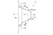
一対のウイング部2,2それぞれは、図3に示すように、それぞれに設けられた粘着部23の長さLをナプキン長手方向に2等分する粘着部中心線(固定部中心線)CLを境に前方部2Fと後方部2Rに区分したとき、該後方部2Rの面積が該前方部2Fの面積よりも小さくなるようになされている。
本実施形態のナプキン1は、図1に示すように、ウイング部2や粘着部23の位置や形状を含めて、吸収性本体11の長手方向に延びる長手方向中央線L1に対して左右対称の形状を有している。従って、以下においては、一方のウイング部のみを示す図3を参照して説明する場合もあるが、他方のウイング部についても同様である。
Adhesive is applied to one side of each of the pair of
As shown in FIG. 3, each of the pair of
As shown in FIG. 1, the
本発明者らは、着用中に生じるウイング部のめくれについて鋭意研究した結果、ウイング部のめくれがウイング部の後方側から進行しやすいことを知見し、更にウイング部の形状を、粘着部中心線CLを境に後方部2Rと前方部2Fとに区分したときの、後方部2Rの面積が前方部2Fの面積より小さくなるような形状とすることで、ウイング部のめくれを効果的に防止し得ることを知見した。
本実施形態のナプキン1においては、ウイング部2の後方部2Rの面積が前方部2Fの面積より小さくなっており、そのため、ウイング部のめくれを効果的に防止することができ、位置ズレ防止性に優れ、さらに、ウイング部のめくれが起こり難いことからウイング部による下着防汚性にも優れている。
As a result of earnest research on turning of the wing part that occurs during wearing, the present inventors have found that the turning of the wing part easily proceeds from the rear side of the wing part, and further, the shape of the wing part is determined by the center line of the adhesive part. By making the shape of the
In the
ウイング部のめくれ防止、下着股下部の側縁を充分な長さに亘って被覆し優れた下着防汚性を得る観点から、後方部2Rの面積の、前方部2Fの面積に対する割合(百分率)は50〜95%であることが好ましく、より好ましくは60〜75%である。
The ratio of the area of the
ナプキン1におけるウイング部2は、ナプキンの長手方向において相対向する前後一対の縁部25,26並びにナプキンの幅方向(ウイング部の延出方向に同じ)において相対向するウイング部先端の縁部27及びウイング部の基端28を有している。
ナプキン長手方向後側の縁部26は、図3に示すように、ウイング部先端の縁部27の後端27rとウイング部基端28の後端28rとを通る仮想直線L2より前方に位置するように湾曲している。縁部26と仮想直線L2とは交差していない。
ウイング部2の後側の縁部26が、このように湾曲していることで、ウイング部のめくれ防止性、下着の湾曲形状への適合性向上による防汚性、及びウイング部の折り返し操作性が一層良好となる。
The
As shown in FIG. 3, the
Since the
また、仮想直線L2から縁部26までの直線距離L3(図3参照)は、基端28から先端の縁部27に向かうに連れて漸次増大した後、漸次減少しており、先端の縁部27と基端28の略中間地点で最大となっている。前記距離L3の最大値は、27rと28rとを結ぶ線分の長さの5〜50%、特に5〜25%であることが好ましい。
Further, the straight line distance L3 (see FIG. 3) from the virtual straight line L2 to the
ナプキン1におけるウイング部2は、ナプキン長手方向後側の縁部26の、吸収性本体11の長手方向に対する傾斜角度θ1(図3参照)が、ナプキン長手方向前側の縁部25の、該吸収性本体11の長手方向に対する傾斜角度θ2(図3参照)と略同じである。吸収性本体の長手方向に対する傾斜角度は、吸収性本体11の長手方向中央線L1又はそれと平行な直線L1’に対する傾斜角度である。
後側の縁部26の傾斜角度θ1が、前側の縁部25の傾斜角度θ2と略同じか又は該傾斜角度θ2より小さい場合であっても、該後側の縁部26を、上述したように、仮想直線L2より前方に位置するように湾曲させることにより、基端28の長さを長めにして優れた下着防汚性を確保しながら、後方部2Rの面積を前方部2Fの面積より容易に小さくすることができる。
In the
Even when the inclination angle θ1 of the
前記傾斜角度θ1を、前記傾斜角度θ2と略同じ又はそれ以下とする場合、該傾斜角度θ1は30〜75度、特に45〜65度が好ましく、該傾斜角度θ2は50〜80度、特に60〜80度が好ましい。傾斜角度θ1と傾斜角度θ2とが略同じという場合には、両者の差の絶対値が5度以下の場合が含まれる。 When the tilt angle θ1 is substantially equal to or less than the tilt angle θ2, the tilt angle θ1 is preferably 30 to 75 degrees, particularly 45 to 65 degrees, and the tilt angle θ2 is 50 to 80 degrees, particularly 60. -80 degrees is preferable. When the inclination angle θ1 and the inclination angle θ2 are substantially the same, the case where the absolute value of the difference between the two is 5 degrees or less is included.
本実施形態のナプキン1においては、ウイング部2のナプキン長手方向前側の縁部25は、図3に示すように、直線状をなしており、ウイング部先端の縁部27の前端27fとウイング部基端28の前端28fとを通る仮想直線L4(図5参照)と重なっている。これに代えて、前側の縁部25も、図5に示す実施形態のウイング部2の前側の縁部25と同様に、該仮想直線L4より後方に位置するように湾曲させることもできる。
In the
また、ナプキン1におけるウイング部2は、先端の縁部27の長さL7が基端28の長さL8より短くなっている。先端の縁部27の長さL7が基端28の長さL8より短いことで、下着防汚性を保ちつつ、ウイングのめくれ防止性を付加することができる。縁部27の長さL7は基端28の長さL8の30〜80%、特に40〜60%であることが好ましい。
Further, in the
図4〜図7は、本発明の他の実施形態である生理用ナプキンのウイング部を示す図(図3相当図)である。図4〜図7に示す他の実施形態については、上述したナプキン1と異なる点について説明し、同様の点については同一の符号を付して説明を省略する。
4-7 is a figure (FIG. 3 equivalent view) which shows the wing part of the sanitary napkin which is other embodiment of this invention. About other embodiment shown in FIGS. 4-7, a different point from the
図4及び図5に示すウイング部2は、ナプキン長手方向後側の縁部26の、吸収性本体11の長手方向に対する傾斜角度θ1が、ナプキン長手方向前側の縁部25の、該吸収性本体11の長手方向に対する傾斜角度θ2より大きくなっている。
図4に示すウイング部2においては、前側の縁部25及び後側の縁部26は、何れも直線状をなしている。これに対して、図5に示すウイング部2においては、後側の縁部26は、ウイング部先端の縁部27の後端27rとウイング部基端28の後端28rとを通る仮想直線L2より前方に位置するように湾曲しており、前側の縁部25は、ウイング部先端の縁部27の前端27fとウイング部基端28の前端28fとを通る仮想直線L4より後方に位置するように湾曲している。
The
In the
図5に示すウイング部2のように、ウイング部2の前側及び/又は後側の縁部25,26が、非直線状の場合、非直線状の縁部の、吸収性本体11の長手方向に対する傾斜角度θ1又はθ2は、吸収性本体11の長手方向中央線L1又はそれと平行な直線L1’に対する、前記仮想直線L2,L4の角度とする。
When the front and / or
図4や図5に示すウイング部のように、後側の縁部26の傾斜角度θ1を前側の縁部25の傾斜角度θ2より大きくして、ウイング部2の後方部2Rの面積をウイング部2の前方部2Fの面積より小さくすることで、ウイング部のめくれを効果的に防止することができ、位置ズレ防止性に優れ、さらに、ウイング部のめくれが起こり難いことからウイング部による下着防汚性にも優れている。
尚、後側の縁部26の傾斜角度θ1を前側の縁部25の傾斜角度θ2より大きくする場合、前記傾斜角度θ1は50〜90度、特に60〜90度が好ましく、前記傾斜角度θ2は45〜80度、特に45〜70度が好ましく、傾斜角度の差(θ1―θ2)は、10〜30度、特に15〜25度が好ましい。
Like the wing portion shown in FIGS. 4 and 5, the inclination angle θ1 of the
When the inclination angle θ1 of the
ナプキン1におけるウイング部2の基端28は、吸収性本体11とウイング部2との境界部である。図6に示すナプキンのように、ウイング部2より前方に位置する吸収性本体の側縁部11aとウイング部2の前側の縁部25とが角部を介さずに曲線で連続している場合、又はウイング部2より後方に位置する吸収性本体の側縁部11bとウイング部2の後側の縁部26とが角部を介さずに曲線で連続している場合、図6に示すように、吸収性本体11の長手方向中央線L1又はそれと平行な直線L1’に対する、ナプキン周縁部の接線の角度θ3が30度となる該周縁部上の点を、ウイング部2の基部28の前端28f又は後端28rとする。
また、図6に示すナプキンのように、ウイング部2の前側の縁部25とウイング部先端の縁部27とが角部を介さずに曲線で連続している場合、又はウイング部2の後側の縁部26とウイング部先端の縁部27とが角部を介さずに曲線で連続している場合、図6に示すように、吸収性本体11の長手方向中央線L1又はそれと平行な直線L1’に対する、ナプキン周縁部の接線の角度θ4が45度となる該周縁部上の点を、ウイング部2の先端の縁部27の前端27f又は後端27rとする。
A
In addition, as in the case of the napkin shown in FIG. 6, when the
図7に示すウイング部2においては、ウイング部2の先端の縁部27が、吸収性本体11の長手方向に対して傾斜している。ウイング部先端の縁部27の傾斜方向は、該縁部27の後端27rより前端27fの方が吸収性本体11の長手方向中央線L1の近くに位置する向きであっても良いが、図7に示すように、該縁部27の前端27fより後端27rの方が吸収性本体11の長手方向中央線L1の近くに位置する向きに傾斜していることが好ましい。後者の向き(図7に示す向き)に傾斜している場合、収性本体11の長手方向中央線L1又はそれと平行な直線L1’に対する、該縁部27の傾斜角度θ5は、10〜45、特に15〜30であることが好ましい。
In the
上述したナプキン1の各部の形成材料としては、この種の吸収性物品に従来用いられている各種の材料を特に制限なく用いることができる。例えば表面シート13としては親水性の不織布や開孔フィルムなどを用いることができる。裏面シート16としては、液不透過性の樹脂フィルムや、樹脂フィルムと不織布、織布との積層体などを用いることができる。吸収体14としては、フラッフパルプの積繊体又はフラッフパルプと高吸収性ポリマーの粒子との混合積繊体をティッシュペーパー等の透水性材料で被覆したもの等を用いることができる。粘着部23は、ウイング部を形成するシート材に、スチレン−ブタジエン、スチレン−イソプレン系のような各種ホットメルト型粘着剤等を塗工したり、各種粘着テープを貼着したりして形成することができる。また、本発明の固定部としては、粘着部の他、機械的面ファスナー(マジックテープ(登録商標)等)のオス材等を用いることもできる。
また、ウイング部形成用シート22としては、伸縮性のシートを用いることもできるが、実質的に非伸縮性のシートを用いることもできる。ウイング部形成用シート22としては、各種製法による不織布、不織布と樹脂フィルムとの積層体、不織布と紙、織物等との積層体等を用いることができる。尚、本発明においては、ウイング部にシートを蛇腹状の折り曲げてなる拡縮部等を形成する必要もない。
As a material for forming each part of the
In addition, as the wing portion forming sheet 22, a stretchable sheet can be used, but a substantially non-stretchable sheet can also be used. As the wing portion forming sheet 22, a nonwoven fabric by various manufacturing methods, a laminate of a nonwoven fabric and a resin film, a laminate of a nonwoven fabric and paper, a fabric, or the like can be used. In the present invention, it is not necessary to form an expansion / contraction portion or the like formed by bending the sheet in a bellows shape in the wing portion.
以上、本発明のいくつかの実施形態について説明したが、本発明は上記の実施形態に制限されず、種々の変更可能である。
例えば、図8に示す生理用ナプキンのように、吸収性本体11の肌対向面を、液透過性の表面シート13及びその両側それぞれに一部を重ねるように連設した一対のサイド防漏シート15から構成し、ウイング部2を、吸収体14の両側縁から外方に延出した、サイド防漏シート15及び裏面シート16から構成することもできる。また、表面シート13、裏面シート16及びサイド防漏シート15の何れか一つ又は2以上を、吸収体14の両側縁から外方に延出させ、延出させた一枚のシート又は二枚以上のシートの積層体によりウイング部2を形成することもできる。
As mentioned above, although several embodiment of this invention was described, this invention is not restrict | limited to said embodiment, A various change is possible.
For example, like the sanitary napkin shown in FIG. 8, a pair of side leakage prevention sheets in which the skin facing surface of the absorbent
また、上述したナプキン1における粘着部23は、平面視して長方形状であったが、粘着部等の固定部の平面視形状は、正方形状であっても良く、ウイング部の固定性からは、幅方向端部のウイングの外観形状に類似した形態が良く、例えば、図3〜図6に示す形状のウイング部では、長方形や台形のようにウイング先端部と平行に固定部の幅方向側部の形状が形成されていることが好ましく、図7に示す形状のウイング部では、三角形や五角形のようなウイング先端の突起に合致した形状が良い。
固定部の長手方向長さは、長手方向中央線に対して、最も前方に位置する部分と最も後方に位置する部分との間の長さとし、その長さを吸収性物品長手方向に2等分する粘着部中心線を境に前方部と後方部に区分する。
なお、粘着剤が塗工される際に発生する意図しない塗工ムラ(塗工範囲を越えて粘着剤がある部分)は、下着に対する接着力が低いことから粘着部(固定部)から除くことが好ましい。
また、上述した各実施形態においては、粘着部に代えて、機械的面ファスナーのオス材等からなる機械的係合部を固定部として設けることもできる。
Moreover, although the
The length in the longitudinal direction of the fixed portion is the length between the frontmost portion and the rearmost portion with respect to the longitudinal center line, and the length is divided into two in the longitudinal direction of the absorbent article. It is divided into a front part and a rear part on the boundary of the adhesive part center line.
In addition, unintentional coating unevenness (parts where the adhesive is present beyond the coating range) that occurs when the adhesive is applied should be removed from the adhesive part (fixed part) due to its low adhesive strength to underwear. Is preferred.
Moreover, in each embodiment mentioned above, it can replace with the adhesion part and can provide the mechanical engaging part which consists of a male material etc. of a mechanical hook-and-loop fastener as a fixing | fixed part.
また、本発明の吸収性物品は、生理用ナプキンの他、パンティライナー(おりものシート)、失禁パッド等であっても良い。
また、上述した一の実施形態における説明省略部分及び一の実施形態のみが有する要件は、それぞれ他の実施形態に適宜適用することができ、また、各実施形態における要件は、適宜、実施形態間で相互に置換可能である。
In addition to the sanitary napkin, the absorbent article of the present invention may be a panty liner (origami sheet), an incontinence pad, or the like.
In addition, the description omitted in one embodiment and the requirements of only one embodiment can be applied to other embodiments as appropriate, and the requirements in each embodiment can be appropriately applied between the embodiments. Can be substituted for each other.
1 生理用ナプキン(吸収性物品)
11 吸収性本体
12 吸収層
13 表面シート
14 吸収体
15 サイド防漏シート
16 裏面シート(防漏層)
2 ウイング部
2F 前方部
2R 後方部
23 粘着部(固定部)
CL 粘着部中心線(固定部中心線)
25 ウイング部の吸収性物品長手方向前側の縁部
26 ウイング部の吸収性物品長手方向後側の縁部
27 ウイング部の先端の縁部
27r 先端の縁部の後端
28 ウイング部の基端
28r 基端の後端
1 Sanitary napkin (absorbent article)
DESCRIPTION OF
2
CL adhesive center line (fixed part center line)
25 Edge of absorbent article longitudinal direction front side of
Claims (5)
前記吸収性物品は、生理用ナプキンであり、
一対のウイング部それぞれは、吸収性物品の長手方向において相対向する前後一対の縁部並びに吸収性物品の幅方向において相対向するウイング部先端の縁部及びウイング部の基端を有しており、
一対のウイング部それぞれは、前記先端の縁部の前端が前記基端の前端より後方に位置すると共に前記先端の縁部の後端が前記基端の後端より前方に位置して、前記先端の縁部の長さが前記基端の長さよりも短くなっており、
一対のウイング部それぞれは、前記固定部の長さを吸収性物品長手方向に2等分する固定部中心線を境に前方部と後方部に区分したとき、該後方部の面積が該前方部の面積よりも小さい吸収性物品。 An absorbent main body having an absorbent layer and a leak-proof layer, and provided on both sides of the absorbent main body in the longitudinal direction, and in use, is bent to the non-skin facing surface side of the underwear and the non-skin facing of the underwear through a fixing portion In an absorbent article having a pair of wing parts fixed to the surface,
The absorbent article is a sanitary napkin,
Each of the pair of wing portions has a pair of front and rear edge portions opposed to each other in the longitudinal direction of the absorbent article, an edge portion of the wing portion distal end opposed to each other in the width direction of the absorbent article, and a proximal end of the wing portion. ,
Each of the pair of wing portions includes a front end of the edge of the distal end positioned behind the front end of the proximal end, and a rear end of the edge of the distal end positioned forward of the rear end of the proximal end. The length of the edge of the base is shorter than the length of the proximal end,
Each of the pair of wing parts is divided into a front part and a rear part with a fixed part center line that bisects the length of the fixed part in the longitudinal direction of the absorbent article as a boundary. Absorbent article smaller than the area of.
Priority Applications (1)
| Application Number | Priority Date | Filing Date | Title |
|---|---|---|---|
| JP2006186635A JP4986519B2 (en) | 2006-07-06 | 2006-07-06 | Absorbent articles |
Applications Claiming Priority (1)
| Application Number | Priority Date | Filing Date | Title |
|---|---|---|---|
| JP2006186635A JP4986519B2 (en) | 2006-07-06 | 2006-07-06 | Absorbent articles |
Publications (2)
| Publication Number | Publication Date |
|---|---|
| JP2008012097A JP2008012097A (en) | 2008-01-24 |
| JP4986519B2 true JP4986519B2 (en) | 2012-07-25 |
Family
ID=39069724
Family Applications (1)
| Application Number | Title | Priority Date | Filing Date |
|---|---|---|---|
| JP2006186635A Active JP4986519B2 (en) | 2006-07-06 | 2006-07-06 | Absorbent articles |
Country Status (1)
| Country | Link |
|---|---|
| JP (1) | JP4986519B2 (en) |
Families Citing this family (2)
| Publication number | Priority date | Publication date | Assignee | Title |
|---|---|---|---|---|
| EP2338453A1 (en) * | 2009-12-23 | 2011-06-29 | 3M Innovative Properties Company | Hygiene Article |
| JP2016104089A (en) * | 2014-12-01 | 2016-06-09 | ユニ・チャーム株式会社 | Absorbent article |
Family Cites Families (9)
| Publication number | Priority date | Publication date | Assignee | Title |
|---|---|---|---|---|
| JPS6290624U (en) * | 1985-11-27 | 1987-06-10 | ||
| JP3419476B2 (en) * | 1992-07-30 | 2003-06-23 | サイティック株式会社 | Absorbent products |
| CA2127759A1 (en) * | 1994-04-20 | 1995-10-21 | Thomas Peter Van Iten | Panty shield |
| JP2974970B2 (en) * | 1996-08-02 | 1999-11-10 | ザ、プロクター、エンド、ギャンブル、カンパニー | Absorbent articles |
| EP1208823A1 (en) * | 2000-11-25 | 2002-05-29 | The Procter & Gamble Company | Absorbent articles with asymmetric flaps |
| JP4094279B2 (en) * | 2001-11-21 | 2008-06-04 | 大王製紙株式会社 | Absorbent articles |
| US20040087425A1 (en) * | 2002-10-31 | 2004-05-06 | Ng Tony C. | Process for applying portions of material to a moving web |
| JP4190329B2 (en) * | 2003-03-28 | 2008-12-03 | 大王製紙株式会社 | Sanitary napkin |
| US20050283131A1 (en) * | 2004-06-18 | 2005-12-22 | Kimberly-Clark Worldwide, Inc. | Absorbent article having wings with non-bunching/twisting security |
-
2006
- 2006-07-06 JP JP2006186635A patent/JP4986519B2/en active Active
Also Published As
| Publication number | Publication date |
|---|---|
| JP2008012097A (en) | 2008-01-24 |
Similar Documents
| Publication | Publication Date | Title |
|---|---|---|
| JP2008136739A (en) | Absorbent article | |
| JP6005027B2 (en) | Absorbent articles | |
| JP6442274B2 (en) | Absorbent articles | |
| JP5558617B1 (en) | Absorbent pad | |
| JP2015100502A5 (en) | ||
| JP5558616B2 (en) | Absorbent pad | |
| JP4641979B2 (en) | Absorbent articles | |
| JP6115949B2 (en) | Absorbent articles | |
| JP5685421B2 (en) | Absorbent articles | |
| JP5978349B1 (en) | Absorbent articles | |
| JP4986519B2 (en) | Absorbent articles | |
| JP6161202B2 (en) | Absorbent articles | |
| JP6373092B2 (en) | Absorbent articles | |
| JP5188597B2 (en) | Absorbent articles | |
| JP5671296B2 (en) | Absorbent articles | |
| JP5053806B2 (en) | Sanitary napkin | |
| JP4859905B2 (en) | Absorbent articles | |
| JP3744925B2 (en) | Disposable urine pad | |
| JP7152256B2 (en) | absorbent article | |
| WO2014084087A1 (en) | Absorptive pad | |
| JP3818923B2 (en) | Absorbent articles | |
| JP5978350B1 (en) | Absorbent articles | |
| JP4801421B2 (en) | Disposable diapers | |
| JP7217130B2 (en) | absorbent article | |
| JP2009268687A (en) | Absorbent article |
Legal Events
| Date | Code | Title | Description |
|---|---|---|---|
| A621 | Written request for application examination |
Free format text: JAPANESE INTERMEDIATE CODE: A621 Effective date: 20090525 |
|
| A977 | Report on retrieval |
Free format text: JAPANESE INTERMEDIATE CODE: A971007 Effective date: 20110201 |
|
| A131 | Notification of reasons for refusal |
Free format text: JAPANESE INTERMEDIATE CODE: A131 Effective date: 20110823 |
|
| A521 | Request for written amendment filed |
Free format text: JAPANESE INTERMEDIATE CODE: A523 Effective date: 20111018 |
|
| TRDD | Decision of grant or rejection written | ||
| A01 | Written decision to grant a patent or to grant a registration (utility model) |
Free format text: JAPANESE INTERMEDIATE CODE: A01 Effective date: 20120424 |
|
| A01 | Written decision to grant a patent or to grant a registration (utility model) |
Free format text: JAPANESE INTERMEDIATE CODE: A01 |
|
| A61 | First payment of annual fees (during grant procedure) |
Free format text: JAPANESE INTERMEDIATE CODE: A61 Effective date: 20120424 |
|
| R151 | Written notification of patent or utility model registration |
Ref document number: 4986519 Country of ref document: JP Free format text: JAPANESE INTERMEDIATE CODE: R151 |
|
| FPAY | Renewal fee payment (event date is renewal date of database) |
Free format text: PAYMENT UNTIL: 20150511 Year of fee payment: 3 |
|
| R250 | Receipt of annual fees |
Free format text: JAPANESE INTERMEDIATE CODE: R250 |
|
| R250 | Receipt of annual fees |
Free format text: JAPANESE INTERMEDIATE CODE: R250 |
|
| R250 | Receipt of annual fees |
Free format text: JAPANESE INTERMEDIATE CODE: R250 |
|
| R250 | Receipt of annual fees |
Free format text: JAPANESE INTERMEDIATE CODE: R250 |
|
| R250 | Receipt of annual fees |
Free format text: JAPANESE INTERMEDIATE CODE: R250 |
|
| R250 | Receipt of annual fees |
Free format text: JAPANESE INTERMEDIATE CODE: R250 |
|
| R250 | Receipt of annual fees |
Free format text: JAPANESE INTERMEDIATE CODE: R250 |
|
| R250 | Receipt of annual fees |
Free format text: JAPANESE INTERMEDIATE CODE: R250 |
|
| R250 | Receipt of annual fees |
Free format text: JAPANESE INTERMEDIATE CODE: R250 |