JP4972467B2 - Low purity nitrogen gas generation method - Google Patents
Low purity nitrogen gas generation method Download PDFInfo
- Publication number
- JP4972467B2 JP4972467B2 JP2007149997A JP2007149997A JP4972467B2 JP 4972467 B2 JP4972467 B2 JP 4972467B2 JP 2007149997 A JP2007149997 A JP 2007149997A JP 2007149997 A JP2007149997 A JP 2007149997A JP 4972467 B2 JP4972467 B2 JP 4972467B2
- Authority
- JP
- Japan
- Prior art keywords
- pressure
- adsorption
- nitrogen gas
- product
- nitrogen
- Prior art date
- Legal status (The legal status is an assumption and is not a legal conclusion. Google has not performed a legal analysis and makes no representation as to the accuracy of the status listed.)
- Active
Links
- IJGRMHOSHXDMSA-UHFFFAOYSA-N Atomic nitrogen Chemical compound N#N IJGRMHOSHXDMSA-UHFFFAOYSA-N 0.000 title claims description 146
- 238000000034 method Methods 0.000 title claims description 67
- 229910001873 dinitrogen Inorganic materials 0.000 title claims description 54
- 238000001179 sorption measurement Methods 0.000 claims description 107
- QVGXLLKOCUKJST-UHFFFAOYSA-N atomic oxygen Chemical compound [O] QVGXLLKOCUKJST-UHFFFAOYSA-N 0.000 claims description 60
- 239000001301 oxygen Substances 0.000 claims description 60
- 229910052760 oxygen Inorganic materials 0.000 claims description 60
- 229910052757 nitrogen Inorganic materials 0.000 claims description 46
- 239000003463 adsorbent Substances 0.000 claims description 38
- 239000002994 raw material Substances 0.000 claims description 24
- 238000000926 separation method Methods 0.000 claims description 16
- 230000008929 regeneration Effects 0.000 claims description 14
- 238000011069 regeneration method Methods 0.000 claims description 14
- OKTJSMMVPCPJKN-UHFFFAOYSA-N Carbon Chemical compound [C] OKTJSMMVPCPJKN-UHFFFAOYSA-N 0.000 claims description 12
- 229910052799 carbon Inorganic materials 0.000 claims description 12
- 239000002808 molecular sieve Substances 0.000 claims description 12
- URGAHOPLAPQHLN-UHFFFAOYSA-N sodium aluminosilicate Chemical compound [Na+].[Al+3].[O-][Si]([O-])=O.[O-][Si]([O-])=O URGAHOPLAPQHLN-UHFFFAOYSA-N 0.000 claims description 12
- 230000006837 decompression Effects 0.000 claims description 3
- 239000007789 gas Substances 0.000 description 35
- 238000010926 purge Methods 0.000 description 17
- 239000003795 chemical substances by application Substances 0.000 description 9
- 230000007423 decrease Effects 0.000 description 6
- 238000002474 experimental method Methods 0.000 description 5
- 238000005259 measurement Methods 0.000 description 4
- 238000010586 diagram Methods 0.000 description 3
- 238000000605 extraction Methods 0.000 description 3
- CURLTUGMZLYLDI-UHFFFAOYSA-N Carbon dioxide Chemical compound O=C=O CURLTUGMZLYLDI-UHFFFAOYSA-N 0.000 description 2
- 238000012423 maintenance Methods 0.000 description 2
- 229910000831 Steel Inorganic materials 0.000 description 1
- 230000033228 biological regulation Effects 0.000 description 1
- 229910002092 carbon dioxide Inorganic materials 0.000 description 1
- 239000001569 carbon dioxide Substances 0.000 description 1
- 238000002485 combustion reaction Methods 0.000 description 1
- 230000003247 decreasing effect Effects 0.000 description 1
- 230000000694 effects Effects 0.000 description 1
- 239000000295 fuel oil Substances 0.000 description 1
- 239000011261 inert gas Substances 0.000 description 1
- 239000000344 soap Substances 0.000 description 1
- 239000004071 soot Substances 0.000 description 1
- 239000010959 steel Substances 0.000 description 1
- 239000000126 substance Substances 0.000 description 1
- 230000009897 systematic effect Effects 0.000 description 1
- 230000036962 time dependent Effects 0.000 description 1
- 238000010792 warming Methods 0.000 description 1
Images


Classifications
-
- B—PERFORMING OPERATIONS; TRANSPORTING
- B01—PHYSICAL OR CHEMICAL PROCESSES OR APPARATUS IN GENERAL
- B01D—SEPARATION
- B01D53/00—Separation of gases or vapours; Recovering vapours of volatile solvents from gases; Chemical or biological purification of waste gases, e.g. engine exhaust gases, smoke, fumes, flue gases, aerosols
- B01D53/02—Separation of gases or vapours; Recovering vapours of volatile solvents from gases; Chemical or biological purification of waste gases, e.g. engine exhaust gases, smoke, fumes, flue gases, aerosols by adsorption, e.g. preparative gas chromatography
- B01D53/04—Separation of gases or vapours; Recovering vapours of volatile solvents from gases; Chemical or biological purification of waste gases, e.g. engine exhaust gases, smoke, fumes, flue gases, aerosols by adsorption, e.g. preparative gas chromatography with stationary adsorbents
- B01D53/047—Pressure swing adsorption
-
- C—CHEMISTRY; METALLURGY
- C01—INORGANIC CHEMISTRY
- C01B—NON-METALLIC ELEMENTS; COMPOUNDS THEREOF; METALLOIDS OR COMPOUNDS THEREOF NOT COVERED BY SUBCLASS C01C
- C01B21/00—Nitrogen; Compounds thereof
- C01B21/04—Purification or separation of nitrogen
- C01B21/0405—Purification or separation processes
- C01B21/0433—Physical processing only
- C01B21/045—Physical processing only by adsorption in solids
- C01B21/0455—Physical processing only by adsorption in solids characterised by the adsorbent
- C01B21/0461—Carbon based materials
Description
本発明は、低純度窒素ガス発生方法に関し、詳しくは、分子ふるい炭素を吸着剤とした圧力変動吸着法によって空気中の窒素と酸素とを分離する窒素ガス発生装置を使用して酸素含有率が3〜5体積%の低純度窒素ガスを発生させる方法に関する。 The present invention relates to a low-purity nitrogen gas generation method, and in particular, the oxygen content rate is determined by using a nitrogen gas generator that separates nitrogen and oxygen in the air by a pressure fluctuation adsorption method using molecular sieve carbon as an adsorbent. The present invention relates to a method of generating 3 to 5% by volume of low purity nitrogen gas.
分子ふるい炭素を吸着剤とした圧力変動吸着法(PSA法)により、空気から窒素ガス(以下、窒素に富むガスも含めて単に窒素と呼ぶことがある。)を分離発生する方法が知られている。この分子ふるい炭素を使用するPSA法は、典型的には、分子ふるい炭素をそれぞれ充填した2筒の吸着筒に対して、適当な圧力に加圧した原料空気を導入して筒内を所定の圧力にする加圧工程、吸着しやすい酸素分を吸着剤に優先的に吸着させて吸着しにくい窒素ガスを採取して製品タンクに送り出す吸着工程(製品取出工程)、筒内に残留する窒素分を他の吸着筒に送り出す減圧均圧工程、吸着筒を大気に解放して圧力を下げることにより吸着剤に吸着していた酸素分を脱着させて吸着剤を再生する再生工程、他の吸着筒内から窒素分を受け入れる加圧均圧工程の各工程を2筒の吸着筒で交互に繰り返して行うことにより空気中の窒素を分離する。 There is known a method for separating and generating nitrogen gas (hereinafter also referred to simply as nitrogen, including nitrogen-rich gas) from air by pressure fluctuation adsorption method (PSA method) using molecular sieve carbon as an adsorbent. Yes. In the PSA method using molecular sieve carbon, typically, raw air pressurized to an appropriate pressure is introduced into two cylinders filled with molecular sieve carbon, and a predetermined amount of gas is introduced into the cylinder. Pressurizing process to make pressure, adsorbing preferentially adsorbed oxygen content to adsorbent, collecting nitrogen gas that is hard to adsorb and feeding it to the product tank (product extracting process), nitrogen content remaining in the cylinder Pressure reduction and pressure equalization process to send the adsorbent to the other adsorbing cylinder, the adsorbing cylinder is released to the atmosphere and the pressure is lowered to desorb the oxygen adsorbed on the adsorbent and regenerate the adsorbent, other adsorbing cylinder Nitrogen in the air is separated by alternately repeating each step of the pressure equalization step for receiving nitrogen from the inside by two adsorption cylinders.
この方法は、1分前後の比較的短い運転サイクルで圧力を変化させることができるので、吸着剤単位重量当たりの空気処理量を大きくすることができる。このため、従来から行われている深冷空気分離法に対し、装置構成を大幅に簡略化でき、設備コストの面でも優位にあるため、このようなPSA法による窒素ガス発生装置(窒素PSA装置)は、小/中規模の窒素発生用として広く採用されている。 In this method, since the pressure can be changed in a relatively short operation cycle of about 1 minute, the amount of air treated per unit weight of the adsorbent can be increased. For this reason, since the apparatus configuration can be greatly simplified and the equipment cost is superior to the conventional cryogenic air separation method, a nitrogen gas generator (nitrogen PSA apparatus) based on such a PSA method can be used. ) Is widely used for small / medium nitrogen generation.
例えば、2筒の吸着筒(A,B)を使用した窒素PSA装置において、前記各均圧工程(減圧均圧工程及び加圧均圧工程)とは、A筒とB筒との間のバルブを開き、圧力が高い吸着筒の圧力を圧力が低い吸着筒に回収することを目的とし、両筒の圧力を略均等にする工程である。この間、原料空気は吸着筒に導入されず、また、吸着筒から製品タンクに製品ガスは流れない。すなわち、各均圧工程中は、製品タンクの残圧分で製品ガスを供給することになる。さらに、均圧工程が終了して加圧工程に移行した際、製品タンクの圧力よりも吸着筒の圧力が高くなるまでは製品タンクに製品ガスは供給されない。 For example, in a nitrogen PSA apparatus using two adsorption cylinders (A, B), each of the pressure equalization steps (the pressure reduction pressure equalization step and the pressure equalization step) is a valve between the A cylinder and the B cylinder. Is a step of making the pressures of both cylinders substantially equal, with the purpose of collecting the pressure of the suction cylinders with high pressure in the suction cylinders with low pressure. During this time, raw material air is not introduced into the adsorption cylinder, and product gas does not flow from the adsorption cylinder to the product tank. That is, during each pressure equalization process, the product gas is supplied with the residual pressure in the product tank. Furthermore, when the pressure equalization process is completed and the process proceeds to the pressurization process, the product gas is not supplied to the product tank until the pressure in the adsorption cylinder becomes higher than the pressure in the product tank.
一般に、高純度窒素ガスを発生させる場合、製品ガス供給量が少ないために製品タンクの圧力の低下は小さい。しかしながら、低純度窒素ガスを発生させる場合、製品ガス供給量が多いために製品タンク圧力の低下はおおきくなる。このため、前記均圧工程の時間が長くなると、客先が要求する保証圧力を維持できなくなるおそれがある。この場合、製品タンクを大きくすることで保証圧力以上を維持することはできるが、コストアップを招いたり、装置が大きくなるため、均圧時間の長い運転方法は適用できない。また、製品タンクの圧力変動幅(最大圧力と最小圧力の幅)が大きくなると純度は低下する傾向がある。 In general, when high-purity nitrogen gas is generated, the decrease in the pressure in the product tank is small because the amount of product gas supplied is small. However, when low purity nitrogen gas is generated, the product tank pressure is greatly reduced due to the large amount of product gas supplied. For this reason, when the time of the said pressure equalization process becomes long, there exists a possibility that the guarantee pressure which a customer requires cannot be maintained. In this case, it is possible to maintain the pressure above the guaranteed pressure by enlarging the product tank. However, an operation method with a long pressure equalization time is not applicable because the cost is increased or the apparatus becomes large. In addition, the purity tends to decrease as the pressure fluctuation width (maximum pressure and minimum pressure width) of the product tank increases.
例えば、酸素含有率が3体積%未満の高純度窒素ガスを発生する窒素PSA装置では、吸着筒内の圧力上昇速度を0.15〜1.6MPa/secとし、均圧時間を7〜27秒とすることが開示されている(例えば、特許文献1参照。)。 For example, in a nitrogen PSA apparatus that generates high-purity nitrogen gas with an oxygen content of less than 3% by volume, the pressure rise rate in the adsorption cylinder is 0.15 to 1.6 MPa / sec, and the pressure equalization time is 7 to 27 seconds. (For example, refer to Patent Document 1).
一方、不活性である窒素ガスは、LPGタンカーやケミカルタンカーといった船舶に防爆用のパージガス、シールドガスとして用いられている。従来は、パージガス、シールドガスとなる窒素ガス等の不活性ガスを発生させる装置として、重油の燃焼排ガスを利用するIGG式が主流であったが、地球温暖化ガスである二酸化炭素を大量に含むことや、汚れ(スス)を含むことから頻繁にメンテナンスが必要であり、クリーンでメンテナンス回数が少ないPSA法による窒素PSA装置が注目され始め、窒素PSA装置を搭載することが多くなってきている。
船舶における防爆用のパージガスやシールガスとして使用する際の窒素ガスは、鋼船規則により、窒素ガス中の酸素濃度が5体積%まで含んだ比較的低純度の窒素ガスでよく、一般の工業的に使用される窒素ガスとは異なり、必ずしも高純度の窒素ガスを必要としない。しかし、窒素PSA装置を船舶に収めなければならないため、装置の大きさ、特に高さに制限があり、コンパクトな装置で、所定の純度、圧力の窒素ガスを効率的に発生させることが要求される。 Nitrogen gas for use as an explosion-proof purge gas or seal gas in ships may be a relatively low-purity nitrogen gas containing up to 5% by volume of oxygen in the nitrogen gas in accordance with steel ship regulations. Unlike the nitrogen gas used in the above, high-purity nitrogen gas is not necessarily required. However, since the nitrogen PSA device must be housed in a ship, the size of the device, particularly the height, is limited, and it is required to efficiently generate nitrogen gas of a predetermined purity and pressure with a compact device. The
そこで本発明は、船舶における防爆用のパージガスやシールガスとして使用する酸素含有率が3〜5体積%の低純度窒素ガスを効率よく発生させることができ、窒素PSA装置の小型化を図ることができる窒素ガス発生方法を提供することを目的としている。 Therefore, the present invention can efficiently generate low-purity nitrogen gas having an oxygen content of 3 to 5% by volume used as an explosion-proof purge gas or seal gas in a ship, and can reduce the size of a nitrogen PSA device. An object of the present invention is to provide a method for generating nitrogen gas.
上記目的を達成するため、本発明の窒素ガス発生方法は、吸着剤として分子ふるい炭素を充填した吸着筒に対して加圧、製品取出、減圧均圧、再生、加圧均圧の各工程を繰り返す圧力変動吸着法によって空気から酸素含有率が3〜5体積%の低純度窒素ガスを発生させる方法において、導入する原料空気の圧力をゲージ圧で0.7〜1.0MPaの範囲に設定し、かつ、前記加圧工程及び製品取出工程での吸着筒内の原料空気の空間速度を1500〜2500hr−1の範囲に設定するとともに、装置からの製品窒素の取出量を220〜700Nm3/hr・tonの範囲に設定することを特徴としている。 In order to achieve the above object, the nitrogen gas generation method of the present invention includes steps of pressurization, product removal, decompression pressure equalization, regeneration, and pressure equalization for an adsorption cylinder filled with molecular sieve carbon as an adsorbent. In the method of generating low purity nitrogen gas having an oxygen content of 3 to 5% by volume from air by repeated pressure fluctuation adsorption method, the pressure of the raw material air to be introduced is set within a range of 0.7 to 1.0 MPa as a gauge pressure. And while setting the space velocity of the raw material air in the adsorption cylinder in the said pressurization process and the product extraction process in the range of 1500-2500 hr < -1 >, the extraction amount of the product nitrogen from an apparatus is 220-700 Nm < 3 > / hr. -It is characterized by setting in the range of ton.
さらに、本発明の低純度窒素ガス発生方法は、前記分子ふるい炭素は、酸素と窒素との分離比αが37.9以上であり、かつ、酸素の吸着速度定数K(O2)が8.5×10⁻²sec−1以上であることを特徴としている。 Furthermore, in the low purity nitrogen gas generation method of the present invention, the molecular sieve carbon has an oxygen / nitrogen separation ratio α of 37.9 or more and an oxygen adsorption rate constant K (O 2 ) of 8. It is characterized by being 5 × 10 −2 sec −1 or more.
本発明の窒素ガス発生方法によれば、窒素PSA法によって空気から酸素含有率が3〜5体積%の低純度窒素ガスを効率よく発生させることができ、窒素PSA装置の小型化、分子ふるい炭素使用量の低減、装置価格の低減を図ることができる。 According to the nitrogen gas generation method of the present invention, low-purity nitrogen gas having an oxygen content of 3 to 5% by volume can be efficiently generated from the air by the nitrogen PSA method. It is possible to reduce the amount used and the equipment price.
図1及び図2は、本発明の窒素ガス発生方法を適用した窒素PSA装置の一形態例を示すもので、図1は窒素PSA装置の系統図、図2は窒素PSA装置の各工程を示す説明図である。 1 and 2 show an embodiment of a nitrogen PSA apparatus to which the nitrogen gas generation method of the present invention is applied. FIG. 1 is a system diagram of the nitrogen PSA apparatus, and FIG. 2 shows each process of the nitrogen PSA apparatus. It is explanatory drawing.
窒素PSA装置は、吸着剤として分子ふるい炭素を充填した2つの吸着筒A,Bと、原料空気を圧縮する空気圧縮機11と、原料空気を貯留する空気貯槽12と、製品ガスを貯留する製品タンク13と、吸着筒A,Bの各工程の切替プログラムにて開閉する第1入口弁14a,第2入口弁14b,第1排気弁15a,第2排気弁15b,パージ弁16,上部均圧弁17,下部均圧弁18と、第1逆止弁19a,第2逆止弁19bと、原料空気の流量を所定流量に調整する第1マスフローコントローラ20と、製品ガス供給量を所定流量に調整する第2マスフローコントローラ21と、パージガスの流量を所定流量に調整する流量調整弁22と、入口側圧力調整弁23a,出口側圧力調整弁23bと、圧力計24,25,26と、酸素濃度計27とから構成されている。
The nitrogen PSA apparatus includes two adsorption cylinders A and B filled with molecular sieve carbon as an adsorbent, an air compressor 11 that compresses raw material air, an
本窒素PSA装置は、図2に示す各工程を繰り返すことによって空気中の窒素を分離し、製品窒素ガスを採取する。なお、図2は概略図であり、各工程において開弁状態でガスが流れている経路のみを図示している。以下、工程順に各工程をそれぞれ説明する。 The nitrogen PSA apparatus separates nitrogen in the air by repeating the steps shown in FIG. 2, and collects product nitrogen gas. Note that FIG. 2 is a schematic diagram, and only shows a path through which gas flows in the valve-open state in each step. Hereinafter, each process is demonstrated in order of a process.
図2(A)は、吸着筒Aが加圧工程、吸着筒Bが再生工程の前半を行っている状態であり、吸着筒Aの第1入口弁14aが開き、吸着筒A内に所定圧力の原料空気が導入されて筒内が加圧されている状態である。このときパージ弁16と吸着筒Bの第2排気弁15bとが開となり、吸着筒Aの出口から導出した窒素ガスが流量調整弁22で流量調整され、パージ弁16を通って吸着筒Bの出口に送られ、吸着筒B内のガスが入口から放出されるとともに筒内のパージが行われる。
FIG. 2A shows a state in which the adsorption cylinder A is performing the pressurizing process and the adsorption cylinder B is performing the first half of the regeneration process, and the
図2(B)は、吸着筒Aが吸着(製品取出)工程、吸着筒Bが再生工程の後半を行っている状態であり、吸着筒Aの圧力が製品タンク13の圧力以上に上昇することにより、吸着筒Aの出口ガスが第1逆止弁19aを通過して製品タンク13に流入する。吸着筒Aの出口ガスは、筒内に充填された吸着剤(分子ふるい炭素)によって酸素が吸着されるため、所定の酸素含有率に濃縮された窒素である。一方、吸着筒Bは、筒内ガスの放出、パージが継続して行われている。
FIG. 2B shows a state in which the adsorption cylinder A is in the adsorption (product take-out) process and the adsorption cylinder B is in the latter half of the regeneration process, and the pressure in the adsorption cylinder A rises above the pressure in the
図2(C)は、吸着筒Aが吸着工程から減圧均圧工程に切り替わり、吸着筒Bが再生工程から加圧均圧工程に切り替わった状態であり、吸着筒Aの第1入口弁14a、吸着筒Bの第2排気弁15b及びパージ弁16がそれぞれ閉じ、上部均圧弁17及び下部均圧弁18がそれぞれ開く。この均圧工程では、吸着工程が終了して筒内圧力が相対的に高い吸着筒A内の窒素に富むガスが、再生工程が終了して筒内圧力が相対的に低い吸着筒Bに回収され、結果的に吸着筒Aは減圧され、吸着筒Bは加圧されることになる。
FIG. 2C shows a state in which the adsorption cylinder A is switched from the adsorption process to the pressure-reducing and pressure equalizing process, and the adsorption cylinder B is switched from the regeneration process to the pressure-equalizing and equalizing process, and the
図2(D)は、吸着筒Aが再生工程に切り替わり、吸着筒Bが加圧工程に切り替わった状態であり、吸着筒Aの第1排気弁15aが開き、筒内ガスが大気放出されることにより、吸着剤に吸着した酸素が脱着して筒外に放出される。また、パージ弁16が開いてい吸着筒Bからのパージガス(窒素ガス)が吸着筒Aの出口に導入されて更に酸素を洗い流す。また、吸着筒Bでは第2入口弁14bが開いて筒内に原料空気が導入されて加圧される。
FIG. 2 (D) shows a state in which the adsorption cylinder A is switched to the regeneration process and the adsorption cylinder B is switched to the pressurization process, the
図2(E)は、吸着筒Aが再生工程を継続し、吸着筒Bが加圧工程から吸着工程に切り替わった状態であり、吸着筒Aでは、吸着筒Bからのパージガスの導入と、第1排気弁15aからのガス放出とが継続される。また、吸着筒Bの筒内圧力が上昇したことにより、第2逆止弁19bを通して吸着筒Bから製品タンク13への製品窒素ガスの採取が行われる。
FIG. 2E shows a state in which the adsorption cylinder A continues the regeneration process, and the adsorption cylinder B is switched from the pressurization process to the adsorption process. In the adsorption cylinder A, the introduction of the purge gas from the adsorption cylinder B, 1 The gas discharge from the
図2(F)は、吸着筒Aが再生工程から加圧均圧工程に切り替わり、吸着筒Bが吸着工程から減圧均圧工程に切り替わった状態であり、吸着筒Bの第2入口弁14b、吸着筒Aの第1排気弁15a及びパージ弁16が閉じ、両均圧弁17,18が開く。この均圧工程では、吸着工程が終了した吸着筒B内の窒素に富むガスが、再生工程が終了している吸着筒Aに回収される。
FIG. 2F shows a state in which the adsorption cylinder A is switched from the regeneration process to the pressurization and pressure equalization process, and the adsorption cylinder B is switched from the adsorption process to the decompression and pressure equalization process, and the
このような加圧、製品取出、減圧均圧、再生、加圧均圧の各工程を繰り返すことにより、空気から窒素が分離されて製品窒素ガスが得られる。なお、逆支弁19a,19bに代えて開閉弁を用いたり、パージ弁16及び流量調整弁22に代えてオリフィスを用いたりすることもできる。また、吸着筒を3筒以上設けた多筒式PSA装置とすることにより、吸着筒の小型化、特に筒高さを低くするとともに、製品純度や製品タンク圧力の安定化を図ることができる。なお、再生工程では、必要に応じて真空ポンプで筒内を減圧排気するようにしてもよい。
By repeating these steps of pressurization, product removal, reduced pressure equalization, regeneration, and pressure equalization, nitrogen is separated from air and product nitrogen gas is obtained. An on-off valve may be used in place of the reversely supported
このような工程を繰り返すPSA操作では、工程の切替時間を適切に設定する必要があり、原料空気の流量と製品窒素ガスの流量とを固定したときに、切替時間が短すぎると筒内圧力が原料空気供給圧力に到達せずに吸着剤の性能を十分に発揮できなくなり、吸着時間が長すぎると原料空気導入量が多くなるために吸着剤の酸素吸着量が飽和し、酸素が破過して製品窒素ガスの純度が低下してしまう。さらに、使用する吸着剤の酸素吸着速度、窒素吸着速度によって適切な切替時間を選定することも重要である。すなわち、酸素吸着速度が速い吸着剤を使用する場合には早めの切替時間とする必要がある。したがって、製品窒素ガスの供給量、原料空気量、吸着剤の性能に応じて最適な切替時間を設定することにより、所定流量、所定純度の製品窒素ガスを効率よく発生させることが可能となる。 In the PSA operation in which such a process is repeated, it is necessary to appropriately set the process switching time. When the flow rate of the raw material air and the flow rate of the product nitrogen gas are fixed, if the switching time is too short, the in-cylinder pressure Adsorbent performance cannot be fully achieved without reaching the feed air supply pressure, and if the adsorption time is too long, the amount of feed air introduced will increase, so the adsorbent oxygen adsorption will saturate and oxygen will break through. As a result, the purity of the product nitrogen gas decreases. It is also important to select an appropriate switching time depending on the oxygen adsorption rate and nitrogen adsorption rate of the adsorbent used. That is, when an adsorbent having a high oxygen adsorption rate is used, it is necessary to set an earlier switching time. Therefore, by setting an optimal switching time according to the supply amount of the product nitrogen gas, the amount of raw material air, and the performance of the adsorbent, it is possible to efficiently generate the product nitrogen gas having a predetermined flow rate and a predetermined purity.
まず、試料として4種類の分子ふるい炭素(MSC−I,II,III,IV)を用意し、各試料における酸素及び窒素の吸着速度を測定した。吸着速度の測定は、市販の定容法測定装置(日本ベル(株)製ベルソープ28)を用いて定容積容器中での吸着による圧力の経時変化を測定することにより行った。各試料約1gを正確に計量し、真空下に30分で100℃に昇温後、これを2時間保持する前処理をそれぞれ行った後、温度約25℃、導入圧力200Torrの条件で測定を行った。 First, four types of molecular sieve carbon (MSC-I, II, III, IV) were prepared as samples, and the adsorption rates of oxygen and nitrogen in each sample were measured. The adsorption rate was measured by measuring the time-dependent change in pressure due to adsorption in a constant volume container using a commercially available constant volume method measuring device (Bell Soap 28 manufactured by Nippon Bell Co., Ltd.). About 1 g of each sample is accurately weighed, heated to 100 ° C. in 30 minutes under vacuum, and then subjected to pretreatment for 2 hours, followed by measurement at a temperature of about 25 ° C. and an introduction pressure of 200 Torr. went.
測定で得られた圧力変化データを基に、経時による圧力変化曲線を作成し、これにLDF吸着速度モデル(Linear Driving Force Model)から得られる理論圧力変化曲線が、平衡吸着量の50%の吸着量で一致するように吸着速度定数Kを決定した。表1に各試料(MSC−I,II,III,IV)のそれぞれにおける酸素の吸着速度定数K(O2)及び窒素の吸着速度定数K(N2)の測定結果とその比率(K(O2)/K(N2)、分離比α)を示す。

この測定結果で相対的に酸素の吸着速度が速いMSC−I及び酸素の吸着速度が遅いMSC−IIIの2種類の吸着剤を図1に示した構成の窒素PSA装置にそれぞれ使用して空気から窒素ガスを発生させる実験を行った。実験は、MSC−Iでは原料空気圧力を0.7MPa(ゲージ圧、以下同じ)、空間速度(SV値:時間当たり導入される空気量と吸着剤の充填量の比率)を1500hr−1、製品流量を27NL/min(標準状態換算)に、MSC−IIIでは原料空気圧力を0.70MPa(ゲージ圧、以下同様)、SV=1500hr−1、製品流量18NL/minにそれぞれ設定し、均圧工程を1秒に固定して加圧工程と吸着工程と均圧時間との合計の時間である切替時間を変化させ、各実験で得られた製品窒素ガスの純度をそれぞれ測定した。結果を表2(MSC−I)及び表3(MSC−III)にそれぞれ示す。
表2及び表3の結果から、製品窒素ガスの純度が最も良くなる切替時間は、酸素の吸着速度が速いMSC−Iでは43秒であり、酸素の吸着速度が遅いMSC−IIIでは55秒であった。したがって、使用する吸着剤の性能(吸着速度定数K(O2)、K(N2)及び分離比(α)によって最適なPSA運転条件を設定する必要があることが分かる。 From the results of Tables 2 and 3, the switching time when the purity of the product nitrogen gas is the best is 43 seconds for MSC-I, which has a high oxygen adsorption rate, and 55 seconds for MSC-III, which has a slow oxygen adsorption rate. there were. Therefore, it can be seen that it is necessary to set an optimum PSA operating condition according to the performance of the adsorbent used (adsorption rate constants K (O 2 ), K (N 2 ) and separation ratio (α).
各吸着剤MSC−I〜IVについて、単位時間当たりの原料空気導入量と吸着剤充填量との比率(SV値)の影響について実験を行った。各SV値における切替時間は、実施例1で得られた最適な切替時間から、切替時間中の空気導入時間(切替時間−均圧時間)とSV値との積が一定となるように調整した。すなわち、SV値を、SV=1000hr−1からSV=2000hr−1に変更した場合、切替時間中の空気導入時間は半分となる。 For each of the adsorbents MSC-I to IV, an experiment was performed on the influence of the ratio (SV value) between the raw material air introduction amount per unit time and the adsorbent filling amount. The switching time at each SV value was adjusted from the optimum switching time obtained in Example 1 so that the product of the air introduction time (switching time-pressure equalizing time) and the SV value during the switching time was constant. . That is, the SV value, if you change from SV = 1000 hr -1 to SV = 2000 hr -1, the air introduction time during switching time is half.
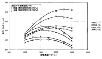
例えば、実施例1におけるMSC−Iでは、切替時間43秒とSV=1500hr−1との積を基準とし、流量を調整して製品純度が95、96、97各体積%となる条件を選定し、その条件をベースにして各吸着剤の能力を試算した。その結果を図3〜5に示す。図3は製品窒素ガス中の酸素濃度が3体積%のとき、図4は同じく4体積%、図5は同じく5体積%のときであり、それぞれに原料空気圧力が0.98MPaのときと、0.7MPaのときとを示した。 For example, in MSC-I in Example 1, based on the product of the switching time of 43 seconds and SV = 1500 hr −1 , the flow rate is adjusted and the conditions for product purity of 95, 96, and 97% by volume are selected. The capacity of each adsorbent was estimated based on the conditions. The results are shown in FIGS. FIG. 3 shows the case where the oxygen concentration in the product nitrogen gas is 3% by volume, FIG. 4 shows the same 4% by volume, FIG. 5 shows the same 5% by volume, and the raw material air pressure is 0.98 MPa. When the pressure was 0.7 MPa.
製品窒素ガス中の酸素濃度が3体積%のときの結果(図3)から、原料空気圧力が0.98MPaのときの最大能力(窒素PSA装置内に充填した吸着剤1ton当たりの製品ガス発生量[Nm3/hr・ton])は、MSC−Iで490Nm3/hr・ton、MSC−IIで550Nm3/hr・ton、MSC−IIIで370Nm3/hr・ton、MSC−IVで380Nm3/hr・tonであった。また、各吸着剤とも、SV=2000〜2250hr−1付近で最大値を示していることがわかる。原料空気圧力が0.70MPaのときの最大能力は、MSC−Iで350Nm3/hr・ton、MSC−IIで400Nm3/hr・ton、MSC−IIIで260Nm3/hr・ton、MSC−IVで290Nm3/hr・tonであった。また、各吸着剤ともSV=1250〜1500hr−1付近で最大値を示していることがわかる。 From the result when the oxygen concentration in the product nitrogen gas is 3% by volume (FIG. 3), the maximum capacity when the raw material air pressure is 0.98 MPa (the amount of product gas generated per ton of adsorbent filled in the nitrogen PSA device) [Nm 3 / hr · ton] ) is, 490Nm 3 / hr · ton, 380Nm 3 in MSC-II 550Nm 3 / hr · ton, in MSC-III 370Nm 3 / hr · ton, in MSC-IV in MSC-I / Hr · ton. Moreover, it turns out that each adsorbent has shown the maximum value in SV = 2000-2250hr- 1 vicinity. Maximum capacity when the raw material air pressure 0.70MPa is, 350 Nm in MSC-I 3 / hr · ton , 400Nm 3 / hr · ton at MSC-II, MSC-III in 260Nm 3 / hr · ton, MSC -IV 290 Nm 3 / hr · ton. Moreover, it turns out that each adsorbent shows the maximum value near SV = 1250-1500 hr −1 .
また、図3の結果を見ると、従来使用していた吸着剤(MSC−III)と比較して、高性能剤(MSC−II)は1.5倍以上の能力を有していることがわかる。これは、酸素の吸着速度定数が大きく、かつ、分離比αが大きいことによるもので、当然予想された結果である。一方、従来剤(MSC−III)に比べ、酸素の吸着速度定数K(O2)は大きいものの、分離比の劣る吸着剤(MSC−I)は、従来用途である酸素濃度が0.1%未満の条件では分離比の低いことが影響し、大幅な能力の向上は見られなかったにもかかわらず、酸素濃度が3%の条件下においては、従来剤(MSC−III)に比べて予想以上の大幅な能力向上があきらかになった。酸素濃度が高いことから、分離性能が低いことの影響が小さく、酸素の吸着速度の速い点が能力向上に効果を奏したものと考えられる。また、従来剤(MSC−III)と分離比αは同等であるが、酸素の吸着速度定数がやや大きい吸着剤(MSC−IV)は、従来剤(MSC−III)に比べ、能力は大きくなったものの、向上幅は小さいことがわかる。これらの結果から、低純度窒素ガス発生方法での能力向上には、分離比αが大きいこと以外に、酸素の吸着速度定数K(O2)に閾値があることがわかる。 Moreover, when the result of FIG. 3 is seen, compared with the adsorption agent (MSC-III) used conventionally, a high performance agent (MSC-II) has the capability of 1.5 times or more. Recognize. This is due to the fact that the oxygen adsorption rate constant is large and the separation ratio α is large, which is an expected result. On the other hand, although the adsorption rate constant K (O 2 ) of oxygen is larger than that of the conventional agent (MSC-III), the adsorbent (MSC-I) with a poor separation ratio has a conventional oxygen concentration of 0.1%. Under the condition of less than 1%, the separation ratio was low, and although no significant improvement in performance was observed, it was predicted compared with the conventional agent (MSC-III) when the oxygen concentration was 3%. The above significant capacity improvement became apparent. Since the oxygen concentration is high, the influence of the low separation performance is small, and the high oxygen adsorption rate is considered to have improved the performance. In addition, the separation ratio α is the same as that of the conventional agent (MSC-III), but the adsorbent (MSC-IV), which has a slightly higher oxygen adsorption rate constant, has a greater capacity than the conventional agent (MSC-III). However, the improvement is small. From these results, it can be seen that there is a threshold value in the oxygen adsorption rate constant K (O 2 ) in addition to the large separation ratio α for improving the capacity in the low purity nitrogen gas generation method.
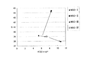
表1に示す各吸着剤MSC−I〜IVにおける分離比αと酸素の吸着速度定数K(O2)との関係を示す図6から理解できるように、MSC−IIIからMSC−IVへ向かう矢印のように、酸素の吸着速度定数K(O2)が僅かに大きくなっただけでは十分な効果が得られず、MSC−III及びMSC−IVからMSC−IIに向かう矢印のように、酸素の吸着速度定数K(O2)は僅かに大きくなるだけであるが分離比αが大きくなると、低純度窒素ガス発生方法での能力が大幅に向上し、さらに、MSC−III及びMSC−IVからMSC−Iに向かう矢印のように、分離比αは僅かに劣るものの酸素の吸着速度定数K(O2)が大きい場合には、低純度窒素ガス発生方法での能力が向上する。 As can be understood from FIG. 6 showing the relationship between the separation ratio α and the adsorption rate constant K (O 2 ) of oxygen in each of the adsorbents MSC-I to IV shown in Table 1, an arrow heading from MSC-III to MSC-IV As described above, a sufficient effect cannot be obtained if the oxygen adsorption rate constant K (O 2 ) is slightly increased. As indicated by arrows from MSC-III and MSC-IV to MSC-II, The adsorption rate constant K (O 2 ) is only slightly increased, but when the separation ratio α is increased, the ability of the low-purity nitrogen gas generation method is greatly improved. Further, from MSC-III and MSC-IV to MSC As shown by the arrow toward -I, the separation ratio α is slightly inferior, but when the oxygen adsorption rate constant K (O 2 ) is large, the ability in the low-purity nitrogen gas generation method is improved.
したがって、酸素と窒素との分離比αが37.9以上で、かつ、酸素の吸着速度定数が8.5×10⁻²sec−1以上の吸着剤を使用することにより、SV=1500〜2500hr−1で、PSA装置からの製品窒素の取出能力220Nm3/hr以上を達成することが可能となり、窒素発生効率をより高めることができる。なお、MSC−IIIやMSC−IVを用いることも可能であるが、吸着剤の充填量が多くなるため、吸着剤価格や吸着筒価格が高くなり、装置寸法が大きくなるため、特に船舶用としては不適当であるといえる。 Therefore, by using an adsorbent having an oxygen / nitrogen separation ratio α of 37.9 or more and an oxygen adsorption rate constant of 8.5 × 10 −2 sec −1 or more, SV = 1500 to 2500 hr. −1 , it becomes possible to achieve a product nitrogen extraction capacity of 220 Nm 3 / hr or more from the PSA apparatus, and the nitrogen generation efficiency can be further increased. Although it is possible to use MSC-III or MSC-IV, since the amount of adsorbent increases, the adsorbent price and the adsorption cylinder price increase, and the size of the apparatus increases. Is inappropriate.
次にSV値に関しては、SV値を大きくし過ぎると切替時間が短くなるため、再生時間も短くなって再生不足となり、逆に、SV値を小さくし過ぎると切替時間中の最大圧力(吸着圧力最大値)が原料空気圧力まで到達しなくなるため、SV値も最適な範囲を選定する必要がある。表4は、原料空気圧力を0.98MPaとし、SV値を変化させたときの各吸着剤における吸着圧力最大値を測定した結果を示している。
この結果から、MSC−I、MSC−IIの場合は、SV=1750hr−1より小さくなると、吸着圧力最大値は徐々に減少し、SV=1250hr−1から顕著に減少している。このため、十分に吸着剤の性能を発揮するためには、SV値は1500〜2500hr−1の範囲が適当であり、原料空気圧力を0.7MPa以上、特に、0.9MPa以上に設定して吸着圧力最大値を十分に上昇させるべきであることがわかる。また、MSC−III,MSC−IVについては、O2の吸着速度定数が小さいため、酸素が吸着剤に吸着され難く製品窒素ガス側に酸素が破過してしまうため、吸着圧力は上がっているが窒素純度が低下してしまう。なお、原料空気圧力を1.0MPaを超える圧力にすると、装置の耐圧を考慮しなければならず、不経済となる。 From this result, in the case of MSC-I and MSC-II, when it becomes smaller than SV = 1750 hr −1 , the maximum adsorption pressure value gradually decreases and significantly decreases from SV = 1250 hr −1 . For this reason, in order to sufficiently exhibit the performance of the adsorbent, the SV value is suitably in the range of 1500 to 2500 hr −1 , and the raw material air pressure is set to 0.7 MPa or more, particularly 0.9 MPa or more. It can be seen that the maximum adsorption pressure should be increased sufficiently. In addition, as for MSC-III and MSC-IV, since the adsorption rate constant of O 2 is small, it is difficult for oxygen to be adsorbed by the adsorbent, and oxygen breaks through to the product nitrogen gas side, so that the adsorption pressure is increased. However, the purity of nitrogen is lowered. In addition, when the raw material air pressure is set to a pressure exceeding 1.0 MPa, the pressure resistance of the apparatus must be taken into account, which is uneconomical.
また、PSA式窒素発生装置には、製品量を多く取り出すと窒素純度が低下し、少なくすると窒素純度が上昇するという特性があるため、製品中の酸素濃度に応じて最適な製品取出量が存在し、製品中の酸素濃度が3体積%のときには220〜550Nm3/hr・ton、同じく酸素濃度が4体積%のときには280〜630Nm3/hr・ton、同じく酸素濃度が5体積%のときには340〜700Nm3/hr・tonが装置からの最適な製品取出量となる。 In addition, since the PSA nitrogen generator has the characteristic that the nitrogen purity decreases when a large amount of product is taken out and the nitrogen purity increases when it is reduced, there is an optimal amount of product extracted according to the oxygen concentration in the product. When the oxygen concentration in the product is 3% by volume, 220 to 550 Nm 3 / hr · ton, similarly when the oxygen concentration is 4% by volume, 280 to 630 Nm 3 / hr · ton, and similarly when the oxygen concentration is 5% by volume, 340 ˜700 Nm 3 / hr · ton is the optimum product removal amount from the apparatus.
したがって、船舶における防爆用のパージガスやシールガスとして使用する酸素濃度が3〜5体積%の低純度窒素ガスを供給するための窒素PSA装置を運転する方法としては、吸着圧力最大値を十分に高めるために原料空気圧力を0.7〜1.0MPaの範囲、好ましくは0.9〜1.0MPaの範囲に設定し、適切な切替時間とするためにSV値を1500〜2500hr−1の範囲に設定するとともに、装置からの製品取出量(能力)は、製品中の酸素濃度が3体積%のときには220〜550Nm3/hr・ton、同じく酸素濃度が4体積%のときには280〜630Nm3/hr・ton、同じく酸素濃度が5体積%のときには340〜700Nm3/hr・tonの範囲にそれぞれ設定することにより、3〜5体積%の低純度窒素ガスを効率よく発生させることができ、窒素PSA装置の小型化、分子ふるい炭素使用量の低減、装置価格の低減を図ることができる。 Therefore, as a method for operating a nitrogen PSA apparatus for supplying low purity nitrogen gas having an oxygen concentration of 3 to 5% by volume used as an explosion-proof purge gas or seal gas in a ship, the adsorption pressure maximum value is sufficiently increased. Therefore, the raw material air pressure is set in the range of 0.7 to 1.0 MPa, preferably in the range of 0.9 to 1.0 MPa, and the SV value is set in the range of 1500 to 2500 hr −1 in order to obtain an appropriate switching time. and sets, product take-off (ability) from devices, 220~550Nm 3 / hr · ton when the oxygen concentration in the product is 3% by volume, also when the oxygen concentration of 4 vol% 280~630Nm 3 / hr Ton, similarly, when the oxygen concentration is 5% by volume, by setting within the range of 340 to 700 Nm 3 / hr Purity nitrogen gas can be generated efficiently, and the size of the nitrogen PSA device can be reduced, the amount of molecular sieve carbon used can be reduced, and the device price can be reduced.
吸着剤としてMSC−Iを充填した大陽日酸株式会社製PSA装置(吸着剤充填量200kg/筒)と圧縮機2台(アトラスコプコ製GA37AFF及び日立製作所製OSPN−22)とを組み合わせで実機規模での実験を行った。原料空気圧力は0.9MPa、SV値は1720hr−1、切替時間は30秒にそれぞれ設定した。製品窒素ガス中の酸素濃度を5体積%としたときの窒素発生能力は635Nm3/hr・tonであった。 PSA device made by Taiyo Nippon Sanso Co., Ltd. filled with MSC-I as an adsorbent (adsorbent filling amount 200 kg / cylinder) and two compressors (Atlas Copco GA37AFF and Hitachi OSPN-22) Experiments on a scale were performed. The raw material air pressure was set to 0.9 MPa, the SV value was set to 1720 hr −1 , and the switching time was set to 30 seconds. The nitrogen generation capacity when the oxygen concentration in the product nitrogen gas was 5% by volume was 635 Nm 3 / hr · ton.
A,B…吸着筒、11…空気圧縮機、12…空気貯槽、13…製品タンク、14a…第1入口弁、14b…第2入口弁、15a…第1排気弁、15b…第2排気弁、16…パージ弁、17…上部均圧弁、18…下部均圧弁、19a…第1逆止弁、19b…第2逆止弁、20…第1マスフローコントローラ、21…第2マスフローコントローラ、22…流量調整弁、23a…入口側圧力調整弁、23b…出口側圧力調整弁、24,25,26…圧力計、27…酸素濃度計 A, B ... Adsorption cylinder, 11 ... Air compressor, 12 ... Air storage tank, 13 ... Product tank, 14a ... First inlet valve, 14b ... Second inlet valve, 15a ... First exhaust valve, 15b ... Second exhaust valve , 16 ... purge valve, 17 ... upper pressure equalizing valve, 18 ... lower pressure equalizing valve, 19a ... first check valve, 19b ... second check valve, 20 ... first mass flow controller, 21 ... second mass flow controller, 22 ... Flow rate adjusting valve, 23a ... Inlet side pressure adjusting valve, 23b ... Outlet side pressure adjusting valve, 24, 25, 26 ... Pressure gauge, 27 ... Oxygen concentration meter
Claims (2)
Priority Applications (4)
| Application Number | Priority Date | Filing Date | Title |
|---|---|---|---|
| JP2007149997A JP4972467B2 (en) | 2007-06-06 | 2007-06-06 | Low purity nitrogen gas generation method |
| KR1020080049143A KR101461239B1 (en) | 2007-06-06 | 2008-05-27 | Method of generating low purity nitrogen gas |
| CN200810110637.0A CN101318634B (en) | 2007-06-06 | 2008-06-06 | Low-purity nitrogen gas producing method |
| HK09103614.1A HK1123786A1 (en) | 2007-06-06 | 2009-04-20 | A method for generation of low purity nitrogen gas |
Applications Claiming Priority (1)
| Application Number | Priority Date | Filing Date | Title |
|---|---|---|---|
| JP2007149997A JP4972467B2 (en) | 2007-06-06 | 2007-06-06 | Low purity nitrogen gas generation method |
Publications (2)
| Publication Number | Publication Date |
|---|---|
| JP2008303089A JP2008303089A (en) | 2008-12-18 |
| JP4972467B2 true JP4972467B2 (en) | 2012-07-11 |
Family
ID=40178947
Family Applications (1)
| Application Number | Title | Priority Date | Filing Date |
|---|---|---|---|
| JP2007149997A Active JP4972467B2 (en) | 2007-06-06 | 2007-06-06 | Low purity nitrogen gas generation method |
Country Status (4)
| Country | Link |
|---|---|
| JP (1) | JP4972467B2 (en) |
| KR (1) | KR101461239B1 (en) |
| CN (1) | CN101318634B (en) |
| HK (1) | HK1123786A1 (en) |
Families Citing this family (11)
| Publication number | Priority date | Publication date | Assignee | Title |
|---|---|---|---|---|
| JP5917169B2 (en) | 2012-01-30 | 2016-05-11 | 大陽日酸株式会社 | Nitrogen-enriched gas production method, gas separation method, and nitrogen-enriched gas production apparatus |
| KR101200100B1 (en) * | 2012-05-06 | 2012-11-12 | 이경우 | Nitrogen generating, storage and supply system for tanker ship and control method thereof |
| CN102976291A (en) * | 2012-11-16 | 2013-03-20 | 浙江莱德桑机械有限公司 | Variable pressure adsorption nitrogen production equipment and method thereof |
| KR101722080B1 (en) * | 2014-11-18 | 2017-03-31 | 플로우테크 주식회사 | Nitrogen gas supply system for storage tank and the method thereof |
| JP5870341B1 (en) * | 2015-05-29 | 2016-02-24 | 株式会社フクハラ | Marine explosion-proof purge gas supply system |
| GB2547672B (en) * | 2016-02-25 | 2018-02-21 | Rejuvetech Ltd | System and method |
| CN106276823B (en) * | 2016-10-14 | 2018-10-23 | 北京石油化工工程有限公司 | Low dew point swing adsorption nitrogen producing apparatus and technological process |
| US10744450B2 (en) | 2018-08-14 | 2020-08-18 | Air Products And Chemicals, Inc. | Multi-bed rapid cycle kinetic PSA |
| US10730006B2 (en) | 2018-08-14 | 2020-08-04 | Air Products And Chemicals, Inc. | Port separation for rotary bed PSA |
| US10835856B2 (en) * | 2018-08-14 | 2020-11-17 | Air Products And Chemicals, Inc. | Carbon molecular sieve adsorbent |
| WO2024015292A1 (en) * | 2022-07-12 | 2024-01-18 | ExxonMobil Technology and Engineering Company | Oxygen-enriched combustion for natural gas combined cycle operation |
Family Cites Families (8)
| Publication number | Priority date | Publication date | Assignee | Title |
|---|---|---|---|---|
| JPH0194915A (en) * | 1987-10-02 | 1989-04-13 | Kuraray Chem Corp | Separation of gaseous nitrogen by pressure fluctuation absorption system |
| JP2623487B2 (en) * | 1990-02-10 | 1997-06-25 | 鐘紡株式会社 | Nitrogen gas separation method |
| CN1100605C (en) * | 1995-04-27 | 2003-02-05 | 日本酸素株式会社 | Carbonaceous adsorbent, process for producing same, and method and apparatus for gas separation |
| JP3604820B2 (en) * | 1996-06-26 | 2004-12-22 | カネボウ株式会社 | Pressure swing adsorption type nitrogen gas generator |
| JP3630564B2 (en) * | 1998-07-31 | 2005-03-16 | 東洋ゴム工業株式会社 | Concentrated nitrogen production method |
| JP3553568B2 (en) * | 2001-08-29 | 2004-08-11 | 日本酸素株式会社 | Adsorbent for separating nitrogen from oxygen / nitrogen mixed gas and method for producing nitrogen using the same |
| JP4780903B2 (en) * | 2003-06-10 | 2011-09-28 | エア・ウォーター・ベルパール株式会社 | Separation method of nitrogen gas using molecular sieve carbon |
| CN100400140C (en) * | 2004-11-22 | 2008-07-09 | 四川天一科技股份有限公司 | Pressure swing absorption method for preparing nitrogen from air |
-
2007
- 2007-06-06 JP JP2007149997A patent/JP4972467B2/en active Active
-
2008
- 2008-05-27 KR KR1020080049143A patent/KR101461239B1/en active IP Right Grant
- 2008-06-06 CN CN200810110637.0A patent/CN101318634B/en active Active
-
2009
- 2009-04-20 HK HK09103614.1A patent/HK1123786A1/en not_active IP Right Cessation
Also Published As
| Publication number | Publication date |
|---|---|
| JP2008303089A (en) | 2008-12-18 |
| KR20080107262A (en) | 2008-12-10 |
| HK1123786A1 (en) | 2009-06-26 |
| KR101461239B1 (en) | 2014-11-12 |
| CN101318634A (en) | 2008-12-10 |
| CN101318634B (en) | 2014-12-10 |
Similar Documents
| Publication | Publication Date | Title |
|---|---|---|
| JP4972467B2 (en) | Low purity nitrogen gas generation method | |
| JP3553568B2 (en) | Adsorbent for separating nitrogen from oxygen / nitrogen mixed gas and method for producing nitrogen using the same | |
| JP5917169B2 (en) | Nitrogen-enriched gas production method, gas separation method, and nitrogen-enriched gas production apparatus | |
| JP4898194B2 (en) | Pressure fluctuation adsorption gas separation method and separation apparatus | |
| JP3899282B2 (en) | Gas separation method | |
| JP5902920B2 (en) | Nitrogen gas production method, gas separation method and nitrogen gas production apparatus | |
| KR20130129278A (en) | Method for recovering high-value components from waste gas streams adsorption | |
| JPS63166702A (en) | Concentration of oxygen gas | |
| AU2014227178A1 (en) | Methane gas concentration method | |
| JP5901849B2 (en) | Method for separating methane and nitrogen | |
| TWI680791B (en) | Purification method and purification system for helium gas | |
| JP4469841B2 (en) | Oxygen generator and control method thereof | |
| WO2017048742A1 (en) | Pressure swing adsorption process and apparatus for purifying a hydrogen-containing gas stream | |
| JP5518503B2 (en) | High pressure and high purity nitrogen gas supply device and supply method | |
| US20230356141A1 (en) | Gas separation method and gas separation device | |
| JPH03207420A (en) | Separation of gaseous nitrogen | |
| JP4761635B2 (en) | Nitrogen gas generation method | |
| KR102156825B1 (en) | Pressure swing adsorption process for separation and recovery of carbon monoxide | |
| JP4908997B2 (en) | Pressure fluctuation adsorption gas separation method and separation apparatus | |
| WO2023171786A1 (en) | Gas purification device | |
| JP5602394B2 (en) | Method for producing high purity nitrogen gas | |
| JP2015110796A (en) | Method and apparatus for removing nitrogen from gas including methane as main component | |
| JPS6380821A (en) | Operation for separating gas by variable pressure adsorption |
Legal Events
| Date | Code | Title | Description |
|---|---|---|---|
| A621 | Written request for application examination |
Free format text: JAPANESE INTERMEDIATE CODE: A621 Effective date: 20100524 |
|
| A977 | Report on retrieval |
Free format text: JAPANESE INTERMEDIATE CODE: A971007 Effective date: 20110725 |
|
| A131 | Notification of reasons for refusal |
Free format text: JAPANESE INTERMEDIATE CODE: A131 Effective date: 20110802 |
|
| TRDD | Decision of grant or rejection written | ||
| A01 | Written decision to grant a patent or to grant a registration (utility model) |
Free format text: JAPANESE INTERMEDIATE CODE: A01 Effective date: 20120403 |
|
| A01 | Written decision to grant a patent or to grant a registration (utility model) |
Free format text: JAPANESE INTERMEDIATE CODE: A01 |
|
| A61 | First payment of annual fees (during grant procedure) |
Free format text: JAPANESE INTERMEDIATE CODE: A61 Effective date: 20120409 |
|
| FPAY | Renewal fee payment (event date is renewal date of database) |
Free format text: PAYMENT UNTIL: 20150413 Year of fee payment: 3 |
|
| R150 | Certificate of patent or registration of utility model |
Ref document number: 4972467 Country of ref document: JP Free format text: JAPANESE INTERMEDIATE CODE: R150 Free format text: JAPANESE INTERMEDIATE CODE: R150 |
|
| FPAY | Renewal fee payment (event date is renewal date of database) |
Free format text: PAYMENT UNTIL: 20150413 Year of fee payment: 3 |
|
| R250 | Receipt of annual fees |
Free format text: JAPANESE INTERMEDIATE CODE: R250 |
|
| R250 | Receipt of annual fees |
Free format text: JAPANESE INTERMEDIATE CODE: R250 |
|
| R250 | Receipt of annual fees |
Free format text: JAPANESE INTERMEDIATE CODE: R250 |
|
| R250 | Receipt of annual fees |
Free format text: JAPANESE INTERMEDIATE CODE: R250 |
|
| R250 | Receipt of annual fees |
Free format text: JAPANESE INTERMEDIATE CODE: R250 |
|
| S111 | Request for change of ownership or part of ownership |
Free format text: JAPANESE INTERMEDIATE CODE: R313111 |
|
| R350 | Written notification of registration of transfer |
Free format text: JAPANESE INTERMEDIATE CODE: R350 |
|
| R250 | Receipt of annual fees |
Free format text: JAPANESE INTERMEDIATE CODE: R250 |
|
| R250 | Receipt of annual fees |
Free format text: JAPANESE INTERMEDIATE CODE: R250 |
|
| R250 | Receipt of annual fees |
Free format text: JAPANESE INTERMEDIATE CODE: R250 |
|
| R250 | Receipt of annual fees |
Free format text: JAPANESE INTERMEDIATE CODE: R250 |