JP4970122B2 - Vision test device - Google Patents
Vision test device Download PDFInfo
- Publication number
- JP4970122B2 JP4970122B2 JP2007112423A JP2007112423A JP4970122B2 JP 4970122 B2 JP4970122 B2 JP 4970122B2 JP 2007112423 A JP2007112423 A JP 2007112423A JP 2007112423 A JP2007112423 A JP 2007112423A JP 4970122 B2 JP4970122 B2 JP 4970122B2
- Authority
- JP
- Japan
- Prior art keywords
- target
- distance
- inspection
- screen
- projection
- Prior art date
- Legal status (The legal status is an assumption and is not a legal conclusion. Google has not performed a legal analysis and makes no representation as to the accuracy of the status listed.)
- Active
Links
- 230000004438 eyesight Effects 0.000 title claims description 6
- 238000012360 testing method Methods 0.000 title description 22
- 238000007689 inspection Methods 0.000 claims description 113
- 238000009434 installation Methods 0.000 claims description 62
- 238000005286 illumination Methods 0.000 claims description 37
- 230000004304 visual acuity Effects 0.000 claims description 36
- 230000003287 optical effect Effects 0.000 claims description 25
- 230000000007 visual effect Effects 0.000 claims description 20
- 238000003384 imaging method Methods 0.000 claims description 9
- 238000001514 detection method Methods 0.000 claims description 8
- 230000015572 biosynthetic process Effects 0.000 claims description 2
- 238000011179 visual inspection Methods 0.000 claims 1
- 239000004973 liquid crystal related substance Substances 0.000 description 4
- 238000000034 method Methods 0.000 description 4
- 230000005540 biological transmission Effects 0.000 description 2
- 230000003247 decreasing effect Effects 0.000 description 2
- 238000010586 diagram Methods 0.000 description 2
- 230000004907 flux Effects 0.000 description 2
- VYZAMTAEIAYCRO-UHFFFAOYSA-N Chromium Chemical compound [Cr] VYZAMTAEIAYCRO-UHFFFAOYSA-N 0.000 description 1
- 230000032683 aging Effects 0.000 description 1
- 229910052804 chromium Inorganic materials 0.000 description 1
- 239000011651 chromium Substances 0.000 description 1
- 230000006866 deterioration Effects 0.000 description 1
- 239000011521 glass Substances 0.000 description 1
- 229910052736 halogen Inorganic materials 0.000 description 1
- 150000002367 halogens Chemical class 0.000 description 1
- 238000002834 transmittance Methods 0.000 description 1
- 239000012780 transparent material Substances 0.000 description 1
- 238000007740 vapor deposition Methods 0.000 description 1
Images


Classifications
-
- A—HUMAN NECESSITIES
- A61—MEDICAL OR VETERINARY SCIENCE; HYGIENE
- A61B—DIAGNOSIS; SURGERY; IDENTIFICATION
- A61B3/00—Apparatus for testing the eyes; Instruments for examining the eyes
- A61B3/02—Subjective types, i.e. testing apparatus requiring the active assistance of the patient
- A61B3/028—Subjective types, i.e. testing apparatus requiring the active assistance of the patient for testing visual acuity; for determination of refraction, e.g. phoropters
- A61B3/032—Devices for presenting test symbols or characters, e.g. test chart projectors
-
- A—HUMAN NECESSITIES
- A61—MEDICAL OR VETERINARY SCIENCE; HYGIENE
- A61B—DIAGNOSIS; SURGERY; IDENTIFICATION
- A61B3/00—Apparatus for testing the eyes; Instruments for examining the eyes
- A61B3/02—Subjective types, i.e. testing apparatus requiring the active assistance of the patient
- A61B3/028—Subjective types, i.e. testing apparatus requiring the active assistance of the patient for testing visual acuity; for determination of refraction, e.g. phoropters
- A61B3/04—Trial frames; Sets of lenses for use therewith
-
- A—HUMAN NECESSITIES
- A61—MEDICAL OR VETERINARY SCIENCE; HYGIENE
- A61B—DIAGNOSIS; SURGERY; IDENTIFICATION
- A61B3/00—Apparatus for testing the eyes; Instruments for examining the eyes
Description
本発明は、離れたスクリーンに視力検査用の視標を投影し、被検者眼の視力を検査する視力検査装置に関する。 The present invention relates to a visual acuity test apparatus that projects a visual test for visual acuity on a remote screen and inspects the visual acuity of a subject's eye.
被検者から所定の検査距離の位置に置かれたスクリーンに視力検査視標を投影する投影式の視力検査装置が知られている。投影式の装置ではスクリーンと装置の位置場所によって視標の投影距離(設置距離)が変わるため、装置の設置後、投影レンズを移動させ、設置距離及び検査距離(スクリーンから被検者までの距離)に応じた所定の大きさの視標像がスクリーンに投影されるように調整が行われる(例えば、特許文献1参照)。また、視標像の大きさを変える方式には、特許文献1のような設置距離と検査距離が同じである場合のみに対応する固定倍式の他、複数の投影レンズを移動させることにより、スクリーン上の視標像の大きさをズーム可変する変倍式のものがある(例えば、特許文献2参照)。
ところで、固定倍式の装置においては、装置を設置した距離にて検査に必要な視標サイズが一義的に決まり、特許文献1では視標の結像位置の変更に対して視標の投影光量が調整されるように構成されている。変倍式の装置においては、ある検査距離に対して装置の設置距離を検査距離よりも遠く又は近くに変えられる。変倍式の装置においても、特許文献1と同じように視標サイズの変更に応じて視標の投影光量が調整されてきた。 By the way, in the fixed magnification type apparatus, the target size required for the inspection is uniquely determined by the distance at which the apparatus is installed, and in Patent Document 1, the projected light amount of the target with respect to the change of the imaging position of the target. Is configured to be adjusted. In the variable power type apparatus, the installation distance of the apparatus can be changed to be closer or closer than the inspection distance with respect to a certain inspection distance. Also in the variable power device, the projected light amount of the target has been adjusted according to the change of the target size, as in Patent Document 1.
しかしながら、検査距離と投影距離が異なる場合に、スクリーン上の視標サイズに合わせて投影光量を調整したところ、視標像の輝度が異なっていることが新たに分かった。視標像の輝度が変わると、視力検査の基準に適合した一定基準の下での正確な視力検査が行えない。 However, when the inspection distance and the projection distance are different, the projected light quantity is adjusted according to the target size on the screen, and it has been newly found that the brightness of the target image is different. If the brightness of the target image changes, an accurate visual acuity test cannot be performed under a certain standard that matches the visual acuity test standard.
本発明は、上記従来技術の問題点に鑑み、変倍式の装置においても、正確な検査が可能な視力検査装置を提供することを技術課題とする。 In view of the above-described problems of the prior art, an object of the present invention is to provide a visual acuity inspection apparatus capable of performing an accurate inspection even in a variable power type apparatus.
上記課題を解決するために、本発明は以下のような構成を備えることを特徴とする。
(1) 離れた位置に置かれたスクリーンに視力検査用の視標を投影する視力検査装置において、視標を照明する照明光源及び光軸方向に移動可能な複数の投影レンズを持ち、前記投影レンズの移動によって前記スクリーンに対する視力検査装置の設置距離に応じた視標の結像位置及び前記スクリーンに対する被検者の検査距離に応じた視標の結像サイズが変更される変倍式の視標投影光学系と、前記スクリーンに対する視力検査装置の設置距離及び前記スクリーンに対する被検者の検査距離の各設定値を入力する入力手段と、該入力手段により入力された設置距離及び検査距離に基づいて視標の輝度が所定の基準範囲内に入るように前記視標投影光学系の投影光量を調整する調整手段と、を備えることを特徴とする。
(2) (1)の視力検査装置は、設置距離及び検査距離に応じて予め設定された前記照明光源の発光量の調整値を記憶する記憶手段を備え、前記調整手段は、前記入力手段から入力される設置距離及び検査距離の各設定値の信号と前記記憶手段に記憶された調整値とに基づいて前記照明光源の発光量を調整する手段であることを特徴とする。
(3) 離れた位置に置かれたスクリーンに視力検査用の視標を投影する視力検査装置において、視標を照明する照明光源及び光軸方向に移動可能な複数の投影レンズを持ち、前記投影レンズの移動によって前記スクリーンに対する視力検査装置の設置距離に応じた視標の結像位置及び前記スクリーンに対する被検者の検査距離に応じた視標の結像サイズが変更される変倍式の視標投影光学系と、前記複数の投影レンズの移動位置をそれぞれ検知する位置検知手段と、該位置検知手段の検知結果に基づいて視標の輝度が所定の基準範囲内に入るように前記視標投影光学系の視標の投影光量を調整する調整手段と、を備えることを特徴とする。
In order to solve the above problems, the present invention is characterized by having the following configuration.
(1) In the vision testing apparatus for projection of an index distant vision inspection screen placed in position, has a plurality of projection lenses movable in the illumination light source and the optical axis for illuminating the target, the projection A variable magnification type view in which the imaging position of the visual target according to the installation distance of the visual acuity inspection device with respect to the screen and the imaging size of the visual target according to the inspection distance of the subject with respect to the screen are changed by moving the lens a target projection optical system, based on the input means and the installation distance and the test distance inputted by the input means for inputting the setting values of the test distance of the subject with respect to the installation distance and the screen of the visual acuity testing apparatus for the screen Adjusting means for adjusting the projection light quantity of the target projection optical system so that the brightness of the target falls within a predetermined reference range .
(2) The visual acuity inspection device according to (1) includes a storage unit that stores an adjustment value of the light emission amount of the illumination light source set in advance according to an installation distance and an inspection distance, and the adjustment unit includes: It is a means for adjusting the light emission amount of the illumination light source based on the input signals of the set values of the installation distance and the inspection distance and the adjustment value stored in the storage means.
(3) In a visual acuity inspection apparatus for projecting a visual target for visual acuity inspection on a screen placed at a distant position, the projection apparatus has an illumination light source for illuminating the visual target and a plurality of projection lenses movable in the optical axis direction. A variable magnification type view in which the imaging position of the visual target according to the installation distance of the visual acuity inspection device with respect to the screen and the imaging size of the visual target according to the inspection distance of the subject with respect to the screen are changed by moving the lens A target projection optical system; position detection means for detecting the movement positions of the plurality of projection lenses; and the target so that the brightness of the target falls within a predetermined reference range based on the detection result of the position detection means. Adjusting means for adjusting the projection light quantity of the target of the projection optical system.
本発明によれば、変倍式の装置においも、正確な視力検査ができる。 According to the present invention, an accurate visual acuity test can be performed even in a variable power type device.
本発明の実施の形態を図面に基づいて説明する。図1は本実施形態で使用する投影式視力検査装置100の光学系及び制御系の構成を模式的に示した図である。
Embodiments of the present invention will be described with reference to the drawings. FIG. 1 is a diagram schematically showing a configuration of an optical system and a control system of a projection type visual
100は、本実施形態で用いる投影式視力検査装置(投影式視標呈示装置)である。1は照明光源であり、白色LEDが用いられている。2はコンデンサレンズ、8,9は投影レンズである。コンデンサレンズ2と投影レンズ8,9との間にはチャートディスク4、マスク板5が配置される。チャートディスク4はガラス等の透明材料からなる円盤状の板であり、このチャートディスク4の同一円周上には、多数の検査視標がクロム蒸着により形成されている。検査視標はコンデンサレンズ2を介して照明光源1により背後から照明される。チャートディスク4はモータ6により回転され、検査視標の種類を切換える。また、マスク板5は視力検査視に縦列マスク、横列マスク、一文字マスク等のマスクをかけるために用いられる。マスク板5はモータ7により回転され、投影される検査視標にかけるマスクの種類を切換える。スクリーン20は、装置100から3〜6mの間で設置される(設置距離については、後述する)。
照明光源1を出射した光束は、コンデンサレンズ2により集光され、マスク板5及びチャートディスク4を照明する。マスク板5を介して照明された視標は投影レンズ8、9により投影スクリーン20に投影され、被検眼に呈示される。なお、説明の簡便のため図示は略したが、コンデンサレンズ2、投影レンズ8,9は、筒状の部材に収められており、投影レンズ8、9は、部材内部を光軸上に沿って、独立に移動可能な構成となっている。投影レンズ8,9は、装置外部からスライド移動でき、移動後の位置をネジ等で固定できる構成となっている。投影レンズ8、9が図中の矢印に示すように光軸上を移動されることで、照明光源1に照明された検査視標は、スクリーン20に結像されると共に、所定のサイズに調整される。これにより、視標投影光学系が構成され、検査視標はズーム可変にて所期するサイズでスクリーン20に結像される。なお、単体の光学素子でありながら、屈折力が可変である光学素子(例えば、可変焦点レンズ)を用いて、検査視標の投影をズーム可変とする視標投影光学系としてもよい。
The light beam emitted from the illumination light source 1 is condensed by the condenser lens 2 and illuminates the
70は、モータ6,7に信号を送り、チャートディスク4やマスク板5を回転させ、光軸上に所期する検査視標を配置させたり、照明光源1の発光量を制御する制御部である。なお、図示は略したが、制御部70には、コントローラが接続されており、検査視標の切換等は、検者が操作する図示なきコントローラにより行われる。また、制御部70には、電流制御回路が組み込まれており、制御部70の指令に応じて照明光源1である白色LEDに供給される電流量が変更される。これにより、制御部70により照明光源1の発光量が変更(調整)される。
A
71は、制御部70と接続され、スクリーン20と装置100との設置距離(投影距離)と、スクリーン20から被検者までの検査距離の設定値を入力するための距離設定ユニット(入力手段)である。距離設定ユニット71には、設置距離設定ノブ71aと検査距離設定ノブ71bが設けられている。それぞれのノブ71a、71bには、距離が目盛で付されており、ノブを回転させることにより、設置距離等をそれぞれ設定できる構成となっている。距離設定ユニット71により設定された検査距離、設置距離に応じて、制御部70により照明光源1の発光量が変更され、スクリーン20に投影された検査視標の輝度(以下、視標輝度と言う)が、視力検査の規格(基準)に適合するように変更される。これら制御部70、距離設定ユニット71により照明光源1の発光量(視標の投影光量)を調整する調整手段が構成される。各距離の設定についての詳細は後述する。
71 is connected to the
次に、投影式視力検査装置の設置距離及び検査距離に応じて、スクリーン20上での視標のサイズを調整する方法を説明する。図2は、固定倍式の投影式視力検査装置101と本実施形態の変倍式の投影式視力検査装置100の検査視標の投影を模式的に示した側面図である。スクリーン20が位置A又は位置Bに配置され、被検者眼Eからは各々の位置のスクリーン20まで検査距離Lt1,Lt2だけ離れている。また、装置101は、各々のスクリーン20から設置距離Lo1,Lo2だけ離れており、装置100は、各々のスクリーン20から設置距離Lo3,Lo4だけ離れている。図では、説明の簡略化のため、被験者眼Eから位置A又は位置Bに置かれたスクリーン20までの距離を各スクリーン20から鉛直方向に延びた直線で測っている。図中の視標C1〜C4は、その幅でスクリーン20上の視標サイズを模式的に示したものである。また、装置100、101の端を、設置距離を測る際の基準Mとした。先に挙げたように、投影レンズ9は筒状の部材に納められているため、設置距離の基準Mは、筒状部材の先端部に設けられる。投影レンズ8,9が移動され、スクリーン20上に視標が結像された場合、基準Mから設置距離離れた位置が、視標の結像位置となる。このとき、投影レンズ8,9の光軸上の位置が、視標サイズ(検査距離に関連する)及び視標の結像位置(設置距離に関連する)と対応される。
Next, a method of adjusting the size of the visual target on the
なお、検査視標の設置距離は、厳密に言えば、検査視標がスクリーン20に投影される距離、つまり、チャートディスク4からスクリーン20までの距離となる。これは、チャートディスク4の視標が、像としてスクリーン20に結像されることに依っている。しかしながら、検査距離や設置距離(3〜6m)に対して、基準Mとチャートディスク4の距離は、十数cm程度であるため、設置距離の決め方が基準Mからであっても実質的に問題はない。
Strictly speaking, the installation distance of the inspection target is the distance at which the inspection target is projected onto the
図2(a)において、装置101と被検者眼Eは、スクリーン20から等しい距離離れている。図2(a)では、設置距離=検査距離の関係が成り立ち、Lo1=Lt1,Lo2=Lt2となっている。装置101には、図1に図示された移動可能な投影レンズ8又は9が1枚備えられているのみであり、装置101は、チャートディスクの検査視標を設置距離に応じてスクリーン20に結像させる(焦点を合わせる)のみの構成であり、設置距離とスクリーン20上での視標サイズは一意に対応される。つまり、図2(a)に示すように、検査視標は一定の広がり角度を持って、スクリーン20に投影される。
In FIG. 2A, the
なお、図2は模式図であり、厳密には、装置101の投影レンズを光軸上に動かすことで、スクリーン20に視標を結像させるため、装置101からの広がり角は、設置距離によって多少変わる。このため、図2(a)では、設置距離Lo1,Lo2に比例した検査視標C1,C2がそれぞれの位置に配置されたスクリーン20上に形成される。この場合、被検者眼Eは、ほぼ一定の視角で視標(背景も含む視標C1,C2)を見ることができる。
Note that FIG. 2 is a schematic diagram. Strictly speaking, the target lens is imaged on the
一方、図2(b)の変倍式である装置100の場合、装置100と被検者眼Eは、それぞれの位置に配置されたスクリーン20からそれぞれ異なる距離離れている。ここでの設置距離と検査距離の関係は、Lt1<Lo3,Lt2<Lo4となる。このような条件下で、装置100から位置A,Bに配置されたスクリーン20に検査視標をそれぞれ投影する場合には、検査距離Lt1に対する視標C3が視標C1と同じサイズでスクリーン20に結像され、また、検査距離Lt2に対する視標C4が視標C2と同じサイズでスクリーン20に結像される必要がある。
On the other hand, in the case of the
このとき、変倍式の装置100では、投影レンズ8,9を移動させることにより、図2(b)のようにスクリーン20に結像される視標サイズを調整し、光束Z3にて視標C3を,光束Z4にてC4を得るようにしている。この場合、スクリーン上の視標C3のサイズが視標C1のサイズと同じであっても、視標C3のサイズを得るための光束Z3の広がり角度は、被検眼Eと装置100を同じ位置にしたときの光束ZEの広がり角度と異なる。さらに、検査距離を変化させたときにも、検査距離Lt1における光束Z3の広がり角度に対して、検査距離Lt2における光束Z4の広がり角度が異なる。
At this time, in the
なお、検査視標の結像サイズの調整は、検査距離によって予め定めらたサイズ調整用のサンプル視標をスクリーン20の位置に配置し、作業者がサンプル視標と投影した視標が等しい大きさとなるように投影レンズ8,9を移動させることにより行われる。
The adjustment of the imaging size of the inspection target is performed by arranging a sample target for size adjustment determined in advance by the inspection distance at the position of the
このような装置100では、設置距離に応じてスクリーン20上の視標輝度が変化すると共に、スクリーン20に結像させる視標サイズ(検査距離に応じて変えられるスクリーン20上での視標サイズ)によってもスクリーン20での視標輝度が変化することが、新たに分かった。これは、視標C3のサイズと視標C1のサイズを同じにする場合、投影倍率が小さくされることによる輝度のアップに比べ、装置100の設置距離がLo1からLo3に遠くなったことによる輝度のダウンが勝っていることによる。
In such an
次に、装置100の設置距離及び検査距離が変わっても、視標輝度を所定の基準の輝度値に調整する方法について説明する。正確な検査を可能とするために、本装置の視標輝度の基準は、例えば、230±20cd/m2であるとする。本実施形態では、この基準を満たすように、照明光源1の発光量を調整する構成とする。このような基準を満たすように、設置距離と検査距離に応じて、照明光源1の発光量が定められる。ここで、設置距離、検査距離とも3〜6mの間で独立に設定されるものとする。
Next, a method for adjusting the target luminance to a predetermined reference luminance value even when the installation distance and the inspection distance of the
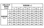
まず、予め設置距離と検査距離とに対応した照明光源1の発光量を定める。設置距離と検査距離を所定のステップ(ここでは、0.5m)にそれぞれ分け、設置距離と検査距離に対する照明光源1の発光量を対応表化する。対応表における照明光源1の発光量から、白色LEDの駆動電流(又は電圧)を算出し、これを図3のような対応表にする。図3は、検査距離と設置距離をそれぞれパラメータとし、各値を設定した際の照明光源1へ供給する電流値を表にしたものである。ここでは、具体的な数値は示さず、表の形式のみ示している。電流値の設定は、照明光源1に利用する白色LEDの特性等に応じて、適宜行えばよい。視標輝度を変更するための各々の設定値を持つ対応表(対応データ)は、制御部70が持つ記憶手段であるメモリ75に記憶させておく。制御部70が、距離設定ユニットの距離設定に応じて、照明光源1への電流量を変更する。
First, the light emission amount of the illumination light source 1 corresponding to the installation distance and the inspection distance is determined in advance. The installation distance and the inspection distance are divided into predetermined steps (here, 0.5 m), and the light emission amount of the illumination light source 1 with respect to the installation distance and the inspection distance is tabulated. The drive current (or voltage) of the white LED is calculated from the light emission amount of the illumination light source 1 in the correspondence table, and this is made into a correspondence table as shown in FIG. FIG. 3 is a table showing the current value supplied to the illumination light source 1 when each value is set with the inspection distance and the installation distance as parameters. Here, specific numerical values are not shown, and only the table format is shown. The current value may be set as appropriate according to the characteristics of the white LED used for the illumination light source 1. A correspondence table (corresponding data) having respective setting values for changing the target luminance is stored in a
以上のような構成を備える投影式視力検査装置において、装置100の設置及び光量調節について説明する。検者又は調整者はスクリーン20から所定距離離れた位置(ここでは5mとする)に装置100を設置する。次に、検査距離を定め(ここでは、4mとする)、投影レンズ8,9の位置を変え、投影される視標像がスクリーン20上に結像するように調整を行う。また、検査距離を加味して、スクリーン20上に結像する視標サイズを先に挙げたサンプル視標を用いて調整する。
In the projection type visual acuity inspection apparatus having the above-described configuration, installation of the
次に、距離設定ユニット71を操作してスクリーン20上に投影される視標輝度を基準の輝度値(ほぼ230cd/m2)とする。設置距離設定ノブ71aを操作して設置距離を5mとし、検査距離設定ノブ71bを操作して検査距離を4mとして設定する。制御部70は、距離設定ユニット71により入力された設定信号に応じて、メモリ75に記憶されている対応表から設定に適合する電流値(調整値)を設定する。制御部70は、照明光源1への供給電流を設定された電流値にすることで、視標輝度を基準の輝度値とする。なお、設置距離等が4.8m等のようなステップに合わない設定値であっても、制御部70は、最も近いステップが設定値になったとして、電流値を設定する。これにより、視標輝度は230±20cd/m2の範囲内に収められる。
Next, the target brightness projected on the
このような光量の調整を行うことにより、設置距離(スクリーン20に対する装置100の位置)及び検査距離(スクリーン20に対する被検者眼Eの位置)がいずれであっても(異なっていても)、検査視標のスクリーン20での輝度は検査の基準に適合したものとなる。これによって、正確な視力検査が行えるようになる。
By adjusting the amount of light, the installation distance (the position of the
なお、以上説明した本実施形態では、制御部70及び距離設定ユニット71にて、調整手段が構成されたが、この形態に限るものではない。作業者による設置距離、検査距離の入力を可変抵抗を用いて行い、抵抗値の変化に伴って、照明光源1に供給される電流値等が変更されることで、投影光量が調整される構成としてもよい。
In the present embodiment described above, the adjusting unit is configured by the
なお、以上説明した本実施形態では、投影レンズ8,9を移動させ、視標をスクリーン20に結像させると共に、検査距離に応じた視標サイズとした後、距離設定ユニット71を操作して、検査輝度を規定値(ここでは、ほぼ230cd/cm2)にする構成としたがこれに限るものではない。投影レンズ8,9の位置に応じて、検査輝度が規定値となる構成や、検査距離や設置距離の各設定値を入力設定することで、検査距離に応じた視標サイズが設定され、視標輝度が基準値に設定される構成としてもよい。
In the present embodiment described above, the
例えば、投影レンズ8,9にそれぞれエンコーダやポテンショメータ等の位置検知手段を取り付け、投影レンズ8,9の移動した位置(例えば、レンズカム内の移動位置等)が制御部70に把握される構成とする。投影レンズ8,9が操作者に移動され、視標サイズを検査距離に応じた大きさとして、スクリーン20に結像されると、制御部70は、位置検知手段からの投影レンズ8,9の位置情報を取得して、現在設定されている検査距離と設置距離を算出し、その設定に適合するように照明光源1の発光量を調整することで、視標輝度が規定値とされる。このとき、制御部70には、投影レンズ8,9の位置情報と検査距離、設置距離の対応表をメモリ75等に記憶させておく。
For example, a position detection unit such as an encoder or a potentiometer is attached to each of the
また、別の例として、投影レンズ8,9をそれぞれ移動させる移動手段となるアクチュエータ等を取り付け、制御部70からの指令により投影レンズ8,9が移動可能な構成とする。距離設定ユニット71にて、検査距離及び設置距離が設定されると、制御部70は、その設定に応じてそれぞれのアクチュエータに指令を送り、投影レンズ8,9を移動させる。投影レンズ8,9が移動されると、視標サイズ及びスクリーン20への視標の結像が、設定した検査距離及び設置距離に対応したものとなり、照明光源1の発光量が調節されて、視標輝度が規定値とされる。このとき、検査距離及び設置距離と投影レンズ8,9の位置の対応表を制御部70のメモリ75等に記憶させておく。
As another example, an actuator or the like serving as a moving means for moving the
このようにして、視標サイズや視標をスクリーン20に結像させる操作か、検査距離及び設置距離を設定する操作のどちらかを行うのみで、視力検査の基準に適合した視標輝度となるように、照明光源1の発光量(投影光量)が調整される。これにより、簡単な操作で正確な視力検査が行える。
In this way, the target luminance is adapted to the eye test standard only by performing either the operation for forming the target size or target on the
なお、以上説明した本実施形態では、距離設定ユニット71による設定は、検査距離と設置距離にて行う構成としたがこれに限るものでない。相対的な設定であってもよい。装置100から被検者眼Eまでの距離を用いる構成でもよい。例えば、設置距離と装置100から被検者眼Eまでの距離を距離設定ユニット71により設定することもできる。
In the above-described embodiment, the setting by the
以上説明した本実施形態では、スクリーン20上の輝度の変更を、照明光源1の発光量を制御部70により制御する構成としたが、これに限るものではない。スクリーン20上での輝度(投影光量)が調整されればよく、照明光源1の発光量を一定とし、投影レンズ8,9に光量絞りを設ける構成としてもよい。例えば、光量絞りを光軸上に移動させる構成や光量絞りの開口を変更する構成である。先に挙げた例のように、光量絞りに位置検知手段や移動手段を取り付け、制御部70の指令に応じて、光量絞りの配置位置を調整する構成としたり、開口を制御する構成とすればよい。このような構成にすれば、照明光源1が発光量により色温度が変わり易い光源、例えば、ハロゲンランプ等であった場合、視標輝度の変化に伴う視標の色味が変わらず、正確な検査が行える。さらに、光量絞りに換えて、遮光部と透光部を有するとともに、その透光比率を変更することのできる円盤を投影光学系内に配置し、透光比率を種々変えて円盤を回転させることにより光量を調整することもできる。
In the present embodiment described above, the change in luminance on the
なお、以上説明した本実施形態では、スクリーンに投影する視標をチャートディスクに作製した検査視標を照明光源1により照明する構成としたがこれに限るものではない。透光体の所定の位置に所定のパターン(ここでは、視標)を形成できる液晶板等を用い、液晶板に形成した視標をスクリーン上に投影する構成としてもよい。このような場合、液晶板の視標のサイズを変えることにより、スクリーン上での視標のサイズを任意に変更できる。また、視標周辺の透過率を変えることにより、視標輝度を変更できる。また、このような構成であれば、チャートディスクやマスク板等を用いることなく、様々な検査視標がスクリーンに投影できる。さらにまた、液晶板等にて検査視標を形成する場合、視標の形を自由に作れるため、投影する視標の歪みの補正(例えば、台形補正)などができる。 In the above-described embodiment, the inspection target in which the target to be projected on the screen is formed on the chart disk is illuminated by the illumination light source 1, but the present invention is not limited to this. A liquid crystal plate or the like that can form a predetermined pattern (here, a target) at a predetermined position of the light transmitting body may be used, and the target formed on the liquid crystal plate may be projected onto the screen. In such a case, the size of the target on the screen can be arbitrarily changed by changing the size of the target on the liquid crystal plate. Moreover, the target luminance can be changed by changing the transmittance around the target. Further, with such a configuration, various inspection targets can be projected on the screen without using a chart disk or a mask plate. Furthermore, when the inspection target is formed with a liquid crystal plate or the like, the shape of the target can be freely created, so that distortion of the projected target can be corrected (for example, trapezoidal correction).
なお、以上説明した本実施形態では、設置距離、検査距離がいずれであっても、視標輝度がほぼ一定となる構成としたが、これに視標輝度の微調整を行う構成を付加してもよい。これは、視標輝度によって検査結果が左右されるため、眼鏡店や眼科医院では、視標輝度を微調整する場合があるためである。例えば、入力設定ユニット71に投影光量を増減させる微調整用ノブを設け、操作者のノブ操作に応じて、視標輝度が数十cd/cm2の範囲で増減する構成とする。これにより、視標輝度が微調整でき、眼鏡店や眼科医院において今まで使用していた既存の視力検査装置と本装置の輝度が多少異なる場合は、今までの装置との検査結果の互換性を持たせることができる。また、眼鏡店や眼科医院で蓄積してきた視標輝度に基づく顧客データ等を有効に利用できる。さらにまた、照明光源1の経年劣化に伴う発光量の変化にも対応できる。
In the present embodiment described above, the target luminance is almost constant regardless of the installation distance and the inspection distance. However, a configuration for finely adjusting the target luminance is added thereto. Also good. This is because the test result depends on the target brightness, and the target brightness may be finely adjusted in a spectacle store or an ophthalmic clinic. For example, the
また、微調整用のノブを設けずに、設置距離設定ノブ71aや検査距離設定ノブ71bを1ステップだけ動かし、投影光量を調整する構成としてもよい。
Further, without providing a fine adjustment knob, the installation
1 照明光源
2 コンデンサレンズ
4 チャートディスク
8,9 投影レンズ
20 スクリーン
70 制御部
71 距離設定ユニット
100、101 投影式視力検査装置
DESCRIPTION OF SYMBOLS 1 Illumination light source 2
Claims (3)
視標を照明する照明光源及び光軸方向に移動可能な複数の投影レンズを持ち、前記投影レンズの移動によって前記スクリーンに対する視力検査装置の設置距離に応じた視標の結像位置及び前記スクリーンに対する被検者の検査距離に応じた視標の結像サイズが変更される変倍式の視標投影光学系と、
前記スクリーンに対する視力検査装置の設置距離及び前記スクリーンに対する被検者の検査距離の各設定値を入力する入力手段と、
該入力手段により入力された設置距離及び検査距離に基づいて視標の輝度が所定の基準範囲内に入るように前記視標投影光学系の投影光量を調整する調整手段と、
を備えることを特徴とする視力検査装置。 In a visual acuity inspection apparatus that projects a visual target for visual acuity inspection on a screen placed at a distant position ,
An illumination light source that illuminates the target and a plurality of projection lenses that can move in the optical axis direction, and the image formation position of the target according to the installation distance of the visual inspection device with respect to the screen by the movement of the projection lens and the screen A variable magnification target projection optical system in which the image forming size of the target is changed according to the examination distance of the subject ,
Input means for inputting setting values of the installation distance of the visual acuity inspection apparatus with respect to the screen and the inspection distance of the subject with respect to the screen ;
Adjusting means for adjusting the projection light quantity of the target projection optical system so that the luminance of the target falls within a predetermined reference range based on the installation distance and the inspection distance input by the input means;
An eyesight inspection apparatus comprising:
Priority Applications (5)
| Application Number | Priority Date | Filing Date | Title |
|---|---|---|---|
| JP2007112423A JP4970122B2 (en) | 2007-04-20 | 2007-04-20 | Vision test device |
| EP08154354A EP1982641A1 (en) | 2007-04-20 | 2008-04-10 | Visual Acuity Testing Apparatus |
| US12/081,479 US7784948B2 (en) | 2007-04-20 | 2008-04-16 | Visual acuity testing apparatus |
| CN2008100929328A CN101288584B (en) | 2007-04-20 | 2008-04-18 | Vision testing device |
| KR1020080036184A KR20080094615A (en) | 2007-04-20 | 2008-04-18 | Visual acuity testing device |
Applications Claiming Priority (1)
| Application Number | Priority Date | Filing Date | Title |
|---|---|---|---|
| JP2007112423A JP4970122B2 (en) | 2007-04-20 | 2007-04-20 | Vision test device |
Publications (3)
| Publication Number | Publication Date |
|---|---|
| JP2008264267A JP2008264267A (en) | 2008-11-06 |
| JP2008264267A5 JP2008264267A5 (en) | 2010-05-20 |
| JP4970122B2 true JP4970122B2 (en) | 2012-07-04 |
Family
ID=39691223
Family Applications (1)
| Application Number | Title | Priority Date | Filing Date |
|---|---|---|---|
| JP2007112423A Active JP4970122B2 (en) | 2007-04-20 | 2007-04-20 | Vision test device |
Country Status (5)
| Country | Link |
|---|---|
| US (1) | US7784948B2 (en) |
| EP (1) | EP1982641A1 (en) |
| JP (1) | JP4970122B2 (en) |
| KR (1) | KR20080094615A (en) |
| CN (1) | CN101288584B (en) |
Families Citing this family (25)
| Publication number | Priority date | Publication date | Assignee | Title |
|---|---|---|---|---|
| US10278579B2 (en) | 2008-11-17 | 2019-05-07 | Eyes4Lives, Inc. | Vision protection method and system thereof |
| JP4888579B2 (en) | 2010-04-21 | 2012-02-29 | パナソニック電工株式会社 | Visual function inspection device |
| JP4873103B2 (en) * | 2011-09-07 | 2012-02-08 | パナソニック電工株式会社 | Visual function inspection program and visual function inspection control device |
| KR101273450B1 (en) * | 2011-10-13 | 2013-06-11 | 주식회사 메디스 | Chart Projector |
| JP5417417B2 (en) * | 2011-11-29 | 2014-02-12 | パナソニック株式会社 | Visual function inspection device |
| US8814360B2 (en) | 2012-02-03 | 2014-08-26 | Kenneth J. Hoffer | Pediatric vision test |
| KR101460648B1 (en) * | 2012-12-11 | 2014-11-12 | 옵토로직스주식회사 | Pattern image projector |
| KR101427109B1 (en) * | 2012-12-11 | 2014-08-07 | 옵토로직스주식회사 | Optical structure of pattern image projector |
| EP3043343A4 (en) * | 2013-09-02 | 2017-04-05 | Sony Corporation | Information processing device, information processing method, and program |
| CN103654708B (en) * | 2013-11-14 | 2015-10-21 | 深圳市斯尔顿科技有限公司 | A kind of hand-held Vission detector |
| CN105303024A (en) * | 2014-06-09 | 2016-02-03 | 吴立中 | Vision protection method and system thereof |
| DE102014009459A1 (en) | 2014-06-25 | 2015-12-31 | Rodenstock Gmbh | Procedure for a visual acuity determination |
| US20160143527A1 (en) * | 2014-11-20 | 2016-05-26 | Gn Otometrics A/S | Head mountable device for measuring eye movement having visible projection means |
| CN104598224A (en) * | 2014-12-26 | 2015-05-06 | 上海沙斐网络科技有限公司 | Vision detection method based on terminal and vision detection terminal |
| WO2017108952A1 (en) * | 2015-12-22 | 2017-06-29 | Koninklijke Philips N.V. | System and method for dynamically adjusting a visual acuity test |
| CN105615821A (en) * | 2016-01-21 | 2016-06-01 | 吉林大学 | Polarization vision testing device |
| CN106073693A (en) * | 2016-06-25 | 2016-11-09 | 利辛县眼病防治所 | A kind of Intelligent eyesight test chart and detection method thereof |
| CN105919549A (en) * | 2016-07-08 | 2016-09-07 | 温州星康医学科技有限公司 | Visual acuity chart device, vision self-testing system and self-testing method |
| CN106137116B (en) * | 2016-08-26 | 2018-05-25 | 四川远瞻智汇科技有限公司 | A kind of vision testing method and device |
| US10413172B2 (en) * | 2017-12-11 | 2019-09-17 | 1-800 Contacts, Inc. | Digital visual acuity eye examination for remote physician assessment |
| CN108888235A (en) * | 2018-05-22 | 2018-11-27 | 苏州佳世达电通有限公司 | Brilliant Eyes frame |
| CN109497925A (en) * | 2018-12-29 | 2019-03-22 | 上海理工大学 | Eye visual function evaluating apparatus and eye Evaluation of visual function |
| CN109893079A (en) * | 2019-04-02 | 2019-06-18 | 山东善林视光科技有限公司 | A kind of shared vision drop base station |
| CN109864698B (en) * | 2019-04-04 | 2021-06-08 | 河南师范大学 | Portable vision tester |
| CN113848663A (en) * | 2020-06-10 | 2021-12-28 | 三赢科技(深圳)有限公司 | Lens module testing device |
Family Cites Families (15)
| Publication number | Priority date | Publication date | Assignee | Title |
|---|---|---|---|---|
| US1698013A (en) * | 1924-09-13 | 1929-01-08 | Zeng Standard Company De | Projection device |
| US3490832A (en) * | 1965-12-27 | 1970-01-20 | Iwao Mitsuishi | Visual acuity testing equipment |
| DE7008479U (en) * | 1970-03-07 | 1971-08-19 | Zeiss Carl Fa | DEVICE FOR MONOCULAR AND BINOCULAR SUBJECTIVE EYE FUNCTIONAL TESTING. |
| FR2235627A5 (en) | 1973-06-29 | 1975-01-24 | Essilor Int | |
| US3969020A (en) * | 1973-12-28 | 1976-07-13 | Giles C. Clegg, Jr. | Automatic refraction apparatus and method |
| US4105302A (en) * | 1976-06-23 | 1978-08-08 | Tate Jr George W | Automatic refraction apparatus and method |
| US4861154A (en) * | 1986-08-06 | 1989-08-29 | Westinghouse Electric Corp. | Automated visual assessment system with steady state visual evoked potential stimulator and product detector |
| US4953968A (en) * | 1986-08-06 | 1990-09-04 | Westinghouse Electric Corp. | Automated visual assessment system with steady visual evoked potential stimulator and product detector |
| US5078486A (en) * | 1989-10-13 | 1992-01-07 | Evans David W | Self-calibrating vision test apparatus |
| JP2801298B2 (en) * | 1989-10-20 | 1998-09-21 | 株式会社トプコン | Subjective inspection device |
| JPH05154105A (en) * | 1991-12-03 | 1993-06-22 | Toto Ltd | Eyesight examining device |
| JPH05261066A (en) * | 1992-03-17 | 1993-10-12 | Topcon Corp | Device for examining visual acuity |
| JP3299809B2 (en) | 1993-03-31 | 2002-07-08 | 株式会社ニデック | Optotype presenting device |
| JP3958958B2 (en) * | 2001-11-30 | 2007-08-15 | 興和株式会社 | Electronics |
| JP3953877B2 (en) * | 2002-04-19 | 2007-08-08 | 株式会社ニデック | Vision test device |
-
2007
- 2007-04-20 JP JP2007112423A patent/JP4970122B2/en active Active
-
2008
- 2008-04-10 EP EP08154354A patent/EP1982641A1/en not_active Withdrawn
- 2008-04-16 US US12/081,479 patent/US7784948B2/en not_active Expired - Fee Related
- 2008-04-18 KR KR1020080036184A patent/KR20080094615A/en not_active Application Discontinuation
- 2008-04-18 CN CN2008100929328A patent/CN101288584B/en active Active
Also Published As
| Publication number | Publication date |
|---|---|
| KR20080094615A (en) | 2008-10-23 |
| CN101288584B (en) | 2011-07-13 |
| EP1982641A1 (en) | 2008-10-22 |
| JP2008264267A (en) | 2008-11-06 |
| US7784948B2 (en) | 2010-08-31 |
| US20080259278A1 (en) | 2008-10-23 |
| CN101288584A (en) | 2008-10-22 |
Similar Documents
| Publication | Publication Date | Title |
|---|---|---|
| JP4970122B2 (en) | Vision test device | |
| US5943118A (en) | Arrangement and method for illumination in a stereoscopic ophthalmic microscope | |
| US4920419A (en) | Zoom lens focus control device for film video player | |
| JP2008264267A5 (en) | ||
| JPWO2009031477A1 (en) | Autofocus device and microscope | |
| US2691918A (en) | Illuminating means for optical instruments | |
| JP2006146243A (en) | Transmitted light base for microscope and method for controlling illumination intensity of transmitted light base | |
| US10171725B1 (en) | Variable focal length lens system including a focus state reference subsystem | |
| JPH11128264A (en) | Ablation rate meter and ablation device with the same | |
| JP2017113572A (en) | Eye-sight inspection device and inspection method of eye | |
| JP2017113573A (en) | Eye-sight inspection device and inspection method of eye | |
| JP2005157340A (en) | Stereoscopic microscope | |
| JP2008209627A (en) | Micro-measuring device | |
| US5270527A (en) | Method for autofocusing of microscopes and autofocusing system for microscopes | |
| JP4250721B2 (en) | Illumination apparatus and method for stereoscopic microscope for ophthalmic examination | |
| JP6818616B2 (en) | Microscope device | |
| JP2002516408A (en) | Apparatus for directly controlling the operation of a zoom system in a stereo microscope | |
| CN103784117A (en) | Ophthalmic apparatus and control method therefor, and camera | |
| JP5453579B2 (en) | Method for automatically adjusting the level of an illumination source in an optical measuring machine | |
| JP3299809B2 (en) | Optotype presenting device | |
| JPH06165755A (en) | Optometry apparatus | |
| JP7099855B2 (en) | Visual indicator presentation device | |
| JPH0546724Y2 (en) | ||
| JP2003310552A (en) | Visual acuity tester | |
| JP4219754B2 (en) | Projector device |
Legal Events
| Date | Code | Title | Description |
|---|---|---|---|
| A521 | Request for written amendment filed |
Free format text: JAPANESE INTERMEDIATE CODE: A523 Effective date: 20100406 |
|
| A621 | Written request for application examination |
Free format text: JAPANESE INTERMEDIATE CODE: A621 Effective date: 20100406 |
|
| A977 | Report on retrieval |
Free format text: JAPANESE INTERMEDIATE CODE: A971007 Effective date: 20120229 |
|
| TRDD | Decision of grant or rejection written | ||
| A01 | Written decision to grant a patent or to grant a registration (utility model) |
Free format text: JAPANESE INTERMEDIATE CODE: A01 Effective date: 20120306 |
|
| A01 | Written decision to grant a patent or to grant a registration (utility model) |
Free format text: JAPANESE INTERMEDIATE CODE: A01 |
|
| A61 | First payment of annual fees (during grant procedure) |
Free format text: JAPANESE INTERMEDIATE CODE: A61 Effective date: 20120404 |
|
| FPAY | Renewal fee payment (event date is renewal date of database) |
Free format text: PAYMENT UNTIL: 20150413 Year of fee payment: 3 |
|
| R150 | Certificate of patent or registration of utility model |
Ref document number: 4970122 Country of ref document: JP Free format text: JAPANESE INTERMEDIATE CODE: R150 Free format text: JAPANESE INTERMEDIATE CODE: R150 |
|
| R250 | Receipt of annual fees |
Free format text: JAPANESE INTERMEDIATE CODE: R250 |
|
| R250 | Receipt of annual fees |
Free format text: JAPANESE INTERMEDIATE CODE: R250 |
|
| R250 | Receipt of annual fees |
Free format text: JAPANESE INTERMEDIATE CODE: R250 |
|
| R250 | Receipt of annual fees |
Free format text: JAPANESE INTERMEDIATE CODE: R250 |
|
| R250 | Receipt of annual fees |
Free format text: JAPANESE INTERMEDIATE CODE: R250 |
|
| R250 | Receipt of annual fees |
Free format text: JAPANESE INTERMEDIATE CODE: R250 |
|
| R250 | Receipt of annual fees |
Free format text: JAPANESE INTERMEDIATE CODE: R250 |
|
| R250 | Receipt of annual fees |
Free format text: JAPANESE INTERMEDIATE CODE: R250 |