JP4969247B2 - Lancet and lancet device equipped with the same - Google Patents
Lancet and lancet device equipped with the same Download PDFInfo
- Publication number
- JP4969247B2 JP4969247B2 JP2006543178A JP2006543178A JP4969247B2 JP 4969247 B2 JP4969247 B2 JP 4969247B2 JP 2006543178 A JP2006543178 A JP 2006543178A JP 2006543178 A JP2006543178 A JP 2006543178A JP 4969247 B2 JP4969247 B2 JP 4969247B2
- Authority
- JP
- Japan
- Prior art keywords
- puncture
- lancet
- fitting
- puncture body
- casing
- Prior art date
- Legal status (The legal status is an assumption and is not a legal conclusion. Google has not performed a legal analysis and makes no representation as to the accuracy of the status listed.)
- Active
Links
Images


Classifications
-
- A—HUMAN NECESSITIES
- A61—MEDICAL OR VETERINARY SCIENCE; HYGIENE
- A61B—DIAGNOSIS; SURGERY; IDENTIFICATION
- A61B5/00—Measuring for diagnostic purposes; Identification of persons
- A61B5/15—Devices for taking samples of blood
- A61B5/150007—Details
- A61B5/150175—Adjustment of penetration depth
- A61B5/150198—Depth adjustment mechanism at the proximal end of the carrier of the piercing element
-
- A—HUMAN NECESSITIES
- A61—MEDICAL OR VETERINARY SCIENCE; HYGIENE
- A61B—DIAGNOSIS; SURGERY; IDENTIFICATION
- A61B5/00—Measuring for diagnostic purposes; Identification of persons
- A61B5/15—Devices for taking samples of blood
- A61B5/150007—Details
- A61B5/150015—Source of blood
- A61B5/150022—Source of blood for capillary blood or interstitial fluid
-
- A—HUMAN NECESSITIES
- A61—MEDICAL OR VETERINARY SCIENCE; HYGIENE
- A61B—DIAGNOSIS; SURGERY; IDENTIFICATION
- A61B5/00—Measuring for diagnostic purposes; Identification of persons
- A61B5/15—Devices for taking samples of blood
- A61B5/150007—Details
- A61B5/150374—Details of piercing elements or protective means for preventing accidental injuries by such piercing elements
- A61B5/150381—Design of piercing elements
- A61B5/150412—Pointed piercing elements, e.g. needles, lancets for piercing the skin
-
- A—HUMAN NECESSITIES
- A61—MEDICAL OR VETERINARY SCIENCE; HYGIENE
- A61B—DIAGNOSIS; SURGERY; IDENTIFICATION
- A61B5/00—Measuring for diagnostic purposes; Identification of persons
- A61B5/15—Devices for taking samples of blood
- A61B5/150007—Details
- A61B5/150374—Details of piercing elements or protective means for preventing accidental injuries by such piercing elements
- A61B5/150381—Design of piercing elements
- A61B5/150503—Single-ended needles
-
- A—HUMAN NECESSITIES
- A61—MEDICAL OR VETERINARY SCIENCE; HYGIENE
- A61B—DIAGNOSIS; SURGERY; IDENTIFICATION
- A61B5/00—Measuring for diagnostic purposes; Identification of persons
- A61B5/15—Devices for taking samples of blood
- A61B5/150007—Details
- A61B5/150374—Details of piercing elements or protective means for preventing accidental injuries by such piercing elements
- A61B5/150534—Design of protective means for piercing elements for preventing accidental needle sticks, e.g. shields, caps, protectors, axially extensible sleeves, pivotable protective sleeves
- A61B5/150541—Breakable protectors, e.g. caps, shields or sleeves, i.e. protectors separated destructively, e.g. by breaking a connecting area
- A61B5/150549—Protectors removed by rotational movement, e.g. torsion or screwing
-
- A—HUMAN NECESSITIES
- A61—MEDICAL OR VETERINARY SCIENCE; HYGIENE
- A61B—DIAGNOSIS; SURGERY; IDENTIFICATION
- A61B5/00—Measuring for diagnostic purposes; Identification of persons
- A61B5/15—Devices for taking samples of blood
- A61B5/150007—Details
- A61B5/150374—Details of piercing elements or protective means for preventing accidental injuries by such piercing elements
- A61B5/150534—Design of protective means for piercing elements for preventing accidental needle sticks, e.g. shields, caps, protectors, axially extensible sleeves, pivotable protective sleeves
- A61B5/150541—Breakable protectors, e.g. caps, shields or sleeves, i.e. protectors separated destructively, e.g. by breaking a connecting area
- A61B5/150564—Protectors removed by pulling or pushing
-
- A—HUMAN NECESSITIES
- A61—MEDICAL OR VETERINARY SCIENCE; HYGIENE
- A61B—DIAGNOSIS; SURGERY; IDENTIFICATION
- A61B5/00—Measuring for diagnostic purposes; Identification of persons
- A61B5/15—Devices for taking samples of blood
- A61B5/150007—Details
- A61B5/150374—Details of piercing elements or protective means for preventing accidental injuries by such piercing elements
- A61B5/150534—Design of protective means for piercing elements for preventing accidental needle sticks, e.g. shields, caps, protectors, axially extensible sleeves, pivotable protective sleeves
- A61B5/15058—Joining techniques used for protective means
- A61B5/150618—Integrally moulded protectors, e.g. protectors simultaneously moulded together with a further component, e.g. a hub, of the piercing element
-
- A—HUMAN NECESSITIES
- A61—MEDICAL OR VETERINARY SCIENCE; HYGIENE
- A61B—DIAGNOSIS; SURGERY; IDENTIFICATION
- A61B5/00—Measuring for diagnostic purposes; Identification of persons
- A61B5/15—Devices for taking samples of blood
- A61B5/150007—Details
- A61B5/150374—Details of piercing elements or protective means for preventing accidental injuries by such piercing elements
- A61B5/150534—Design of protective means for piercing elements for preventing accidental needle sticks, e.g. shields, caps, protectors, axially extensible sleeves, pivotable protective sleeves
- A61B5/150694—Procedure for removing protection means at the time of piercing
- A61B5/150717—Procedure for removing protection means at the time of piercing manually removed
-
- A—HUMAN NECESSITIES
- A61—MEDICAL OR VETERINARY SCIENCE; HYGIENE
- A61B—DIAGNOSIS; SURGERY; IDENTIFICATION
- A61B5/00—Measuring for diagnostic purposes; Identification of persons
- A61B5/15—Devices for taking samples of blood
- A61B5/150007—Details
- A61B5/150885—Preventing re-use
- A61B5/150916—Preventing re-use by blocking components, e.g. piston, driving device or fluid passageway
-
- A—HUMAN NECESSITIES
- A61—MEDICAL OR VETERINARY SCIENCE; HYGIENE
- A61B—DIAGNOSIS; SURGERY; IDENTIFICATION
- A61B5/00—Measuring for diagnostic purposes; Identification of persons
- A61B5/15—Devices for taking samples of blood
- A61B5/151—Devices specially adapted for taking samples of capillary blood, e.g. by lancets, needles or blades
- A61B5/15101—Details
- A61B5/15103—Piercing procedure
- A61B5/15107—Piercing being assisted by a triggering mechanism
- A61B5/15113—Manually triggered, i.e. the triggering requires a deliberate action by the user such as pressing a drive button
-
- A—HUMAN NECESSITIES
- A61—MEDICAL OR VETERINARY SCIENCE; HYGIENE
- A61B—DIAGNOSIS; SURGERY; IDENTIFICATION
- A61B5/00—Measuring for diagnostic purposes; Identification of persons
- A61B5/15—Devices for taking samples of blood
- A61B5/151—Devices specially adapted for taking samples of capillary blood, e.g. by lancets, needles or blades
- A61B5/15101—Details
- A61B5/15115—Driving means for propelling the piercing element to pierce the skin, e.g. comprising mechanisms based on shape memory alloys, magnetism, solenoids, piezoelectric effect, biased elements, resilient elements, vacuum or compressed fluids
- A61B5/15117—Driving means for propelling the piercing element to pierce the skin, e.g. comprising mechanisms based on shape memory alloys, magnetism, solenoids, piezoelectric effect, biased elements, resilient elements, vacuum or compressed fluids comprising biased elements, resilient elements or a spring, e.g. a helical spring, leaf spring, or elastic strap
-
- A—HUMAN NECESSITIES
- A61—MEDICAL OR VETERINARY SCIENCE; HYGIENE
- A61B—DIAGNOSIS; SURGERY; IDENTIFICATION
- A61B5/00—Measuring for diagnostic purposes; Identification of persons
- A61B5/15—Devices for taking samples of blood
- A61B5/151—Devices specially adapted for taking samples of capillary blood, e.g. by lancets, needles or blades
- A61B5/15186—Devices loaded with a single lancet, i.e. a single lancet with or without a casing is loaded into a reusable drive device and then discarded after use; drive devices reloadable for multiple use
- A61B5/15188—Constructional features of reusable driving devices
- A61B5/1519—Constructional features of reusable driving devices comprising driving means, e.g. a spring, for propelling the piercing unit
-
- A—HUMAN NECESSITIES
- A61—MEDICAL OR VETERINARY SCIENCE; HYGIENE
- A61B—DIAGNOSIS; SURGERY; IDENTIFICATION
- A61B5/00—Measuring for diagnostic purposes; Identification of persons
- A61B5/15—Devices for taking samples of blood
- A61B5/151—Devices specially adapted for taking samples of capillary blood, e.g. by lancets, needles or blades
- A61B5/15186—Devices loaded with a single lancet, i.e. a single lancet with or without a casing is loaded into a reusable drive device and then discarded after use; drive devices reloadable for multiple use
- A61B5/15188—Constructional features of reusable driving devices
- A61B5/15192—Constructional features of reusable driving devices comprising driving means, e.g. a spring, for retracting the lancet unit into the driving device housing
- A61B5/15194—Constructional features of reusable driving devices comprising driving means, e.g. a spring, for retracting the lancet unit into the driving device housing fully automatically retracted, i.e. the retraction does not require a deliberate action by the user, e.g. by terminating the contact with the patient's skin
Description
本発明は、皮膚から体液等を採取する際に穿刺傷を形成するために使用されるランセットおよびこれを備えたランセットデバイスに関する。 The present invention relates to a lancet used to form a puncture wound when collecting body fluid or the like from skin, and a lancet device including the lancet.
近年、糖尿病患者の増加に伴って、糖尿病患者自身が自宅等において自ら血糖値の測定を行って、血糖値の変動を自己管理するケースが増加している。このような状況に鑑みて、血糖値を測定するための血液を採取する際に、容易に指先等に傷を負わせて測定に必要な血液を採取することが可能な穿刺針を備えたランセットデバイス(穿刺器具)が提供されている。 In recent years, with an increase in the number of diabetic patients, cases of diabetic patients themselves measuring blood glucose levels themselves at home or the like to self-manage fluctuations in blood glucose levels are increasing. In view of such a situation, when collecting blood for measuring blood glucose level, a lancet provided with a puncture needle that can easily damage a fingertip or the like and collect blood necessary for measurement. A device (puncture device) is provided.
ランセットデバイスは、先端部分に穿刺針を搭載しており、先端部分を指先等にあてた状態でばね等の力を利用して穿刺針を発射させ、先端部から0.数mm〜2.0mm程度穿刺針を突出させる。これにより、指先等を切開して傷口から流出する血液を採取して、採取した血液を血糖値計のセンサ部分等に滴下することで、血糖値を測定することができる。 The lancet device has a puncture needle mounted on the tip portion, and the puncture needle is fired using a force of a spring or the like with the tip portion applied to a fingertip or the like. The puncture needle is protruded about several mm to 2.0 mm. Thereby, blood sugar level can be measured by incising a fingertip etc., collecting blood flowing out from the wound, and dropping the collected blood on a sensor portion of the blood glucose meter.
このようなランセットデバイスは、上述のように、患者の指先等に傷口をつくるための穿刺針を備えているため、特に、視力が低下したお年寄り等が、穿刺針の取り扱いを誤って怪我をするおそれがあった。
このため、必要なとき以外は本体部分から穿刺針を露出させない構造を採用した、いわゆる安全ランセットデバイスが提案されてきている(特許文献1参照)。Since such a lancet device is provided with a puncture needle for creating a wound on the patient's fingertip, etc., as described above, particularly elderly people with reduced visual acuity may accidentally injure the puncture needle. There was a risk.
For this reason, a so-called safety lancet device has been proposed that employs a structure in which the puncture needle is not exposed from the main body part except when necessary (see Patent Document 1).
例えば、特許文献1には、2つのコイルばねを使用してこれらのばねの弾性係数を規定することで、通常時は穿刺針をケーシング内から突出しないようにして、安全性を確保している。
しかしながら、上記従来のランセットデバイスでは、以下に示すような問題点を有している。
すなわち、上記公報に開示されたランセットデバイスでは、使用後におけるランセットのケース内における固定が不十分であるため、使用後にケースを振ると穿刺針の固定が外れて針の先端がケースから突出するおそれがある。また、使用後のランセットを誤って再取付した場合には、穿刺針ホルダとの嵌合が中途半端な状態となって穿刺針の先端が突出した状態となって危険である。このため、使用後における高い安全性が確実に確保されているとは言い難い。However, the conventional lancet device has the following problems.
That is, in the lancet device disclosed in the above publication, since the lancet is not sufficiently fixed in the case after use, if the case is shaken after use, the puncture needle may be fixed and the tip of the needle may protrude from the case. There is. Further, when the lancet after use is mistakenly reattached, the fitting with the puncture needle holder is halfway and the tip of the puncture needle protrudes, which is dangerous. For this reason, it is hard to say that high safety is ensured after use.
本発明の課題は、簡易な構成であって、特に、使用後における安全性を確保することが可能なランセットおよびこれを備えたランセットデバイスを提供することにある。 An object of the present invention is to provide a lancet that has a simple configuration and in particular can ensure safety after use, and a lancet device including the lancet.
第1の発明に係るランセットは、穿刺針の先端を所定の穿刺方向へ突出させるための付勢部材を備えた本体部に対して取り付けられるランセットであって、穿刺体と、ケース部と、第1嵌合部とを備えている。穿刺体は、穿刺針と、穿刺針とは反対側の端部に形成されており本体部と連結される連結部とを有している。ケース部は、筒状部と、開口とを有している。筒状部は、穿刺方向において前後に移動可能な状態で穿刺体を収納する。開口は、穿刺針の突出側の前端部に形成されており、穿刺体が挿入され得る。第1嵌合部は、穿刺体の連結部を本体部から分離すると、穿刺方向において前後に移動不能な状態で穿刺体をケース部内で保持する。 A lancet according to a first aspect of the present invention is a lancet attached to a main body portion provided with a biasing member for projecting the tip of a puncture needle in a predetermined puncture direction, the puncture body, a case portion, 1 fitting part. The puncture body has a puncture needle and a connecting portion that is formed at the end opposite to the puncture needle and is connected to the main body. The case part has a cylindrical part and an opening. The tubular portion accommodates the puncture body in a state where it can move back and forth in the puncture direction. Opening is formed in the front end portion of the protruding side of the puncture needle, the puncture body can be inserted. When the connecting portion of the puncture body is separated from the main body portion, the first fitting portion holds the puncture body in the case portion in a state where it cannot move back and forth in the puncture direction.
ここでは、穿刺傷を形成した後、本体部からケース部を取り外すと、穿刺体が第1嵌合部によって穿刺方向において前後に移動不能な状態で強固に保持される。
ここで、第1嵌合部としては、穿刺体の外周に形成された凹部または凸部と、ケース部の穿刺体が収納されている筒状部の内側の面に形成された凸部または凹部との組み合わせ等が考えられる。つまり、本発明のランセットは、本体部から取り外されると、穿刺体に形成された凹部または凸部と、ケース部の筒状部の内側の面に形成された凸部または凹部とが嵌合し、穿刺体が穿刺方向へ移動不能な状態でケース部内において強固に保持される。Here, after the puncture wound is formed, when the case portion is removed from the main body portion, the puncture body is firmly held by the first fitting portion in a state in which it cannot move back and forth in the puncture direction.
Here, as a 1st fitting part, the recessed part or convex part formed in the outer periphery of a puncture body, and the convex part or recessed part formed in the inner surface of the cylindrical part in which the puncture body of a case part is accommodated A combination with can be considered. That is, when the lancet of the present invention is removed from the main body, the concave portion or convex portion formed in the puncture body and the convex portion or concave portion formed on the inner surface of the cylindrical portion of the case portion are fitted. The puncture body is firmly held in the case portion in a state in which the puncture body cannot move in the puncture direction.
これにより、穿刺傷を形成した後、本体部から取り外されて廃棄される際に、穿刺針の先端を覆うキャップをはめなくても穿刺体の先端から穿刺針が突出することを防止することができる。この結果、簡易な構成であっても、ランセットを廃棄する際に、誤って穿刺体の先端から突出した穿刺針によって使用者が怪我をしたり、使用済の穿刺針に付着した体液等によって病気に感染したりする等の危険を回避することができる。また、使用済みのランセットを誤って再度本体部へ装着してしまった場合でも、一旦本体部から取り外されると第1嵌合部によって穿刺方向に移動不能な状態で穿刺体が強固に保持されているため、穿刺針が発射されることを禁止することができる。よって、汚れた穿刺針を再使用することによる感染の危険性を低減し、より安全性の高いランセットを提供できる。 This prevents the puncture needle from protruding from the tip of the puncture body without the cap covering the tip of the puncture needle when the puncture wound is formed and then removed from the main body and discarded. it can. As a result, even when the lancet is discarded, the user may be injured by the puncture needle that protrudes from the tip of the puncture body, or the body fluid attached to the used puncture needle may cause illness. It is possible to avoid dangers such as infection. In addition, even if a used lancet is accidentally attached to the main body, once the lancet is removed from the main body, the puncture body is firmly held in a state in which it cannot move in the puncture direction by the first fitting portion. Therefore, firing of the puncture needle can be prohibited. Therefore, the risk of infection caused by reusing a dirty puncture needle can be reduced, and a safer lancet can be provided.
第2の発明に係るランセットは、第1の発明に係るランセットであって、使用前の穿刺体を穿刺方向において前後に移動不能に保持する第2嵌合部をさらに備えている。
ここでは、第2嵌合部によって、使用前の穿刺体をケース内において穿刺方向に前後に移動不能な状態で保持する。
これにより、使用前に穿刺体がケース内で穿刺方向に移動しないように保持することができるため、使用前の安全性も確保できる。
なお、第2嵌合部は、第1嵌合部と同様に、穿刺体の外周に形成された凹部または凸部と、ケース部の穿刺体が収納されている筒状部の内側の面に形成された凸部または凹部との組み合わせ等であればよい。The lancet according to the second invention is the lancet according to the first invention, further comprising a second fitting portion that holds the puncture body before use in a puncture direction so as not to move forward and backward.
Here, the puncture body before use is held in the case in a state in which it cannot move back and forth in the puncture direction in the case by the second fitting portion.
Thereby, since it can hold | maintain so that a puncture body may not move to a puncture direction within a case before use, the safety | security before use is also securable.
As with the first fitting portion, the second fitting portion is formed on a concave portion or a convex portion formed on the outer periphery of the puncture body and an inner surface of the cylindrical portion in which the puncture body of the case portion is accommodated. What is necessary is just the combination with the formed convex part or a recessed part.
第3の発明に係るランセットは、第2の発明に係るランセットであって、第2嵌合部は、穿刺針の先端を覆うように穿刺体の先端側に取り付けられたキャップ部と、筒状部の内側の面と、に形成された凸部と凹部とを組み合わせて構成される。
ここでは、使用前に穿刺体を穿刺方向に移動不能な状態で保持する第2嵌合部が、穿刺体の先端部分に取り付けられたキャップ部と、ケース部の筒状部の内側の面に形成された1組の凸部と凹部とで構成されている。A lancet according to a third invention is the lancet according to the second invention, wherein the second fitting portion is a cap portion attached to the distal end side of the puncture body so as to cover the distal end of the puncture needle, and a tubular shape It is comprised combining the convex part and recessed part which were formed in the inner surface of a part.
Here, the second fitting part that holds the puncture body in a state in which the puncture body cannot move in the puncture direction before use is provided on the inner surface of the cap part attached to the distal end portion of the puncture body and the cylindrical part of the case part. It is composed of a pair of formed convex portions and concave portions.
これにより、使用時にはキャップを穿刺体の先端部分から切り離すことで、同時に穿刺体の穿刺方向における保持を解除することができる。
なお、上記凸部と凹部とは、キャップ部に凸部、筒状部の内側の面に凹部が形成されていてもよいし、その反対であってもよい。Thereby, at the time of use, the holding | maintenance in the puncture direction of a puncture body can be cancelled | released simultaneously by separating a cap from the front-end | tip part of a puncture body.
In addition, the said convex part and a recessed part may be formed with the convex part in the cap part, and the recessed part may be formed in the inner surface of the cylindrical part, and vice versa.
第4の発明に係るランセットは、第3の発明に係るランセットであって、キャップ部は、穿刺体と一体成形されている。
ここでは、キャップと穿刺体とが一体成形されているため、部品点数を削減してコストダウンが図れる。The lancet according to the fourth invention is the lancet according to the third invention, and the cap portion is integrally formed with the puncture body.
Here, since the cap and the puncture body are integrally formed, the number of parts can be reduced and the cost can be reduced.
第5の発明に係るランセットは、第1から第4の発明のいずれか1つに係るランセットであって、第1嵌合部は、穿刺針が再度穿刺方向へ移動することを禁止する強固な嵌合力を有している。
ここでは、第1嵌合部が、一度嵌合すると外れにくい強固な嵌合力を有する。
これにより、使用後には、穿刺針がケースの先端から突出することを確実に禁止して、使用後の安全性をより効果的に確保したランセットを提供することができる。The lancet according to a fifth aspect of the present invention is the lancet according to any one of the first to fourth aspects of the invention, wherein the first fitting portion is a strong member that prohibits the puncture needle from moving again in the puncture direction. It has a fitting force.
Here, the first fitting portion has a strong fitting force that is difficult to come off once fitted.
Thereby, after use, the lancet can be surely prohibited from protruding from the tip of the case, and a lancet that can effectively secure safety after use can be provided.
第6の発明に係るランセットは、第1から第5の発明のいずれか1つに係るランセットであって、第1嵌合部は、開口から穿刺針の先端が突出するように発射する直前の穿刺体の待機位置よりも本体部との接続側で穿刺体を保持する。
ここでは、使用後に本体部から取り外されると穿刺方向において穿刺体を移動不能な状態で保持する第1嵌合部が、穿刺体を発射させる際に穿刺体を待機させる位置よりも本体部との接続側において穿刺体を保持する。
これにより、使用時には穿刺体をケース部内における先端側で移動可能とし、使用後には本体部から取り外される際に穿刺体を本体部との接続側へ移動させることにより、容易に第1嵌合部で穿刺体を保持させることができる。The lancet according to a sixth aspect of the present invention is the lancet according to any one of the first to fifth aspects of the present invention, wherein the first fitting portion is immediately before firing so that the tip of the puncture needle protrudes from the opening. The puncture body is held on the connection side with the main body from the standby position of the puncture body.
Here, when the first fitting portion that holds the puncture body in an unmovable state in the puncture direction when removed from the main body portion after use, the first fitting portion is located closer to the main body portion than the position where the puncture body waits when firing the puncture body. The puncture body is held on the connection side.
Accordingly, the puncture body can be moved on the distal end side in the case portion during use, and the puncture body can be moved to the connection side with the main body portion when removed from the main body portion after use, so that the first fitting portion can be easily moved. Can hold the puncture body.
第7の発明に係るランセットは、第1から第6の発明のいずれか1つに係るランセットであって、第1嵌合部は、穿刺方向に略平行な穿刺体の外周面と、穿刺体が移動するケース部の内周面と、に形成された凸部と凹部とを組み合わせて構成される。
ここでは、穿刺体の外周面とケース部の内周面とに、凸部と凹部あるいは凹部と凸部を形成して組み合わせることで、容易に第1嵌合部を形成することができる。A lancet according to a seventh invention is the lancet according to any one of the first to sixth inventions, wherein the first fitting portion includes an outer peripheral surface of the puncture body substantially parallel to the puncture direction, and a puncture body The inner peripheral surface of the case part to which is moved, and a convex part and a concave part formed on the case part are combined.
Here, a 1st fitting part can be easily formed by forming and combining a convex part and a recessed part or a recessed part and a convex part in the outer peripheral surface of a puncture body, and the internal peripheral surface of a case part.
第8の発明に係るランセットは、第7の発明に係るランセットであって、凸部および凹部の少なくともいずれか一方は、弾性変形することにより互いに嵌合する。
ここでは、第1嵌合部を構成する穿刺体と穿刺体の外周面およびケース部の内周面に形成された凸部、凹部は、穿刺体とケース部とを嵌合させる際に少なくともいずれか一方が弾性変形する。
これにより、嵌合し易く抜けにくい構造の第1嵌合部を構成することができる。The lancet according to the eighth invention is the lancet according to the seventh invention, wherein at least one of the convex portion and the concave portion is fitted into each other by elastic deformation.
Here, at least one of the puncture body and the convex portion formed on the outer peripheral surface of the puncture body and the inner peripheral surface of the case portion and the concave portion constituting the first fitting portion is used when fitting the puncture body and the case portion. One of them is elastically deformed.
Thereby, the 1st fitting part of the structure which is easy to fit and cannot be easily removed can be comprised.
第9の発明に係るランセットは、第1から第8の発明のいずれか1つに係るランセットであって、第1嵌合部は、凹部と、凸部と、を有している。凹部は、穿刺体の外周部に形成されており、本体部との接続側に向かって細くなるテーパー状の突状部に隣接して形成されている。凸部は、筒状部の内側の面に形成されており、凹部と嵌合する。 A lancet according to a ninth aspect is the lancet according to any one of the first to eighth aspects, wherein the first fitting portion has a concave portion and a convex portion. The concave portion is formed on the outer peripheral portion of the puncture body, and is formed adjacent to a tapered protruding portion that narrows toward the connection side with the main body portion. The convex portion is formed on the inner surface of the cylindrical portion and fits into the concave portion.
ここでは、使用後のランセットを本体部から取り外す際に、穿刺体を本体部との接続側へ移動させて、穿刺体の外周部に形成されたテーパー状の突状部の最も突出した部分に隣接して形成された溝部に、筒状部の内側の面に形成された凸部が嵌合して保持される。
このように、テーパー状の突状部を組み合わせることで、テーパー状の細い側から挿入されるため嵌合し易いが、一度嵌合すると抜けにくい嵌合部を形成することができる。Here, when removing the used lancet from the main body, the puncture body is moved to the connection side with the main body, and the taper-shaped protrusion formed on the outer periphery of the puncture body is moved to the most protruding portion. Convex portions formed on the inner surface of the cylindrical portion are fitted and held in the adjacent groove portions.
Thus, by combining the tapered protrusions, it is easy to fit because they are inserted from the tapered thin side, but it is possible to form a fitting part that is difficult to come off once fitted.
第10の発明に係るランセットは、第1から第8の発明のいずれか1つに係るランセットであって、穿刺体の外周部および筒状部の内周面のいずれか一方に形成されたテーパー部を有している。
ここでは、穿刺体の外周部かケース部の筒状部のいずれか一方にテーパー部が形成されているため、嵌合しやすく抜けにくい嵌合部を形成することができる。A lancet according to a tenth invention is a lancet according to any one of the first to eighth inventions, wherein the taper is formed on either the outer peripheral portion of the puncture body or the inner peripheral surface of the tubular portion. Has a part.
Here, since the tapered portion is formed on either the outer peripheral portion of the puncture body or the cylindrical portion of the case portion, it is possible to form a fitting portion that is easy to fit and difficult to come off.
第11の発明にかかるランセットは、第1から第8の発明のいずれか1つに係るランセットであって、第1嵌合部は、穿刺体の外周部に形成された凸部と、筒状部の内側の面に形成されたテーパー部に隣接して設けられており、凸部と嵌合する凹部と、を有している。
ここでは、使用後のランセットを本体部から取り外す際に、穿刺体を本体部との接続側へ移動させて、穿刺体の外周部に形成された凸部が、テーパー状の突状部の最も突出した部分に隣接して形成された凹部に嵌合して保持される。A lancet according to an eleventh invention is a lancet according to any one of the first to eighth inventions, wherein the first fitting portion includes a convex portion formed on the outer peripheral portion of the puncture body, and a tubular shape. And a concave portion that is fitted to the convex portion and is provided adjacent to the tapered portion formed on the inner surface of the portion.
Here, when the lancet after use is removed from the main body, the puncture body is moved to the connection side with the main body, and the protrusion formed on the outer periphery of the puncture body is the most of the tapered protrusion. It fits and is hold | maintained at the recessed part formed adjacent to the protruded part.
このように、テーパー状の突状部を組み合わせることで、テーパー状の細い側から挿入されるため嵌合し易いが、一度嵌合すると抜けにくい嵌合部を形成することができる。 Thus, by combining the tapered protrusions, it is easy to fit because they are inserted from the tapered thin side, but it is possible to form a fitting part that is difficult to come off once fitted.
第12の発明に係るランセットは、第1から第8の発明のいずれか1つに係るランセットであって、第1嵌合部は、凹部と、凸部と、を有している。凹部は、穿刺体の外周面における穿刺方向と交差する方向に突出する複数の突状部に隣接するように形成されている。凸部は、筒状部の内側の円筒面に形成され、凹部に嵌合する。
ここでは、使用後のランセットを本体部から取り外す際に穿刺体を本体部との接続側へ移動させると、穿刺体の外周部に形成された複数の突状部に隣接するように形成された凹部が、ケース部の筒状部の内側の面に形成された凸部に嵌合して保持される。
このように、穿刺体の外周に沿って複数形成された突状部に隣接する凹部と筒状部の内側に沿って形成された凸部とを組み合わせることで、数点で穿刺体を保持することができるため、嵌合し易くて抜けにくい嵌合部を形成することができる。A lancet according to a twelfth aspect is the lancet according to any one of the first to eighth aspects, wherein the first fitting portion has a concave portion and a convex portion. The recess is formed so as to be adjacent to a plurality of protrusions protruding in a direction intersecting the puncture direction on the outer peripheral surface of the puncture body. A convex part is formed in the cylindrical surface inside a cylindrical part, and fits into a recessed part.
Here, when the puncture body is moved to the connection side with the main body when removing the used lancet from the main body, the lancet is formed so as to be adjacent to the plurality of protrusions formed on the outer periphery of the puncture body The concave portion is fitted and held in a convex portion formed on the inner surface of the cylindrical portion of the case portion.
In this way, the puncture body is held at several points by combining the recesses adjacent to the plurality of protrusions formed along the outer periphery of the puncture body and the projections formed along the inner side of the cylindrical portion. Therefore, it is possible to form a fitting portion that is easy to fit and difficult to come off.
なお、穿刺体の突状部としては、例えば、穿刺方向に垂直な断面が略円形の穿刺体においてその断面が楕円形状となる穿刺体の一部を用いることができる。この場合には、円筒形状のケース部の内側の面に沿って形成された凸部に、断面が楕円形状の長辺側の突状部に隣接するように形成された凹部が嵌合することで、両者あるいは一方を弾性変形させて2点支持の状態で容易に嵌合させることができる。また、断面形状が円形、楕円形状あるいは楕円形、円形の穿刺体、ケース部を組み合わせることで、容易に2点支持の嵌合部を構成することができる。 As the protruding portion of the puncture body, for example, a part of the puncture body having a substantially circular cross section perpendicular to the puncture direction and having an elliptical cross section can be used. In this case, the convex part formed along the inner surface of the cylindrical case part is fitted with the concave part formed so as to be adjacent to the convex part on the long side having an elliptical cross section. Thus, both or one of them can be elastically deformed and easily fitted in a two-point support state. Further, by combining a circular, elliptical or elliptical, circular puncture body, and a case portion, a two-point support fitting portion can be easily configured.
第13の発明に係るランセットは、第1から第8の発明のいずれか1つに係るランセットであって、第1嵌合部は、穿刺体の外周面における穿刺方向と交差する方向に突出する複数の凸部と、筒状部の内側の円筒面に形成されており、凸部に嵌合する凹部と、を有している。
ここでは、使用後のランセットを本体部から取り外す際に穿刺体を本体部との接続側へ移動させると、穿刺体の外周部に形成された複数の凸部が、ケース部の筒状部の内側の面に形成された凹部に嵌合して保持される。
このように、穿刺体の外周に沿って複数形成された凸部と筒状部の内側に沿って形成された凹部とを組み合わせることで、数点で穿刺体を保持することができるため、嵌合し易くて抜けにくい嵌合部を形成することができる。A lancet according to a thirteenth invention is the lancet according to any one of the first to eighth inventions, wherein the first fitting portion protrudes in a direction intersecting the puncture direction on the outer peripheral surface of the puncture body. It has a plurality of convex portions and a concave portion that is formed on the cylindrical surface inside the cylindrical portion and fits into the convex portions.
Here, when the puncture body is moved to the connection side with the main body portion when removing the used lancet from the main body portion, a plurality of convex portions formed on the outer peripheral portion of the puncture body are formed on the cylindrical portion of the case portion. It is fitted and held in a recess formed on the inner surface.
In this way, the puncture body can be held at several points by combining a plurality of projections formed along the outer periphery of the puncture body and the recesses formed along the inside of the cylindrical portion. A fitting portion that is easy to fit and difficult to come off can be formed.
第14の発明に係るランセットは、第1から第8の発明のいずれか1つに係るランセットであって、第1嵌合部は、穿刺体の外周部から穿刺方向に交差する方向に突出するように形成された、穿刺方向に垂直な平面で切った断面形状が楕円形状となる凸部を有している。
ここでは、第1嵌合部を構成する凸部として、穿刺方向に直交する平面で穿刺体を切った断面形状が楕円形状の長辺側の部分を用いている。これにより、円形のケース部に対して楕円形状の長辺部分が凸部として利用できるため、ケース部内において2点で嵌合する嵌合部を形成することができる。A lancet according to a fourteenth invention is the lancet according to any one of the first to eighth inventions, wherein the first fitting portion projects from the outer peripheral portion of the puncture body in a direction intersecting the puncture direction. Thus, it has the convex part which the cross-sectional shape cut | disconnected by the plane perpendicular | vertical to the puncture direction becomes an elliptical shape.
Here, as the convex portion constituting the first fitting portion, a long side portion having an elliptical cross-sectional shape taken along a plane perpendicular to the puncture direction is used. Thereby, since an elliptical long side part can be utilized as a convex part with respect to a circular case part, the fitting part which fits in two points in a case part can be formed.
第15の発明に係るランセットは、第1から第14の発明のいずれか1つに係るランセットであって、ケース部の穿刺方向前側の端部に取り付けられており、穿刺針によって形成された穿刺傷から採取される体液中の特定成分を分析する分析用具をさらに備えている。
これにより、ランセットの先端側に取り付けられたバイオセンサ等の分析用具によって、上記ランセットによって形成された穿刺傷から採取された体液を検知してそのままグルコース濃度等の測定を行うことができる。A lancet according to a fifteenth aspect of the present invention is the lancet according to any one of the first to fourteenth aspects of the present invention, wherein the lancet is attached to the front end of the case portion in the puncture direction and is formed by a puncture needle. An analysis tool for analyzing a specific component in the body fluid collected from the wound is further provided.
As a result, the body fluid collected from the puncture wound formed by the lancet can be detected by an analysis tool such as a biosensor attached to the distal end side of the lancet, and the glucose concentration or the like can be measured as it is.
第16の発明に係るランセットデバイスは、第1から第15の発明のいずれか1つに係るランセットと、本体部と、第3嵌合部と、備えている。本体部は、ランセットが装着された状態において穿刺体の後端側を保持する穿刺体ホルダと、穿刺体を穿刺体ホルダごと穿刺方向へ発射させる付勢部材と、を有している。第3嵌合部は、穿刺体を穿刺体ホルダによって穿刺方向において保持させる。
ここでは、ランセットデバイスとして、穿刺体の後端側を保持する穿刺体ホルダと穿刺体とを嵌合させる第3嵌合部を有している。A lancet device according to a sixteenth invention includes the lancet according to any one of the first to fifteenth inventions, a main body portion, and a third fitting portion. The main body has a puncture body holder that holds the rear end side of the puncture body in a state where the lancet is mounted, and an urging member that fires the puncture body together with the puncture body holder in the puncture direction. The third fitting portion holds the puncture body in the puncture direction by the puncture body holder.
Here, the lancet device has a third fitting portion for fitting the puncture body holder and the puncture body holder that holds the rear end side of the puncture body.
これにより、ランセットが本体部へ装着された状態では穿刺体は第3嵌合部を介して穿刺体ホルダによって保持されており、使用後にランセットが本体部から取り外されると第3嵌合部の嵌合が解除されて第1嵌合部によって保持される。この結果、使用時には穿刺体を所定の穿刺方向へ発射させるとともに、使用後には穿刺方向に移動不能な状態にすることができるため、特に、使用後における安全性の高いランセットデバイスを提供することができる。
なお、第3嵌合部は、第1・第2嵌合部と同様に、穿刺体の外周に形成された凹部または凸部と、穿刺体ホルダの内側の面に形成された凸部または凹部との組み合わせ等であればよい。As a result, the puncture body is held by the puncture body holder via the third fitting portion when the lancet is attached to the main body portion. When the lancet is removed from the main body portion after use, the third fitting portion is fitted. The engagement is released and held by the first fitting portion. As a result, the puncture body can be fired in a predetermined puncture direction at the time of use, and can be made immovable in the puncture direction after use, and thus a highly safe lancet device after use can be provided. it can.
In addition, the third fitting portion is similar to the first and second fitting portions, the concave portion or the convex portion formed on the outer periphery of the puncture body, and the convex portion or the concave portion formed on the inner surface of the puncture body holder. Or any combination thereof.
第17の発明に係るランセットデバイスは、第16の発明に係るランセットデバイスであって、第3嵌合部は、第1嵌合部よりも穿刺体を保持する嵌合力が小さい。
ここでは、ランセットが本体部へ装着されている状態では穿刺体を後端側から穿刺体ホルダによって保持している第3嵌合部よりも、ランセットが本体部から取り外される際に穿刺体をケース内に保持する第1嵌合部の方が、嵌合力が大きくなっている。A lancet device according to a seventeenth aspect is the lancet device according to the sixteenth aspect, wherein the third fitting portion has a smaller fitting force for holding the puncture body than the first fitting portion.
Here, when the lancet is attached to the main body, the puncture body is placed in the case when the lancet is removed from the main body rather than the third fitting portion holding the puncture body from the rear end side by the puncture body holder. The first fitting portion held inside has a larger fitting force.
これにより、使用後にランセットを本体部から取り外す際に、第3嵌合部において穿刺体ホルダによって保持された穿刺体がケース部内を移動して第1嵌合部に保持されると、第1嵌合部の方が第3嵌合部よりも嵌合力が大きいため、第3嵌合部の保持が解除される。この結果、第3嵌合部で保持されていた穿刺体をスムーズに第1嵌合部での保持に切り替えて、穿刺針の先端が突出しないようにした状態でランセットを本体部から取り外すことができる。よって、さらに安全性の高いランセットデバイスを提供できる。 As a result, when the lancet is removed from the main body after use, the puncture body held by the puncture body holder in the third fitting portion moves in the case portion and is held by the first fitting portion. Since the fitting portion has a larger fitting force than the third fitting portion, the holding of the third fitting portion is released. As a result, the puncture body held by the third fitting portion can be smoothly switched to the holding by the first fitting portion, and the lancet can be removed from the main body portion while preventing the tip of the puncture needle from protruding. it can. Therefore, a lancet device with higher safety can be provided.
第18の発明に係るランセットデバイスは、第16または第17の発明に係るランセットデバイスであって、ランセットは、使用前に穿刺体をケース部内に保持するために、穿刺針の先端を覆うためのキャップ部と穿刺体とに形成された第2嵌合部を有しており、第3嵌合部は、第2嵌合部と比較して嵌合力が大きい。
ここでは、ランセットを本体部に装着した際に、穿刺体と穿刺体ホルダとを保持する第3嵌合部が、穿刺体のキャップとケース部とを保持する第2嵌合部よりも嵌合力が大きい。A lancet device according to an eighteenth aspect of the invention is the lancet device according to the sixteenth or seventeenth aspect of the invention, wherein the lancet is for covering the tip of the puncture needle in order to hold the puncture body in the case part before use. It has the 2nd fitting part formed in the cap part and the puncture body, and the 3rd fitting part has large fitting force compared with the 2nd fitting part.
Here, when the lancet is attached to the main body, the third fitting portion that holds the puncture body and the puncture body holder has a fitting force that is greater than the second fitting portion that holds the cap and the case portion of the puncture body. Is big.
これにより、ランセットを本体部へ装着後、使用する際に穿刺体からキャップを除去すると、嵌合力の弱い第2嵌合部が第3嵌合部よりも優先的に保持を解除される。この結果、キャップを除去する際に、穿刺体ホルダと穿刺体との嵌合が外れることを防止することができる。 As a result, when the cap is removed from the puncture body when the lancet is mounted on the main body portion, the second fitting portion having a weak fitting force is released preferentially over the third fitting portion. As a result, it is possible to prevent the fitting between the puncture body holder and the puncture body from being removed when the cap is removed.
第19の発明に係るランセットデバイスは、第16から第18の発明のいずれか1つに係るランセットデバイスであって、第3嵌合部は、溝部と、突起部と、を有している。溝部は、穿刺体の穿刺方向に略平行な外周面に形成されている。突起部は、本体部の穿刺体ホルダに形成されており、溝部に嵌合する。
ここでは、穿刺体ホルダに形成された突起部が、穿刺体の外周面に形成された溝部に嵌合することで、容易に第3嵌合部を構成することができる。A lancet device according to a nineteenth invention is the lancet device according to any one of the sixteenth to eighteenth inventions, wherein the third fitting portion has a groove portion and a projection portion. The groove is formed on the outer peripheral surface substantially parallel to the puncture direction of the puncture body. The protrusion is formed on the puncture body holder of the main body and fits into the groove.
Here, the projection part formed in the puncture body holder fits into the groove part formed in the outer peripheral surface of the puncture body, whereby the third fitting part can be easily configured.
第20の発明に係るランセットデバイスは、第19の発明に係るランセットデバイスであって、突起部は、穿刺方向に交差する方向に弾性を有する弾性部材を介して穿刺体ホルダの先端に形成されている。
ここでは、穿刺体と穿刺体ホルダと接続する際には、穿刺体ホルダに形成された突起部が穿刺方向に交差する方向に弾性変形して、穿刺体に形成された溝部に嵌合する。
このように、弾性変形を利用して穿刺体と穿刺体ホルダとを嵌合させることで、両者を容易に嵌合させることができる。A lancet device according to a twentieth invention is the lancet device according to the nineteenth invention, wherein the protrusion is formed at the tip of the puncture body holder via an elastic member having elasticity in a direction crossing the puncture direction. Yes.
Here, when connecting the puncture body and the puncture body holder, the protrusion formed on the puncture body holder is elastically deformed in a direction intersecting the puncture direction and is fitted into the groove formed on the puncture body.
Thus, both can be easily fitted by fitting the puncture body and the puncture body holder using elastic deformation.
第21の発明に係るランセットデバイスは、第19または第20の発明に係るランセットデバイスであって、穿刺体は、溝部の本体部との接続側に隣接して形成された、本体部との接続側に向かって細くなる挿入部を、さらに有している。
ここでは、穿刺体における本体部の穿刺体ホルダと嵌合する溝部の本体部との接続側に、本体部との接続側に向かって細くなる挿入部が隣接して形成されている。つまり、穿刺体は、本体部との接続側の端部から挿入部、溝部という順で形成されている。
これにより、穿刺体の穿刺体ホルダとの接続側の端部が細いため、穿刺体ホルダの突起部を溝部までスムーズに移動させて嵌合させることができる。A lancet device according to a twenty-first aspect is the lancet device according to the nineteenth or twentieth invention, wherein the puncture body is formed adjacent to the connection side of the groove portion with the main body portion, and is connected to the main body portion. It further has an insertion portion that narrows toward the side.
Here, the insertion part which becomes narrow toward the connection side with a main-body part is formed in the connection side with the main-body part of the groove part fitted to the puncture body holder of the main-body part in a puncture body adjacent. That is, the puncture body is formed in the order of the insertion portion and the groove portion from the end portion on the connection side with the main body portion.
Thereby, since the edge part by the side of a puncture body connection with the puncture body holder is thin, the projection part of a puncture body holder can be smoothly moved to a groove part, and can be fitted.
第22の発明に係るランセットデバイスは、第16から第21の発明のいずれか1つに係るランセットデバイスであって、第3嵌合部における嵌合を解除する嵌合解除機構を、さらに備えている。
ここでは、ランセットを廃棄する場合には、嵌合解除機構によって第3嵌合部の嵌合を容易に解除することができる。A lancet device according to a twenty-second invention is the lancet device according to any one of the sixteenth to twenty-first inventions, further comprising a fitting release mechanism for releasing the fitting in the third fitting portion. Yes.
Here, when discarding the lancet, the fitting of the third fitting portion can be easily released by the fitting releasing mechanism.
第23の発明に係るランセットは、第1の発明に係るランセットであって、第1嵌合部は、穿刺体の外周部に複数設けられており穿刺方向に交差する方向において弾性変形する弾性部材と、ケース部の内周部に形成されており弾性部材が嵌合する凹部と、によって構成されている。
ここでは、穿刺体側に形成された弾性部材と、ケース部側に形成された凹部(開口部)とを組み合わせて、使用後に穿刺体をケース部内において保持する第1嵌合部を構成している。A lancet according to a twenty-third invention is the lancet according to the first invention, wherein a plurality of first fitting portions are provided on the outer peripheral portion of the puncture body and elastically deform in a direction crossing the puncture direction. And a recess formed in the inner peripheral portion of the case portion and into which the elastic member is fitted.
Here, the elastic member formed in the puncture body side and the recessed part (opening part) formed in the case part side are combined, and the 1st fitting part which hold | maintains a puncture body in a case part after use is comprised. .
これにより、例えば、穿刺体を穿刺方向において移動させる過程において本体部側の一部を穿刺体の外周部に形成された弾性部材に接触させることで、弾性部材を穿刺方向に交差する方向に弾性変形させることができるため、比較的容易に弾性部材をケース部の凹部に嵌合させて穿刺後の穿刺体をケース部内で保持することができる。 Thereby, for example, in the process of moving the puncture body in the puncture direction, a part of the main body side is brought into contact with the elastic member formed on the outer peripheral portion of the puncture body, so that the elastic member is elastic in the direction crossing the puncture direction. Since it can be deformed, the puncture body after puncture can be held in the case portion by fitting the elastic member into the recess of the case portion relatively easily.
第24の発明に係るランセットは、第23の発明に係るランセットであって、第1嵌合部は、穿刺前に穿刺体をケース部内で保持する第2嵌合部としても機能する。
ここでは、穿刺後に穿刺体をケース部内において保持する第1嵌合部が、穿刺前の状態でも穿刺体をケース部内で保持する第2嵌合部としても機能する。
ここで、第1嵌合部は、上述のように、穿刺体側に形成された弾性部材とケース部側に形成された凹部(開口部)とを組み合わせて構成されている。
これにより、例えば、穿刺体を穿刺方向において移動させる過程においてケース部側の一部を穿刺体の外周部に形成された弾性部材に接触させることで、弾性部材を穿刺方向に交差する方向に弾性変形させて穿刺前における嵌合を容易に解除することができる。A lancet according to a twenty-fourth invention is the lancet according to the twenty-third invention, wherein the first fitting portion also functions as a second fitting portion for holding the puncture body in the case portion before puncturing.
Here, the first fitting portion that holds the puncture body in the case portion after puncturing also functions as the second fitting portion that holds the puncture body in the case portion even before puncturing.
Here, the 1st fitting part is comprised combining the elastic member formed in the puncture body side, and the recessed part (opening part) formed in the case part side as mentioned above.
Thus, for example, in the process of moving the puncture body in the puncture direction, a part on the case portion side is brought into contact with the elastic member formed on the outer peripheral portion of the puncture body, so that the elastic member is elastic in a direction crossing the puncture direction. The fitting before the puncture can be easily released by deforming.
第25の発明に係るランセットは、第24の発明に係るランセットであって、穿刺体が本体部に対して取り付けられる際には、弾性部材が本体部の一部と接触して穿刺方向に交差する方向に弾性変形し、穿刺体がケース部に対して穿刺方向において相対移動することで、弾性部材と凹部との嵌合が解除される。
ここでは、穿刺前の状態でランセットを本体部側へ取り付けた際に、本体部の一部と穿刺体の一部である弾性部材とが接触して穿刺方向に交差する方向に弾性変形することで、穿刺前における穿刺体とケース部との嵌合を解除する。
これにより、穿刺前にケース部内において保持されていた穿刺体をスムーズに穿刺可能状態へと移行させることができる。A lancet according to a twenty-fifth aspect of the invention is the lancet according to the twenty-fourth aspect of the invention, wherein when the puncture body is attached to the main body part, the elastic member contacts a part of the main body part and intersects the puncture direction. The elastic member is elastically deformed in the direction in which the puncture body moves relative to the case portion in the puncture direction, whereby the fitting between the elastic member and the concave portion is released.
Here, when the lancet is attached to the main body before the puncture, a part of the main body contacts with an elastic member that is a part of the puncture body and elastically deforms in a direction crossing the puncture direction. Thus, the fitting between the puncture body and the case portion before puncture is released.
Thereby, it is possible to smoothly shift the puncture body held in the case portion before puncturing to a puncturable state.
第26の発明に係るランセットは、第23から第25の発明のいずれか1つに係るランセットであって、穿刺体が本体部から取り外される際には、穿刺体がケース部に対して穿刺方向において相対移動することで、弾性部材がケース部の一部と接触して穿刺方向に交差する方向に弾性変形し、弾性部材と凹部とが嵌合する。
ここでは、穿刺後に穿刺体(ランセット)を本体部側から取り外す際において、まず穿刺体をケース部に対して穿刺方向において相対移動させながら穿刺体の弾性部材をケース部の一部と接触させて穿刺方向に交差する方向に弾性変形させる。A lancet according to a twenty-sixth invention is the lancet according to any one of the twenty-third to the twenty-fifth inventions, and when the puncture body is removed from the main body portion, the puncture body is puncturing direction with respect to the case portion. When the elastic member moves relative to each other, the elastic member comes into contact with a part of the case portion and elastically deforms in a direction crossing the puncturing direction, and the elastic member and the concave portion are fitted.
Here, when removing the puncture body (lancet) from the main body after the puncture, the elastic member of the puncture body is first brought into contact with a part of the case portion while moving the puncture body relative to the case portion in the puncture direction. Elastic deformation is performed in a direction crossing the puncture direction.
なお、穿刺方向とは、穿刺体を前方へ発射する前進方向と、穿刺体を発射可能な状態にセットする退避方向の双方を含むものとする。
これにより、弾性部材の部分において穿刺方向に交差する方向における寸法を小さくすることができるため、再び弾性部材をケース部に形成された凹部に対して嵌合させることができる。The puncture direction includes both a forward direction in which the puncture body is fired forward and a retracting direction in which the puncture body is set in a fireable state.
Thereby, since the dimension in the direction which cross | intersects a puncture direction in the part of an elastic member can be made small, an elastic member can be again fitted with the recessed part formed in the case part.
第27の発明に係るランセットは、第1の発明に係るランセットであって、第1嵌合部は、穿刺体の外周部に複数設けられており穿刺方向に交差する方向において弾性変形する弾性部材と穿刺体の先端に形成されたつば部との間に形成される凹部と、ケース部の内周面側に形成された凸部と、を組み合わせて構成される。
ここでは、穿刺体側に形成されたつば部と弾性部材との間に形成される凹部と、ケース部側に形成された凸部とを組み合わせて、使用前および使用後に穿刺体をケース部内において保持する第1嵌合部を構成している。A lancet according to a twenty-seventh aspect of the invention is the lancet according to the first aspect of the invention, wherein a plurality of the first fitting portions are provided on the outer peripheral portion of the puncture body and elastically deform in a direction intersecting the puncture direction. And a flange formed between the tip of the puncture body and a projection formed on the inner peripheral surface of the case.
Here, the puncture body is held in the case portion before and after use by combining a concave portion formed between the collar portion formed on the puncture body side and the elastic member and a convex portion formed on the case portion side. The 1st fitting part which comprises is comprised.
これにより、例えば、穿刺体を穿刺方向において移動させる過程において本体部側の一部を穿刺体の外周部に形成された弾性部材に接触させることで、弾性部材を穿刺方向に交差する方向に弾性変形させることができるため、比較的容易にケース部側の凸部を弾性部材側の凹部に嵌合させて穿刺後の穿刺体をケース部内で保持することができる。 Thereby, for example, in the process of moving the puncture body in the puncture direction, a part of the main body side is brought into contact with the elastic member formed on the outer peripheral portion of the puncture body, so that the elastic member is elastic in the direction crossing the puncture direction. Therefore, the puncture body after puncture can be held in the case portion by fitting the convex portion on the case portion side into the concave portion on the elastic member side.
第28の発明に係るランセットは、第23から第27の発明のいずれか1つに係るランセットであって、ケーシングは、穿刺体の弾性部材を覆うように配置された壁部を有している。
ここでは、ケーシング内における穿刺体との嵌合部分を形成する穿刺体側の弾性部材の意図しない変形を防止するために、弾性部材を覆うように配置された壁部をケーシング側に設けている。
これにより、ランセットが箱詰めされて搬送される際や、穿刺後等の状態において、誤って外部から弾性部材に接触してケーシング内において穿刺体を保持する嵌合が外れてしまうことを防止することができる。A lancet according to a twenty-eighth aspect is the lancet according to any one of the twenty-third to the twenty-seventh aspects, wherein the casing has a wall portion arranged so as to cover the elastic member of the puncture body. .
Here, in order to prevent unintentional deformation of the elastic member on the puncture body side that forms a fitting portion with the puncture body in the casing, a wall portion arranged to cover the elastic member is provided on the casing side.
This prevents the fitting that holds the puncture body in the casing from being accidentally brought into contact with the elastic member from the outside when the lancet is packed and transported, or after puncturing or the like. Can do.
第29の発明に係るランセットは、第1の発明に係るランセットであって、第1嵌合部は、ケース部内に形成されており穿刺方向に交差する方向に弾性変形する弾性部材と、穿刺体の外周部に形成された凹部と、を組み合わせて構成される。
ここでは、ケース部側に形成された弾性部材と、穿刺体側に形成された凹部とを組み合わせて、使用後に穿刺体をケース部内において保持する第1嵌合部を構成している。A lancet according to a twenty-ninth invention is the lancet according to the first invention, wherein the first fitting portion is formed in the case portion and elastically deforms in a direction crossing the puncture direction, and a puncture body And a concave portion formed on the outer peripheral portion of the head.
Here, the elastic member formed in the case part side and the recessed part formed in the puncture body side are combined, and the 1st fitting part which hold | maintains a puncture body in a case part after use is comprised.
これにより、例えば、穿刺体を穿刺方向において移動させる過程において穿刺体の一部に形成された凹部に近接配置されたテーパー部等に、本体部側の弾性部材が乗り上げるようにして弾性変形することで、比較的容易にケース部の弾性部材を穿刺体側の凹部に嵌合させて穿刺後の穿刺体をケース部内で保持することができる。 Thereby, for example, in the process of moving the puncture body in the puncture direction, the body-side elastic member is elastically deformed so that the elastic member on the main body portion rides on a tapered portion or the like that is disposed in the vicinity of the recess formed in a part of the puncture body. Therefore, the puncture body after puncture can be held in the case portion by fitting the elastic member of the case portion into the concave portion on the puncture body side relatively easily.
第30の発明に係るランセットは、第29の発明に係るランセットであって、穿刺体の穿刺方向に直交する方向に沿う断面形状は円形である。
ここでは、穿刺方向に直交する方向に沿った断面形状が円形になるように穿刺体を形成している。
このように、断面が円形の穿刺体を使用する場合でも、ケース部内に形成された弾性部材を穿刺方向に交差する方向に弾性変形させることで、比較的容易に両者を嵌合させることができる。この結果、穿刺体に対して高い寸法精度を要求する必要がないため、穿刺体の生産歩留りを向上させてコストダウンが図れる。A lancet according to a thirtieth aspect is the lancet according to the twenty-ninth aspect, wherein the cross-sectional shape along the direction orthogonal to the puncture direction of the puncture body is circular.
Here, the puncture body is formed so that the cross-sectional shape along the direction orthogonal to the puncture direction is circular.
As described above, even when a puncture body having a circular cross section is used, the elastic member formed in the case portion is elastically deformed in a direction intersecting the puncture direction, so that both can be fitted relatively easily. . As a result, since it is not necessary to require high dimensional accuracy for the puncture body, the production yield of the puncture body can be improved and the cost can be reduced.
第31の発明に係るランセットは、第29または第30の発明に係るランセットであって、穿刺体には、凹部に隣接するように配置されたテーパー部がさらに形成されている。
ここでは、ケース部の弾性部材が嵌合する凹部に隣接する位置にテーパー部を形成している。
これにより、弾性部材を凹部に嵌合させる際にはテーパー部を乗り越えながら穿刺方向に交差する方向に弾性変形させることで、容易に両者を嵌合させることができる。A lancet according to a thirty-first invention is the lancet according to the twenty-ninth or thirty-third invention, wherein the puncture body is further formed with a tapered portion arranged so as to be adjacent to the recess.
Here, the taper part is formed in the position adjacent to the recessed part which the elastic member of a case part fits.
Thereby, when fitting an elastic member in a recessed part, both can be easily fitted by carrying out elastic deformation in the direction which crosses a puncture direction, getting over a taper part.
第1の発明に係るランセットによれば、ランセットを廃棄する際に、誤って穿刺体の先端から突出した穿刺針によって使用者が怪我をする等の不具合の発生を回避することができる。
第2の発明に係るランセットによれば、使用前に穿刺体がケース内で穿刺方向に移動しないように保持することができるため、使用前の安全性も確保できる。According to the lancet according to the first aspect of the present invention, when the lancet is discarded, it is possible to avoid the occurrence of inconveniences such as the user being injured by the puncture needle that protrudes from the tip of the puncture body.
According to the lancet according to the second invention, the puncture body can be held in the case so as not to move in the puncture direction before use, and thus safety before use can be ensured.
第3の発明に係るランセットによれば、使用時にはキャップを穿刺体の先端部分から切り離すと、同時に穿刺体の穿刺方向における保持を解除することができる。
第4の発明に係るランセットによれば、部品点数を削減してコストダウンが図れる。
第5の発明に係るランセットによれば、使用後には、穿刺針がケースの先端から突出することを確実に禁止して、使用後の安全性をより効果的に確保したランセットを提供することができる。According to the lancet according to the third invention, when the cap is detached from the distal end portion of the puncture body at the time of use, the holding of the puncture body in the puncture direction can be released at the same time.
According to the lancet according to the fourth invention, the number of parts can be reduced and the cost can be reduced.
According to the lancet according to the fifth aspect of the present invention, after use, the lancet can be reliably prohibited from protruding from the tip of the case, and a lancet that can secure safety after use more effectively can be provided. it can.
第6の発明に係るランセットによれば、容易に第1嵌合部で穿刺体を保持させることができる。
第7の発明に係るランセットによれば、容易に第1嵌合部を形成することができる。
第8の発明に係るランセットによれば、嵌合し易く抜けにくい構造の第1嵌合部を構成することができる。According to the lancet according to the sixth invention, the puncture body can be easily held by the first fitting portion.
According to the lancet according to the seventh invention, the first fitting portion can be easily formed.
According to the lancet according to the eighth aspect of the invention, it is possible to configure the first fitting portion having a structure that is easy to fit and difficult to come off.
第9の発明に係るランセットによれば、テーパー状の細い側から挿入されるため嵌合し易いが、一度嵌合すると抜けにくい嵌合部を形成することができる。
第10の発明に係るランセットによれば、嵌合しやすく抜けにくい嵌合部を形成することができる。
第11の発明に係るランセットによれば、嵌合し易いが抜けにくい嵌合部を形成することができる。According to the lancet according to the ninth aspect of the present invention, since it is inserted from the tapered thin side, it is easy to fit, but it is possible to form a fitting part that is difficult to come off once fitted.
According to the lancet according to the tenth aspect of the present invention, it is possible to form a fitting portion that is easy to fit and difficult to come off.
According to the lancet according to the eleventh aspect of the present invention, it is possible to form a fitting portion that is easy to fit but difficult to come off.
第12の発明に係るランセットによれば、数点で穿刺体を保持することができるため、嵌合し易くて抜けにくい嵌合部を形成することができる。
第13の発明に係るランセットによれば、嵌合し易くて抜けにくい嵌合部を形成することができる。
第14の発明に係るランセットによれば、ケース部内において2点で嵌合する嵌合部を形成することができる。According to the lancet according to the twelfth aspect, since the puncture body can be held at several points, it is possible to form a fitting portion that is easy to fit and difficult to come off.
According to the lancet according to the thirteenth aspect of the present invention, it is possible to form a fitting portion that is easy to fit and difficult to come off.
According to the lancet according to the fourteenth aspect of the present invention, it is possible to form a fitting portion that fits at two points in the case portion.
第15の発明に係るランセットによれば、ランセットによって形成された穿刺傷から採取された体液を検知してそのままグルコース濃度等の測定を行うことができる。
第16の発明に係るランセットデバイスによれば、特に、使用後における安全性の高いランセットデバイスを提供することができる。
第17の発明に係るランセットデバイスによれば、さらに安全性の高いランセットデバイスを提供できる。According to the lancet according to the fifteenth aspect of the present invention, the body fluid collected from the puncture wound formed by the lancet can be detected and the glucose concentration or the like can be measured as it is.
According to the lancet device according to the sixteenth aspect of the invention, it is possible to provide a lancet device that is particularly safe after use.
According to the lancet device according to the seventeenth aspect of the invention, a lancet device with higher safety can be provided.
第18の発明に係るランセットデバイスによれば、キャップを除去する際に、穿刺体ホルダと穿刺体との嵌合が外れることを防止することができる。
第19の発明に係るランセットデバイスによれば、容易に第3嵌合部を構成することができる。
第20の発明に係るランセットデバイスによれば、両者を容易に嵌合させることができる。According to the lancet device according to the eighteenth aspect of the present invention, it is possible to prevent the puncture body holder and the puncture body from being disconnected when the cap is removed.
According to the lancet device according to the nineteenth aspect of the present invention, the third fitting portion can be easily configured.
According to the lancet device according to the twentieth invention, both can be easily fitted.
第21の発明に係るランセットデバイスによれば、穿刺体の穿刺体ホルダとの接続側の端部が細いため、穿刺体ホルダの突起部を溝部までスムーズに移動させて嵌合させることができる。
第22の発明に係るランセットデバイスによれば、ランセットを廃棄する際には容易に第3嵌合部の嵌合を解除することができる。According to the lancet device according to the twenty-first aspect, since the end of the puncture body on the connection side with the puncture body holder is thin, the projection of the puncture body holder can be smoothly moved to the groove and fitted.
According to the lancet device of the twenty-second aspect, when the lancet is discarded, the fitting of the third fitting portion can be easily released.
第23の発明に係るランセットによれば、比較的容易に弾性部材をケース部の凹部に嵌合させて穿刺後の穿刺体をケース部内で保持することができる。
第24の発明に係るランセットによれば、弾性部材を穿刺方向に交差する方向に弾性変形させて穿刺前における嵌合を容易に解除することができる。
第25の発明に係るランセットによれば、穿刺前にケース部内において保持されていた穿刺体をスムーズに穿刺可能状態へと移行させることができる。According to the lancet according to the twenty-third aspect of the present invention, the puncture body after puncture can be held in the case portion by fitting the elastic member into the concave portion of the case portion relatively easily.
According to the lancet according to the twenty-fourth aspect of the present invention, the elastic member can be elastically deformed in a direction crossing the puncturing direction to easily release the fitting before puncturing.
According to the lancet according to the twenty-fifth aspect of the present invention, the puncture body held in the case part before puncturing can be smoothly shifted to a punctureable state.
第26の発明に係るランセットによれば、再び弾性部材をケース部に形成された凹部に対して嵌合させることができる。
第27の発明に係るランセットによれば、比較的容易にケース部側の凸部を弾性部材側の凹部に嵌合させて穿刺後の穿刺体をケース部内で保持することができる。
第28の発明に係るランセットによれば、ランセットが箱詰めされて搬送される際や、穿刺後等の状態において、誤って外部から弾性部材に接触してケーシング内において穿刺体を保持する嵌合が外れてしまうことを防止することができる。According to the lancet according to the twenty-sixth aspect of the present invention, the elastic member can be fitted again into the recess formed in the case portion.
According to the lancet according to the twenty-seventh aspect, the puncture body after puncture can be held in the case portion by fitting the convex portion on the case portion side into the concave portion on the elastic member side relatively easily.
According to the lancet according to the twenty-eighth aspect of the present invention, when the lancet is packed and transported, or after puncturing, etc., the lancet accidentally contacts the elastic member from the outside and holds the puncture body in the casing. It can prevent coming off.
第29の発明に係るランセットによれば、比較的容易にケース部の弾性部材を穿刺体側の凹部に嵌合させて穿刺後の穿刺体をケース部内で保持することができる。
第30の発明に係るランセットによれば、穿刺体に対して高い寸法精度を要求する必要がないため、穿刺体の生産歩留りを向上させてコストダウンが図れる。
第31の発明に係るランセットによれば、弾性部材を凹部に嵌合させる際にはテーパー部を乗り越えながら穿刺方向に交差する方向に弾性変形させることで、容易に両者を嵌合させることができる。According to the lancet according to the twenty-ninth invention, the puncture body after puncture can be held in the case portion by relatively easily fitting the elastic member of the case portion into the concave portion on the puncture body side.
According to the lancet according to the thirtieth aspect, since it is not necessary to demand high dimensional accuracy for the puncture body, the production yield of the puncture body can be improved and the cost can be reduced.
According to the lancet of the thirty-first aspect, when the elastic member is fitted into the recess, both can be easily fitted by elastically deforming in a direction intersecting the puncture direction while overcoming the tapered portion. .
10 ランセットデバイス
20 ランセット
21 穿刺針
22 ケーシング(ケース部)
22a 円筒部(筒状部)
22b 凸部(第1嵌合部)
22c 溝(溝部、第2嵌合部)
22d 第1テーパー部
22e 第2テーパー部
23 穿刺体
23a テーパー部
23b フランジ部
23c 溝(溝部、第1嵌合部)
23d 挿入部(連結部)
23e 溝(第3嵌合部)
23g リブ(突状部、第1嵌合部)
23h フランジ部
24 キャップ(キャップ部)
24a 凸部(第2嵌合部)
24b 蓋部
24c 穴
30 本体(本体部)
31 コイルばね(付勢部材)
32 穿刺体ホルダ
32a 凸部(突起部、第3嵌合部)
32b 弾性部(弾性部材)
33 回転体
34 付勢部
35 ハウジング
35a 穿刺口
36 離脱部(嵌合解除機構)
36a 挿入部
36b 解除部
37 セット解除ボタン
50 ランセット
51 バイオセンサ(分析用具)
120 ランセット
122 ケーシング(ケース部)
122a 円筒部(壁部)
122b 先端開口
122c 嵌合部
122d 開口(凹部、第1・第2嵌合部)
123 穿刺体
123a 弾性アーム部材(弾性部材、第1・第2嵌合部)
123aa 先端部
123d 挿入部(連結部)
123e 段差
220 ランセット
221 穿刺針
222 ケーシング(ケース部)
222a 円筒部(壁部)
222b 弾性部材(第1嵌合部)
222c 溝(第2嵌合部)
222d 凸部
223 穿刺体
223a テーパー部
223b フランジ部
223c 溝(第1嵌合部)
223d 挿入部
224 キャップ
224a 凸部(第2嵌合部)10
22a Cylindrical part (cylindrical part)
22b Convex part (first fitting part)
22c Groove (groove part, second fitting part)
22d
23d Insertion part (connection part)
23e Groove (third fitting part)
23g rib (protruding part, first fitting part)
24a Convex part (second fitting part)
31 Coil spring (biasing member)
32
32b Elastic part (elastic member)
33
120
122a Cylindrical part (wall part)
122b Tip opening
123
123aa
222a Cylindrical part (wall part)
222b Elastic member (first fitting portion)
222c Groove (second fitting part)
222d
本発明の一実施形態に係るランセットを備えたランセットデバイスについて、図1〜図10(b)を用いて説明すれば以下の通りである。
[ランセットデバイス10全体の構成]
本発明の一実施形態に係るランセットデバイス10は、糖尿病患者が血糖値測定等を行う際に体液を採取するために使用される装置である。使用時には、先端部分を皮膚に当接させた状態で先端部分に形成された開口から穿刺針21(図4参照)を突出させて穿刺傷を形成する。A lancet device including a lancet according to an embodiment of the present invention will be described below with reference to FIGS. 1 to 10B.
[Configuration of the entire lancet device 10]
The
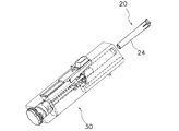
具体的には、ランセットデバイス10は、図1および図2に示すように、ランセット20と、本体30とを備えている。
ランセット20は、内部に穿刺傷を形成するためのステンレス製の穿刺針21(図4参照)を有しており、図2に示すように、本体30の先端側から取り付けられる。
本体30は、所定の穿刺方向へ突出させるための付勢力を穿刺針21(図4参照)に対して与えるコイルばね31(図6参照)と、コイルばね31によって発射された穿刺針21をハウジング35内に戻す戻しバネ(図示せず)とを内蔵している。Specifically, the
The
The
なお、これ以降の説明において使用される「先端側」とは、後述するランセット20の穿刺針21の先端が突出する側をいい、「後端側」とはその反対側をいうものとする。
[ランセット20の構成]
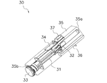
ランセット20は、図3に示すように、略円筒形状のケーシング22と、ランセットデバイス10を使用する際にケーシング22内で穿刺方向において先端側、後端側に移動可能な状態で収納される穿刺体23と、を備えている。なお、図3では、略円筒形状のケーシング22の内部の構成を説明する便宜上、ケーシング22の断面図を示している。Note that the “front end side” used in the following description refers to the side from which the front end of a
[Configuration of lancet 20]
As shown in FIG. 3, the
穿刺体23は、皮膚に穿刺傷を形成するための穿刺針21とともに樹脂によって一体成形されている(図4参照)。穿刺体23の樹脂成形部分には、テーパー部23a、フランジ部23b、溝23c、挿入部23dおよび溝23eが形成されている。テーパー部23a、フランジ部23b、溝23cは、穿刺針21が突出する先端側に形成されている。
テーパー部23aは、後端側に向かって細くなる部材であって、図9(a)および図9(b)に示すように、穿刺方向に直交する断面が楕円形になっている。また、テーパー部23aは、穿刺方向に対して5〜30度の範囲で設定された傾斜角度を有している。この下限値(5度)は、これよりも傾斜角度が小さくなると穿刺体23の長手方向の寸法が大きくなってしまうこと、径方向における寸法誤差によって穿刺体23とケーシング22とが嵌合する位置が大きく変動してしまうこと等から設定されている。一方、上限値(30度)は、これよりも傾斜角度を大きくすると、穿刺体23をケーシング22に嵌合させる際に必要なエネルギーが大きくなって操作性が低下してしまうことから設定されている。The
The
フランジ部23bは、穿刺体23の最も先端側に形成された円板状の部材であって、円板の中心部分から穿刺針21が突出している。
溝23cは、テーパー部23aとフランジ部23bとに挟まれるように形成された凹みである。使用後には、穿刺体23をケーシング22に対して相対的に後端側へ移動させ、この溝23cに後述するケーシング22の凸部22bを嵌合させて、穿刺体23をケーシング22の内部で保持することができる(図8参照)。The
The
挿入部23dは、後述する本体30の穿刺体ホルダ32に対して挿入される。このとき、穿刺体ホルダ32の先端部分が弾性変形して最先端部に形成された凸部32aが溝23eに嵌合する(図7(a)参照)。これにより、本体30において穿刺体ホルダ32の後端側に配置されたコイルばね31の弾性力によって、穿刺体23を穿刺体ホルダ32ごと穿刺方向に進出、退避させることができる。
The
そして、穿刺針21には、図3および図4に示すように、先端部分を覆うようにキャップ24が取り付けられており、使用前に穿刺針21の針先が露出しないようになっている。キャップ24は、穿刺体23と同様に穿刺針21とともに一体成形され、穿刺体23のフランジ部23bと一部がつながっている。このため、使用時には、キャップ24をねじりながら引き抜くことで、図4に示すように、キャップ24とフランジ部23bとの接続部分が分断されて、ケーシング22内で穿刺針21を露出させることができる。また、キャップ24は、突起部24aと、蓋部24bと、穴24cを有している。突起部24aは、穿刺方向に交差する方向に突出する部分であって、図3に示すように、キャップ24がケーシング22に装着されている状態では、後述するケーシング22の先端側の端部に形成された溝22cに嵌合する。これにより、使用前における穿刺体23をケーシング22の内部で保持することができる。蓋部24bは、使用前にケーシング22の最先端部分を覆う蓋として機能する。穴24cは、穿刺針21、穿刺体23、キャップ24を一体成形する際に、穿刺針21の先端側に密着して形成される穴であって、キャップ24が穿刺体23から分離されるまでの間、穿刺針21が挿入されている。
As shown in FIGS. 3 and 4, a
ケーシング22は、略円筒形状の部材であって、使用前から使用後に廃棄されるまでの間、穿刺体23を内部に収納している。また、ケーシング22は、図5に示すように、内周面22aと、凸部22bと、溝22cとを有している。内周面22aは、穿刺体23のテーパー部23aやフランジ部23b等の半径よりも若干大きい半径で形成されており、使用時には穿刺体23が穿刺方向において先端側、後端側へ移動する。凸部22bは、ケーシング22の内周面22aから内側へ突出する部材であって、ケーシング22の長さ方向における中心部付近に形成されている。使用後にランセット20を廃棄する際には、穿刺体23を後端側へ退避させ、図8に示すように、溝23cをこの凸部22bへ嵌合させる。これにより、使用後に穿刺針21がケーシング22の先端から突出することを回避することができるため、使用後の安全性を確保することができる。溝22cは、ケーシング22の先端側の内周面22aに形成された凹みである。使用前には、キャップ24の突起部24aがこの溝22cに嵌合しているため、穿刺体23が穿刺方向において先端側、後端側に移動しないようにケーシング22内で保持することができる。
The
[本体30の構成]
本体30は、図6に示すように、コイルばね31と、穿刺体ホルダ32と、回転体33と、付勢部34と、透明なハウジング35と、離脱部(嵌合解除機構)36と、セット解除ボタン37とを有しており、その先端側から上述したランセット20が取り付けられる(図2参照)。[Configuration of Main Body 30]
As shown in FIG. 6, the
コイルばね31は、ランセット20の穿刺体23を穿刺方向へ先進させるための付勢力を付与する部材であって、穿刺体ホルダ32の後端側に配置されている。
穿刺体ホルダ32は、ハウジング35の先端に形成された穿刺口35aから挿入されたランセット20の後端側の部分(挿入部23d、溝23e)を保持する。また、穿刺体ホルダ32は、先端側の端部に、穿刺体23の溝23eに嵌合する凸部(突起部)32aを有している。凸部32aは、穿刺体23の挿入部23dが挿入されると凸部32aの付近が弾性変形することで穿刺体23の後端側に形成された溝23eに嵌合する(図7(a)参照)。また、穿刺体ホルダ32の凸部32aと穿刺体23の後端側の溝23eとの嵌合は、上述したキャップ24の突起部24aとケーシング22の溝22cとの嵌合よりも嵌合力が大きい。このため、ランセット20を本体30へ取り付けた状態から、キャップ24を除去した場合でも、キャップ24とケーシング22との嵌合のほうが嵌合力が小さいため、穿刺体ホルダ32と穿刺体23との嵌合よりも先に嵌合が解除される。この結果、キャップ24をケーシング22から捻り切るために先端側へキャップ24を引き抜いた場合でも、穿刺体23と穿刺体ホルダ32との嵌合が外れることなく、キャップ24をケーシング22から取り外すことができる。回転体33は、外部に露出したダイヤル部分を回転させることで、軸方向を中心とする円周方向に回転する。回転体33は、ダイヤル部分の先端側における円筒部の内面に螺旋状に形成されたリブを有している。穿刺体ホルダ32の図示しない後端側の端部に形成された凸部は、穿刺体ホルダ32がバネの弾性力によって先端側へ付勢されることでリブと当接して移動量が規制される。このため、回転体33を回転させることにより、凸部とリブとの当接位置を変化させることができ、これにより穿刺体ホルダ32の移動量を調整することができる。よって、穿刺体23を穿刺方向における位置を前後に調整することができ、皮膚に対して穿刺を行う前には回転体33を回転させることで、穿刺針21の突出量を調整し、穿刺深さをコントロールすることが可能になる。The
The
付勢部34は、穿刺体23を穿刺方向へ発射させる際に、コイルばね31を縮めて穿刺体23を発射するための部材であって、ハウジング35の側面から露出している。
ハウジング35は、上述したコイルばね31、穿刺体ホルダ32等を内蔵しており、ランセットデバイス10の外郭を構成する。また、ハウジング35は、先端側の端部に穿刺口35a、後端側の端部に回転体33が収納される開口35bを有している。穿刺口35aは、ランセット20が挿入されるとともに、穿刺を行う際には穿刺針21の針の先端が飛び出す。開口35bは、回転体33の形状に合わせて円形に形成されている。The urging
The
離脱部36は、略直方体形状のハウジング35における付勢部34が露出する面の反対側の面に露出しており、ハウジング35の内部ではケーシング22の後端側の端部と接触するように配置されている。穿刺終了後には、図12に示すように、離脱部36を先端側へ移動させると、まず、挿入部36aと当接するケーシング22だけが先端側へ前進するため(図中矢印方向参照)、ケーシング22の凸部22bと穿刺体23の溝23cとが嵌合する。そして、さらに離脱部36を前進させると、離脱部36の一部である解除部36bが穿刺体ホルダ32の凸部32aの部分を押し上げることで、穿刺体23(挿入部23d、溝23e)の保持が解除され、本体30からランセット20が取り外される。
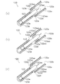
The
より詳細には、ランセット20を本体30から離脱させる前の段階においては、ランセット20のケーシング22が穿刺体23よりも先に先端側へ押し出されることで、穿刺体23はケーシング22に対して相対的に後端側へ移動する。ランセット20の内部においては、穿刺体23の中央部付近に形成されたテーパー部23aがケーシング22の内周面22aに形成されている凸部22bに乗り上げながら移動する。このため、ケーシング22の内周面22aに形成された凸部22b付近が弾性変形してテーパー部23aはさらに後端側へ移動し、凸部22bが穿刺体23の溝23cに嵌合したところで穿刺体23はケーシング22内で保持される。このとき、テーパー部23aは後端側のほうが細いため、穿刺体23をスムーズに嵌合位置まで移動させることができる。
More specifically, before the
なお、この穿刺後におけるケーシング22の凸部22bと穿刺体23の溝23cとの嵌合は、上述した穿刺体23の後端側の溝23eと穿刺体ホルダ32の凸部32aとの嵌合解除よりも先に行われる。そして、凸部22bと溝23cとの嵌合は、後端側の溝23eと凸部32aとの嵌合よりも嵌合力が大きく、一度嵌合すると解除することが困難になる程の嵌合力を有する。このため、ランセット20を本体30から離脱させる際には、2つの嵌合のうち、嵌合力の小さい嵌合(穿刺体ホルダ32の凸部32aと穿刺体23の溝23eとの嵌合)が先に解除され、ランセット20を本体30から離脱させることができる。さらに、穿刺体23の溝23cとケーシング22の凸部22bとが嵌合した状態では、穿刺体23の穿刺針21の先端はケーシング22の先端側の端部から露出しない。このため、穿刺した後の穿刺針21の先端が、ランセット20を本体30から取り外した後でケーシング22の先端から飛び出して使用者が怪我をしたり、使用済みの穿刺針21の先端に付着した体液によって病気に感染したりする危険を回避することができる。さらに、一度本体30から取り外されたランセット20は、ケーシング22内で穿刺体23を保持するように互いに嵌合している。このため、従来のランセットと比較して再使用することが困難な状態にすることができる。
After the puncture, the
[ランセットデバイス10の動作説明]
本実施形態のランセットデバイス10は、使用を開始する際にはまず、図2に示すように、使用されていない新しいランセット20を本体30の穿刺口35a(図6参照)へ挿入する。ランセット20を穿刺口35aの奥まで挿入していくと、図3に示す穿刺体23の後端側の端部に形成された挿入部23dが、穿刺体ホルダ32の凸部32aの部分を通過して奥まで挿入される。そして、図7(a)に示すように、挿入部23dに隣接するように形成された溝23eが穿刺体ホルダ32の凸部32aと嵌合することで、ランセット20の本体30への装着が完了するとともにコッキングされて穿刺針21の発射準備状態となる。[Description of operation of lancet device 10]
When starting to use the
次に、穿刺針21を露出させるために、図4に示すように、穿刺体23と一体成形されたキャップ24が取り除かれる。キャップ24は、穿刺体23のフランジ部23bの先端側の面と一部分が接続されているため、キャップ24を回転させてこの接続部分を捻り切るようにしてキャップ24を取り外す。このとき、取り外されるキャップ24には先端側へ引き抜く力が働くため、キャップ24と一部分が接続されている穿刺体23にも先端側へ引き抜く力が働く。しかし、キャップ24を取り外す時には、図7(a)に示すように、穿刺体23の後端側の端部が穿刺体ホルダ32によって保持されている。そして、この穿刺体23と穿刺体ホルダ32との嵌合力は、キャップ24とケーシング22との嵌合力あるいはキャップ24を穿刺体23から離脱させるために必要な力よりも大きい。この結果、キャップ24をケーシング22から取り外しても、穿刺体23がキャップ24とともに引き抜かれることはなく、ケーシング22内で保持される。このように、穿刺体23(キャップ24)の穿刺前の段階におけるケーシング22との嵌合位置と、穿刺後(廃棄時)の段階におけるケーシング22との嵌合位置とを別々に設けることで、穿刺体23をケーシング22内において1箇所の嵌合のみで保持する場合と比較して、穿刺動作をスムーズに行うことができる。
Next, in order to expose the
なお、一度穿刺した穿刺体23を再度発射する場合には、付勢部34によってコッキングしてコイルばね31を縮めて付勢力を付与した状態で付勢解除ボタン37によってコッキングを解除すればよい。
次に、穿刺を行う皮膚に対して穿刺口35aを当接させた状態でセット解除ボタン37を押してセットを解除すると、穿刺針21が、本体30の最先端側に形成された穿刺口35aから所定量だけ先端部分を突出する。そして、穿刺針21は、穿刺直後には図示しない戻しバネのばね力によって再びケーシング22内に戻される。なお、穿刺前後における穿刺針21の可動範囲は、図4に示す発射前の穿刺体23の待機位置と、穿刺針21の先端を数mm突出させる穿刺位置との間となる。When the
Next, when the set
穿刺終了後、ランセット20は、離脱部36によって本体30から取り外されて廃棄される。ランセット20の本体30からの取り外しは、図6に示す離脱部36によって行われる。すなわち、離脱部36を先端側へ移動させることで、穿刺体ホルダ32による穿刺体23の保持が解除され、ランセット20を穿刺口35aから取り出すことができる。具体的には、離脱部36を先端側へ移動させると、まず、ケーシング22だけが先端側へ移動する。このため、穿刺体ホルダ32によって保持されている穿刺体23は、ケーシング22に対して相対的に後端側へと移動する。このとき、穿刺体23の中央部付近に形成されたテーパー部23aが、ケーシング22の内周面22aに形成された凸部22bの部分を押し広げながら移動し、ケーシング22の凸部22bが穿刺体23の溝23cに嵌合する。この嵌合は、嵌合力が強いため、ランセット20を本体30から取り外した後でケーシング22の先端側から穿刺針21の先端部分が突出することを防止することができる。これにより、使用前の状態では、キャップ24によって穿刺針21の突出を防止し、使用後には、嵌合力の大きい嵌合によってケーシング22内に穿刺体23を保持することで、使用前後における危険を回避することができる。
After the puncturing is completed, the
ケーシング22の凸部22bが穿刺体23の溝23cに嵌合した後には、図7(a)に示す穿刺体ホルダ32による穿刺体23の保持が解除される。つまり、凸部22bと溝23cとの嵌合力が、穿刺体ホルダ32の凸部32aと穿刺体23の溝23eとの嵌合力よりも大きいため、先に穿刺体ホルダ32による穿刺体23の保持が解除される。このように、ケーシング22内における凸部22bと穿刺体23の溝23cとの嵌合は、テーパー部23aの形状、凸部22bや内周面22aの弾性変形等を利用することで、嵌合し易く抜けにくくすることができる。
After the
以上のような手順により、使用済のランセット20は本体30から取り外され、廃棄される。しかし、取り外されたランセット20では、穿刺体23がケーシング22内で強固な嵌合力により保持されているため、穿刺針21の先端がケーシング22から突出して怪我をしたり、穿刺針21に付着した体液等によって病気が感染したりすることを確実に防止することができる。さらに、一度本体30から取り外されたランセット20は、ケーシング22内で穿刺体23を保持するように互いに嵌合している。このため、従来のランセットと比較して再使用することが困難な状態にすることができる。
By the procedure as described above, the used
[本ランセットデバイス10の特徴]
(1)
本実施形態のランセットデバイス10が備えているランセット20は、図3に示すように、ケーシング22と、ケーシング22内で穿刺方向へ移動可能な状態で収納された穿刺体23と、を有している。そして、ランセット20を本体30から取り外す際に、ケーシング22内において穿刺体23を穿刺方向へ移動不能な状態で保持する嵌合を形成する凸部22bをケーシング22の内周面22aに、凹部(溝23c)を穿刺体23に形成している。[Features of the present lancet device 10]
(1)
The
これにより、ランセット20を本体30から取り外した後には、図8に示すように、ケーシング22内において穿刺体23を穿刺方向へ移動不能な状態で保持することができる。このとき、穿刺体23は、穿刺針21の先端がケーシング22の先端側の端部からは突き出ない位置で保持される。このため、使用後にはランセットの先端にキャップを取り付けたり、簡易な嵌合により穿刺針の突出を抑制する従来のランセットと比較して、ランセット20を廃棄する際に使用者が怪我をしたり、穿刺針21の先端に付着した体液等によって病気が感染したりする危険を確実に回避することができる。さらに、一度本体30から取り外されたランセット20は、ケーシング22内で穿刺体23を保持するように互いに嵌合している。このため、従来のランセットと比較して再使用することが困難な状態にすることができる。
Thereby, after removing the
(2)
本実施形態のランセット20では、ランセット20を本体30から取り外した後、図8に示すように、穿刺体23をケーシング22内で保持する第1嵌合部を形成する穿刺体23の溝23cとケーシング22の凸部22bとは、一度嵌合すると抜けにくい強固な嵌合力を有している。(2)
In the
これにより、使用後のランセット20において穿刺体23がケーシング22内において穿刺方向への移動を禁止されるため、穿刺した後で使用済のランセット20を廃棄する際等において、ランセット20の先端から穿刺針21が突出することによる使用者の怪我や病気の感染の危険性を確実に回避することができる。
(3)
本実施形態のランセット20では、使用後に穿刺体23とケーシング22とを嵌合させるために、図9(a)および図9(b)に示すように、溝23cと凸部22bとを組み合わせて第1嵌合部を構成している。そして、穿刺体23には、この溝23cに隣接して形成されたテーパー部23aが穿刺方向に直交する断面が楕円形状となっており、円形のケーシング22の内周面22aに形成された凸部22bと2点で接触した状態で保持される。Accordingly, since the
(3)
In the
このように、断面が楕円形状のテーパー部23aを用いてケーシング22内に嵌合させることで、ケーシング22の内周面22aを弾性変形させながら嵌合させ易くすることができる。
(4)
本実施形態のランセット20では、穿刺体23のケーシング22内における穿刺方向への移動を禁止する第1嵌合部(溝23c、凸部22b)は、穿刺体23が穿刺方向へ発射される際に待機している位置よりも後端側で穿刺体23を保持する。つまり、ランセット20では、使用前から使用時までは穿刺体23のテーパー部23aがケーシング22の内周面22aに形成された凸部22bよりも先端側において自由に移動しながら穿刺を行う。一方、穿刺終了後、ランセット20が本体30から取り外された後では、穿刺体23をケーシング22に対して相対的に後端側へ移動させることで、穿刺体23の溝23cが凸部22bに嵌合して、穿刺体23が穿刺方向において移動不能な状態で保持される。Thus, it is possible to easily fit the inner
(4)
In the
これにより、使用後における安全性を確保したランセット20を提供することができる。
(5)
本実施形態のランセット20では、使用後におけるケーシング22内における穿刺体23の穿刺方向への移動を禁止する第1嵌合部を、図8に示すように、穿刺体23に形成された溝23cと、ケーシング22の内周面22aに形成された凸部22bとで構成している。Thereby, the
(5)
In the
これにより、1組の凹部と凸部とを組み合わせた簡易な構成であっても嵌合力の強い第1嵌合部を容易に構成することができる。
(6)
本実施形態のランセット20では、図8に示すように、穿刺体23の溝23cにケーシング22の内周面22aに形成された凸部22bが嵌合する際には、凸部22bの周辺が弾性変形する。Thereby, even if it is a simple structure which combined one set of recessed part and convex part, the 1st fitting part with strong fitting force can be comprised easily.
(6)
In the
このように、弾性変形を利用して第1嵌合部を形成することで、嵌合し易く抜けにくい嵌合を構成することができる。
(7)
本実施形態のランセット20では、穿刺体23が、図4に示すように、第1嵌合部を構成する穿刺体23の溝23cの後端側に、後端側になるにつれて細くなるテーパー部23aを有している。Thus, by forming the first fitting portion using elastic deformation, it is possible to configure a fitting that is easy to fit and difficult to come off.
(7)
In the
このように、テーパー部23aの細い側からケーシング22の内周面22aに形成された凸部22bに挿入していくことで、嵌合し易く抜けにくい強固な嵌合力を得ることができる。
(8)
本実施形態のランセット20では、使用前の段階でケーシング22内で穿刺体23を保持する第2嵌合部を、図3に示すように、キャップ24に形成された突起部24aと、ケーシング22の内周面22aにおける最先端側に形成された溝22cと、で構成している。Thus, by inserting into the
(8)
In the
これにより、使用前にはキャップ24によって穿刺針21の先端を覆った状態とし、かつ穿刺針21を覆うキャップ24をケーシング22内に仮止めしておくことができる。よって、使用する際にはキャップ24を捻り切るようにして穿刺体23との接続を解除することで、容易に使用可能な状態とすることができるとともに、使用前における穿刺針21による怪我の発生を防止することができる。
Thereby, the
(9)
本実施形態のランセット20では、使用前に穿刺針21の先端が露出しないように穿刺針21を覆うキャップ24は、図3に示すように、穿刺体23とともに一体成形されている。
これにより、穿刺体23の一部として形成することで、部品点数を削減してコストダウンを図ることができる。(9)
In the
Thereby, by forming as a part of
(10)
本実施形態のランセットデバイス10では、図3および図7(a)に示すように、ランセット20を本体30に取り付けた際に、穿刺体23を後端側から保持する第3嵌合部(溝23e、凸部32a)を有している。
これにより、コイルばね31によって付勢力を穿刺体ホルダ32に対して付与することで、穿刺体23を穿刺体ホルダ32ごと穿刺方向へ発射させることができる。また、穿刺体23が穿刺方向へ抜けないように保持することで、安全性の高いランセットデバイス10を得ることができる。さらに、使用後には、この第3嵌合部を解除して第1嵌合部(溝23c、凸部22b)で穿刺体23をケーシング22内で保持することで、使用後の安全性を確保することができる。(10)
In the
Thereby, the
(11)
本実施形態のランセットデバイス10では、第3嵌合部(溝23e、凸部32a)の嵌合力は、第1嵌合部(溝23c、凸部22b)の嵌合力よりも小さい。
これにより、使用後にランセット20を本体30から取り外す際には、嵌合力の小さい第3嵌合部から優先的に嵌合が解除される。この結果、第1嵌合部が第3嵌合部よりも先に嵌合が解除され、ランセット20を本体30から取り外した状態において穿刺体23がケーシング22内で移動可能な状態となることを防止することができる。(11)
In the
Thereby, when removing the
(12)
本実施形態のランセットデバイス10では、第3嵌合部(溝23e、凸部32a)の嵌合力は、第2嵌合部(溝22c、突起部24a)の嵌合力よりも大きい。
これにより、使用する際に、ランセット20の先端を覆うキャップ24を捻り切るようにして穿刺体23から離脱させる場合でも、穿刺体ホルダ32から穿刺体23が外れないようにしっかり穿刺体ホルダ32内で保持することができる。(12)
In the
Thus, when the
(13)
本実施形態のランセットデバイス10では、図3および図7(a)に示すように、第3嵌合部を、穿刺体23に形成された溝23eと、穿刺体ホルダ32の先端部に形成された凸部32aとで構成している。
これにより、簡易な構成であっても、穿刺体23と穿刺体ホルダ32との間に必要な嵌合力を得ることができるとともに、嵌合し易くて抜けにくい嵌合を構成することができる。(13)
In the
Thereby, even if it is a simple structure, while being able to obtain required fitting force between the
(14)
本実施形態のランセットデバイス10では、第3嵌合部を構成する凸部32aは、図7(a)に示すように、穿刺方向に交差する方向に弾性を有する弾性部32bの先端に形成されている。
これにより、穿刺体ホルダ32の一部が弾性変形することで、その先端に形成された凸部32aを容易に穿刺体23の後端側の溝23eに嵌合させることができる。(14)
In the
Thereby, a part of the
(15)
本実施形態のランセットデバイス10では、図3等に示すように、第3嵌合部を構成する穿刺体23に形成された溝23eに隣接する後端側の端部に、後端側に向かうにつれて細くなる挿入部23dを有している。
これにより、挿入部23dの細い側から穿刺体ホルダ32に挿入し、容易に溝23eに凸部32aを嵌合させることができる。この結果、嵌合させ易く抜けにくい嵌合を得ることができる。(15)
In the
Thereby, it can insert in the
(16)
本実施形態のランセットデバイス10では、図12に示すように、離脱部36を穿刺方向において先端側へ前進させることで、ケーシング22内において穿刺体23を保持させるとともに、穿刺体23と穿刺体ホルダ32との嵌合を解除してランセット20ごと本体30から取り外す。(16)
In the
これにより、穿刺後には、離脱部36を前進させるだけで容易にランセット20を廃棄することができる。さらに、このときランセット20では、ケーシング22内に穿刺体23が保持された状態となるため、使用後における安全性を確保した状態でランセット20を廃棄することができる。
[他の実施形態]
以上、本発明の一実施形態について説明したが、本発明は上記実施形態に限定されるものではなく、発明の要旨を逸脱しない範囲で種々の変更が可能である。Thereby, after puncturing, the
[Other Embodiments]
As mentioned above, although one Embodiment of this invention was described, this invention is not limited to the said embodiment, A various change is possible in the range which does not deviate from the summary of invention.
(A)
上記実施形態では、各嵌合部の構成についてそれぞれ説明したが、嵌合部の構成は上記実施形態において説明した構成に限定されるものではない。
例えば、凸部と凹部とが反対に形成されていてもよいし、凸部と凹部とを組み合わせた単純な嵌合ではなく、部材の弾性変形を利用した嵌合を用いてもよい。(A)
In the said embodiment, although the structure of each fitting part was each demonstrated, the structure of a fitting part is not limited to the structure demonstrated in the said embodiment.
For example, the convex portion and the concave portion may be formed opposite to each other, or not a simple fitting combining the convex portion and the concave portion, but a fitting utilizing elastic deformation of the member may be used.
ただし、上記実施形態のように、凸部と凹部とを組み合わせ、かつ弾性変形を利用した嵌合を形成することは、単純な構成であっても嵌合し易く抜けにくい嵌合を形成することができる点で好ましい。
(B)
上記実施形態では、図9(a)、図9(b)に示すように、穿刺体23に断面形状が楕円形の長辺側に突出したテーパー部23aに隣接して溝23cが形成され、ケーシング22には断面形状が円形の内周部に沿って凸部22bが形成されており、これらが嵌合して第1嵌合部を構成する例を挙げて説明した。しかし、第1嵌合部の構成はこれに限定されるものではない。However, as in the above-described embodiment, combining the convex portion and the concave portion and forming a fitting utilizing elastic deformation forms a fitting that is easy to fit and difficult to come off even with a simple configuration. It is preferable at the point which can do.
(B)
In the above embodiment, as shown in FIGS. 9 (a) and 9 (b), the
例えば、図10(a)および図10(b)に示すように、断面形状が円形の穿刺体23から放射状に延びる複数のリブ23gを用いて、ケーシング22の内周側に形成された溝22cに嵌合する構成であってもよい。この場合でも、断面形状が楕円形の長辺側を突出部として使用する場合と同様に、ケーシング22内で2点保持されることができる。
(C)
上記実施形態では、第3嵌合部(溝23e、凸部32a)として、図7(a)に示すような凸部32aに隣接する弾性部32bの弾性変形を利用した嵌合を例に挙げて説明した。しかし、本発明はこれに限定されるものではない。For example, as shown in FIG. 10A and FIG. 10B, a
(C)
In the above embodiment, the third fitting portion (
例えば、図7(b)に示すように、穿刺体ホルダ32の片側に形成された凸部32aが弾性部32bの弾性変形によって溝23eに嵌合する構成であってもよい。
(D)
上記実施形態では、穿刺針21を発射させる機構としてばね力を利用した例を挙げて説明した。しかし、本発明はこれに限定されるものではない。For example, as shown in FIG. 7 (b), a configuration may be adopted in which a
(D)
In the said embodiment, the example using a spring force was given and demonstrated as a mechanism in which the
例えば、ばね力に限らず、電磁力やエア力を利用したものであってもよい。
(E)
上記実施形態では、穿刺体23にテーパー部23a、ケーシング22の円筒部22aの内面に上記テーパー部23aに隣接するように形成された溝23cと嵌合する凸部22bを形成した例を挙げて説明した。しかし、本発明はこれに限定されるものではない。For example, not only spring force but also electromagnetic force or air force may be used.
(E)
In the said embodiment, the
例えば、穿刺体23側ではなく、図11(a)および図11(b)に示すように、ケーシング22の円筒部22a側に第1テーパー部22d、第2テーパー部22eを形成し、この第1テーパー部22dと第2テーパー部22eとの間の溝部分に穿刺体23に形成されたフランジ部23hが嵌合して第1嵌合部を形成してもよい。
(F)
上記実施形態では、各嵌合部を形成する凸部と凹部とが互いに嵌合する部材にそれぞれ形成されている例を挙げて説明した。しかし、本発明はこれに限定されるものではない。For example, the
(F)
In the said embodiment, the convex part and recessed part which form each fitting part were each demonstrated and demonstrated to the member which mutually fits, and was demonstrated. However, the present invention is not limited to this.
例えば、凸部と凹部とが形成されている部材が反対であってもよい。
(G)
上記実施形態では、穿刺傷を形成するためのランセット20およびランセットデバイス10に対して本発明を適用した例を挙げて説明した。しかし、本発明はこれに限定されるものではない。For example, the member in which the convex part and the recessed part are formed may be opposite.
(G)
In the said embodiment, the example which applied this invention with respect to the
例えば、図13に示すように、ケーシング22の先端側の端部に、穿刺傷から流出する血液を検知するバイオセンサ51が取り付けられているランセット50に対して本発明を適用することもできる。このバイオセンサ52は、穿刺傷から流出する血液を吸入口51aから取り込み、試薬部51bにおいて試薬と反応させた後、図示しない測定装置と接続されている端子51cから測定装置に対してバイオセンサ51における測定結果が送信される。これによれば、穿刺したままの状態でバイオセンサ51に付着した血液からグルコース濃度を測定することができる。
For example, as shown in FIG. 13, the present invention can be applied to a
(H)
上記実施形態では、穿刺後におけるケーシング22と穿刺体23との嵌合を、ケーシング22の内周面側に形成された第1テーパー部22dと穿刺体23の外周面に形成された溝23cとを組み合わせて行う例を挙げて説明した。しかし、本発明はこれに限定されるものではない。(H)
In the above-described embodiment, the fitting between the
例えば、図14に示すようなキャップ24および穿刺体123と、図15に示すケーシング(ケース部)122とを組み合わせて、ランセット120(穿刺体123)とケーシング122とを嵌合させてもよい。つまり、図14に示す穿刺体123の外周部の両脇において左右対称に形成された弾性アーム部材(弾性部材、第1・第2嵌合部)123aの先端部123aaが、図15に示すケーシング122の円筒部122aの内周側に形成された先端開口122bから挿入され、円筒部122aの内側に形成される嵌合部122cに形成された開口(凹部、第1・第2嵌合部)122dに嵌合することで、ケーシング122内で穿刺体123が移動しないように保持することができる。また、箱詰めされた状態での搬送中や、穿刺後等において、誤って弾性アーム部材123aに接触してケーシング122内において穿刺体123を保持する嵌合が外れてしまうことを防止することができる。
For example, the
ここで、具体的な嵌合方法について図16(a)〜図16(c)を用いて説明すれば以下の通りである。
まず、使用前には、図16(a)に示すように、穿刺体123は、ケーシング122の先端開口122b側から挿入され、本体部122aよりも後方に形成された開口122dに弾性アーム部材123aが嵌合した状態で保持されている。このとき、弾性アーム部材123aの先端部123aaが本体部122aの凸部122aaに係止されて穿刺方向に移動不能となっている。Here, a specific fitting method will be described with reference to FIGS. 16A to 16C.
First, before use, as shown in FIG. 16A, the
次に、付勢部材を含む本体側への装着時には、穿刺体123を穿刺方向に挿入していくと本体の一部が弾性アーム部材123aの先端部123aaに接触して弾性アーム部材123aが内周側へと押圧されて弾性変形する。すると、図16(b)に示すように、ケーシング122の開口122dと穿刺体123の弾性アーム部材123aとの嵌合が解除され、そのまま穿刺体123をケーシング122に対して穿刺方向において前方へ相対移動させると、弾性アーム部材123aの先端部123aaが本体部122aの後端に形成された凸部122aaよりも先端側へ移動する。これにより、穿刺体123をケーシング122内で移動可能な状態とすることができるため、穿刺体123の挿入部123dおよび段差123eの部分が嵌合した図示しない本体側のランセットホルダを付勢部材によって穿刺方向前方へ付勢することで、穿刺を行うことができる。
Next, when the
そして、穿刺後には、図16(b)に示す状態から穿刺体123をケーシング122に対して穿刺方向において後方へ相対移動させると、弾性アーム部材123aの先端部123aaがケーシング122の本体部122aの凸部122aaに乗り上げて内周側へ弾性変形する。すると、図16(c)に示すように、ケーシング122の開口122dに弾性アーム部材123aが嵌合する。このとき、弾性アーム部材123aの先端部123aaがケーシング122の本体部122aの後端部の凸部122aaによって係止され、穿刺体123がケーシング122内における穿刺方向において移動不能となる。
After the puncture, when the
以上のように、穿刺体123の弾性アーム部材123aを穿刺方向に交差する方向、つまり内周側へ弾性変形させてケーシング122の開口122dに嵌合、その解除を行うことで、容易に穿刺体123の保持、解除を行うことができる。
なお、図19に示すケーシング222のように、外壁部222eを設けてもよい。この場合には、箱詰めされた状態での搬送中や、穿刺後等において、誤って弾性アーム部材223aに接触してケーシング222の円筒部222a内において、穿刺体223を保持するための嵌合が外れてしまうことを防止することができる。なお、図19に示す例では、穿刺体223のつば部分223bと弾性アーム部材223aの間にケーシング222の凸部222fを挟み込むようにして嵌合させている。As described above, the
In addition, you may provide the
(I)
上記実施形態では、穿刺後におけるケーシング22と穿刺体23との嵌合を、ケーシング22の内周面側に形成された第1テーパー部22dと穿刺体23の外周面に形成された溝23cとを組み合わせて行う例を挙げて説明した。しかし、本発明はこれに限定されるものではない。(I)
In the above-described embodiment, the fitting between the
例えば、図18に示すように穿刺方向に交差する方向に弾性変形するケーシング222の弾性部材(第1嵌合部)222bを、穿刺体223(図17(a)等参照)の一部に嵌合させるランセット220(図17(a)等参照)であってもよい。
ここで、具体的な嵌合方法について、図17(a)〜図17(c)を用いて説明すれば以下の通りである。For example, as shown in FIG. 18, an elastic member (first fitting portion) 222b of the
Here, a specific fitting method will be described with reference to FIGS. 17 (a) to 17 (c).
まず、穿刺前のランセット220は、図17(a)に示すように、穿刺体223はキャップ224の凸部(第2嵌合部)224aとケーシング222の内周面に形成された溝(第2嵌合部)222cとの嵌合によってケーシング222内で保持されている。そして、図示しない本体側へランセット220を装着すると穿刺体223の後端の挿入部223dが本体側においてキャップ224とケーシング222との嵌合よりも強固に保持され、穿刺体223の保持が解除されることはなく、使用開始時にはキャップ224を取り外すことができる。
First, in the
次に、穿刺時には、図17(b)に示すように、穿刺体223はケーシング222に対して嵌合していない状態であるため、本体側からの付勢力を受けて穿刺方向前方に向かって移動して穿刺を行うことができる。このとき、穿刺体223は、後端の挿入部223dが本体側のランセットホルダに保持されているため、ケーシング222の先端から不意に穿刺針221が突出することはない。
Next, at the time of puncturing, as shown in FIG. 17B, since the
そして、穿刺後には、図示しない本体側の離脱部を穿刺方向前方へ移動させることで、ケーシング222を穿刺体223に対して穿刺方向前方へ相対移動させる。すると、図17(c)に示すように、ケーシング222の内周に形成された弾性部材222bが穿刺方向に交差する方向に弾性変形しながら穿刺体223のテーパー部223aを乗り越えて溝(第1嵌合部)223cに嵌合する。このとき、穿刺体223の先端に形成されたフランジ部223bが、ケーシング222の弾性部材222bの穿刺方向前方側の端部に形成された凸部222dに係止される。これにより、穿刺体223をケーシング222内で穿刺方向において移動不能な状態で保持することができる。
After puncturing, the
本発明のランセットおよびランセットデバイスは、簡易な構成で、特に、使用後の安全性が高いという効果を奏することから、様々な分野において使用される穿刺器具に対して広く適用可能である。 The lancet and the lancet device of the present invention have a simple configuration, and in particular, have an effect of high safety after use. Therefore, the lancet and the lancet device are widely applicable to puncture instruments used in various fields.
Claims (30)
穿刺針と、前記穿刺針とは反対側の端部に形成されており前記本体部に連結される連結部と、を有する穿刺体と、
前記穿刺方向において前後に移動可能な状態で前記穿刺体を収納する筒状部と、前記穿刺針の突出側の前端部に形成された開口と、を有するケース部と、
前記穿刺体の前記連結部を前記本体部から分離した後、前記穿刺方向において前後に移動不能な状態で前記穿刺体を前記ケース部内で保持する第1嵌合部と、
使用前の前記穿刺体を前記穿刺方向において前後に移動不能に保持する第2嵌合部と、
を備えたランセット。A lancet attached to a main body provided with a biasing member for projecting the tip of a puncture needle in a predetermined puncture direction,
A puncture body having a puncture needle and a connecting portion formed at an end opposite to the puncture needle and connected to the main body portion;
A case portion having a cylindrical portion for accommodating and apertures formed in said front end portion of the protruding side of the puncture needle the puncture body in a movable state back and forth in the puncture direction,
A first fitting portion for holding the puncture body in the case portion in a state in which the connection portion of the puncture body is not movable back and forth in the puncture direction after separating the connecting portion of the puncture body;
A second fitting portion that holds the puncture body before use immovably back and forth in the puncture direction;
Lancet with
請求項1に記載のランセット。The second fitting portion includes a cap portion attached to the distal end side of the puncture body so as to cover the distal end of the puncture needle, and a convex portion and a concave portion formed on the inner surface of the cylindrical portion. Composed of
The lancet according to claim 1 .
請求項2に記載のランセット。The cap part is integrally formed with the puncture body,
The lancet according to claim 2 .
請求項1から3のいずれか1項に記載のランセット。The first fitting portion has a strong fitting force that prohibits the puncture needle from moving again in the puncture direction.
The lancet according to any one of claims 1 to 3 .
請求項1から4のいずれか1項に記載のランセット。The first fitting portion holds the puncture body on the connection side with the main body portion from the standby position of the puncture body immediately before firing so that the tip of the puncture needle protrudes from the opening.
The lancet according to any one of claims 1 to 4 .
請求項1から5のいずれか1項に記載のランセット。The first fitting portion is a combination of a convex portion and a concave portion formed on the outer peripheral surface of the puncture body substantially parallel to the puncture direction and the inner peripheral surface of the case portion to which the puncture body moves. Composed,
The lancet according to any one of claims 1 to 5 .
請求項6に記載のランセット。At least one of the convex portion and the concave portion is fitted to each other by elastic deformation,
The lancet according to claim 6 .
前記筒状部の内側の面に形成され、前記凹部と嵌合する凸部と、
を有している、
請求項1から7のいずれか1項に記載のランセット。The first fitting portion is formed in an outer peripheral portion of the puncture body, and is formed with a concave portion formed adjacent to a tapered projecting portion that narrows toward a connection side with the main body portion,
A convex portion that is formed on the inner surface of the cylindrical portion and fits into the concave portion;
have,
The lancet according to any one of claims 1 to 7 .
請求項1から7のいずれか1項に記載のランセット。It has a tapered part formed on either one of the outer peripheral part of the puncture body and the inner peripheral surface of the cylindrical part,
The lancet according to any one of claims 1 to 7 .
前記筒状部の内側の面に形成されたテーパー部に隣接して設けられており、前記凸部と嵌合する凹部と、
を有している、
請求項1から7のいずれか1項に記載のランセット。The first fitting portion includes a convex portion formed on an outer peripheral portion of the puncture body,
A concave portion that is provided adjacent to a tapered portion formed on the inner surface of the cylindrical portion, and that fits with the convex portion;
have,
The lancet according to any one of claims 1 to 7 .
前記筒状部の内側の円筒面に形成されており、前記凹部に嵌合する凸部と、
を有している、
請求項1から7のいずれか1項に記載のランセット。The first fitting portion is a recess formed so as to be adjacent to a plurality of protruding portions protruding in a direction intersecting the puncturing direction on the outer peripheral surface of the puncture body,
Formed on the inner cylindrical surface of the tubular portion, and a convex portion that fits into the concave portion;
have,
The lancet according to any one of claims 1 to 7 .
前記筒状部の内側の円筒面に形成されており、前記凸部に嵌合する凹部と、
を有している、
請求項1から7のいずれか1項に記載のランセット。The first fitting portion includes a plurality of convex portions protruding in a direction intersecting the puncturing direction on the outer peripheral surface of the puncture body,
Formed on the inner cylindrical surface of the cylindrical portion, and a recess fitted into the convex portion;
have,
The lancet according to any one of claims 1 to 7 .
請求項1から7のいずれか1項に記載のランセット。The first fitting portion includes a convex portion formed so as to protrude from an outer peripheral portion of the puncture body in a direction intersecting the puncture direction, and having a cross-sectional shape cut by a plane perpendicular to the puncture direction having an elliptical shape. Have
The lancet according to any one of claims 1 to 7 .
請求項1から13のいずれか1項に記載のランセット。An analysis tool attached to the front end of the case portion in the puncture direction, further comprising an analysis tool for analyzing a specific component in a body fluid collected from a puncture wound formed by the puncture needle;
The lancet according to any one of claims 1 to 13 .
前記ランセットが装着された状態において前記穿刺体の後端側を保持する穿刺体ホルダと、前記穿刺体を前記穿刺体ホルダごと穿刺方向へ発射させる付勢部材と、を有する本体部と、
前記穿刺体と前記穿刺体ホルダとを前記穿刺方向において保持する第3嵌合部と、
を備えた、
ランセットデバイス。The lancet according to any one of claims 1 to 14 ,
A main body having a puncture body holder that holds the rear end side of the puncture body in a state where the lancet is mounted, and a biasing member that fires the puncture body together with the puncture body holder in a puncture direction;
A third fitting portion for holding the puncture body and the puncture body holder in the puncture direction;
With
Lancet device.
請求項15に記載のランセットデバイス。The third fitting portion has a smaller fitting force for holding the puncture body than the first fitting portion,
The lancet device according to claim 15 .
前記第3嵌合部は、前記第2嵌合部と比較して嵌合力が大きい、
請求項15または16に記載のランセットデバイス。The lancet has a second fitting portion formed on the puncture body and a cap portion for covering the tip of the puncture needle in order to hold the puncture body in the case portion before use. ,
The third fitting portion has a larger fitting force than the second fitting portion,
The lancet device according to claim 15 or 16 .
前記本体部の前記穿刺体ホルダに形成された、前記溝部に嵌合する突起部と、
を有している、
請求項15から17のいずれか1項に記載のランセットデバイス。The third fitting portion includes a groove portion formed on an outer peripheral surface substantially parallel to the puncture direction of the puncture body,
A protrusion formed on the puncture body holder of the main body, and fitted into the groove;
have,
The lancet device according to any one of claims 15 to 17 .
請求項18に記載のランセットデバイス。The protrusion is formed at the tip of the puncture body holder via an elastic member having elasticity in a direction intersecting the puncture direction.
The lancet device according to claim 18 .
請求項18または19に記載のランセットデバイス。The puncture body further includes an insertion portion that is formed adjacent to a connection side of the groove portion with the main body portion and becomes narrower toward a connection side with the main body portion.
The lancet device according to claim 18 or 19 .
請求項15から20のいずれか1項に記載のランセットデバイス。A fitting release mechanism for releasing fitting in the third fitting portion;
The lancet device according to any one of claims 15 to 20 .
前記ケース部の内周部に形成されており前記弾性部材が嵌合する凹部と、によって構成されている、
請求項1に記載のランセット。A plurality of the first fitting portions are provided on the outer peripheral portion of the puncture body, and an elastic member that elastically deforms in a direction intersecting the puncture direction;
A recess formed in an inner peripheral portion of the case portion and fitted with the elastic member;
The lancet according to claim 1.
請求項22に記載のランセット。The first fitting portion also functions as a second fitting portion that holds the puncture body in the case portion before puncturing.
The lancet according to claim 22 .
請求項23に記載のランセット。When the puncture body is attached to the main body portion, the elastic member comes into contact with a part of the main body portion and elastically deforms in a direction crossing the puncture direction, and the puncture body is attached to the case portion. On the other hand, by relatively moving in the puncturing direction, the fitting between the elastic member and the recess is released.
The lancet according to claim 23 .
請求項22から24のいずれか1項に記載のランセット。When the puncture body is removed from the main body portion, the puncture body moves relative to the case portion in the puncture direction, so that the elastic member comes into contact with a part of the case portion and the puncture body Elastically deforming in a direction intersecting the direction, and the elastic member and the concave portion are fitted,
The lancet according to any one of claims 22 to 24 .
請求項1に記載のランセット。A plurality of the first fitting portions are provided on the outer peripheral portion of the puncture body, and are formed between an elastic member that is elastically deformed in a direction crossing the puncture direction and a collar portion formed at the tip of the puncture body. And a convex portion formed on the inner peripheral surface side of the case portion.
The lancet according to claim 1.
請求項22から26のいずれか1項に記載のランセット。The casing has a wall portion arranged to cover the elastic member of the puncture body,
The lancet according to any one of claims 22 to 26 .
請求項1に記載のランセット。The first fitting portion is configured by combining an elastic member that is formed in the case portion and elastically deforms in a direction intersecting the puncturing direction, and a concave portion formed in an outer peripheral portion of the puncture body. ,
The lancet according to claim 1.
請求項26に記載のランセット。The cross-sectional shape along the direction perpendicular to the puncture direction of the puncture body is circular,
The lancet according to claim 26 .
請求項28または29に記載のランセット。The puncture body is further formed with a tapered portion disposed so as to be adjacent to the concave portion,
A lancet according to claim 28 or 29 .
Priority Applications (1)
| Application Number | Priority Date | Filing Date | Title |
|---|---|---|---|
| JP2006543178A JP4969247B2 (en) | 2004-10-25 | 2005-10-25 | Lancet and lancet device equipped with the same |
Applications Claiming Priority (4)
| Application Number | Priority Date | Filing Date | Title |
|---|---|---|---|
| JP2004309050 | 2004-10-25 | ||
| JP2004309050 | 2004-10-25 | ||
| PCT/JP2005/019617 WO2006046570A1 (en) | 2004-10-25 | 2005-10-25 | Lancet and lancet device with the same |
| JP2006543178A JP4969247B2 (en) | 2004-10-25 | 2005-10-25 | Lancet and lancet device equipped with the same |
Publications (2)
| Publication Number | Publication Date |
|---|---|
| JPWO2006046570A1 JPWO2006046570A1 (en) | 2008-05-22 |
| JP4969247B2 true JP4969247B2 (en) | 2012-07-04 |
Family
ID=36227811
Family Applications (1)
| Application Number | Title | Priority Date | Filing Date |
|---|---|---|---|
| JP2006543178A Active JP4969247B2 (en) | 2004-10-25 | 2005-10-25 | Lancet and lancet device equipped with the same |
Country Status (5)
| Country | Link |
|---|---|
| US (1) | US8251919B2 (en) |
| EP (1) | EP1815792B1 (en) |
| JP (1) | JP4969247B2 (en) |
| CN (1) | CN100484472C (en) |
| WO (1) | WO2006046570A1 (en) |
Cited By (1)
| Publication number | Priority date | Publication date | Assignee | Title |
|---|---|---|---|---|
| KR20160092813A (en) * | 2015-01-28 | 2016-08-05 | (주)월드씨앤피 | Safety cap for needle |
Families Citing this family (17)
| Publication number | Priority date | Publication date | Assignee | Title |
|---|---|---|---|---|
| US20090198265A1 (en) * | 2005-04-28 | 2009-08-06 | Matsushita Electric Industrial Co., Ltd. | Puncture device and puncture needle cartridge |
| JP4820822B2 (en) * | 2005-07-29 | 2011-11-24 | アークレイ株式会社 | Puncture device |
| KR20080033342A (en) * | 2005-08-10 | 2008-04-16 | 이즈미 가부시키가이샤 | Needle insertion device, and lancet assembly and injector assembly that form the same |
| MX2008010539A (en) | 2006-02-20 | 2009-01-22 | Asahi Polyslider Co Ltd | Lancet. |
| CN101400302B (en) * | 2006-03-10 | 2010-11-03 | 爱科来株式会社 | Lancet device |
| JPWO2007114101A1 (en) * | 2006-04-03 | 2009-08-13 | 泉株式会社 | Lancet assembly |
| CN101410058A (en) * | 2006-04-03 | 2009-04-15 | 泉株式会社 | Lancet assembly |
| JP5028414B2 (en) * | 2006-05-10 | 2012-09-19 | パナソニック株式会社 | Puncture device and puncture needle cartridge |
| WO2007145205A1 (en) * | 2006-06-13 | 2007-12-21 | Izumi-Cosmo Company, Limited | Lancet assembly |
| US7914547B2 (en) * | 2006-06-15 | 2011-03-29 | Abbott Diabetes Care Inc. | Adjustable lancing devices and methods |
| JP4997246B2 (en) * | 2006-09-29 | 2012-08-08 | テルモ株式会社 | Disposable cartridge |
| JP2011067565A (en) * | 2008-10-09 | 2011-04-07 | Panasonic Corp | Puncture needle cartridge and puncture device |
| WO2011152580A1 (en) * | 2010-06-04 | 2011-12-08 | Shin Youn-Cheol | Device for preventing reuse of lancet |
| KR101172854B1 (en) * | 2010-12-15 | 2012-08-09 | 주식회사 아이센스 | Lancet holder and lancet apparatus therewith |
| US9649060B2 (en) | 2012-07-31 | 2017-05-16 | Panasonic Healthcare Holdings Co., Ltd. | Puncture needle cartridge and puncture device using same |
| US10010281B2 (en) | 2012-11-30 | 2018-07-03 | Phc Holdings Corporation | Puncture instrument, puncture needle cartridge mounted in puncture instrument, and method for using puncture instrument and puncture needle cartridge |
| CN111067578B (en) * | 2020-01-17 | 2023-07-18 | 普昂(杭州)医疗科技有限公司 | Biopsy device of safe puncture |
Family Cites Families (22)
| Publication number | Priority date | Publication date | Assignee | Title |
|---|---|---|---|---|
| US4990154A (en) * | 1989-06-19 | 1991-02-05 | Miles Inc. | Lancet assembly |
| JP2979416B2 (en) | 1989-10-30 | 1999-11-15 | カシオ計算機株式会社 | Key input device |
| US5147375A (en) * | 1991-05-31 | 1992-09-15 | Ann Sullivan | Safety finger prick instrument |
| CA2079192C (en) * | 1992-09-25 | 1995-12-26 | Bernard Strong | Combined lancet and multi-function cap and lancet injector for use therewith |
| JP3144718B2 (en) | 1992-10-26 | 2001-03-12 | アプルス株式会社 | Blood collection device |
| JPH06237922A (en) * | 1993-02-16 | 1994-08-30 | Apurusu Kk | Blood collecting device |
| US5582461A (en) | 1994-06-17 | 1996-12-10 | Itt Automotive, Inc. | Infinitely adjustable linear actuator |
| US5628764A (en) * | 1995-03-21 | 1997-05-13 | Schraga; Steven | Collar lancet device |
| US5741288A (en) * | 1996-06-27 | 1998-04-21 | Chemtrak, Inc. | Re-armable single-user safety finger stick device having reset for multiple use by a single patient |
| US5682764A (en) | 1996-10-25 | 1997-11-04 | Air Products And Chemicals, Inc. | Three column cryogenic cycle for the production of impure oxygen and pure nitrogen |
| JP3697100B2 (en) | 1999-03-04 | 2005-09-21 | テルモ株式会社 | Puncture tool |
| WO2003005907A1 (en) | 2001-07-11 | 2003-01-23 | Arkray, Inc. | Lancet and piercing device |
| DE10223558A1 (en) * | 2002-05-28 | 2003-12-11 | Roche Diagnostics Gmbh | System useful in withdrawing blood for diagnostic purposes, has housing, lancet guide and lancet drive provided with drive spring, cocking device, drive rotor and outputs side coupling mechanism |
| JP4182397B2 (en) | 2002-07-29 | 2008-11-19 | アークレイ株式会社 | Puncture unit and puncture device |
| WO2004004565A1 (en) | 2002-07-02 | 2004-01-15 | Arkray, Inc. | Unit for piercing, and piercing device |
| JP4308483B2 (en) | 2002-07-02 | 2009-08-05 | アークレイ株式会社 | Puncture unit and puncture device |
| JP4250694B2 (en) | 2002-07-02 | 2009-04-08 | アークレイ株式会社 | Puncture device |
| JP2004113580A (en) | 2002-09-27 | 2004-04-15 | Ra Systems:Kk | Lancet |
| WO2004043258A1 (en) | 2002-10-28 | 2004-05-27 | Sekisui Chemical Co., Ltd. | Needle insertion tool |
| US20040102717A1 (en) * | 2002-11-26 | 2004-05-27 | Yan Qi | Disposable automatic safety assembly means for test and/or delivery |
| GB0305363D0 (en) | 2003-03-10 | 2003-04-16 | Owen Mumford Ltd | Improvements relating to skin prickers |
| JP2004290390A (en) | 2003-03-26 | 2004-10-21 | Bionics Corp | Puncturing needle and its assembling method |
-
2005
- 2005-10-25 WO PCT/JP2005/019617 patent/WO2006046570A1/en active Application Filing
- 2005-10-25 CN CNB2005800366360A patent/CN100484472C/en active Active
- 2005-10-25 US US11/664,976 patent/US8251919B2/en active Active
- 2005-10-25 JP JP2006543178A patent/JP4969247B2/en active Active
- 2005-10-25 EP EP05805263.0A patent/EP1815792B1/en active Active
Cited By (2)
| Publication number | Priority date | Publication date | Assignee | Title |
|---|---|---|---|---|
| KR20160092813A (en) * | 2015-01-28 | 2016-08-05 | (주)월드씨앤피 | Safety cap for needle |
| KR101696778B1 (en) * | 2015-01-28 | 2017-01-16 | (주)월드씨앤피 | Safety cap for needle |
Also Published As
| Publication number | Publication date |
|---|---|
| US20090012427A1 (en) | 2009-01-08 |
| EP1815792A4 (en) | 2011-03-23 |
| EP1815792B1 (en) | 2016-06-01 |
| WO2006046570A1 (en) | 2006-05-04 |
| JPWO2006046570A1 (en) | 2008-05-22 |
| CN101048105A (en) | 2007-10-03 |
| CN100484472C (en) | 2009-05-06 |
| EP1815792A1 (en) | 2007-08-08 |
| US8251919B2 (en) | 2012-08-28 |
Similar Documents
| Publication | Publication Date | Title |
|---|---|---|
| JP4969247B2 (en) | Lancet and lancet device equipped with the same | |
| JP5021619B2 (en) | Lancet device | |
| JP5363456B2 (en) | Puncture device | |
| KR101716529B1 (en) | Disposable blood collecting instrument | |
| JP2006305143A (en) | Puncturing needle cartridge | |
| US8915937B2 (en) | Puncture needle cartridge | |
| JP4820822B2 (en) | Puncture device | |
| JP2005312763A (en) | Cartridge for puncture needle, puncture equipment, tip unit and adaptor | |
| WO2010041473A1 (en) | Puncture needle cartridge and puncture device | |
| JP4691199B2 (en) | Puncture needle cartridge | |
| JP5488868B2 (en) | Disposable blood collection device | |
| JP4995741B2 (en) | Puncture device | |
| JP5267870B2 (en) | Disposable blood collection device | |
| JP6553445B2 (en) | Puncture device | |
| JP6252981B2 (en) | Lancet and puncture device including the same | |
| JP2000060968A (en) | Puncture needle member with integral protective cap against erroneous puncture | |
| JP2010088926A (en) | Puncture needle cartridge and puncture device | |
| JP2010158544A (en) | Puncturing needle cartridge |
Legal Events
| Date | Code | Title | Description |
|---|---|---|---|
| A621 | Written request for application examination |
Free format text: JAPANESE INTERMEDIATE CODE: A621 Effective date: 20081024 |
|
| A131 | Notification of reasons for refusal |
Free format text: JAPANESE INTERMEDIATE CODE: A131 Effective date: 20100914 |
|
| A521 | Request for written amendment filed |
Free format text: JAPANESE INTERMEDIATE CODE: A523 Effective date: 20101112 |
|
| A02 | Decision of refusal |
Free format text: JAPANESE INTERMEDIATE CODE: A02 Effective date: 20101207 |
|
| A521 | Request for written amendment filed |
Free format text: JAPANESE INTERMEDIATE CODE: A523 Effective date: 20120228 |
|
| A01 | Written decision to grant a patent or to grant a registration (utility model) |
Free format text: JAPANESE INTERMEDIATE CODE: A01 |
|
| A61 | First payment of annual fees (during grant procedure) |
Free format text: JAPANESE INTERMEDIATE CODE: A61 Effective date: 20120403 |
|
| FPAY | Renewal fee payment (event date is renewal date of database) |
Free format text: PAYMENT UNTIL: 20150413 Year of fee payment: 3 |
|
| R150 | Certificate of patent or registration of utility model |
Ref document number: 4969247 Country of ref document: JP Free format text: JAPANESE INTERMEDIATE CODE: R150 Free format text: JAPANESE INTERMEDIATE CODE: R150 |
|
| R250 | Receipt of annual fees |
Free format text: JAPANESE INTERMEDIATE CODE: R250 |
|
| R250 | Receipt of annual fees |
Free format text: JAPANESE INTERMEDIATE CODE: R250 |
|
| R250 | Receipt of annual fees |
Free format text: JAPANESE INTERMEDIATE CODE: R250 |
|
| R250 | Receipt of annual fees |
Free format text: JAPANESE INTERMEDIATE CODE: R250 |
|
| R250 | Receipt of annual fees |
Free format text: JAPANESE INTERMEDIATE CODE: R250 |
|
| R250 | Receipt of annual fees |
Free format text: JAPANESE INTERMEDIATE CODE: R250 |
|
| R250 | Receipt of annual fees |
Free format text: JAPANESE INTERMEDIATE CODE: R250 |
|
| R250 | Receipt of annual fees |
Free format text: JAPANESE INTERMEDIATE CODE: R250 |
|
| R250 | Receipt of annual fees |
Free format text: JAPANESE INTERMEDIATE CODE: R250 |