JP4958237B2 - Sanitary ware shower head - Google Patents
Sanitary ware shower head Download PDFInfo
- Publication number
- JP4958237B2 JP4958237B2 JP2007543763A JP2007543763A JP4958237B2 JP 4958237 B2 JP4958237 B2 JP 4958237B2 JP 2007543763 A JP2007543763 A JP 2007543763A JP 2007543763 A JP2007543763 A JP 2007543763A JP 4958237 B2 JP4958237 B2 JP 4958237B2
- Authority
- JP
- Japan
- Prior art keywords
- individual nozzle
- nozzle body
- shower head
- showerhead
- injection
- Prior art date
- Legal status (The legal status is an assumption and is not a legal conclusion. Google has not performed a legal analysis and makes no representation as to the accuracy of the status listed.)
- Active
Links
Images


Classifications
-
- B—PERFORMING OPERATIONS; TRANSPORTING
- B05—SPRAYING OR ATOMISING IN GENERAL; APPLYING FLUENT MATERIALS TO SURFACES, IN GENERAL
- B05B—SPRAYING APPARATUS; ATOMISING APPARATUS; NOZZLES
- B05B7/00—Spraying apparatus for discharge of liquids or other fluent materials from two or more sources, e.g. of liquid and air, of powder and gas
- B05B7/02—Spray pistols; Apparatus for discharge
- B05B7/04—Spray pistols; Apparatus for discharge with arrangements for mixing liquids or other fluent materials before discharge
- B05B7/0416—Spray pistols; Apparatus for discharge with arrangements for mixing liquids or other fluent materials before discharge with arrangements for mixing one gas and one liquid
- B05B7/0425—Spray pistols; Apparatus for discharge with arrangements for mixing liquids or other fluent materials before discharge with arrangements for mixing one gas and one liquid without any source of compressed gas, e.g. the air being sucked by the pressurised liquid
-
- B—PERFORMING OPERATIONS; TRANSPORTING
- B05—SPRAYING OR ATOMISING IN GENERAL; APPLYING FLUENT MATERIALS TO SURFACES, IN GENERAL
- B05B—SPRAYING APPARATUS; ATOMISING APPARATUS; NOZZLES
- B05B1/00—Nozzles, spray heads or other outlets, with or without auxiliary devices such as valves, heating means
- B05B1/14—Nozzles, spray heads or other outlets, with or without auxiliary devices such as valves, heating means with multiple outlet openings; with strainers in or outside the outlet opening
- B05B1/18—Roses; Shower heads
- B05B1/185—Roses; Shower heads characterised by their outlet element; Mounting arrangements therefor
-
- B—PERFORMING OPERATIONS; TRANSPORTING
- B05—SPRAYING OR ATOMISING IN GENERAL; APPLYING FLUENT MATERIALS TO SURFACES, IN GENERAL
- B05B—SPRAYING APPARATUS; ATOMISING APPARATUS; NOZZLES
- B05B3/00—Spraying or sprinkling apparatus with moving outlet elements or moving deflecting elements
- B05B3/02—Spraying or sprinkling apparatus with moving outlet elements or moving deflecting elements with rotating elements
- B05B3/04—Spraying or sprinkling apparatus with moving outlet elements or moving deflecting elements with rotating elements driven by the liquid or other fluent material discharged, e.g. the liquid actuating a motor before passing to the outlet
- B05B3/0409—Spraying or sprinkling apparatus with moving outlet elements or moving deflecting elements with rotating elements driven by the liquid or other fluent material discharged, e.g. the liquid actuating a motor before passing to the outlet with moving, e.g. rotating, outlet elements
- B05B3/0418—Spraying or sprinkling apparatus with moving outlet elements or moving deflecting elements with rotating elements driven by the liquid or other fluent material discharged, e.g. the liquid actuating a motor before passing to the outlet with moving, e.g. rotating, outlet elements comprising a liquid driven rotor, e.g. a turbine
- B05B3/0422—Spraying or sprinkling apparatus with moving outlet elements or moving deflecting elements with rotating elements driven by the liquid or other fluent material discharged, e.g. the liquid actuating a motor before passing to the outlet with moving, e.g. rotating, outlet elements comprising a liquid driven rotor, e.g. a turbine with rotating outlet elements
-
- B—PERFORMING OPERATIONS; TRANSPORTING
- B05—SPRAYING OR ATOMISING IN GENERAL; APPLYING FLUENT MATERIALS TO SURFACES, IN GENERAL
- B05B—SPRAYING APPARATUS; ATOMISING APPARATUS; NOZZLES
- B05B3/00—Spraying or sprinkling apparatus with moving outlet elements or moving deflecting elements
- B05B3/008—Spraying or sprinkling apparatus with moving outlet elements or moving deflecting elements comprising a wobbling or nutating element, i.e. rotating about an axis describing a cone during spraying
Abstract
Description
本発明は、衛生器具用シャワーヘッドに関する。 The present invention relates to a shower head for sanitary ware.
シャワーヘッドには、顧客の要望を満たすために、より複雑な噴射パターンを形成することができる数多くのタイプが存在する。 There are many types of showerheads that can form more complex spray patterns to meet customer needs.
例えば、強めのマッサージ噴射と弱めのマッサージ噴射、または脈動噴射など、さまざまな噴射形式で切り換えることができるシャワーヘッドが知られている。また、方向が変化する噴射流も知られている。 For example, there is known a shower head that can be switched between various injection types such as a strong massage injection and a weak massage injection, or a pulsation injection. Also known are jet streams that change direction.
気泡噴射は通常、噴射ディスクの特定の箇所に配列された噴射口要素から生成される。 Bubble jets are typically generated from jet elements arranged at specific locations on the jet disk.
本発明の課題は、さらなる噴射パターンを設計する可能性が生じる、衛生器具用の小型シャワーヘッドを提供することである。 The object of the present invention is to provide a small showerhead for sanitary appliances, which gives rise to the possibility of designing further spray patterns.
この課題を解決するために、本発明は請求項1及び2に記載の特徴を備えるシャワーヘッドを提案する。本発明の開発形態が、従属請求項の主題である。 In order to solve this problem, the present invention proposes a shower head comprising the features of claims 1 and 2 . The development forms of the invention are the subject of the dependent claims.
現在、シャワーヘッドに対して移動可能に取り付けまたは保持される個別ノズル本体から気泡噴射を生成することが可能になっている。個別ノズル本体の下の要素は、例えば単一の噴射口ノズル、必要であれば第二または第三の噴射口ノズルを備える。数個の個別ノズル本体が存在する場合、これらの各個別ノズル本体がそれぞれの通気装置を備える。 Currently, it is possible to generate bubble jets from individual nozzle bodies that are movably mounted or held relative to the showerhead. The elements under the individual nozzle body comprise, for example, a single nozzle, optionally a second or third nozzle. When several individual nozzle bodies are present, each of these individual nozzle bodies is provided with a respective venting device.
本発明のさらなる開発形態では、個別ノズル本体をシャワーヘッドハウジングおよび/または噴射ディスクに保持して提供することができる。 In a further development of the invention, the individual nozzle body can be provided retained on the showerhead housing and / or the spray disc.
例えば、さらなる開発形態では、個別ノズル本体をシャワーヘッドハウジングのインサート内に保持して提供することができる。それによって、個別ノズル本体は噴射ディスクと独立して配置および形成することができる。 For example, in a further development, the individual nozzle body can be provided retained within the showerhead housing insert. Thereby, the individual nozzle body can be arranged and formed independently of the ejection disc.
例えば、個別ノズル本体を自由に、つまり水流状態に応じて配向させる、例えばさらには振動させるように取り付けることができる。 For example, free individual nozzle body, that is oriented according to water conditions, for example more as possible out to mount to oscillate.
しかしながら、本発明のさらなる開発形態では、個別ノズル本体が特定の動作を実行できるように取り付けられると特に都合がよく、強制駆動部を備える。例えば、個別ノズル本体を回転駆動するためのタービンを設けることができる。当然ながら、このタービンはシャワーヘッドを流れる水によって駆動される。 However, in a further development of the invention, it is particularly advantageous if the individual nozzle body is mounted so that it can perform a specific operation and comprises a forced drive. For example, a turbine for rotationally driving the individual nozzle body can be provided. Of course, this turbine is driven by water flowing through the showerhead.
特に、個別ノズル本体がその動作中に自身から出るシャワー噴射流の方向を変化させるように、支持具を設計することができる。例えば、シャワー噴射流は円錐外囲に沿わせることができる。 In particular, the support can be designed such that the individual nozzle body changes the direction of the shower jet flowing out of itself during its operation. For example, the shower jet can follow a conical envelope.
特に小型のシャワーヘッドを設計するために、本発明によるさらなる開発形態では、個別ノズル本体に、個別ノズル本体を通る少なくとも1つの空気通路を備える通気装置を設けることができる。これは、シャワーヘッドハウジングの外部から空気を吸い込んで、個別ノズル本体を通して水噴射を生じさせる目的を果たす。 In order to design a particularly small showerhead, in a further development according to the invention, the individual nozzle body can be provided with a venting device comprising at least one air passage through the individual nozzle body. This serves the purpose of drawing air from outside the showerhead housing and causing water jets through the individual nozzle bodies.
特に、噴射通路と平行に延び、前記噴射通路よりも小さな断面を有する空気通路を設けることができる。 In particular, it extends parallel to the injection passageway may be provided an air passage to have a smaller cross section than the injection passage.
本発明によれば、さらなる開発形態では、個別ノズル本体の混合室内に排気する空気通路を設けることができる。個別ノズル本体の内部に形成されたこの混合室は、配水板の形の境界を備えることができ、さらなる開発形態では、この配水板はその吸気側にある数個の穴を有する。この穴は、混合室に入る前の水の噴射流を分配して、ベンチュリ効果をもたらすことにより空気を吸い込む。 According to the present invention, in a further development, an air passage for exhausting can be provided in the mixing chamber of the individual nozzle body. The mixing chamber formed inside the individual nozzle body may include a border in the form of a water distribution plate, in a further development form, the water distribution plate is perforated with several holes in its suction side. This hole distributes the jet of water prior to entering the mixing chamber and draws air by providing a venturi effect.
特に、配水板は個別ノズル本体の内部の段上に位置させることができ、その下には少なくとも1つの空気通路が存在する。 In particular, the water distribution plate can be positioned on a step inside the individual nozzle body, below which there is at least one air passage.
個別ノズル本体に数個の空気通路が配置されると特に都合がよく、好ましくは数個の空気通路が噴射通路の周囲に均一に配置される。 It is particularly advantageous if several air passages are arranged in the individual nozzle body, preferably several air passages are arranged uniformly around the injection passage.
本発明によれば、シャワーヘッドは、多様な噴射パターンを生成するために一斉に駆動させることができる数個の個別ノズル本体を備えることができる。 According to the present invention, the shower head can include several individual nozzle bodies that can be driven all at once to generate various spray patterns.
少なくとも1つの個別ノズル本体がさらに追加の噴射口要素を備えていることは適当であり、本発明の範囲内のことである。 It is appropriate and within the scope of the present invention that the at least one individual nozzle body further comprises additional nozzle elements.
好ましくは、個別ノズル本体、または数個の個別ノズル本体がある場合すべての個別ノズル本体は、噴射ディスクの他の噴射口要素と同一方向の噴射を生成する。 Preferably, if there are individual nozzle bodies, or several individual nozzle bodies, all individual nozzle bodies produce jets in the same direction as the other jet elements of the jet disk.
本発明のさらなる特徴、詳細および選択肢は、特許請求の範囲および要約書から得られる。それらの記載内容は、明細書の内容、本発明の好適な実施形態の以下の説明、および図面の記載に基づいている。 Further features, details and options of the invention are obtained from the claims and the abstract. The contents of the description are based on the contents of the specification, the following description of the preferred embodiments of the present invention, and the description of the drawings.
図1は、グリップ1を備えた手持ち式シャワーヘッドとシャワーヘッドハウジング2の縦断面を示す。シャワーヘッドハウジング2は、その外周に沿って平らな円筒ジャケット4を通る境界を有する、平らなハウジング面3を含む。これは、シャワーヘッドハウジング2の内部空間を画定する。この内部空間は、ハウジング面3から離れる側にある噴射ディスク5によって限定され、図示の例示的機構では、3本の同心列の噴射口要素6を備えている。噴射ディスクの中心では、インサート7がシャワーヘッドハウジングにしっかりとねじ込まれており、噴射ディスク5の一種のコアが形成されることになる。3つの個別ノズル本体8は、このインサート7内に配置される。これらの個別ノズル本体8は、図2の平面図でも見ることができる。
FIG. 1 shows a longitudinal section of a handheld showerhead with a grip 1 and a showerhead housing 2. The showerhead housing 2 includes a
インサート7は、シャワーヘッドハウジング2の中心突起10にねじ9をねじ込むことによって、シャワーヘッドハウジング2に固定される。タービン翼車11は、この中心突起10の周囲に旋回可能に取り付けられ、外側歯を備えたハブを備える。このことは、以下の文脈でより明白になるであろう。
The
水は、グリップ1を通ってシャワーヘッドハウジング2の内部に入り、噴射口要素6または中心のタービン翼車11までの一連の案内手段を通ってシャワーヘッドハウジング2の内部に入る。3つの個別ノズル本体8は、均一にオフセットされている(図2の平面図参照)。
Water enters the interior of the showerhead housing 2 through the grip 1 and enters the interior of the showerhead housing 2 through a series of guiding means to the
次に、図3はシャワーヘッドハウジング2の中央の断面を示す。ここでは、回転子11が、ジャケット内の斜めに整列したスリット12を通して水噴射が提供される10個のタービン翼を備える。水は、このジャケットの外部のリング空間13に達し、そこからスリット12を通ってタービン11が取り付けられる空間に達する。
Next, FIG. 3 shows a central cross section of the shower head housing 2. Here, the
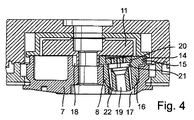
次に、図4を参照する。ここでは、個別ノズル本体8の1つが軸方向断面で示されている。個別ノズル本体8は、一端にシャワーヘッドハウジング2の内部に向けられた外側歯15を有する回転フランジ14を備える。これらの外側歯15は、図3の断面でも見ることができる。円筒断面16はフランジ14と隣接しており、後に半円断面に変わる。
Reference is now made to FIG. Here, one of the
個別ノズル本体8は、個別ノズル本体8の外形といくぶんか相補的に形成されたインサート7の容器に収容される。したがって、その円筒断面16では、個別ノズル本体8が容器の円筒壁に位置する一方、半円断面がリング表面に位置する。個別ノズル本体8の前部はインサート7の切り欠き17内にあるため、外方に開口している。
The
個別ノズル本体8のフランジ14の外側歯15には、回転子11のハブ上の外側歯18が協働しており、これは同様に図3の断面で見受けられる。回転子11は、インサート内に旋回可能に取り付けられる。
The
回転子11が流水によって回転させられると、個別ノズル本体8は容器によって定められる固定回転軸の周囲で回転させられる。
When the
個別ノズル本体8には段付きの内部開口19が設けられ、その長手方向軸は個別ノズル本体8の対称軸に対して斜めに延びている。個別ノズル本体8を回転させることによって、内部開口19の軸は円錐外囲に沿って移動する。
The
内部開口19は、噴射通路を形成しており、個別ノズル本体8のシャワーヘッドハウジング2の内部から離れる方の側から始まり、段の形で終結する第一の面を有する。数個の個別開口を備えた配水ディスク20が、この段上に位置する。配水ディスク20が位置する段には、混合室21が隣接することによって、段を備えた斜方向くびれを有することになる。この混合室21では、個別ノズル本体8の前面から出る内部開口19(噴射通路)に平行な4つの空気通路22が延びている。これらの小さな空気通路22は、図2でも見受けられる。
The
個別ノズル本体8の内部開口19(噴射通路)内で配水ディスク20の穴を通って水が流れると、水はシャワーヘッドハウジングの外側からの空気を空気通路22から吸い込み、その空気を内部開口19(噴射通路)を通って案内される噴射流へ運び込む。この空気の吸引と出て行く噴射流への空気混入は、回転子の回転とは独立している。回転する回転子と定期的に方向を変える水の噴射流によって、非常に多様な噴射パターンが生み出される。
When water flows through the hole of the
1 グリップ
2 シャワーヘッドハウジング
3 ハウジング面
4 円筒ジャケット
5 噴射ディスク
6 噴射口要素
7 インサート
8 個別ノズル本体
9 ねじ
10 中央突起
11 タービン翼車、回転子
12 スリット
13 リング空間
14 フランジ
15 外側歯
16 円筒断面
18 外側歯
19 内部開口
20 配水ディスク
21 混合室
22 空気通路
DESCRIPTION OF SYMBOLS 1 Grip 2
Claims (15)
前記シャワーヘッドハウジング(2)の内部の吸水管路と、
噴射口手段(6)を備えた噴射ディスク(5)と、
前記噴射ディスク(5)および/または前記シャワーヘッドハウジング(2)に対して移動可能に保持される少なくとも1つの個別ノズル本体(8)とを有し、
自身から出るシャワー噴射流に空気を混入させるための通気装置を備える衛生器具用シャワーヘッドであって、
前記個別ノズル本体(8)が前記シャワーヘッドハウジング(2)および/または前記噴射ディスク(5)に保持される、シャワーヘッド。Shower head housing (2);
A water absorption conduit inside the shower head housing (2);
An injection disc (5) provided with injection means (6);
Having at least one individual nozzle body (8) held movably with respect to the spray disc (5) and / or the showerhead housing (2);
A shower head for sanitary ware equipped with a venting device for mixing air into a shower jet flowing from itself,
Shower head, wherein the individual nozzle body (8) is held in the shower head housing (2) and / or the spray disc (5).
前記シャワーヘッドハウジング(2)の内部の吸水管路と、
噴射口手段(6)を備えた噴射ディスク(5)と、
前記噴射ディスク(5)および/または前記シャワーヘッドハウジング(2)に対して移動可能に保持される少なくとも1つの個別ノズル本体(8)とを有し、
自身から出るシャワー噴射流に空気を混入させるための通気装置を備える衛生器具用シャワーヘッドであって、
前記個別ノズル本体(8)が前記シャワーヘッドハウジング(2)のインサート(7)内に保持される、シャワーヘッド。Shower head housing (2);
A water absorption conduit inside the shower head housing (2);
An injection disc (5) provided with injection means (6);
Having at least one individual nozzle body (8) held movably with respect to the spray disc (5) and / or the showerhead housing (2);
A shower head for sanitary ware equipped with a venting device for mixing air into a shower jet flowing from itself,
Shower head, wherein the individual nozzle body (8) is held in an insert (7) of the shower head housing (2).
Applications Claiming Priority (3)
| Application Number | Priority Date | Filing Date | Title |
|---|---|---|---|
| DE102004059329A DE102004059329A1 (en) | 2004-12-01 | 2004-12-01 | Shower head for a sanitary shower |
| DE102004059329.9 | 2004-12-01 | ||
| PCT/EP2005/012758 WO2006058717A1 (en) | 2004-12-01 | 2005-11-30 | Shower head for a sanitary shower |
Publications (2)
| Publication Number | Publication Date |
|---|---|
| JP2008521530A JP2008521530A (en) | 2008-06-26 |
| JP4958237B2 true JP4958237B2 (en) | 2012-06-20 |
Family
ID=35892462
Family Applications (1)
| Application Number | Title | Priority Date | Filing Date |
|---|---|---|---|
| JP2007543763A Active JP4958237B2 (en) | 2004-12-01 | 2005-11-30 | Sanitary ware shower head |
Country Status (12)
| Country | Link |
|---|---|
| US (1) | US7946512B2 (en) |
| EP (1) | EP1827705B1 (en) |
| JP (1) | JP4958237B2 (en) |
| CN (1) | CN100553789C (en) |
| AT (1) | ATE400364T1 (en) |
| DE (2) | DE102004059329A1 (en) |
| DK (1) | DK1827705T3 (en) |
| ES (1) | ES2309819T3 (en) |
| PL (1) | PL1827705T3 (en) |
| PT (1) | PT1827705E (en) |
| SI (1) | SI1827705T1 (en) |
| WO (1) | WO2006058717A1 (en) |
Families Citing this family (77)
| Publication number | Priority date | Publication date | Assignee | Title |
|---|---|---|---|---|
| US7114666B2 (en) | 2002-12-10 | 2006-10-03 | Water Pik, Inc. | Dual massage shower head |
| US7740186B2 (en) | 2004-09-01 | 2010-06-22 | Water Pik, Inc. | Drenching shower head |
| EP2007483A2 (en) | 2006-04-20 | 2008-12-31 | Water Pik, Inc. | Converging spray showerhead |
| US7789326B2 (en) | 2006-12-29 | 2010-09-07 | Water Pik, Inc. | Handheld showerhead with mode control and method of selecting a handheld showerhead mode |
| US8020787B2 (en) | 2006-11-29 | 2011-09-20 | Water Pik, Inc. | Showerhead system |
| US8366024B2 (en) | 2006-12-28 | 2013-02-05 | Water Pik, Inc. | Low speed pulsating showerhead |
| US7770822B2 (en) | 2006-12-28 | 2010-08-10 | Water Pik, Inc. | Hand shower with an extendable handle |
| US8794543B2 (en) | 2006-12-28 | 2014-08-05 | Water Pik, Inc. | Low-speed pulsating showerhead |
| US8789218B2 (en) | 2007-05-04 | 2014-07-29 | Water Pik, Inc. | Molded arm for showerheads and method of making same |
| DE102007058835A1 (en) * | 2007-11-30 | 2009-06-04 | Hansgrohe Ag | Ventilation arrangement for shower jets |
| USD624156S1 (en) | 2008-04-30 | 2010-09-21 | Water Pik, Inc. | Pivot ball attachment |
| DE102008028215A1 (en) | 2008-06-06 | 2009-12-10 | Hansgrohe Ag | shower head |
| DE102008038727B4 (en) * | 2008-08-12 | 2010-10-28 | Neoperl Gmbh | Sanitary water outlet |
| DE202008010717U1 (en) | 2008-08-12 | 2009-12-24 | Neoperl Gmbh | Sanitary water outlet |
| US8348181B2 (en) | 2008-09-15 | 2013-01-08 | Water Pik, Inc. | Shower assembly with radial mode changer |
| USD616061S1 (en) | 2008-09-29 | 2010-05-18 | Water Pik, Inc. | Showerhead assembly |
| CN101518759B (en) | 2009-01-14 | 2011-11-23 | 厦门松霖科技有限公司 | Rotary waterfall water bloom sprinkler |
| USD625776S1 (en) | 2009-10-05 | 2010-10-19 | Water Pik, Inc. | Showerhead |
| US20110114754A1 (en) * | 2009-11-18 | 2011-05-19 | Huasong ZHOU | Hydropower rotating overhead shower |
| US8616470B2 (en) | 2010-08-25 | 2013-12-31 | Water Pik, Inc. | Mode control valve in showerhead connector |
| WO2012025047A1 (en) * | 2010-08-27 | 2012-03-01 | 厦门松霖科技有限公司 | Aerating spray component for use in field of shower |
| CN101954325B (en) * | 2010-08-27 | 2013-03-27 | 厦门松霖科技有限公司 | Rich gas splashing component used in bathroom field |
| KR101053229B1 (en) * | 2010-09-01 | 2011-08-01 | 주식회사 로보터스 | Shower head making microbubble |
| CN102434985B (en) * | 2010-09-29 | 2013-03-27 | 北京清华阳光能源开发有限责任公司 | Water jet nozzle for solar water heating system |
| DE102011013534B3 (en) * | 2011-03-10 | 2012-03-22 | Grohe Ag | Jet forming element for a shower head |
| CN102872988B (en) * | 2011-07-12 | 2015-04-29 | 欣宇科技(福建)有限公司 | Mobile massage spray shower |
| DE202011104072U1 (en) * | 2011-08-05 | 2012-11-06 | Neoperl Gmbh | aerator |
| CN102489420A (en) * | 2011-11-22 | 2012-06-13 | 路达(厦门)工业有限公司 | Spraying rotary massaging water outlet structure |
| WO2013078977A1 (en) * | 2011-11-28 | 2013-06-06 | 厦门松霖科技有限公司 | Concealed top cover-type shower head |
| USD678467S1 (en) | 2012-01-27 | 2013-03-19 | Water Pik, Inc. | Ring-shaped handheld showerhead |
| USD678463S1 (en) | 2012-01-27 | 2013-03-19 | Water Pik, Inc. | Ring-shaped wall mount showerhead |
| USD692527S1 (en) | 2012-03-12 | 2013-10-29 | Kohler Co. | Shower faceplate |
| US9468939B2 (en) | 2012-03-12 | 2016-10-18 | Kohler Co. | Faceplate for shower device |
| CA2820623C (en) | 2012-06-22 | 2017-10-03 | Water Pik, Inc. | Bracket for showerhead with integral flow control |
| US9687859B2 (en) | 2012-11-16 | 2017-06-27 | Kohler Co. | Shower device |
| USD715896S1 (en) | 2013-03-15 | 2014-10-21 | Kohler Co. | Shower faceplate |
| USD716415S1 (en) | 2013-03-15 | 2014-10-28 | Kohler Co. | Shower faceplate |
| USD740917S1 (en) | 2013-03-16 | 2015-10-13 | Kohler Co. | Shower faceplate for shower device |
| USD715398S1 (en) | 2013-03-16 | 2014-10-14 | Kohler Co. | Shower faceplate |
| WO2014201420A1 (en) | 2013-06-13 | 2014-12-18 | Water Pik, Inc. | Showerhead with turbine driven shutter |
| USD719240S1 (en) | 2013-08-23 | 2014-12-09 | Kohler Co. | Shower device |
| WO2015042433A1 (en) | 2013-09-20 | 2015-03-26 | Moen Incorporated | Plumbing fixture fitting |
| CN203565221U (en) * | 2013-10-31 | 2014-04-30 | 厦门建霖工业有限公司 | Shower head with spraying angle adjustable |
| TWM475512U (en) * | 2013-11-21 | 2014-04-01 | bi-guang Cai | Water-flow generator with hydrostatic and condensing functions |
| DE102013224051A1 (en) * | 2013-11-25 | 2015-05-28 | Hansgrohe Se | Shower assembly with shower head housing |
| US9975128B2 (en) * | 2013-12-13 | 2018-05-22 | Xiamen Solex High-Tech Industries Co., Ltd. | Rotatable shower sprayer |
| USD745111S1 (en) | 2014-06-13 | 2015-12-08 | Water Pik, Inc. | Wall mount showerhead |
| USD744612S1 (en) | 2014-06-13 | 2015-12-01 | Water Pik, Inc. | Handheld showerhead |
| USD744065S1 (en) | 2014-06-13 | 2015-11-24 | Water Pik, Inc. | Handheld showerhead |
| USD744614S1 (en) | 2014-06-13 | 2015-12-01 | Water Pik, Inc. | Wall mount showerhead |
| USD744611S1 (en) | 2014-06-13 | 2015-12-01 | Water Pik, Inc. | Handheld showerhead |
| USD744066S1 (en) | 2014-06-13 | 2015-11-24 | Water Pik, Inc. | Wall mount showerhead |
| USD744064S1 (en) | 2014-06-13 | 2015-11-24 | Water Pik, Inc. | Handheld showerhead |
| WO2016032684A1 (en) * | 2014-08-28 | 2016-03-03 | Nebia Inc. | Immersive showerhead |
| CN104549802B (en) | 2014-12-26 | 2018-05-08 | 厦门松霖科技股份有限公司 | Discharging device and the shower including the discharging device |
| CN104646199B (en) * | 2015-02-11 | 2018-01-19 | 福建西河卫浴科技有限公司 | Delivery port of the same race has the discharge mechanism of different effluent functions |
| CA3084565A1 (en) | 2016-02-01 | 2017-08-10 | Water Pik, Inc. | Handheld pet spray wand |
| USD803981S1 (en) | 2016-02-01 | 2017-11-28 | Water Pik, Inc. | Handheld spray nozzle |
| DE102017203577B4 (en) | 2016-03-07 | 2019-08-08 | Hansgrohe Se | Shower head for ventilated shower jet |
| US10265710B2 (en) | 2016-04-15 | 2019-04-23 | Water Pik, Inc. | Showerhead with dual oscillating massage |
| USD970684S1 (en) | 2016-04-15 | 2022-11-22 | Water Pik, Inc. | Showerhead |
| WO2018049213A1 (en) | 2016-09-08 | 2018-03-15 | Water Pik, Inc. | Pause assembly for showerheads |
| USD960302S1 (en) | 2017-06-28 | 2022-08-09 | Phoenix Industries Pty Ltd | Shower head |
| USD843549S1 (en) | 2017-07-19 | 2019-03-19 | Water Pik, Inc. | Handheld spray nozzle |
| USD872227S1 (en) | 2018-04-20 | 2020-01-07 | Water Pik, Inc. | Handheld spray device |
| CN111036425A (en) * | 2018-10-15 | 2020-04-21 | 厦门松霖科技股份有限公司 | Water outlet assembly |
| CN109550611A (en) * | 2018-12-29 | 2019-04-02 | 厦门松霖科技股份有限公司 | Discharge mechanism and shower comprising the discharge mechanism |
| USD939047S1 (en) | 2019-02-22 | 2021-12-21 | Phoenix Industries Pty Ltd | Rail shower |
| USD939664S1 (en) * | 2019-02-22 | 2021-12-28 | Phoenix Industries Pty Ltd | Hand shower |
| USD939046S1 (en) | 2019-02-22 | 2021-12-21 | Phoenix Industries Pty Ltd | Hand shower |
| USD943709S1 (en) | 2019-02-22 | 2022-02-15 | Phoenix Industries Pty Ltd | Twin showers |
| USD972922S1 (en) | 2019-02-22 | 2022-12-20 | Phoenix Industries Pty Ltd | Hand shower bracket |
| USD954900S1 (en) | 2019-02-22 | 2022-06-14 | Phoenix Industries Pty Ltd | Rail shower |
| USD942599S1 (en) | 2019-02-22 | 2022-02-01 | Phoenix Industries Pty Ltd | Hand shower bracket |
| GB201913116D0 (en) * | 2019-09-11 | 2019-10-23 | Gjosa Sa | A shower head insert |
| USD955527S1 (en) * | 2021-08-05 | 2022-06-21 | Hongli Lin | Shower head |
| GB2606598B (en) * | 2021-09-02 | 2023-10-18 | Kohler Mira Ltd | A spray head |
Family Cites Families (15)
| Publication number | Priority date | Publication date | Assignee | Title |
|---|---|---|---|---|
| DE9005700U1 (en) * | 1990-05-19 | 1990-07-26 | Christophery Gmbh, 5860 Iserlohn, De | |
| JP2551815Y2 (en) * | 1991-01-30 | 1997-10-27 | 東陶機器株式会社 | Massage shower equipment |
| DE4109001A1 (en) * | 1991-03-19 | 1992-09-24 | Dornbracht Aloys F Gmbh | Shower head with fixed central part and distribution valve - has concentric rings of shower nozzles and interspersed air nozzles surrounded by horseshoe-shaped partitions |
| US5397064A (en) * | 1993-10-21 | 1995-03-14 | Heitzman; Charles J. | Shower head with variable flow rate, pulsation and spray pattern |
| GB2311474B (en) | 1996-03-27 | 1999-10-13 | Caradon Mira Ltd | Improvements in or relating to shower fitttings |
| US5862985A (en) * | 1996-08-09 | 1999-01-26 | The Rival Company | Showerhead |
| WO2000012221A1 (en) * | 1998-08-26 | 2000-03-09 | Teledyne Industries, Inc. D.B.A. Teledyne Water Pik | Multi-functional shower head |
| DE19912104A1 (en) * | 1999-03-18 | 2000-09-21 | Hansgrohe Ag | Shower head for a sanitary shower |
| GB2348615B (en) * | 1999-04-08 | 2003-07-16 | Alsons Corp | Showerhead engine assembly |
| US6254013B1 (en) * | 1999-07-13 | 2001-07-03 | Moen Incorporated | Spray head for use with low pressure fluid sources |
| DE10103649B4 (en) | 2001-01-27 | 2007-12-06 | Hansgrohe Ag | shower head |
| CN1318704C (en) * | 2001-11-09 | 2007-05-30 | 东陶机器株式会社 | Water discharge switching device |
| US7472846B2 (en) * | 2004-01-16 | 2009-01-06 | Masco Corporation Of Indiana | Integrated swivel spray aerator with diverter |
| EP1799355A1 (en) * | 2004-08-13 | 2007-06-27 | Joseph H. Clearman | Spray apparatus and dispensing tubes therefore |
| DE102004059328A1 (en) * | 2004-12-01 | 2006-06-08 | Hansgrohe Ag | Shower head for a sanitary shower |
-
2004
- 2004-12-01 DE DE102004059329A patent/DE102004059329A1/en not_active Withdrawn
-
2005
- 2005-11-30 EP EP05814361A patent/EP1827705B1/en active Active
- 2005-11-30 DK DK05814361T patent/DK1827705T3/en active
- 2005-11-30 PT PT05814361T patent/PT1827705E/en unknown
- 2005-11-30 SI SI200530411T patent/SI1827705T1/en unknown
- 2005-11-30 JP JP2007543763A patent/JP4958237B2/en active Active
- 2005-11-30 CN CNB2005800414078A patent/CN100553789C/en active Active
- 2005-11-30 DE DE502005004681T patent/DE502005004681D1/en active Active
- 2005-11-30 US US11/720,222 patent/US7946512B2/en not_active Expired - Fee Related
- 2005-11-30 AT AT05814361T patent/ATE400364T1/en active
- 2005-11-30 ES ES05814361T patent/ES2309819T3/en active Active
- 2005-11-30 PL PL05814361T patent/PL1827705T3/en unknown
- 2005-11-30 WO PCT/EP2005/012758 patent/WO2006058717A1/en active IP Right Grant
Also Published As
| Publication number | Publication date |
|---|---|
| US20080223957A1 (en) | 2008-09-18 |
| WO2006058717A1 (en) | 2006-06-08 |
| SI1827705T1 (en) | 2008-12-31 |
| EP1827705A1 (en) | 2007-09-05 |
| ES2309819T3 (en) | 2008-12-16 |
| ATE400364T1 (en) | 2008-07-15 |
| CN100553789C (en) | 2009-10-28 |
| PT1827705E (en) | 2008-08-26 |
| CN101080278A (en) | 2007-11-28 |
| JP2008521530A (en) | 2008-06-26 |
| DE502005004681D1 (en) | 2008-08-21 |
| DE102004059329A1 (en) | 2006-06-08 |
| US7946512B2 (en) | 2011-05-24 |
| DK1827705T3 (en) | 2008-11-03 |
| EP1827705B1 (en) | 2008-07-09 |
| PL1827705T3 (en) | 2008-12-31 |
Similar Documents
| Publication | Publication Date | Title |
|---|---|---|
| JP4958237B2 (en) | Sanitary ware shower head | |
| CA2690820C (en) | Revolving spray shower head | |
| US7584906B2 (en) | Fluid dampening mechanism incorporated into a water delivery system for modifying a flow pattern | |
| US7156322B1 (en) | Irrigation sprinkler unit with cycling flow rate | |
| EP2401089B1 (en) | Showerhead | |
| US20080011880A1 (en) | Sanitary Showerhead | |
| JP5891527B2 (en) | Shower water discharge device | |
| MXPA01005014A (en) | Showerhead for delivering an aerated water stream by use of the venturi effect. | |
| JP2008057309A (en) | Aeration nozzle device of warm water washing device | |
| JPH01153104A (en) | Hand spray | |
| TWI765920B (en) | Showerhead and showerhead engine for rotating spray | |
| CN101213027B (en) | Shower head | |
| JP4381563B2 (en) | Dental handpiece | |
| US20060180681A1 (en) | Faucet adaptor | |
| JP2551815Y2 (en) | Massage shower equipment | |
| JP2766972B2 (en) | Rotary fountain rotary drive | |
| JP5895559B2 (en) | Nozzle device for jet bath | |
| JPH0857011A (en) | Jet feeder into bathtub | |
| JP2006068515A (en) | Device for supplying jet inside bathtub | |
| JP2003116729A (en) | Rotary nozzle device for jet bath | |
| JP2001017890A (en) | Spray nozzle | |
| JPH06182265A (en) | Rotary fountain device | |
| JPH02218459A (en) | Fluid rotary nozzle | |
| JP2005124752A (en) | Hand shower with massage function |
Legal Events
| Date | Code | Title | Description |
|---|---|---|---|
| A621 | Written request for application examination |
Free format text: JAPANESE INTERMEDIATE CODE: A621 Effective date: 20080415 |
|
| A131 | Notification of reasons for refusal |
Free format text: JAPANESE INTERMEDIATE CODE: A131 Effective date: 20100622 |
|
| A601 | Written request for extension of time |
Free format text: JAPANESE INTERMEDIATE CODE: A601 Effective date: 20100802 |
|
| A602 | Written permission of extension of time |
Free format text: JAPANESE INTERMEDIATE CODE: A602 Effective date: 20100809 |
|
| A521 | Request for written amendment filed |
Free format text: JAPANESE INTERMEDIATE CODE: A523 Effective date: 20100913 |
|
| A131 | Notification of reasons for refusal |
Free format text: JAPANESE INTERMEDIATE CODE: A131 Effective date: 20110308 |
|
| A601 | Written request for extension of time |
Free format text: JAPANESE INTERMEDIATE CODE: A601 Effective date: 20110502 |
|
| A602 | Written permission of extension of time |
Free format text: JAPANESE INTERMEDIATE CODE: A602 Effective date: 20110512 |
|
| A601 | Written request for extension of time |
Free format text: JAPANESE INTERMEDIATE CODE: A601 Effective date: 20110614 |
|
| A602 | Written permission of extension of time |
Free format text: JAPANESE INTERMEDIATE CODE: A602 Effective date: 20110621 |
|
| A521 | Request for written amendment filed |
Free format text: JAPANESE INTERMEDIATE CODE: A523 Effective date: 20110819 |
|
| TRDD | Decision of grant or rejection written | ||
| A01 | Written decision to grant a patent or to grant a registration (utility model) |
Free format text: JAPANESE INTERMEDIATE CODE: A01 Effective date: 20120313 |
|
| A01 | Written decision to grant a patent or to grant a registration (utility model) |
Free format text: JAPANESE INTERMEDIATE CODE: A01 |
|
| A61 | First payment of annual fees (during grant procedure) |
Free format text: JAPANESE INTERMEDIATE CODE: A61 Effective date: 20120315 |
|
| FPAY | Renewal fee payment (event date is renewal date of database) |
Free format text: PAYMENT UNTIL: 20150330 Year of fee payment: 3 |
|
| R150 | Certificate of patent or registration of utility model |
Ref document number: 4958237 Country of ref document: JP Free format text: JAPANESE INTERMEDIATE CODE: R150 Free format text: JAPANESE INTERMEDIATE CODE: R150 |
|
| R250 | Receipt of annual fees |
Free format text: JAPANESE INTERMEDIATE CODE: R250 |
|
| R250 | Receipt of annual fees |
Free format text: JAPANESE INTERMEDIATE CODE: R250 |
|
| R250 | Receipt of annual fees |
Free format text: JAPANESE INTERMEDIATE CODE: R250 |
|
| R250 | Receipt of annual fees |
Free format text: JAPANESE INTERMEDIATE CODE: R250 |
|
| R250 | Receipt of annual fees |
Free format text: JAPANESE INTERMEDIATE CODE: R250 |
|
| R250 | Receipt of annual fees |
Free format text: JAPANESE INTERMEDIATE CODE: R250 |
|
| R250 | Receipt of annual fees |
Free format text: JAPANESE INTERMEDIATE CODE: R250 |
|
| R250 | Receipt of annual fees |
Free format text: JAPANESE INTERMEDIATE CODE: R250 |
|
| R250 | Receipt of annual fees |
Free format text: JAPANESE INTERMEDIATE CODE: R250 |