JP4955972B2 - Data communication apparatus, control method therefor, and program - Google Patents
Data communication apparatus, control method therefor, and program Download PDFInfo
- Publication number
- JP4955972B2 JP4955972B2 JP2005280104A JP2005280104A JP4955972B2 JP 4955972 B2 JP4955972 B2 JP 4955972B2 JP 2005280104 A JP2005280104 A JP 2005280104A JP 2005280104 A JP2005280104 A JP 2005280104A JP 4955972 B2 JP4955972 B2 JP 4955972B2
- Authority
- JP
- Japan
- Prior art keywords
- data
- input
- received
- data communication
- determination
- Prior art date
- Legal status (The legal status is an assumption and is not a legal conclusion. Google has not performed a legal analysis and makes no representation as to the accuracy of the status listed.)
- Expired - Fee Related
Links
Images


Classifications
-
- H—ELECTRICITY
- H04—ELECTRIC COMMUNICATION TECHNIQUE
- H04N—PICTORIAL COMMUNICATION, e.g. TELEVISION
- H04N1/00—Scanning, transmission or reproduction of documents or the like, e.g. facsimile transmission; Details thereof
-
- H—ELECTRICITY
- H04—ELECTRIC COMMUNICATION TECHNIQUE
- H04N—PICTORIAL COMMUNICATION, e.g. TELEVISION
- H04N1/00—Scanning, transmission or reproduction of documents or the like, e.g. facsimile transmission; Details thereof
- H04N1/00127—Connection or combination of a still picture apparatus with another apparatus, e.g. for storage, processing or transmission of still picture signals or of information associated with a still picture
- H04N1/00281—Connection or combination of a still picture apparatus with another apparatus, e.g. for storage, processing or transmission of still picture signals or of information associated with a still picture with a telecommunication apparatus, e.g. a switched network of teleprinters for the distribution of text-based information, a selective call terminal
-
- H—ELECTRICITY
- H04—ELECTRIC COMMUNICATION TECHNIQUE
- H04N—PICTORIAL COMMUNICATION, e.g. TELEVISION
- H04N1/00—Scanning, transmission or reproduction of documents or the like, e.g. facsimile transmission; Details thereof
- H04N1/0035—User-machine interface; Control console
-
- H—ELECTRICITY
- H04—ELECTRIC COMMUNICATION TECHNIQUE
- H04N—PICTORIAL COMMUNICATION, e.g. TELEVISION
- H04N1/00—Scanning, transmission or reproduction of documents or the like, e.g. facsimile transmission; Details thereof
- H04N1/0035—User-machine interface; Control console
- H04N1/00405—Output means
- H04N1/00477—Indicating status, e.g. of a job
-
- H—ELECTRICITY
- H04—ELECTRIC COMMUNICATION TECHNIQUE
- H04N—PICTORIAL COMMUNICATION, e.g. TELEVISION
- H04N1/00—Scanning, transmission or reproduction of documents or the like, e.g. facsimile transmission; Details thereof
- H04N1/0035—User-machine interface; Control console
- H04N1/00405—Output means
- H04N1/0048—Indicating an illegal or impossible operation or selection to the user
-
- H—ELECTRICITY
- H04—ELECTRIC COMMUNICATION TECHNIQUE
- H04N—PICTORIAL COMMUNICATION, e.g. TELEVISION
- H04N1/00—Scanning, transmission or reproduction of documents or the like, e.g. facsimile transmission; Details thereof
- H04N1/00912—Arrangements for controlling a still picture apparatus or components thereof not otherwise provided for
- H04N1/00933—Timing control or synchronising
-
- H—ELECTRICITY
- H04—ELECTRIC COMMUNICATION TECHNIQUE
- H04N—PICTORIAL COMMUNICATION, e.g. TELEVISION
- H04N1/00—Scanning, transmission or reproduction of documents or the like, e.g. facsimile transmission; Details thereof
- H04N1/32—Circuits or arrangements for control or supervision between transmitter and receiver or between image input and image output device, e.g. between a still-image camera and its memory or between a still-image camera and a printer device
- H04N1/32609—Fault detection or counter-measures, e.g. original mis-positioned, shortage of paper
- H04N1/32646—Counter-measures
- H04N1/32651—Indicating or reporting
-
- H—ELECTRICITY
- H04—ELECTRIC COMMUNICATION TECHNIQUE
- H04N—PICTORIAL COMMUNICATION, e.g. TELEVISION
- H04N1/00—Scanning, transmission or reproduction of documents or the like, e.g. facsimile transmission; Details thereof
- H04N1/32—Circuits or arrangements for control or supervision between transmitter and receiver or between image input and image output device, e.g. between a still-image camera and its memory or between a still-image camera and a printer device
- H04N1/327—Initiating, continuing or ending a single-mode communication; Handshaking therefor
- H04N1/32704—Establishing a communication with one of a facsimile and another telecommunication apparatus sharing a single line
- H04N1/32739—Generating signals
- H04N1/32745—Generating messages, indications or warnings locally
-
- H—ELECTRICITY
- H04—ELECTRIC COMMUNICATION TECHNIQUE
- H04N—PICTORIAL COMMUNICATION, e.g. TELEVISION
- H04N1/00—Scanning, transmission or reproduction of documents or the like, e.g. facsimile transmission; Details thereof
- H04N1/32—Circuits or arrangements for control or supervision between transmitter and receiver or between image input and image output device, e.g. between a still-image camera and its memory or between a still-image camera and a printer device
- H04N1/327—Initiating, continuing or ending a single-mode communication; Handshaking therefor
- H04N1/32765—Initiating a communication
- H04N1/32771—Initiating a communication in response to a request, e.g. for a particular document
- H04N1/32776—Initiating a communication in response to a request, e.g. for a particular document using an interactive, user-operated device, e.g. a computer terminal, mobile telephone
-
- H—ELECTRICITY
- H04—ELECTRIC COMMUNICATION TECHNIQUE
- H04N—PICTORIAL COMMUNICATION, e.g. TELEVISION
- H04N2201/00—Indexing scheme relating to scanning, transmission or reproduction of documents or the like, and to details thereof
- H04N2201/0008—Connection or combination of a still picture apparatus with another apparatus
- H04N2201/0015—Control of image communication with the connected apparatus, e.g. signalling capability
- H04N2201/0017—Notifying a communication result
-
- H—ELECTRICITY
- H04—ELECTRIC COMMUNICATION TECHNIQUE
- H04N—PICTORIAL COMMUNICATION, e.g. TELEVISION
- H04N2201/00—Indexing scheme relating to scanning, transmission or reproduction of documents or the like, and to details thereof
- H04N2201/0008—Connection or combination of a still picture apparatus with another apparatus
- H04N2201/0072—Detecting the status of a connected apparatus
Description
本発明は、ネットワークを介してデータを受信するデータ通信装置及びその制御方法、プログラムに関するものである。 The present invention relates to a data communication apparatus that receives data via a network, a control method thereof, and a program.
従来から、外部装置と通信可能なデータ通信装置において、データの受信に関する情報を通知するための技術が知られている。 2. Description of the Related Art Conventionally, a technique for notifying information related to data reception in a data communication device capable of communicating with an external device is known.
例えば、外部装置であるファクシミリ装置から親展IDを含む親展文書を受信した場合に、受信した親展文書に含まれる親展IDに対応するメールアドレスに対して、親展文書を受信したことを電子メールにより通知するファクシミリ装置が知られている。(例えば、特許文献1参照)
また、外部装置であるファクシミリ装置が文書を送信してきた際に、文書を受信することが出来ない場合には、その旨を送信元のファクシミリ装置に通知するファクシミリ装置が知られている。(例えば、特許文献2参照)
In addition, there is known a facsimile apparatus that notifies a transmission source facsimile apparatus when a document cannot be received when a facsimile apparatus as an external apparatus transmits the document. (For example, see Patent Document 2)
しかしながら、上述した従来技術では次のような問題があった。 However, the above-described prior art has the following problems.
例えば、データ通信装置が外部装置から所定の受信期間(例えば予め決められた時刻)にある文書を受信する予定になっている場合を想定する。この場合、所定の受信期間に、受信すべき文書を受信していない場合には、受信者は何度も装置を操作して受信したかどうかを確認しなければならず、使い勝手が悪い。また、送信すべきユーザが送信を忘れていた場合には、その旨を受信側のユーザが送信側のユーザに伝えなければならず煩わしいという問題がある。 For example, it is assumed that the data communication apparatus is scheduled to receive a document in a predetermined reception period (for example, a predetermined time) from an external apparatus. In this case, if a document to be received has not been received in a predetermined reception period, the receiver must confirm whether or not the document has been received by operating the apparatus many times, which is inconvenient. Moreover, when the user who should transmit has forgotten transmission, there exists a problem that the user on the receiving side has to tell the user on the transmitting side to that effect.
また、例えばデータ通信装置が外部装置へ所定の文書の送信を要求して、外部装置から送信された文書を受信する場合を想定する。この場合には、所定の文書の送信を要求した際に、外部装置から文書が送信されてこない状態である場合には、受信側のユーザが送信側のユーザに問い合わせを行うなどの煩わしい作業を行う必要がある。 Further, for example, a case is assumed where the data communication apparatus requests the external apparatus to transmit a predetermined document and receives the document transmitted from the external apparatus. In this case, when a request for transmission of a predetermined document is made and the document is not transmitted from an external device, a troublesome operation such as an inquiry from the user on the receiving side to the user on the transmitting side is performed. There is a need to do.
本発明は、上記の問題点に鑑みなされたものであり、本来は受信すべき所定のデータが受信されていない場合に、その旨を示す情報を出力することができるデータ通信装置及びその制御方法、プログラムを提供することを目的とする。 The present invention has been made in view of the above problems, and a data communication apparatus capable of outputting information indicating that when predetermined data to be originally received is not received, and a control method therefor The purpose is to provide a program.
上記の目的を達成するために本発明のデータ通信装置は、複数の送信元からデータを受信することが可能な受信手段と、前記受信手段で受信するデータの中から、受信すべき所定のデータを特定するための条件として、少なくとも前記所定のデータの送信元を特定する送信元特定情報と、前記所定のデータを受信すべき周期的な期間を特定する受信期間特定情報とを入力する入力手段と、前記入力手段により入力された条件を満たすデータが前記受信手段により受信されているか否かを判定する判定手段と、前記判定手段による判定の結果、前記入力手段により入力された条件を満たすデータが前記受信手段により受信されていないと判定された場合に、前記所定のデータが受信されていないことを前記送信元特定情報が示す送信元に通知する通知手段とを備えることを特徴とする。 In order to achieve the above object, a data communication apparatus according to the present invention includes a receiving unit capable of receiving data from a plurality of transmission sources, and predetermined data to be received from data received by the receiving unit. Input means for inputting at least transmission source specifying information for specifying the transmission source of the predetermined data and reception period specifying information for specifying a periodic period in which the predetermined data is to be received as conditions for specifying the predetermined data Determining means for determining whether or not the data that satisfies the condition input by the input means is received by the receiving means; and the data that satisfies the condition input by the input means as a result of the determination by the determining means Is determined not to be received by the receiving means, the transmission source indicated by the transmission source identification information is notified that the predetermined data has not been received. Characterized in that it comprises a notifying means.
本発明によれば、受信すべき所定のデータの送信元を特定する送信元特定情報と当該所定のデータを受信すべき周期的な期間を特定する受信期間特定情報とに基づいて、当該所定のデータが受信されているか否かを判定し、受信されていないと判定された場合に、その旨を当該所定のデータを送信すべき送信元に対して通知することができる。特に、周期的な期間で繰り返し所定のデータを受信する場合においても、手間をかけずに送信元に対する通知を行うことができる。 According to the present invention, based on the transmission source specifying information for specifying the transmission source of the predetermined data to be received and the reception period specifying information for specifying the periodic period for receiving the predetermined data, the predetermined data It determines whether data is being received, when it is determined not to have been received, it is possible to notify to the transmission source to transmit the predetermined data. In particular, even when predetermined data is repeatedly received in a periodic period, notification to the transmission source can be performed without trouble.
以下に、本発明の実施形態を説明する。 Hereinafter, embodiments of the present invention will be described.
(第1の実施形態)
本発明の実施形態にかかわるデータ入出力システムの全体構成を、図1を参照して説明する。
(First embodiment)
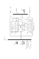
An overall configuration of a data input / output system according to an embodiment of the present invention will be described with reference to FIG.
リーダー部130は、原稿画像を光学的に読取り、画像データに変換する。リーダー部130は、原稿を読取るための機能を持つスキャナユニット131と、原稿用紙を搬送するための機能を持つ原稿給紙ユニット132とで構成される。
The
プリンタ部140は、記録紙を搬送し、その上に画像データを可視画像として印字して装置外に排紙する。プリンタ部140は、複数種類の記録紙カセットを持つ給紙ユニット142、画像データを記録紙に転写、定着させる機能を持つマーキングユニット141、及び印字された記録紙をソート、ステイプルして排紙する機能を持つ排紙ユニット143で構成される。
The
制御装置110は、リーダー部130、プリンタ部140と電気的に接続されるとともに、ネットワークを介して外部機器と接続されている。具体的には、制御装置110はLAN150を介してホストコンピュータ151、152と接続され、さらに公衆回線160を介してファクシミリ装置161と接続されている。
The control device 110 is electrically connected to the
制御装置110は、リーダー部130を制御して原稿の画像データを読込み、プリンタ部140を制御して画像データを記録出力することでコピー機能を提供する。また、制御装置110は、リーダー部130から読取った画像データをコードデータに変換し、LAN150を介してホストコンピュータへ送信するスキャナ機能を提供する。また、制御装置110は、ホストコンピュータ151、152からLAN150を介して受信したコードデータを画像データに変換し、プリンタ部140に出力するプリンタ機能を提供する。
The control device 110 provides a copy function by controlling the
さらに、制御装置110は、インターネットファクシミリ(IFAX)機能を用いて、ホストコンピュータ151、152からLAN150を介して、ファクシミリ形式の画像データが添付された電子メール(Eメール)を受信することができる。この時、ホストコンピュータ151、152はSMTP(Simple Mail Transfer Protocol)を用いてSMTPサーバ153へ電子メールを送信する。そして、SMTPサーバ153は電子メールアドレスにより特定されるPOPサーバ154へ電子メールを転送する。 Furthermore, the control device 110 can receive an electronic mail (e-mail) attached with image data in the facsimile format from the host computers 151 and 152 via the LAN 150 using the Internet facsimile (IFAX) function. At this time, the host computers 151 and 152 transmit an e-mail to the SMTP server 153 by using SMTP (Simple Mail Transfer Protocol). Then, the SMTP server 153 transfers the e-mail to the POP server 154 specified by the e-mail address.
制御装置110は、インターネットファクシミリ機能を用いて電子メールを受信する際、POP3(Post Office Protocol Version3)を用いて、POP3サーバ154に蓄積された電子メールを受信する。また、SMTPを用いても受信可能である。 When the electronic mail is received using the Internet facsimile function, the control device 110 receives the electronic mail stored in the POP3 server 154 using POP3 (Post Office Protocol Version 3). It can also be received using SMTP.
また、制御装置110は、ファクシミリ装置161から公衆回線160を介してファクシミリデータを受信することができる。なお、ファクシミリデータの受信にあたって制御装置110は、ITU−T勧告T.30に規定されたG3ファクシミリの通信プロトコルを用いる。
Further, the control device 110 can receive facsimile data from the facsimile device 161 via the
操作部120は、制御装置110に接続され、液晶タッチパネルと複数のハードキーで構成され、データ入出力システムを操作するためのユーザI/F(Interface)を提供する。
The
<リーダー部とプリンタ部の説明>
リーダー部130とプリンタ部140とは、図2に示すように、一体的に構成されている。
<Explanation of reader and printer>
The
リーダー部130は、原稿給紙ユニット132を搭載し、原稿給紙ユニット132は、原稿を先頭から順に1枚ずつプラテンガラス231上へ給送し、各原稿の読取動作が終了する毎に、その原稿をプラテンガラス231から排出トレイ(図示せず)に排出する。
The
リーダー部130は、原稿がプラテンガラス231上に給送されると、ランプ232を点灯し、移動ユニット233の移動を開始する。この移動ユニット233の移動によりプラテンガラス231上の原稿に対する読取走査が行われる。この読取走査中、原稿からの反射光は、各ミラー234,235,236およびレンズ237を経てCCDイメージセンサ(以下、「CCD」という)238に導かれ、原稿上の画像がCCD238の撮像面上に結像される。
When the document is fed onto the
CCD238は、撮像面に結像された画像を電気信号に変換し、この電気信号に所定の処理が施された後に制御装置110に入力される。
The
プリンタ部140は、レーザドライバ241を有し、レーザドライバ241は、制御装置から入力された画像データに基づきレーザ発光部242を駆動する。これにより、レーザ発光部242からは画像データに応じたレーザ光が発光され、このレーザ光は走査されながら感光ドラム243上に照射される。
The
感光ドラム243上には、照射されたレーザ光により静電潜像が形成され、この静電潜像は現像器244から供給されたトナーによりトナー像として可視像化される。レーザ光の照射期間に同期して、各カセット261、262から記録紙が搬送路を介して感光ドラム243と転写部245との間に給紙され、感光ドラム243上のトナー像は転写部245により給紙された記録紙上に転写される。
An electrostatic latent image is formed on the
トナー像が転写された記録紙は、搬送ベルトを介して定着ローラ対(加熱ローラと加圧ローラ)246に送られ、定着ローラ対246は記録紙を熱圧し、記録紙上のトナー像を記録紙上に定着させる。この定着ローラ対246を通過した記録紙は、排紙ローラ対247により排紙ユニット143に排紙される。排紙ユニット143は、ソート、ステイプルなどの後処理を施すことが可能なシート処理装置からなる。
The recording paper on which the toner image has been transferred is sent to a fixing roller pair (heating roller and pressure roller) 246 via a conveyance belt, and the
また、両面記録モードが設定されている場合には、記録紙を排紙ローラ対247まで搬送した後に、排紙ローラ対247の回転方向を逆転させ、フラッパ248によって再給紙搬送路251へ導く。再給紙搬送路251に導かれた記録紙は、上述した照射期間で感光ドラム243と転写部245との間に再給紙され、この記録紙の裏面にトナー像が転写される。
When the duplex recording mode is set, after the recording sheet is conveyed to the discharge roller pair 247, the rotation direction of the discharge roller pair 247 is reversed and guided to the
<制御装置の説明>
制御装置110の機能を、図3に示すブロック図をもとに説明する。
<Description of control device>
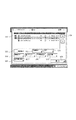
The function of the control device 110 will be described based on the block diagram shown in FIG.
メインコントローラ311にはCPU(Central Processing Unit)、レンダリング部,メモリコントローラ,シリアル通信制御部,シリアルバス制御部などが含まれている。 The main controller 311 includes a CPU (Central Processing Unit), a rendering unit, a memory controller, a serial communication control unit, a serial bus control unit, and the like.
CPU337は制御装置110全体の動作を制御するものであり、Memory321に格納されたプログラムに基づいて動作する。また、ホストコンピュータから受信したPDL(Page Description Language)データを解釈し、ラスターイメージデータに展開する動作もこのプログラムに記述されている。受信したコードデータの解釈はCPU337で行われ、ラスターイメージデータの展開はレンダリング部で処理される。 The CPU 337 controls the operation of the entire control device 110 and operates based on a program stored in the Memory 321. The program also describes an operation of interpreting PDL (Page Description Language) data received from the host computer and developing it into raster image data. The CPU 337 interprets the received code data, and raster image data development is processed by the rendering unit.
レンダリング部ではCPU337で作成されたコードデータに基づいてラスターイメージデータを作成し、Memory321や、プリンタ画像処理部351に展開後のラスターデータを転送する。レンダリング部で作成されるイメージデータの色空間はRGB、CMYKが挙げられる。
The rendering unit creates raster image data based on the code data created by the CPU 337, and transfers the raster data after development to the Memory 321 or the printer
シリアル通信制御部はプリンタ部140のCPUとシリアルバスを介して制御コマンドを送受信して通信を行う。シリアルバス制御部ではホストコンピュータとの通信、各種デバイスとの通信がコネクタ322を介して行われる。シリアルバスとしては一般的にUSB(Universal Serial Bus)があげられ、ホストコンピュータからPDLデータを受信するI/Fとして用いられる。
The serial communication control unit communicates with the CPU of the
コネクタ323にはシリアルバスが接続され、リーダコントローラ部との通信や、画像データの転送に用いられる。BootROM324はCPU337が起動するプログラムが格納されており、また場合によってはPDL用のフォントデータが格納される。クロック353は現在時刻をカウントしている。
A serial bus is connected to the connector 323, and is used for communication with the reader controller unit and transfer of image data. The BootROM 324 stores a program that is started by the CPU 337, and in some cases, font data for PDL is stored. The
汎用高速バス330には、拡張ボードを接続するための拡張コネクタ335とI/O(Input/Output)制御コントローラ部336、HD(ハードディスク)コントローラ331、音声出力部333が接続される。汎用高速バスとしては、一般的にPCIバスがあげられる。
An expansion connector 335 for connecting an expansion board, an I / O (Input / Output)
HDコントローラ331は、外部記憶装置を接続するためのものである。本実施例においては、このI/Fを介してハードディスクドライブ332を接続している。ハードディスク332はプログラムを格納したり、読取りまたは受信した画像データを記憶する記憶部として用いられる。
The
I/O制御コントローラ336は、データバス391の制御を行い、ポートや割り込みの制御を行う。また、I/O制御コントローラ336にはCPU337が搭載され、ポート制御338の制御やNetwork Controller340、操作部120との通信、Modem346との通信等を制御する。
The I /
Network Controller340は外部ネットワーク347と接続される。この時、ネットワークの例としては一般的にイーサネット(登録商標)があげられ、ホストコンピュータからのPDLデータ受信や、リーダー部130で読取った画像の送信、ネットワークを介して端末の管理を行うリモート管理等に用いられる。
The
Modem346は外部ネットワークである公衆回線349に接続され、ファクシミリの通信を行う。Memory339はCPU337のワーク用メモリ、操作部120に表示する画像データのワーク用メモリ等に用いられる。また、さらにMemory339は外部機器とのデータ通信の送受信に関する履歴情報を記憶する。Memory339が記憶する履歴情報は外部装置または操作部120からの要求で読み出されて、操作部120で表示またはプリンタ部140でプリント、または各I/Fを介して外部機器に送信される。
The
音声出力部333は音声信号を出力する為のもので、汎用高速バス330から入力されたデータに基づいてスピーカー334に信号を出力する。
The
操作部I/F345は操作部120の液晶画面に表示を行うためのI/Fと、ハードキーやタッチパネルキーの入力を行うためのキー入力I/Fとから構成される。
The operation unit I /
操作部120は液晶表示部と液晶表示部上に張り付けられたタッチパネル入力装置と、複数個のハードキーを有する。タッチパネルまたはハードキーにより入力された信号は、前述した操作部I/F345を介して入力されたハードキーのID番号と入力されたタッチパネルの座標情報としてCPU337に伝えられる。
The
液晶表示部は操作部I/F345から送られてきた画像データを表示するものである。液晶表示部には、本画像形成装置の操作における機能表示や画像データ等を表示する。
The liquid crystal display unit displays image data sent from the operation unit I /
FAN348はI/O制御コントローラ336に接続され、コントローラ部110を冷却するのに用いる。
The
SRAM341はバックアック用電池344でバックアップされており、ユーザーモードや各種設定情報を登録でき、ハードディスクドライブ332のファイル管理情報等を蓄積している。
The
リアルタイムクロックモジュール343は、機器内で管理する日付と時刻を更新/保存するためのもので、バックアップ電池344によってバックアップされている。
The real
プリンタ画像処理部351は、カスタムバス325と高速バス350でメインコントローラ311と接続されている。高速バス350は片方向通信でリング状に接続されている。
The printer
プリンタ画像処理部351は、コネクタ381を介してプリンタ部140と接続され、メインコントローラ311から入力された画像データに所定の画像処理を施して、メインコントローラ311もしくはプリンタ部140へ出力する機能を有する。Memory352はプリンタ画像処理351のワーク領域および遅延バッファとして使用される。
The printer
<操作部概要>
操作部120の構成を図4に示す。LCD表示部410は、LCD上にタッチパネルシートが貼られており、システムの操作画面を表示するとともに、表示してあるキーが押されるとその位置情報を制御装置のCPU337に伝える。
<Operation section overview>
The configuration of the
スタートキー420は原稿画像の読取り動作を開始する時などに用いる。スタートキー中央部には、緑と赤の2色LEDがあり、その色によってスタートキーが使える状態にあるかどうかを示す。ストップキー430は稼働中の動作を止める働きをする。
A
ハードキー群440には、テンキー、クリアキー、リセットキー、ガイドキー、ユーザーモードキー、IDキーが設けられている。IDキーは使用者のユーザIDを入力するときに用いる。リセットキーは操作部からの設定を初期化するときに用いる。ユーザーモードキーはユーザーモードにおいて各種設定を行う場合に用いる。
The hard
<操作画面>
本実施形態の装置が提供する機能は、コピー/送信・ファクシミリ/ボックス/リモートスキャナの4つの大きなカテゴリーに分かれており、これらは図5に示す操作画面の上部に表示される4つのメインタブ501〜504に対応している。これらのメインタブを押すことにより、各カテゴリーの画面への切り替えが行われる。
<Operation screen>
The functions provided by the apparatus of this embodiment are divided into four major categories: copy / transmission / facsimile / box / remote scanner, and these are the four
「コピー」は自機が有するスキャナとプリンタを使用して通常のドキュメント複写を行う。「送信」は画像データを、電子メール送信、ファイル転送、ボックス保存またはデータベース転送する機能であり、宛先を複数指定することが可能である。「ファクシミリ」はファクシミリの送受信を行う。ここではまた、ファクシミリのポーリング通信を行うこともできる。 “Copy” performs normal document copying using the scanner and printer of the device itself. “Send” is a function for sending image data by e-mail, file transfer, box storage, or database transfer, and a plurality of destinations can be designated. “Facsimile” performs facsimile transmission / reception. Here, it is also possible to perform facsimile polling communication.
「ボックス」はリーダー部130で読み込んだデータ、ファックスで受信したデータ、またはホストから受信してPDLデータに展開したデータなどを自機が有するハードディスクに保存する機能である。また、ボックスに保存したものを読み出して、印刷や送信することも可能である。「リモートスキャナ」はホストコンピュータからの指示に応じて画像を読み込んで、読み込んだ画像データをホストコンピュータに取り込む機能である。
The “box” is a function for storing data read by the
操作画面に表示されたボタン及びハードキー群には各々にユニークなキーIDが割り振られ、キー入力を受け付けると各キーID情報を基に画面切り替えや設定等の処理が行われる。また、キーIDには振動設定情報と音声出力情報が割当てられている。 A unique key ID is assigned to each button and hard key group displayed on the operation screen. When a key input is accepted, processing such as screen switching and setting is performed based on each key ID information. Further, vibration setting information and audio output information are assigned to the key ID.
以下、これらの機能設定を行う方法をLCD画面表示の例を使用して説明する。 Hereinafter, a method for setting these functions will be described using an example of an LCD screen display.
コピー画面
コピー基本画面表示時にスタートボタンを押すと、リーダー部130が動作し、選択されているプリンタから画面上に表示されている各設定パラメータに応じた複写物が出力される。
Copy screen When the start button is pressed while the copy basic screen is displayed, the
図5にコピー基本画面を示す。コピー基本画面は、拡大縮小設定ボタン511・512、用紙選択ボタン513、ソータ設定ボタン516、両面コピー設定ボタン517、濃度設定ボタン514、文字/写真設定ボタン515、応用モード設定ボタン519などから構成される。
FIG. 5 shows a copy basic screen. The basic copy screen is composed of enlargement /
各種コピーパラメータ設定ボタン511〜517を選択すると、それぞれに対応したサブ画面(拡大縮小設定、用紙選択、濃度設定、ソータ設定、両面コピー設定、文字/写真設定)が表示され、パラメータを設定することができる。
When various copy
応用モード設定ボタン519を選択すると、図6に示す様にページ連写や縮小レイアウト等の各応用機能設定ボタンを表示する。これらの機能設定ボタンを選択すると、それぞれに対応したサブ画面が表示され、各種応用モードのパラメータを設定することが出来る。
When the application
送信/ファクシミリ画面
送信/ファクシミリ基本画面表示時にスタートボタンを押すと、リーダー部130が動作し、読取った画像データを設定された宛先に指定された送信方法で送信する処理が開始される。
Transmission / facsimile screen When the start button is pressed while the transmission / facsimile basic screen is displayed, the
図7に送信/ファクシミリ基本画面を示す。送信/ファクシミリ基本画面は、宛先表示領域710、宛先スクロールボタン712、アドレスブックボタン713、送信方法選択ボタン721〜725、編集ボタン714、消去ボタン715、送信設定ボタン744、読込設定ボタン731などから構成される。リセットを含む初期化時には図7に示すように、宛先表示領域には1つの宛先も表示されず、操作説明画面が表示される。
FIG. 7 shows a transmission / facsimile basic screen. The transmission / facsimile basic screen includes a
宛先表示領域710には入力された宛先の一覧が表示される。入力は順次末尾に追加される。宛先表示領域からある宛先を選択した後、消去ボタン715を押下すると、選択されていた宛先が削除される。
The
送信設定ボタン744を選択すると件名、メッセージなどを入力する入力画面を表示する。アドレスブックボタン713を選択すると、アドレスブックサブ画面が表示され、登録している送信宛先から送信先を選択することができる。
When the transmission setting button 744 is selected, an input screen for inputting a subject, a message and the like is displayed. When the
送信方法(電子メール、ファックス、IFAX(インターネットファクシミリ)、ファイル転送、ボックス保存)に対応した送信方法選択ボタン721〜725を選択するとそれぞれの詳細サブ画面が表示され、新しい宛先の設定が可能になる。 When a transmission method selection button 721 to 725 corresponding to a transmission method (e-mail, fax, IFAX (Internet facsimile), file transfer, box storage) is selected, each detailed sub-screen is displayed, and a new destination can be set. .
読込設定ボタン731を選択すると、読込設定サブ画面が表示され、予め設定された解像度,スキャンモード,濃度が表示され選択することができる。これらの値は手動で変えることも可能である。
When the
ファクシミリボタン721を選択すると、ファクシミリ送信の他にさらにファクシミリ受信もすることができる。ポーリング受信を行う場合には、所定のボタンを押下してポーリング受信設定画面(図18を用いて後述する)を表示し、ポーリング受信を行うための条件を設定する。 When the facsimile button 721 is selected, facsimile reception can be performed in addition to facsimile transmission. When performing polling reception, a predetermined button is pressed to display a polling reception setting screen (described later with reference to FIG. 18), and conditions for performing polling reception are set.
ボックス画面
ボックス基本画面では、リーダー部130から読取った画像データを指定したボックスに格納したり、ボックスに蓄積された画像データのプリント・送信設定を行ったりする場合に用いる。
Box screen The box basic screen is used to store image data read from the
図8にボックス基本画面を示す。ボックス基本画面には各ボックス選択ボタン801〜807、ボックススクロールボタン820、システムボックスボタン831、ファックスボックスボタン832、メモリ残量表示領域833、ボックス名称表示領域810から構成される。
FIG. 8 shows a box basic screen. The box basic screen includes
ボックス選択ボタン801〜807を選択すると、図9に示すユーザボックスサブ画面が表示される。ボックススクロールボタン820を選択すると、表示されるボックス番号がスクロールする。システムボックスボタン831を選択すると、システムボックスサブ画面が表示され、通信機能で受信した文書データの一覧を表示する。ファックスボックスボタン832を選択すると、ファックスボックスサブ画面が表示される。ファックスボックスにはファックス受信した文書データが保存され、ファックスボックスサブ画面に表示されるボックス選択ボタンを選択すると保存された文書一覧が表示される。
When the
メモリ残量表示領域833にはHDドライブ332に蓄積された文書保存領域の空き容量が表示される。ボックス名称表示領域810には各ボックス番号に設定された名称を表示する。
In the remaining
図9にユーザボックスサブ画面を示す。ユーザボックスサブ画面は、保存文書表示領域910、選択ボタン931、画像表示ボタン934、詳細表示ボタン932、消去ボタン933、プリントボタン935、原稿読み込みボタン936、送信ボタン937、閉じるボタン939などから構成される。
FIG. 9 shows a user box sub-screen. The user box sub screen includes a saved
保存文書表示領域910には格納された文書一覧が表示され、所望の文書を選択すると左側にチェック印が表示される。表示スクロールボタン920を押下すると表示文章がスクロールする。選択ボタン931は、文書を選択していない場合は全選択、文章を選択している場合は選択解除の機能を果たす。画像表示ボタン934を選択すると、現在選択されている文書のイメージを画面上に表示する。
The stored
移動複製ボタン938を選択すると移動複製サブ画面が表示され、選択した文書を他のボックスに移動・複製することができる。詳細表示ボタン932を選択すると、現在選択されている文書の詳細な設定が表示される。消去ボタン933を選択すると、選択されている文書をボックスから消去する。プリントボタン935を選択すると、プリントサブ画面が表示され、選択した文書を印刷することができる。
When the move /
原稿読み込みボタン936を選択すると、原稿読み込みサブ画面が表示され、原稿読取りのための設定を行うことができる。原稿読取りサブ画面が表示されているときに、スタートキー420を押下すると、リーダー部130から原稿を読み込みボックスに格納することができる。リーダー部130からの入力だけではなく、ホストコンピュータ151、152からボックスを指定してPDLラスターデータを保存することも可能になっている。
When the
送信ボタン937を選択すると、送信サブ画面が表示され、選択した文書を指定した宛先に送信することができる。閉じるボタン939を選択するとボックス基本画面(図8)に戻る。
When the
次に、LAN150や公衆回線160といったネットワークを介して受信したデータに関して、所望のデータを既に受信したか否かを検知する機能について説明する。既に受信したか否かは、Memory339に格納された図16(後述する)のような受信履歴テーブルを参照することにより判定する。
Next, a function for detecting whether or not desired data has already been received for data received via a network such as the LAN 150 or the
図10に所望の受信データの受信履歴を検索するために登録された検索条件の一覧を表示する検索条件一覧画面を示す。検索条件一覧画面は、図4のユーザーモードボタン441を押下した場合に表示される所定のボタンを選択した場合に表示される。
FIG. 10 shows a search condition list screen for displaying a list of search conditions registered for searching the reception history of desired received data. The search condition list screen is displayed when a predetermined button that is displayed when the
検索条件一覧画面は、登録条件表示エリア1001、新規登録ボタン1002、詳細表示/修正ボタン1003、有効/無効ボタン1004、削除ボタン1005、閉じるボタン1006等から構成される。登録条件表示エリア1001には、現在登録されている検索条件の一覧が表示されている。表示されている項目は、現在それぞれの検索条件による検索が有効/無効か、条件項目名、受信方法、検索開始時刻が分かるように表示されている。
The search condition list screen includes a registration condition display area 1001, a
新規登録ボタン1002を押下すると、新規に検索条件の設定を行うための検索条件設定画面が表示される。修正ボタン1003を選択すると登録されている条件の詳細表示/修正を行うための検索条件修正画面を表示する。一覧中の検索条件を選択して有効/無効ボタン1004を押下すると、押すたびに選択した条件の有効/無効を変更できる。これにより、一時的に不要となった検索条件が再び必要になった場合に、新たに登録し直す必要がなく、一度登録しておけば簡単に再設定することができる。削除ボタン1005を押下すると選択した条件を削除することができる。
When a
図11は図10の新規登録ボタン1002または詳細表示/修正ボタン1003を押下したときに表示される画面で、検索を行う条件を指定するための検索条件設定画面を示している。新規登録ボタン1002を押下して表示した場合には各入力項目は入力されていないが、詳細表示/修正ボタン1003を押下して表示した場合には既に入力済みの情報が表示される。
FIG. 11 shows a search condition setting screen for specifying a search condition on the screen displayed when the
受信方法選択欄1101には、ドロップダウンリストからデータを受信する際に用いる受信方法を特定できる情報を選択して入力できる。例えばファクシミリ受信データの受信を確認したい場合には1101でFAXを選択する。また、インターネットファクシミリを用いて通信したデータの受信を確認したい場合には1101でIFAXを選択する。このように、特定のプロトコルで受信する受信方法を選択して条件として設定できるようにすることで、複数のプロトコルを用いてデータ通信を行える装置において、使い勝手がよくなる。なお、受信方法はFAX、インターネットファクシミリ(電子メール)に限らず、種々の拡張、変更が可能であることは言うまでもない。
In the reception
検索条件項目名欄1111には、この検索条件の名称を入力できる。検索実行時間欄1112にはデータ受信確認の検索を自動で開始する時刻を入力できる。この時、実行時間の指定には複数の時刻を入力できるようにしてもよい。また、図示するように平日のみや毎週同じ曜日に繰り返しするという設定ができるようにしてもよいし、周期的な設定をせずに個別に時刻を設定できるようにしてもよい。また、検索実行時間欄1112を空欄にして設定をした場合に、ユーザによりOKボタン1122を押下すると検索を実行させるようにしてもよい。それらにより、より様々な業務フローに対応することができる。
In the search condition item name column 1111, the name of this search condition can be input. In the search
受信期間欄1113には検索対象のデータを受信する受信期間として時間帯を指定できる。この時、図示するように時間帯を指定してもよいし、または3日〜5日といったように日単位で指定したり、または期間の始まりもしくは終わりの一方だけを指定したりすることも可能である。また、検索実行時間や受信期間の設定は、毎週・毎日のように周期的なスケジュールとして設定をせずに、個々に時間を設定してもよい。
In the
送信元番号欄1114には検索対象データの送信元の電話番号を入力できる。送信元名称欄1115には、検索対象データの送信元名称を入力できる。
In the transmission source number column 1114, the telephone number of the transmission source of the search target data can be input. In the transmission
ページ数欄1116には、検索対象データのページ数を入力できる。検索領域欄1117には、検索を行う記憶領域を選択できる。この時、記憶領域の指定には各ユーザのユーザボックスや、システムボックス、ファックスボックスを指定できる。これにより、受信すべきデータのページ数が分かっている場合に、そのページ数分の受信があったか判定できるので、より精度の高い受信判定が可能となる。検索の条件は上記の1101から1117までの検索条件を、単数または複数一致指定ができる。 In the page number column 1116, the number of pages of search target data can be input. In the search area column 1117, a storage area to be searched can be selected. At this time, a user box, a system box, and a fax box for each user can be specified for specifying the storage area. As a result, when the number of pages of data to be received is known, it can be determined whether or not the number of pages received has been received, and therefore, a more accurate reception determination can be performed. As for the search conditions, the search conditions from 1101 to 1117 can be designated as single or plural.
チェックボックス1118、1119は検索実行したときに、検索条件に一致するデータの受信履歴がなかった場合の処理方法を選択することができる。選択肢としては「結果を印刷のみする」「“通知先”に対し通知を行う」「“通知先”に対し画像処理装置のエラー情報も追加して通知を行う」などの処理方法がある。 Check boxes 1118 and 1119 can select a processing method when there is no reception history of data matching the search condition when the search is executed. Options include processing methods such as “only print result”, “notify“ notification destination ”, and“ notify “notification destination” by adding error information of image processing apparatus ”.
チェックボックス1118を選択した場合は、続けて通知先詳細設定ボタン1120を押下して、通知を行うための通知先を設定できる。チェックボックス1119を選択した場合は、続けてエラー情報詳細設定ボタン1121を押下して、エラー情報取得に関する設定を行うことが出来る。
When the check box 1118 is selected, the notification destination detailed setting button 1120 can be continuously pressed to set a notification destination for notification. When the check box 1119 is selected, the error information
OKボタン1122を押下することにより、入力された条件設定をSRAM341で示される設定情報の保存領域に保存し、図10の検索条件一覧画面にもどり、検索を行うための待機状態に移行することができる。CANCELボタン1123を押下すると、それまでの入力を破棄して設定を取り消し、図10の検索条件一覧画面に戻る。
When the
図12は、受信方法選択欄1201でIFAXを選択した場合の検索条件設定画面の例を示す。検索条件項目名欄1211、検索実行時間欄1212、受信時間欄1213、送信元名称欄1215、検索領域欄1218はそれぞれ図11と同様なので説明は省略する。
FIG. 12 shows an example of a search condition setting screen when IFAX is selected in the reception method selection field 1201. Since the search condition item name column 1211, the search
送信元アドレス欄1214にはメールの送信元のアドレスを入力できる。件名欄1216には、メールの件名を入力することができる。添付ファイル名欄1217には、メールに添付されたファイルの名前を入力できる。
In the
検索条件に一致するデータの受信履歴が見つからなかった場合の処理方法1219〜1222、OKボタン1223、CANCELボタン1224は図11と同様なので説明は省略する。
Since the
図13は、図11の通知先詳細設定ボタン1120を押下することにより表示される通知先の設定を行うための画面を示している。連絡先表示エリア1301は検索対象のデータの受信履歴が見つからなかった場合の通知先を入力することができる。この領域には複数の宛先を登録することができ、電子メール、ファクシミリ、IFAX等の宛先を入力/登録することができる。これにより例えば受信者、送信者などの複数のユーザに通知を行うことが可能となる。 FIG. 13 shows a screen for setting a notification destination displayed by pressing the notification destination detailed setting button 1120 of FIG. A contact display area 1301 can be used to input a notification destination when a reception history of data to be searched is not found. A plurality of destinations can be registered in this area, and destinations such as electronic mail, facsimile, IFAX, etc. can be input / registered. As a result, for example, a plurality of users such as a receiver and a sender can be notified.
チェックボックス1302では、検索条件として送信元のファクシミリ番号、メールアドレスが指定された場合に、自動的にその宛先に検索結果の通知を行うか否かを選択できる。 In the check box 1302, it is possible to select whether or not to automatically notify the destination of the search result when the transmission source facsimile number and mail address are designated as the search conditions.
発信件名欄1303には、通知を行う際の発信件名を指定することができる。発信者名欄1304には通知を行う場合の発信者名称を指定することができる。本文欄1305には通知を行う場合の本文の内容を指定することができる。これにより、通知先のユーザに合わせてメッセージの内容を異ならせることができ、より適切な内容の通知を行うことができる。なお、それぞれの通知先毎に本文を登録しておけるようにしてもよい。
In the
OKボタン1306を押下することにより条件設定を確定し、図11または12の検索条件設定の画面に戻る。CANCELボタン1307を押下するとそれまでの入力を破棄して設定を取り消し、図11または12の検索条件設定の画面に戻る。
Pressing an
図14は図11のエラー情報詳細設定ボタン1121を押下することにより表示されるエラー情報取得に関する設定を行うための画面を示している。取得時間設定欄1401、1402は、エラー情報を取得する期間を設定できる。ラジオボタン1401を選択すると、常時エラー情報のログを取得しておき、所定の時間が経過したものは破棄していく。ラジオボタン1402を選択すると、所望の期間のみエラー情報を取得することができる。
FIG. 14 shows a screen for performing settings relating to error information display displayed by pressing the error information
取得条件1411〜1414のチェックボックスをそれぞれ選択すると、エラー情報を取得する対象範囲を選択できる。1411を選択した場合にはファクシミリ通信機能に関するエラーを取得し、以下同様に、1412はネットワークに関するエラー、1413は制御装置110内のディスクに関するエラー、1414はシステム全体に関するエラー情報をそれぞれ取得する。これにより、必要なエラー情報だけを取得することでメモリ資源を有効に利用することができる。
When the check boxes of the
通知要否指定欄1415では、エラーの内容によって通知を行うか否かを設定できる。具体的にはそれぞれのエラー情報毎に、検索対象のデータの受信履歴がなかった場合の通知の要否を、チェックボックスを選択することで指定する。またこのとき、エラーの内容によって通知先をそれぞれ異ならせるようにすると、より適切なユーザに対して通知を行うことができる。
In the notification necessity /
続いてOKボタン1422を押下することにより設定を確定し、図11または12の検索条件設定の画面に戻る。CANCELボタン1421を押下するとそれまでに入力を破棄して図11または12の検索条件設定の画面に戻る。 Subsequently, the user presses an OK button 1422 to confirm the setting and returns to the search condition setting screen shown in FIG. When the CANCEL button 1421 is pressed, the input is discarded so far and the screen returns to the search condition setting screen shown in FIG.
エラー情報取得の対象としては次のようなものが挙げられる。ファクシミリの場合、ファクシミリの送受信で指定時間の間に電話回線等が使用中でほかのデータの送受信ができなかった状態や、送受信の相手先との接続が正常に行われなかった場合等をエラーとみなす。 The following are examples of targets for error information acquisition. In the case of a facsimile, an error occurs when the telephone line is in use during the specified time for facsimile transmission / reception and other data cannot be transmitted / received or when the connection with the other party is not performed normally. It is considered.
ネットワークの場合は、メールサーバやDNSサーバ等ネットワークを使用してデータのやり取りを行う相手先との接続が正常に行われなかった場合等をエラーとみなす。 In the case of a network, a case where a connection with a partner that exchanges data using a network such as a mail server or a DNS server is not normally performed is regarded as an error.
ディスクの場合は画像入出力システム100のデータ保存領域の空き容量がなくなり、新たなデータを保存できない場合等をエラーとみなす。
In the case of a disk, the case where there is no more free space in the data storage area of the image input /
システムの場合は、受信したデータを指定の領域に保存等の実行処理が正常動作を行わなかった場合等をエラーとみなす。 In the case of the system, a case where the execution process such as saving the received data in a specified area does not perform a normal operation is regarded as an error.
図15は図11〜図14で保存した検索条件にしたがって、データの受信履歴の検索を自動で行う一連の処理を明確に記述したフローチャートである。本フローチャートにおける一連の動作の制御は制御装置110のCPU337がMemory321に格納されたプログラムに基づき実行するものとする。 FIG. 15 is a flowchart that clearly describes a series of processes for automatically searching for a data reception history in accordance with the search conditions stored in FIGS. It is assumed that the control of a series of operations in this flowchart is executed by the CPU 337 of the control device 110 based on a program stored in the Memory 321.
まずS1501で、画像入出力システム100が通常起動している時に、受信履歴検索設定があるか判断し、なければそのまま待機を続け、あればS1502に進む。S1502において、検索条件で指定した時刻になったかを判断し、指定時刻になればS1503で検索を実行する。検索の対象となる受信履歴は、例えば図16のようなテーブルの形で制御装置110内のMemory339に記憶されている。
First, in step S1501, it is determined whether there is a reception history search setting when the image input /
図16に受信履歴テーブルの例を示す。ここでは、1601〜1607にそれぞれ受信時刻、送信元、送信元名称、受付番号、受信方法、ページ数、受信結果の情報が記憶されている。受信履歴の管理は上記以外の項目についても記憶しておけばなおよい。さらに、受信方法によって異なるテーブルを用意してもよい。 FIG. 16 shows an example of the reception history table. Here, information on reception time, transmission source, transmission source name, reception number, reception method, number of pages, and reception result is stored in 1601 to 1607, respectively. For management of reception history, it is better to store items other than those described above. Further, different tables may be prepared depending on the receiving method.
また、受信履歴の管理は、図示するようなテーブルの形でなくてもよい。さらに、受信履歴情報は操作部120に表示できるようにしてもよいし、Memory内に記憶するのみでもよい。また、外部の管理部が受信履歴の管理を行うようにしてもよい。
The reception history management may not be in the form of a table as illustrated. Further, the reception history information may be displayed on the
S1503で検索を行った結果に基づいて、検索条件に一致するデータを受信したかを判定し、受信していればそのままS1509で終了する。この場合に、所定の宛先に受信した旨の通知を行ってもよい。S1504で条件に一致するデータの受信履歴がなかった場合には、S1505に進み、通知先が設定されているか判断する。この時、通知先が設定されていなければ、S1510に進み、検索結果のレポートをプリンタ部140から印刷する。
Based on the result of the search in S1503, it is determined whether data matching the search condition has been received. If it has been received, the process ends in S1509. In this case, notification of reception to a predetermined destination may be performed. If there is no reception history of data matching the condition in S1504, the process proceeds to S1505, and it is determined whether a notification destination is set. If the notification destination is not set at this time, the process advances to step S1510 to print a search result report from the
S1505で通知先が設定されていれば、S1506に進み、エラー情報も一緒に通知する設定がされているか判断する。もしエラー情報を通知する設定がなければ、S1508に進み、設定した通知先に未受信情報の通知を行いS1509で終了する。 If the notification destination is set in step S1505, the process advances to step S1506 to determine whether error information is set to be notified together. If there is no setting for notifying error information, the process advances to step S1508 to notify the set notification destination of unreceived information, and the process ends in step S1509.
S1506でエラー情報も通知する設定であれば、続いてS1507で、取得したエラー情報を読み出して、該当するエラー情報も合わせて設定した通知先に通知する(S1508)。エラー情報を通知することで、通知されたユーザは送信者が送信操作を行った可能性があるにも係らず、受信側で未受信である原因を知ることができる。 If the setting is to notify the error information in S1506, the acquired error information is read in S1507, and the corresponding error information is also notified to the set notification destination (S1508). By notifying the error information, the notified user can know the cause of non-reception at the receiving side even though the sender may have performed the transmission operation.
S1508の通知及びS1510のレポートには、図13で設定した件名、発信者名、本文の内容を用いる。 For the notification in S1508 and the report in S1510, the subject, sender name, and text content set in FIG. 13 are used.
図17は、エラーの情報を取得するための一連の処理を明確に記述したフローチャートである。本フローチャートにおける一連の動作の制御は制御装置110のCPU337がMemory321に格納されたプログラムに基づき実行するものとする。エラー情報の取得は、図14の1401、1402で指定された期間において、1411〜1414で設定した条件に基づいて行う。 FIG. 17 is a flowchart that clearly describes a series of processes for acquiring error information. It is assumed that the control of a series of operations in this flowchart is executed by the CPU 337 of the control device 110 based on a program stored in the Memory 321. The error information is acquired based on the conditions set in 1411 to 1414 in the period specified by 1401 and 1402 in FIG.
まず、S1701でエラー情報を取得する設定がされていると判断した場合、エラー情報を取得するするモードに切り替える。設定がなければ、終了し待機状態に戻る。次に、S1702で設定した取得時間前であるか否か判定し、取得時間前であればS1703に進んで、エラー情報保存領域の初期化を行う。S1702で、取得時間前でなければS1704で取得時間中か判断し、取得時間中であればS1705に進む。 First, when it is determined in S1701 that the setting for acquiring error information is made, the mode is switched to a mode for acquiring error information. If there is no setting, it ends and returns to the standby state. Next, it is determined whether or not it is before the acquisition time set in S1702, and if it is before the acquisition time, the process proceeds to S1703 and the error information storage area is initialized. If it is not before the acquisition time in S1702, it is determined whether the acquisition time is in S1704, and if it is during the acquisition time, the process proceeds to S1705.
S1705ではファクシミリのエラー情報取得が指定されているか判断し、指定されている場合にはS1706に進み、エラー情報を取得する。指定されていなければS1707に進む。 In step S1705, it is determined whether acquisition of facsimile error information is specified. If specified, the process advances to step S1706 to acquire error information. If not specified, the process proceeds to S1707.
同様にして、S1707〜S1712において、それぞれ指定がされている対象のエラー情報を取得していく。最後にS1713で動作を終了し、再び待機状態に戻る。 Similarly, in S1707 to S1712, the error information of the target that has been designated is acquired. Finally, the operation ends in S1713, and the process returns to the standby state again.
以上、ここまでは受信履歴を検索する実施形態について説明してきたが、ボックスに格納された受信データそのものを、図11または図12で設定したような検索条件を用いて検索するようにしてもよい。これにより、受信履歴を管理する必要がなくなるので、装置のコストを削減することができる。 As described above, the embodiment for searching the reception history has been described. However, the reception data itself stored in the box may be searched using the search condition set in FIG. 11 or FIG. . This eliminates the need to manage the reception history, thereby reducing the cost of the apparatus.
また、検索した結果、検索条件に一致するデータの受信履歴が見つかった場合には、該当する受信データを印刷または転送するようにしてもよい。これにより、通知するだけでなく検索の結果をすぐに次の作業に反映させることができるので、作業効率が上がる。 In addition, as a result of the search, when a reception history of data that matches the search condition is found, the corresponding reception data may be printed or transferred. As a result, not only the notification but also the search result can be immediately reflected in the next work, so that the work efficiency is improved.
(第2の実施形態)
次に、ネットワークを介して接続された相手先に、所望のデータの送信要求を行った際に、相手先において該当するデータが送信可能な状態でなかった場合に通知を行う機能について説明する。本実施形態における基本的な構成は、第1の実施形態と同様のため説明は省略する。但し、図1の全体構成において、LAN150を介して外部サーバや他のシステムに備えた記憶装置と接続するようにするとなおよい。
(Second Embodiment)
Next, a description will be given of a function for performing notification when a request for transmitting desired data is made to a partner connected via a network, and the corresponding data is not in a transmittable state at the partner. The basic configuration of this embodiment is the same as that of the first embodiment, and a description thereof will be omitted. However, in the overall configuration of FIG. 1, it is more preferable to connect to an external server or a storage device provided in another system via the LAN 150.
第1の実施形態と第2の実施形態との違いは、第1の実施形態は送信元から送信されてくるべきデータについて判定を行うのに対し、第2の実施形態は送信元に対して送信要求を行うデータについて判定を行うという点である。これにより、送信側で送信用のデータが準備されていないことをユーザは簡単に知ることができる。 The difference between the first embodiment and the second embodiment is that the first embodiment determines the data to be transmitted from the transmission source, whereas the second embodiment determines the transmission source. The determination is made for data for which a transmission request is made. Thereby, the user can easily know that data for transmission is not prepared on the transmission side.
図18〜図21には、相手先に送信要求を行う機能の一例として、G3ファクシミリのポーリング受信を用いて説明する。ポーリング通信とは、受信機が送信機に対して所定の通信手順で発呼して、送信機にファクシミリデータの送信を要求する機能である。またさらに、機密ポーリング通信では、まず送信機がポーリング送信用のファクシミリデータに、そのファクシミリデータにアクセスするためのパスワードを付加して蓄積しておく。その後、受信機からポーリング送信要求があった場合に、受信機から送信されたパスワードを照合してから送信を行うという機能として知られている。 18 to 21 will be described by using G3 facsimile polling reception as an example of a function for making a transmission request to the other party. The polling communication is a function in which the receiver calls the transmitter in a predetermined communication procedure and requests the transmitter to transmit facsimile data. Further, in the confidential polling communication, the transmitter first adds and stores a password for accessing the facsimile data to the facsimile data for polling transmission. Thereafter, when a polling transmission request is received from the receiver, it is known as a function of performing transmission after collating the password transmitted from the receiver.
図18にポーリング受信を行うための各種設定を行うためのポーリング受信設定画面を示す。相手先番号欄1810にはポーリング受信を行う相手先の電話番号を入力する。パスワード欄1820には、機密ポーリング受信を行う場合に、予め送信側で設定しておいた受信のためのパスワードを入力する。
FIG. 18 shows a polling reception setting screen for performing various settings for performing polling reception. In the other
タイマーを用いて自動でポーリング受信をする場合には、時刻指定と時間指定をすることができる。自動ポーリング受信を行う時刻を指定する場合には、時刻指定欄1830のラジオボタンを選択し、さらに設定時刻を入力する。この時、時刻を複数設定できるようにしてもよい。設定した時刻に毎日繰り返して自動ポーリング受信を行う場合は、毎日繰り返し設定1831のチェックボックスを選択する。この時、平日のみや毎月25日のみといった設定ができるようにしてもよい。
When polling reception is automatically performed using a timer, time designation and time designation can be performed. When designating the time for performing automatic polling reception, the radio button in the
一定の時間間隔で自動ポーリング受信したい場合には、時間指定1840のラジオボタンを選択する。さらに、続く時間間隔選択肢1841の中から所望の時間間隔を選択して、OKボタン1870を押下すると、その時刻から起算して選択した間隔毎に自動ポーリング受信を行う。なお、タイマーを用いての自動ポーリング受信を行わない場合には、タイマーなし1850を選択して、OKボタン1870を押下すると、直ちにポーリング受信を開始する。
To receive automatic polling at regular time intervals, the radio button for
ポーリング受信をする際に、送信側に対してポーリング送信要求を行ったが、送信側において所望のデータが送信可能な状態でなかった場合に、所定のユーザに通知を行うには、チェックボックス1860を選択する。送信可能な状態でない場合とは、例えば所望のデータがポーリング送信用に準備されていない場合や、相手機がポーリング機能を備えていない場合、さらに送信機の送信機能がエラー状態であることなどが考えられる。
A
データ不在時の通知欄1860には、通知を行う通知先としてメールアドレスや電話番号、ファクシミリ番号などを入力することができ、それぞれ電子メール送信や電話呼出、ファクシミリ送信などを用いて通知を行う。
In the data
ポーリング受信の相手先に通知を行う場合には、チェックボックス1861を選択しておくと、所望のデータが不在の場合に自動的に相手先に所定のファクシミリデータを送信して通知する。これにより、例えばポーリングデータを送信すべき相手において通知内容を記載したプリントが出力されるため、送信すべきユーザは簡単にあるデータが未送信のままであることを知ることができる。
When notifying the other party of polling reception, if the
上述したように、所定のファクシミリデータを送信して通知する場合には、最初にポーリング受信を行う手順で確立させたセッションの中で、ポーリングの受信側(発呼を行った側)の端末が、通知用ファクシミリデータの送信を行うことができる。つまり、回線接続を維持したままポーリング受信とは送受を反転させて通知を行うものである。 As described above, in the case where predetermined facsimile data is transmitted and notified, the terminal on the polling receiving side (calling side) in the session established in the procedure of performing polling reception first. The notification facsimile data can be transmitted. That is, polling reception is performed by reversing transmission and reception while maintaining line connection.
具体的には、図20(詳細は後述する)に示すコマンドにおいて、発呼局(ポーリング受信側)は2001のDIS信号で被呼局(ポーリング送信側)から要求データを送信できない旨を通知される。この時、発呼局(ポーリング受信側)から、2002に図示するDTC信号の代わりにDCS信号を出すことにより、送受を反転させて本実施形態における通知用ファクシミリデータを送信することができる。 Specifically, in the command shown in FIG. 20 (details will be described later), the calling station (polling reception side) is notified by the DIS signal of 2001 that the requested data cannot be transmitted from the called station (polling transmission side). The At this time, by issuing a DCS signal instead of the DTC signal illustrated in 2002 from the calling station (polling reception side), it is possible to invert the transmission and reception and transmit the notification facsimile data in this embodiment.
なお、通知用ファクシミリデータの送信は上述したように、ポーリング通信と同一のセッションの中で送受反転させて行ってもよいし、ポーリング通信のセッションを一度終了してからでもよい。すなわち、新たに発呼局(ポーリング受信側)から発呼することによりファクシミリデータを送信してもよい。 Note that the facsimile data for notification may be transmitted and received in the same session as the polling communication, as described above, or after the polling communication session is once ended. That is, the facsimile data may be transmitted by making a new call from the calling station (polling reception side).
図19にはポーリング受信を行う一連の処理を明確に記述したフローチャートを示す。本フローチャートにおける一連の動作の制御は制御装置110のCPU337がMemory321に格納されたプログラムに基づき実行するものとする。まず、待機中の状態から、S1901において操作部120でポーリング受信を指示する入力があったか判断し、あった場合には続くS1902に進み、それがタイマーポーリングか否かを判定する。S1901でNOの場合はそのまま待機を続ける。
FIG. 19 shows a flowchart clearly describing a series of processes for performing polling reception. It is assumed that the control of a series of operations in this flowchart is executed by the CPU 337 of the control device 110 based on a program stored in the Memory 321. First, from the standby state, it is determined in S1901 whether there is an input for instructing polling reception in the
S1902でタイマーポーリング設定である場合には、続くS1903で設定されたタイマー設定された時間になったか判断する。S1902でタイマー設定されていないと判断された場合は、そのままS1904に進む。 If the timer polling setting is made in S1902, it is determined whether the timer set time set in the subsequent S1903 has come. If it is determined in S1902 that the timer is not set, the process proceeds directly to S1904.
次にS1904で設定された相手先(ポーリングデータの送信側)に対して発呼して、ポーリング送信要求を行う。図20には、送信要求における制御手順の詳細な例として、ITU.T30における手順信号を示す。 Next, a call is made to the other party (polling data transmission side) set in S1904, and a polling transmission request is made. As a detailed example of the control procedure in the transmission request, FIG. The procedure signal in T30 is shown.
2001に示す様に、発呼局(データ入出力システム100)よりの着信があると、被呼局はNSF、CSI、DIS信号を送信する。そして、この時DIS信号内の情報フイールドに「送信する原稿有り」を宣言する。この信号を受信した発呼局は、2002でNSC、CIG、DTC信号を送信してポーリング要求を送信する。これを受けた被呼局は、2003でNSS、TSI、DCS信号を送信する。 As shown in 2001, when there is an incoming call from the calling station (data input / output system 100), the called station transmits NSF, CSI, and DIS signals. At this time, “there is a document to be transmitted” is declared in the information field in the DIS signal. Upon receiving this signal, the calling station transmits NSC, CIG, and DTC signals in 2002 and transmits a polling request. Upon receiving this, the called station transmits NSS, TSI, and DCS signals in 2003.
次に、2004で発呼局のCFR信号を認知した後、2005で画像信号(PIX)を送信する。この画像信号(PIX)の送信が終了すると2006〜2007で後手順(EOP信号、MCF信号、DCN信号)を行って終了する。 Next, after recognizing the CFR signal of the calling station in 2004, an image signal (PIX) is transmitted in 2005. When the transmission of the image signal (PIX) is completed, post-procedures (EOP signal, MCF signal, DCN signal) are performed in 2006 to 2007, and the process ends.
図19のフローチャートに戻って、S1905〜S1907において、図20の制御信号に基づいてポーリング受信が可能な状態か否かを判断する。具体的には、S1905で相手先のファクシミリ装置と通信ができたかどうか判断する。次にS1906で送信機にポーリング送信用のデータがあるか判断する。次に、S1907で機密ポーリング受信の場合に、送信機に所望のデータがあるかを判断する。機密ポーリング通信でない場合はS1906からS1908に進んでもよい。ポーリング受信が可能であると判断した場合には、S1908でポーリング受信を実行し、終了する。 Returning to the flowchart of FIG. 19, in S1905 to S1907, it is determined whether or not polling reception is possible based on the control signal of FIG. Specifically, it is determined in step S1905 whether communication with the counterpart facsimile machine has been established. In step S1906, it is determined whether there is data for polling transmission in the transmitter. Next, in S1907, in the case of confidential polling reception, it is determined whether there is desired data in the transmitter. If it is not confidential polling communication, the process may advance from S1906 to S1908. If it is determined that polling reception is possible, polling reception is executed in S1908 and the process ends.
S1905〜S1907のいずれかでNOの場合は、S1910に進み、設定した通知先に通知を行う。図21には通知を行うファクシミリ画像の例を示す。通知内容には、図示するように、S1905〜S1907に基づいて、受信できなかったエラー要因を記載してもよい。通知方法はファクシミリ以外にも電子メールや電話発呼でもよい。さらに、受信が正常に終了した場合にも通知するようにしてもよい。 If any of S1905 to S1907 is NO, the process proceeds to S1910, and the set notification destination is notified. FIG. 21 shows an example of a facsimile image to be notified. In the notification content, an error factor that could not be received may be described based on S1905 to S1907 as illustrated. In addition to facsimile, the notification method may be e-mail or telephone call. Further, notification may be made even when reception is normally completed.
以上、第2の実施形態では、具体例としてファクシミリのポーリング受信を説明したが、本発明はファクシミリのポーリング受信に限られるものではなく、ネットワーク上の他の装置からデータを受信する場合に用いられることができる。具体的には、外部のデータベースにデータの転送要求をする場合や、メールサーバに対して受信メールの転送を行うような場合など、受信側からの要求に応じて送信側がデータの送信を行うような場合に応用させることができる。 As described above, in the second embodiment, facsimile polling reception has been described as a specific example. However, the present invention is not limited to facsimile polling reception, and is used when data is received from another apparatus on the network. be able to. Specifically, when making a data transfer request to an external database or when forwarding a received mail to a mail server, the sending side sends data in response to a request from the receiving side. It can be applied to any case.
このように、第2の実施形態では既に受信した(しているはずの)データの検索ではなく、これから受信すべきデータが存在するかどうかをチェックすることができるものである。そして、受信すべきデータがない場合にその旨を相手先に通知できるので、相手先でのデータの準備を促すことができる。なお、第1の実施形態の処理と、第2の実施形態の処理を適宜融合させることも可能である。 As described above, in the second embodiment, it is possible to check whether there is data to be received from now, instead of searching for data that has already been received (should be). Then, when there is no data to be received, it can be notified to the other party, so that preparation of data at the other party can be promoted. It should be noted that the process of the first embodiment and the process of the second embodiment can be appropriately combined.
また、本発明の目的は、前述した実施形態の機能を実現するソフトウェアのプログラムコードを記録した記憶媒体(または記録媒体)を、システムあるいは装置に供給し、そのシステムあるいは装置のコンピュータ(またはCPUやMUP)が記憶媒体に格納されたプログラムコードを読み出し実行することによっても、達成されることは言うまでもない。この場合、記憶媒体から読み出されたプログラムコード自体が前述した実施形態の機能を実現することになり、そのプログラムコードを記憶した記憶媒体は本発明を構成することになる。また、コンピュータが読み出したプログラムコードを実行することにより、前述した実施形態の機能が実現されるだけでなく、そのプログラムコードの指示に基づき、コンピュータ上で稼働しているオペレーティングシステム(OS)などが実際の処理の一部または全部を行い、その処理によって前述した実施形態の機能が実現される場合も含まれることは言うまでもない。 Another object of the present invention is to supply a storage medium (or recording medium) in which a program code of software that realizes the functions of the above-described embodiments is recorded to a system or apparatus, and the computer (or CPU or CPU) of the system or apparatus. Needless to say, MUP) can also be achieved by reading and executing the program code stored in the storage medium. In this case, the program code itself read from the storage medium realizes the functions of the above-described embodiments, and the storage medium storing the program code constitutes the present invention. Further, by executing the program code read by the computer, not only the functions of the above-described embodiments are realized, but also an operating system (OS) running on the computer based on the instruction of the program code. It goes without saying that a case where the function of the above-described embodiment is realized by performing part or all of the actual processing and the processing is included.
さらに、記憶媒体から読み出されたプログラムコードが、コンピュータに挿入された機能拡張カードやコンピュータに接続された機能拡張ユニットに備わるメモリに書込まれた後、そのプログラムコードの指示に基づき、その機能拡張カードや機能拡張ユニットに備わるCPUなどが実際の処理の一部または全部を行い、その処理によって前述した実施形態の機能が実現される場合も含まれることは言うまでもない。 Furthermore, after the program code read from the storage medium is written into a memory provided in a function expansion card inserted into the computer or a function expansion unit connected to the computer, the function is determined based on the instruction of the program code. It goes without saying that the CPU or the like provided in the expansion card or the function expansion unit performs part or all of the actual processing and the functions of the above-described embodiments are realized by the processing.
311 メインコントローラ
321 Memory
322 コネクタ
323 コネクタ
324 BootROM
325 カスタムバス
330 汎用高速バス
331 HDコントローラ
332 HDドライブ(ハードディスク)
333 音声出力部
334 スピーカー
335 拡張コネクタ
336 I/O制御コントローラ部
337 CPU
338 ポート制御
339 Memory
340 Network Controller
341 SRAM
343 リアルタイムクロックモジュール
344 バックアップ用電池
345 操作部I/F
346 Modem
347 ネットワーク
348 FAN
349 公衆回線
350 高速バス
351 プリンタ画像処理部
352 Memory
353 クロック
372 カスタムバス
381 コネクタ
391 データバス
311 Main Controller 321 Memory
322 Connector 323 Connector 324 BootROM
325
333
338
340 Network Controller
341 SRAM
343 Real-time clock module 344
346 Modem
349
353
Claims (10)
前記受信手段で受信するデータの中から、受信すべき所定のデータを特定するための条件として、少なくとも前記所定のデータの送信元を特定する送信元特定情報と、前記所定のデータを受信すべき周期的な期間を特定する受信期間特定情報とを入力する入力手段と、
前記入力手段により入力された条件を満たすデータが前記受信手段により受信されているか否かを判定する判定手段と、
前記判定手段による判定の結果、前記入力手段により入力された条件を満たすデータが前記受信手段により受信されていないと判定された場合に、前記所定のデータが受信されていないことを前記送信元特定情報が示す送信元に通知する通知手段と、
を備えることを特徴とするデータ通信装置。 Receiving means capable of receiving data from a plurality of transmission sources;
As conditions for specifying the predetermined data to be received from the data received by the receiving means, at least transmission source specifying information for specifying the transmission source of the predetermined data and the predetermined data should be received An input means for inputting reception period specifying information for specifying a periodic period;
Determination means for determining whether data satisfying a condition input by the input means is received by the receiving means;
As a result of the determination by the determination means, when it is determined that the data satisfying the condition input by the input means is not received by the reception means, it is determined that the predetermined data has not been received. A notification means for notifying the transmission source indicated by the information;
A data communication apparatus comprising:
前記判定手段は、前記入力手段により入力された時刻特定情報が示す時刻において前記判定を行うことを特徴とする請求項1に記載のデータ通信装置。 The input means can input time specifying information for specifying the time at which the determination means performs the determination,
The data communication apparatus according to claim 1, wherein the determination unit performs the determination at a time indicated by time specifying information input by the input unit.
前記入力手段は、前記条件としてさらに前記所定のデータを受信する際に用いられる通信プロトコルを特定するための通信プロトコル特定情報を入力することを特徴とする請求項1または2に記載のデータ通信装置。 The receiving means is capable of receiving data using a plurality of different communication protocols,
3. The data communication apparatus according to claim 1, wherein the input means inputs communication protocol specifying information for specifying a communication protocol used when receiving the predetermined data as the condition. .
前記判定手段は、前記管理手段が管理する受信履歴の中に、前記入力手段により入力された条件を満たすデータを受信していたことを示す履歴が存在するか否かに基づいて、前記判定を行うことを特徴とする請求項1から4のいずれか1項に記載のデータ通信装置。 A management means for managing a reception history of data received by the receiving means;
The determination means performs the determination based on whether or not there is a history indicating that data satisfying a condition input by the input means is present in the reception history managed by the management means. The data communication device according to claim 1, wherein the data communication device is performed.
前記登録手段は、複数の特定情報からなる前記条件を、複数登録することができることを特徴とする請求項1から5のいずれか1項に記載のデータ通信装置。 A registration unit for registering the condition input by the input unit;
6. The data communication apparatus according to claim 1, wherein the registration unit can register a plurality of the conditions including a plurality of specific information.
前記判定手段による判定の結果、前記入力手段により入力された条件を満たすデータが受信されていないと判定された場合に、前記通知手段は、さらに前記エラー検知手段で検知したエラーを通知することを特徴とする請求項1から6のいずれか1項に記載のデータ通信装置。 Further comprising error detection means for detecting the presence or absence of an error relating to the data communication device;
As a result of the determination by the determination unit, when it is determined that data satisfying the condition input by the input unit has not been received, the notification unit further notifies the error detected by the error detection unit. The data communication apparatus according to claim 1, wherein the data communication apparatus is a data communication apparatus.
前記受信手段で受信するデータの中から、受信すべき所定のデータを特定するための条件として、少なくとも前記所定のデータの送信元を特定する送信元特定情報と、前記所定のデータを受信すべき周期的な期間を特定する受信期間特定情報とを入力する入力工程と、
前記入力工程で入力された条件を満たすデータが前記受信手段により受信されているか否かを判定する判定工程と、
前記判定工程における判定の結果、前記入力工程で入力された条件を満たすデータが前記受信手段により受信されていないと判定された場合に、前記所定のデータが受信されていないことを前記送信元特定情報が示す送信元に通知する通知工程と、
を備えることを特徴とするデータ通信方法。 A data communication method in a data communication device comprising a receiving means capable of receiving data from a plurality of transmission sources,
As conditions for specifying the predetermined data to be received from the data received by the receiving means, at least transmission source specifying information for specifying the transmission source of the predetermined data and the predetermined data should be received An input step for inputting reception period specifying information for specifying a periodic period;
A determination step of determining whether or not data that satisfies the conditions input in the input step is received by the receiving means;
As a result of the determination in the determination step, when it is determined that the data satisfying the condition input in the input step has not been received by the receiving means, the transmission source specifying that the predetermined data has not been received A notification step of notifying the sender indicated by the information;
A data communication method comprising:
Priority Applications (4)
| Application Number | Priority Date | Filing Date | Title |
|---|---|---|---|
| JP2005280104A JP4955972B2 (en) | 2005-09-27 | 2005-09-27 | Data communication apparatus, control method therefor, and program |
| EP06254864A EP1865703A3 (en) | 2005-09-27 | 2006-09-20 | Data communication apparatus and method of controlling same |
| US11/534,976 US7643167B2 (en) | 2005-09-27 | 2006-09-25 | Data communication apparatus and method of controlling same |
| CNB2006101595700A CN100459646C (en) | 2005-09-27 | 2006-09-27 | Data communication apparatus and method of controlling same |
Applications Claiming Priority (1)
| Application Number | Priority Date | Filing Date | Title |
|---|---|---|---|
| JP2005280104A JP4955972B2 (en) | 2005-09-27 | 2005-09-27 | Data communication apparatus, control method therefor, and program |
Publications (3)
| Publication Number | Publication Date |
|---|---|
| JP2007096471A JP2007096471A (en) | 2007-04-12 |
| JP2007096471A5 JP2007096471A5 (en) | 2008-11-06 |
| JP4955972B2 true JP4955972B2 (en) | 2012-06-20 |
Family
ID=37981679
Family Applications (1)
| Application Number | Title | Priority Date | Filing Date |
|---|---|---|---|
| JP2005280104A Expired - Fee Related JP4955972B2 (en) | 2005-09-27 | 2005-09-27 | Data communication apparatus, control method therefor, and program |
Country Status (4)
| Country | Link |
|---|---|
| US (1) | US7643167B2 (en) |
| EP (1) | EP1865703A3 (en) |
| JP (1) | JP4955972B2 (en) |
| CN (1) | CN100459646C (en) |
Families Citing this family (11)
| Publication number | Priority date | Publication date | Assignee | Title |
|---|---|---|---|---|
| JP4227506B2 (en) * | 2003-12-05 | 2009-02-18 | キヤノン株式会社 | Facsimile device, control method of facsimile device, program, and storage medium |
| JP4254785B2 (en) * | 2006-02-02 | 2009-04-15 | コニカミノルタビジネステクノロジーズ株式会社 | Internet facsimile machine and communication processing program |
| US8508806B2 (en) * | 2006-03-30 | 2013-08-13 | Brother Kogyo Kabushiki Kaisha | Communication device capable of displaying preview of transmission data |
| JP2011029915A (en) * | 2009-07-24 | 2011-02-10 | Murata Machinery Ltd | Network multifunctional peripheral |
| JP5091974B2 (en) | 2010-03-31 | 2012-12-05 | 京セラドキュメントソリューションズ株式会社 | Facsimile device with transfer function and control program for facsimile device with transfer function |
| US9600212B2 (en) * | 2010-10-29 | 2017-03-21 | Ricoh Company, Ltd. | Receipt verification of print jobs in an automated document factory environment |
| JP2012133423A (en) * | 2010-12-20 | 2012-07-12 | Konica Minolta Medical & Graphic Inc | Image inspection device and image inspection system |
| US9036187B2 (en) * | 2012-12-26 | 2015-05-19 | Ricoh Company, Ltd. | Predictive schedule-based tracking of incoming print jobs |
| JP5835257B2 (en) * | 2013-03-25 | 2015-12-24 | 富士ゼロックス株式会社 | Electronic device, control device and program |
| JP6299340B2 (en) * | 2014-03-31 | 2018-03-28 | 京セラドキュメントソリューションズ株式会社 | Transfer side facsimile apparatus, facsimile communication system, and reception side facsimile apparatus |
| JP7024765B2 (en) * | 2018-08-10 | 2022-02-24 | 株式会社デンソー | Vehicle master device, update data distribution control method, and update data distribution control program |
Family Cites Families (33)
| Publication number | Priority date | Publication date | Assignee | Title |
|---|---|---|---|---|
| US4646160A (en) * | 1982-08-30 | 1987-02-24 | Fujitsu Limited | Facsimile apparatus |
| JP2837877B2 (en) * | 1989-07-04 | 1998-12-16 | キヤノン株式会社 | Communication device and communication method |
| JPH05130355A (en) | 1991-10-31 | 1993-05-25 | Nec Corp | Facsimile equipment |
| CA2090248C (en) * | 1992-04-20 | 2001-02-06 | David A. Brown | Public fax service and system |
| JPH07253972A (en) * | 1994-03-16 | 1995-10-03 | Hitachi Ltd | Document communication equipment and document processing method therefor |
| US6388772B1 (en) * | 1994-04-26 | 2002-05-14 | Marvin L. Williams | Electronic facsimile calendaring method and apparatus |
| US6134017A (en) * | 1994-11-14 | 2000-10-17 | Canon Kabushiki Kaisha | Facsimile manager |
| JPH08186696A (en) * | 1994-12-28 | 1996-07-16 | Nec Corp | Facsimile equipment |
| JP2836523B2 (en) | 1995-03-24 | 1998-12-14 | トヨタ自動車株式会社 | Exhaust gas purification device for internal combustion engine |
| JPH10173936A (en) * | 1996-12-06 | 1998-06-26 | Ricoh Co Ltd | Control method of network facsimile equipment |
| JPH10187561A (en) * | 1996-12-27 | 1998-07-21 | Casio Comput Co Ltd | Communication equipment |
| US6404513B1 (en) * | 1997-01-30 | 2002-06-11 | At&T Corp. | Job ID for fax forwarding |
| CN100454961C (en) * | 1997-08-29 | 2009-01-21 | 高通股份有限公司 | Apparatus and method for supporting analog fax calls in a tandem configuration |
| JPH11168577A (en) * | 1997-12-05 | 1999-06-22 | Canon Inc | Communication system and communication method |
| JP2000270145A (en) | 1999-03-16 | 2000-09-29 | Ricoh Co Ltd | Facsimile device |
| JP3608995B2 (en) * | 1999-12-24 | 2005-01-12 | 村田機械株式会社 | Facsimile device |
| JP2001189805A (en) * | 1999-12-28 | 2001-07-10 | Ricoh Co Ltd | Communication terminal equipment |
| JP2001337896A (en) * | 2000-05-26 | 2001-12-07 | Nec Microsystems Ltd | E-mail device and recording medium for program |
| JP3492332B2 (en) * | 2000-06-13 | 2004-02-03 | キヤノン株式会社 | Image processing apparatus having bulletin board function, control method therefor, program, and storage medium |
| JP4574004B2 (en) * | 2000-12-19 | 2010-11-04 | キヤノン株式会社 | Document distribution system, document distribution apparatus, document distribution method, and storage medium |
| US7031419B2 (en) | 2001-06-29 | 2006-04-18 | Nokia Corporation | Data transmission method and system |
| US20030081234A1 (en) * | 2001-10-30 | 2003-05-01 | Wiley Jeffrey G. | Document delivery methods and multifunction device therefor |
| US7274476B2 (en) * | 2001-12-20 | 2007-09-25 | Murata Kikai Kabushiki Kaisha | Facsimile apparatus having a function of archiving an image data into an external device through a network |
| JP2003188888A (en) * | 2001-12-21 | 2003-07-04 | Sony Corp | Communication system, device and method for transmission, device and method for reception, and program |
| JP2003191579A (en) * | 2001-12-27 | 2003-07-09 | Sharp Corp | Electronic controller |
| JP2004005433A (en) * | 2002-04-05 | 2004-01-08 | Minolta Co Ltd | Data transfer program |
| KR100512982B1 (en) * | 2002-09-05 | 2005-09-07 | 삼성전자주식회사 | apparatus and method for wireless printing |
| JP3933555B2 (en) * | 2002-10-15 | 2007-06-20 | シャープ株式会社 | DATA DISTRIBUTION SYSTEM, DATA DISTRIBUTION DEVICE, DATA DISTRIBUTION METHOD, DATA DISTRIBUTION PROGRAM, AND RECORDING MEDIUM CONTAINING THE PROGRAM |
| JP2004146877A (en) * | 2002-10-21 | 2004-05-20 | Sharp Corp | Data transmitter, data transmitting method, data transmitting program, data receiver, data receiving method, data receiving program, and communication system |
| JP4566679B2 (en) * | 2003-11-13 | 2010-10-20 | キヤノン株式会社 | Image forming apparatus, control method, and program |
| JP2005159659A (en) * | 2003-11-25 | 2005-06-16 | Canon Inc | Information processing apparatus, information processing method, program, and recording medium |
| JP2005191920A (en) * | 2003-12-25 | 2005-07-14 | Murata Mach Ltd | Communication terminal |
| JP4062267B2 (en) * | 2004-02-27 | 2008-03-19 | ブラザー工業株式会社 | Communication terminal, relay server, communication processing program, and network facsimile system |
-
2005
- 2005-09-27 JP JP2005280104A patent/JP4955972B2/en not_active Expired - Fee Related
-
2006
- 2006-09-20 EP EP06254864A patent/EP1865703A3/en not_active Withdrawn
- 2006-09-25 US US11/534,976 patent/US7643167B2/en not_active Expired - Fee Related
- 2006-09-27 CN CNB2006101595700A patent/CN100459646C/en not_active Expired - Fee Related
Also Published As
| Publication number | Publication date |
|---|---|
| JP2007096471A (en) | 2007-04-12 |
| US7643167B2 (en) | 2010-01-05 |
| US20070124421A1 (en) | 2007-05-31 |
| EP1865703A2 (en) | 2007-12-12 |
| EP1865703A3 (en) | 2008-02-20 |
| CN100459646C (en) | 2009-02-04 |
| CN1968338A (en) | 2007-05-23 |
Similar Documents
| Publication | Publication Date | Title |
|---|---|---|
| JP4955972B2 (en) | Data communication apparatus, control method therefor, and program | |
| US6609162B1 (en) | Data processing apparatus connected to a network connectable a plurality of devices | |
| JP2020014222A (en) | Image processing device, control method therefor, program, and image processing system | |
| US8730548B2 (en) | Image forming apparatus including setting unit for setting recommended function | |
| US7904811B2 (en) | Text/image storage device, image reading device, and image forming apparatus | |
| US20070229882A1 (en) | Job managing apparatus performing process of passing printed material to recipient | |
| JP4748785B2 (en) | Information processing apparatus, data processing method, storage medium, and computer program | |
| US8711400B2 (en) | Profile and template based dynamic portable user workflow | |
| JP4821494B2 (en) | Transmission device and transmission program | |
| JP3912298B2 (en) | Transmission / reception apparatus, facsimile apparatus and transmission / reception program | |
| US6559979B1 (en) | Recording apparatus and information processing system including the same | |
| JP4042420B2 (en) | Print processing program, print system, and output device | |
| JP2004171237A (en) | Image forming apparatus and image forming method | |
| JP5821186B2 (en) | Image information input system, image information input device, image information input method, image information input program, and recording medium | |
| JP2011066641A (en) | Image communication device | |
| JP2006060868A (en) | Data processing apparatus, method, and storage medium storing program | |
| JP4867465B2 (en) | Image processing apparatus, image processing system, and program | |
| JP2005079886A (en) | Image processor, image forming apparatus, image processing method, computer program, and recording medium | |
| JP3841026B2 (en) | Image processing apparatus and image processing method | |
| JP2010098468A (en) | Communication device | |
| US7764391B2 (en) | Facsimile apparatus allowing easy management through email | |
| JP2001136331A (en) | Data processor, its control method and computer- readable storage medium | |
| US9088674B2 (en) | Enhanced job confirmation sheet | |
| JP2009033374A (en) | Facsimile driver program and facsimile system | |
| JP2000209377A (en) | Image processing system and its control method, image processor and its control method, and computer-readable memory |
Legal Events
| Date | Code | Title | Description |
|---|---|---|---|
| A521 | Written amendment |
Free format text: JAPANESE INTERMEDIATE CODE: A523 Effective date: 20080924 |
|
| A621 | Written request for application examination |
Free format text: JAPANESE INTERMEDIATE CODE: A621 Effective date: 20080924 |
|
| RD04 | Notification of resignation of power of attorney |
Free format text: JAPANESE INTERMEDIATE CODE: A7424 Effective date: 20100201 |
|
| RD01 | Notification of change of attorney |
Free format text: JAPANESE INTERMEDIATE CODE: A7421 Effective date: 20100630 |
|
| A977 | Report on retrieval |
Free format text: JAPANESE INTERMEDIATE CODE: A971007 Effective date: 20100914 |
|
| A131 | Notification of reasons for refusal |
Free format text: JAPANESE INTERMEDIATE CODE: A131 Effective date: 20100928 |
|
| A521 | Written amendment |
Free format text: JAPANESE INTERMEDIATE CODE: A523 Effective date: 20101126 |
|
| A131 | Notification of reasons for refusal |
Free format text: JAPANESE INTERMEDIATE CODE: A131 Effective date: 20110830 |
|
| A521 | Written amendment |
Free format text: JAPANESE INTERMEDIATE CODE: A523 Effective date: 20110922 |
|
| TRDD | Decision of grant or rejection written | ||
| A01 | Written decision to grant a patent or to grant a registration (utility model) |
Free format text: JAPANESE INTERMEDIATE CODE: A01 Effective date: 20120313 |
|
| A01 | Written decision to grant a patent or to grant a registration (utility model) |
Free format text: JAPANESE INTERMEDIATE CODE: A01 |
|
| A61 | First payment of annual fees (during grant procedure) |
Free format text: JAPANESE INTERMEDIATE CODE: A61 Effective date: 20120316 |
|
| FPAY | Renewal fee payment (event date is renewal date of database) |
Free format text: PAYMENT UNTIL: 20150323 Year of fee payment: 3 |
|
| LAPS | Cancellation because of no payment of annual fees |