JP4955765B2 - Method and apparatus for resource allocation in a wireless communication system - Google Patents
Method and apparatus for resource allocation in a wireless communication system Download PDFInfo
- Publication number
- JP4955765B2 JP4955765B2 JP2009520901A JP2009520901A JP4955765B2 JP 4955765 B2 JP4955765 B2 JP 4955765B2 JP 2009520901 A JP2009520901 A JP 2009520901A JP 2009520901 A JP2009520901 A JP 2009520901A JP 4955765 B2 JP4955765 B2 JP 4955765B2
- Authority
- JP
- Japan
- Prior art keywords
- wireless terminal
- allocated
- resource
- base station
- resources
- Prior art date
- Legal status (The legal status is an assumption and is not a legal conclusion. Google has not performed a legal analysis and makes no representation as to the accuracy of the status listed.)
- Active
Links
- 238000004891 communication Methods 0.000 title claims description 118
- 238000000034 method Methods 0.000 title claims description 88
- 238000013468 resource allocation Methods 0.000 title claims description 67
- 230000005540 biological transmission Effects 0.000 claims description 34
- 230000008569 process Effects 0.000 claims description 21
- 238000011084 recovery Methods 0.000 claims description 7
- 108091006146 Channels Proteins 0.000 description 516
- 230000007704 transition Effects 0.000 description 109
- 238000010586 diagram Methods 0.000 description 29
- 230000011664 signaling Effects 0.000 description 23
- 230000006870 function Effects 0.000 description 8
- 238000013459 approach Methods 0.000 description 6
- 230000007274 generation of a signal involved in cell-cell signaling Effects 0.000 description 4
- 238000009826 distribution Methods 0.000 description 3
- 238000005516 engineering process Methods 0.000 description 3
- 230000004044 response Effects 0.000 description 3
- 235000008694 Humulus lupulus Nutrition 0.000 description 2
- 230000009286 beneficial effect Effects 0.000 description 2
- 239000003795 chemical substances by application Substances 0.000 description 2
- 239000000835 fiber Substances 0.000 description 2
- 238000001228 spectrum Methods 0.000 description 2
- 206010048669 Terminal state Diseases 0.000 description 1
- 230000002411 adverse Effects 0.000 description 1
- 230000001413 cellular effect Effects 0.000 description 1
- 238000012508 change request Methods 0.000 description 1
- 230000009977 dual effect Effects 0.000 description 1
- 230000000694 effects Effects 0.000 description 1
- 230000000306 recurrent effect Effects 0.000 description 1
- 230000008054 signal transmission Effects 0.000 description 1
- 238000000638 solvent extraction Methods 0.000 description 1
- 230000002269 spontaneous effect Effects 0.000 description 1
Images


Classifications
-
- H—ELECTRICITY
- H04—ELECTRIC COMMUNICATION TECHNIQUE
- H04W—WIRELESS COMMUNICATION NETWORKS
- H04W72/00—Local resource management
- H04W72/20—Control channels or signalling for resource management
- H04W72/23—Control channels or signalling for resource management in the downlink direction of a wireless link, i.e. towards a terminal
-
- H—ELECTRICITY
- H04—ELECTRIC COMMUNICATION TECHNIQUE
- H04W—WIRELESS COMMUNICATION NETWORKS
- H04W72/00—Local resource management
- H04W72/04—Wireless resource allocation
- H04W72/044—Wireless resource allocation based on the type of the allocated resource
- H04W72/0453—Resources in frequency domain, e.g. a carrier in FDMA
-
- H—ELECTRICITY
- H04—ELECTRIC COMMUNICATION TECHNIQUE
- H04W—WIRELESS COMMUNICATION NETWORKS
- H04W72/00—Local resource management
- H04W72/20—Control channels or signalling for resource management
- H04W72/21—Control channels or signalling for resource management in the uplink direction of a wireless link, i.e. towards the network
-
- H—ELECTRICITY
- H04—ELECTRIC COMMUNICATION TECHNIQUE
- H04W—WIRELESS COMMUNICATION NETWORKS
- H04W74/00—Wireless channel access, e.g. scheduled or random access
- H04W74/04—Scheduled or contention-free access
Description
本発明は、マルチユーザ通信システムに関し、更に特定すれば、無線通信システムにおける資源配分に関する方法および装置に関する。 The present invention relates to multi-user communication systems, and more particularly to a method and apparatus for resource allocation in a wireless communication system.
無線通信システムの人気が増大し、提供されるデータ通信サービスのタイプの多様性が増大しているので、そのセルのための所定の基地局に配分された制限された利用可能なエアリンク資源、例えば周波数スペクトルについて、益々増大する要求が存在している。加えて、ユーザ数および資源に対するユーザの需要は、需要における予期されたおよび予期されないピークを生じ得る時間およびイベントの関数として変化する可能性がある。一つのセル内に共存する多数の活動中のユーザは、制御信号伝達目的のためにエアリンク資源の大きな部分を費やさないのに、アップリンクおよび/またはダウンリンクのユーザデータを適時に通信するユーザの必要性を満たすために困難な問題を生じる。割当てのような制御信号伝達目的のために利用される資源は、ユーザデータを通信するために利用可能な資源の量を減少させる。資源の効率的使用を複雑化するのは、典型的には、異なる資源需要および要求を有し得る種々の異なるタイプのユーザおよび/アプリケーションが存在するという事実である。 As the popularity of wireless communication systems increases and the variety of types of data communication services offered increases, limited available air link resources allocated to a given base station for that cell, For example, there is an increasing demand for frequency spectrum. In addition, user demand for user numbers and resources can vary as a function of time and events that can result in expected and unexpected peaks in demand. A large number of active users coexisting in one cell do not spend a large part of the airlink resources for control signaling purposes, but users who communicate uplink and / or downlink user data in a timely manner Cause difficult problems to meet the needs of Resources utilized for control signaling purposes, such as allocation, reduce the amount of resources available for communicating user data. Complicating efficient use of resources is typically the fact that there are a variety of different types of users and / or applications that can have different resource demands and requirements.
制御資源を配分する一つの方法は、基地局については、特定の制御資源を均一な部分に分割すること、無線端末については、それが個々のメッセージまたはレポートを通信する必要があるときに資源要求を送信すること、および基地局については、利用可能であれば、当該無線端末へと資源部分の一つを個別に割当てることである。次いで、無線端末は、この割当てられた資源部分上で制御メッセージまたはレポートを送信する。このアプローチは、重要なオーバーヘッド信号伝達を含んでいる。もう一つの選択肢は、共有の制御チャンネル資源を組込むことである。無線端末は、必要に応じ共有された資源を使用して、無線端末識別情報を含む制御メッセージを送信する;しかし、同時に同じ資源を使用しようとしている他の無線端末との衝突が生じて、通信の失敗および再送信の必要性を生じる可能性がある。幾つかのこのようなアプローチでは、通信を改善するために受信通知の情報伝達も使用されるが、これもまたオーバーヘッドを加重する。もう一つのアプローチは、各無線端末について固定量の制御チャンネル資源を、オン状態で同時に動作させるために取っておく;しかし、このアプローチは異なる無線端末タイプが異なる資源ニーズを有するかも知れず、および/または同じ無線端末が異なるチャンネル条件、使用されるアプリケーション、電力利用可能性等に起因して、異なる時点では異なる資源ニーズを有するかもしれないので、非効率をもたらす可能性がある。 One method of allocating control resources is to divide specific control resources into uniform parts for base stations, and for wireless terminals, resource requests when it needs to communicate individual messages or reports. And for the base station, if available, individually allocate one of the resource portions to the wireless terminal. The wireless terminal then sends a control message or report on this allocated resource portion. This approach involves significant overhead signaling. Another option is to incorporate a shared control channel resource. The wireless terminal transmits a control message including the wireless terminal identification information using the shared resource as necessary; however, a collision with another wireless terminal attempting to use the same resource at the same time causes communication. Failure and the need for retransmission. Some such approaches also use acknowledgment signaling to improve communications, which also weights overhead. Another approach reserves a fixed amount of control channel resources for each wireless terminal to operate simultaneously in the on state; however, this approach may have different wireless terminal types having different resource needs, and This may lead to inefficiencies as the same wireless terminal may have different resource needs at different times due to different channel conditions, applications used, power availability, etc.
既知の資源配分方法は、幾つかのアプリケーションに付いては充分であり得るが、新しく且つ改善された方法および装置が資源配分のために利用可能であれば有益であろう。少なくとも幾つかの新しい方法および装置が効率的に多くのユーザをサポートでき、異なるタイプのユーザ/アプリケーション/現在のニーズを適合させることにおいて融通性を提供し、および/または他の技術に比較して制御信号オーバーヘッドを制限するのであれば望ましいであろう。資源配分を効率的に通信し、および/または複数の異なるレベルのオン状態動作をサポートする方法および装置は有益であろう。 Although known resource allocation methods may be sufficient for some applications, it may be beneficial if new and improved methods and devices are available for resource allocation. At least some new methods and devices can efficiently support many users, provide flexibility in adapting different types of users / applications / current needs, and / or compared to other technologies It would be desirable to limit control signal overhead. A method and apparatus that efficiently communicates resource allocations and / or supports multiple different levels of on-state operation would be beneficial.
種々の実施形態が、資源、例えばアップリンクおよび/またはダウンリンク制御チャンネルエアリンク資源の融通性のある配分、および/または斯かる資源の配分の効率的な通信のための方法および装置に向けられる。必ずしも全てではないが幾つかは、複数の異なるレベルの無線端末オン状態動作をサポートし、このオン状態動作において異なる量の制御チャンネル資源が割当てられ、更に異なるレベルのオン状態動作の各々は、少なくとも幾つかのトラヒックチャンネルセグメントの無線端末への割当てのための機会をサポートする。 Various embodiments are directed to methods and apparatus for flexible allocation of resources, eg, uplink and / or downlink control channel air link resources, and / or efficient communication of such resource allocations. . Some, but not necessarily all, support a plurality of different levels of wireless terminal on-state operation in which different amounts of control channel resources are allocated, and each of the different levels of on-state operation is at least Supports opportunities for assignment of several traffic channel segments to wireless terminals.
種々の実施形態に従って基地局を動作させる方法の一例は、以下を含んでいる:マルチパート資源割当てメッセージを送信し、該メッセージは、割当てられる資源を同定する第一の部分、および前記通信装置に配分される資源部分を指示する第2の部分を含んでいることと;前記資源の配分された部分を使用して通信される信号を前記通信装置から受信すること、および前記資源の割当てられた部分を使用して通信される信号を前記通信装置へと送信することの少なくとも一つを実行すること。一つの例示的実施形態において、マルチパート資源割当てメッセージは、基地局割当ての無線端末オン状態識別子および対応するオン状態マスクを含む状態送信メッセージである。種々の実施形態に従う例示的な基地局は、マルチパート資源割当てメッセージを発生させるためのマルチパート資源割当てメッセージ発生モジュールであって、前記マルチパート資源割当てメッセージは、割当てられる資源を同定する第一の部分、および前記マルチパート資源割当てメッセージが向けられる通信装置に配分される前記資源部分を指示する第二の部分を含むモジュールと;前記発生されたマルチパート資源割当てメッセージを送信するための送信機とを含んでいる。 An example of a method for operating a base station in accordance with various embodiments includes: sending a multi-part resource assignment message, wherein the message identifies a resource to be assigned, and the communication device Including a second portion indicating a resource portion to be allocated; receiving a signal communicated from the communication device using the allocated portion of the resource; and Performing at least one of transmitting a signal communicated using the portion to the communication device. In one exemplary embodiment, the multipart resource assignment message is a state transmission message that includes a base station assigned wireless terminal on state identifier and a corresponding on state mask. An exemplary base station according to various embodiments is a multipart resource allocation message generation module for generating a multipart resource allocation message, wherein the multipart resource allocation message identifies a first resource to be allocated. A module including a portion and a second portion indicating the resource portion allocated to a communication device to which the multipart resource assignment message is directed; and a transmitter for transmitting the generated multipart resource assignment message; Is included.
種々の実施形態に従って無線端末を動作させる方法は、以下を含んでいる:即ち、マルチパート資源割当てメッセージを受信し、前記メッセージは割当てられる資源を同定する第一の部分、および前記無線端末に配分される前記資源部分を指示する第二の部分を含むことと;前記資源の配分された部分を使用して信号を送信することおよび前記資源の配分された部分を使用して通信された信号を受信することの少なくとも一方を実行することである。種々の実施形態に従う例示的無線端末は、以下を含んでいる:即ち、マルチパート資源割当てメッセージを受信する受信機であって、前記メッセージは割当てられる資源を同定する第一の部分、および前記無線端末に配分される前記資源部分を指示する第二の部分を含む受信機と;前記割当てられた資源および前記割当てられた資源の配分された部分を、前記マルチパート資源割当てメッセージにおいて通信される情報の関数として決定するための資源配分決定モジュールである。 Methods for operating a wireless terminal in accordance with various embodiments include: receiving a multipart resource assignment message, wherein the message is allocated to the wireless terminal, and a first part identifying the assigned resource; Including a second portion indicating the resource portion to be transmitted; transmitting a signal using the allocated portion of the resource and a signal communicated using the allocated portion of the resource Performing at least one of receiving. An exemplary wireless terminal according to various embodiments includes: a receiver that receives a multipart resource assignment message, wherein the message is a first part that identifies the assigned resource, and the wireless A receiver including a second portion indicating the resource portion to be allocated to a terminal; and the information communicated in the multipart resource allocation message the allocated resource and the allocated portion of the allocated resource. It is a resource allocation determination module for determining as a function of
種々の実施形態が、充分に定義されたセグメントを含んだ再帰チャンネル構造を利用する通信システムに良く適している。種々の実施形態は、オーバーヘッド制御信号伝達を最小化するため、例えば、制御セグメントにおいて通信されている制御信号情報ビットを用いて、無線端末識別子フィールドを含める必要性をなくすために特に有用である。例えば、一つの例示的実施形態においては、一組のアップリンク専用制御チャンネルセグメントおよびダウンリンク電力制御セグメントを無線端末に配分して、単一の状態遷移メッセージによって再帰ベースで反復して使用することができ、また前記無線端末は、取消しまたは異なる動作状態への遷移まで、これらの配分された資源を利用し続けることができる。種々の実施形態は、制御チャンネル資源の弾力的な分割を容易にする特徴を含んでいる。 Various embodiments are well suited for communication systems that utilize a recursive channel structure that includes well-defined segments. Various embodiments are particularly useful for minimizing overhead control signaling, eg, eliminating the need to include a wireless terminal identifier field using control signal information bits communicated in the control segment. For example, in one exemplary embodiment, a set of uplink dedicated control channel segments and downlink power control segments are allocated to wireless terminals and used repeatedly on a recursive basis with a single state transition message. And the wireless terminal can continue to use these allocated resources until canceling or transitioning to a different operating state. Various embodiments include features that facilitate flexible partitioning of control channel resources.
幾つかの実施形態において、無線通信システムは複数の異なるレベルのWT・ON状態動作をサポートし、異なるレベルの無線ON状態動作は異なる量の資源利用可能性をサポートする。資源は、例えば、無線端末への割当てに利用可能なアップリンク専用制御チャンネルセグメント、ダウンリンク電力制御セグメント、およびトラヒックチャンネルセグメントを含んでいる。例示モードのオン状態動作には、例えば、フルトーンフォーマット専用制御チャンネルモードの動作、1/3分割トーンフォーマット専用制御チャンネルモードの動作、および幾つかの実施形態では2/3分割トーンフォーマットモードの動作が含まれる。 In some embodiments, the wireless communication system supports multiple different levels of WT / ON state operation, where different levels of wireless ON state operation support different amounts of resource availability. Resources include, for example, an uplink dedicated control channel segment, a downlink power control segment, and a traffic channel segment that are available for assignment to wireless terminals. Exemplary mode on-state operations include, for example, full tone format dedicated control channel mode operation, 1/3 split tone format dedicated control channel mode operation, and in some embodiments, 2/3 split tone format mode operation. included.
基地局は、資源を配分するに際して、基地局に割当てられた無線端末識別子、例えば5ビットのフィールドにおいて通信される1〜31の範囲の値を暫定的に無線端末に割当てる。基地局はまた、無線端末に一時的にオン状態マスクを割当てる。例えば、該オン状態マスクは3ビット幅であり、ビットパターンは111、001、010、100、110、011、101のうちの一つである。ビットパターン=111はフルトーンフォーマットを意味し、最高レベルの資源を表す;ビットパターン110または101または011は、2/3分割トーンフォーマットを意味し、中間レベルの資源を表す;001または010または011のビットパターンは1/3分割トーンフォーマットを意味し、最低レベルの資源を表す。通信されたマスクにおけるセットビット位置は、再帰頻度/タイミング構造内の特定の資源に関連している。基地局に割当てられた無線端末識別子および対応するマスクは、状態遷移割当てメッセージにおいて通信される。基地局は、異なる無線端末が同じ専用制御チャンネル資源を同時に使用するように配分されないように、資源配分を管理する。
When allocating resources, the base station tentatively assigns to the wireless terminal a wireless terminal identifier assigned to the base station, for example, a value in the range of 1 to 31 communicated in a 5-bit field. The base station also temporarily assigns an on-state mask to the wireless terminal. For example, the ON state mask is 3 bits wide and the bit pattern is one of 111, 001, 010, 100, 110, 011 and 101. Bit pattern = 111 means full tone format and represents the highest level resource;
上記の概要において種々の実施形態を述べたが、全ての実施形態が必ずしも同じ特徴を含む必要はなく、また上記で述べた特徴の幾つかは必要ではないが、幾つかの実施形態では望ましい可能性がある。多くの追加の特徴、実施形態、および種々の実施形態の利益については、以下の詳細な説明において述べる。 While various embodiments have been described in the above summary, not all embodiments necessarily include the same features, and some of the features described above are not required, but may be desirable in some embodiments. There is sex. Many additional features, embodiments, and benefits of various embodiments are described in the detailed description below.
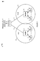
図1は、種々の実施形態に従う例示的無線通信システム100の図である。例示的無線通信システム100は、例えば、トーンホッピングを含むスペクトラム拡散OFDM無線通信システムのような、例示的マルチアクセス直交周波数分割多重化(OFDM)無線通信システムである。例示的無線通信システム100は、複数の基地局(基地局1:102、…、基地局M:104)を含んでおり、該基地局(102,104)は、それぞれ対応する無線通信範囲(セル1:106、セルM:108)を有している。システム100はまた、それぞれネットワークリンク(112,114)を介して基地局(BS1:102、BSM:104)に結合されたネットワークノード110を含んでいる。ネットワークノード110、例えばルータは、ネットワークリンク116を介して他のネットワークノード、例えば他の基地局、ルータ、AAAノード、ホームエージェントノードなど、および/またはインターネットに結合される。ネットワークリンク(112,114,116)は、例えば光ファイバーリンク、ワイヤケーブルリンク、および/またはマイクロ波のような無線リンクであってよい。
FIG. 1 is an illustration of an example
システム100はまた、複数の無線端末、例えばモバイルノードを含んでいる。該モバイルノードは、通信システム100の全体に亘って移動してよく、また現在それが位置しているエリア内の基地局との無線通信リンクを樹立してよい。複数の無線端末(WT1:118…、WTN:120)は、それぞれ無線リンク(122,124)を介して基地局1:102に結合されるように示されている。同様に、複数の無線端末(WT1’:126…、WTN’:128)は、それぞれ無線リンク(130,132)を介して基地局M:104に結合されるように示されている。
当該システムにおける無線端末は、種々の動作モード、例えばOFF、スリープ、保留、1型オン状態、2型オン状態、または3型オン状態であってよい。この例示的実施形態において、無線端末はトラヒックチャンネルセグメントを割当てられることができる一方、他の動作モード、例えばオフ、スリープ、保留モードにおいては、トラヒックチャンネルセグメントを割当てられない。この例示的実施形態において、無線端末には、異なるレベルの幾つかの型のエアリンク資源、例えば、当該無線端末が動作しているオン状態のタイプの関数として、アップリンク専用制御チャンネルセグメントおよび/またはダウンリンク無線端末電力制御セグメントが配分される。この例示的実施形態において、基地局に割当てられた無線端末識別子および対応するオン状態マスクを含む状態遷移メッセージが、無線端末に配分される少なくとも幾つかの資源を同定するために、当該無線端末に通信される。
The wireless terminal in the system may be in various operating modes, such as OFF, sleep, hold,
種々の実施形態は、セル当たり1以上のセクター、例えばセル当たり2、3または4以上のセクターを含んでよい。例えば、一つの例示的実施形態において、基地局は三つのセクターを含み、各セクターは1以上の取付け点を含み、各取付け点はアップリンク/ダウンリンクトーンブロック対に対応する。幾つかの斯かる実施形態において、基地局は取り付け点当たりのベースで資源を配分してよい。 Various embodiments may include one or more sectors per cell, eg, 2, 3 or 4 or more sectors per cell. For example, in one exemplary embodiment, the base station includes three sectors, each sector includes one or more attachment points, and each attachment point corresponds to an uplink / downlink tone block pair. In some such embodiments, the base station may allocate resources on a per-attachment point basis.
幾つかの実施形態は、単一の基地局と、該基地局の資源について競合する複数の無線端末を含んでいる。このような幾つかの実施形態では、単一の基地局が帰路ネットワークに結合される一方、他の実施形態においては、単一の基地局は帰路ネットワークに結合されない。 Some embodiments include a single base station and multiple wireless terminals competing for the base station's resources. In some such embodiments, a single base station is coupled to the return network, while in other embodiments, a single base station is not coupled to the return network.
図2は、種々の実施形態に従って実施される例示的基地局200の図である。例示的基地局200は、図1の例示的システム100における例示的基地局(102,104)の1つであってよい。例示的基地局200は、受信機モジュール202、送信機モジュール204、プロセッサ206、I/Oインターフェース208、およびその上で種々の素子がデータおよび情報を交換してよいバス212を介して一緒に結合されたメモリー210を含んでいる。
FIG. 2 is an illustration of an
メモリー210は、ルーチン218およびデータ/情報220を含んでいる。プロセッサ206、例えばCPUはルーチン218を実行し、またメモリー210の中のデータ/情報を使用して基地局200の動作を制御し、方法を実施する。
受信機モジュール202、例えばOFDM受信機は受信アンテナ203に結合され、該アンテナを介して基地局200は無線端末300からのアップリンク信号を受信する(図3参照)。受信機モジュール202は、受信された信号の少なくとも幾つかを復号するための復号器214を含んでいる。受信されたアップリンク信号は、登録要求信号、状態の変化のための請求、専用の制御チャンネルセグメント信号、およびアップリンクトラヒックチャンネルセグメント信号を含んでいる。専用制御チャンネルセグメント信号は、マルチパート資源割当てメッセージを介して先に基地局によって配分された資源、例えば専用制御チャンネルセグメントを使用して通信される。
A
送信機モジュール204、例えばOFDM送信機は送信アンテナ205に結合され、該送信アンテナを介して、基地局はダウンリンク信号を無線端末300へと送信する。送信機モジュール204は、少なくとも幾つかのダウンリンク信号を符号化するための符号化器216を含んでいる。ダウンリンク信号は、ビーコンおよび/またはパイロットチャンネル信号のような同期信号、状態遷移メッセージ信号、無線端末電力制御セグメント信号、割当て信号を含むトラヒック制御チャンネル信号、およびダウンリンクトラヒックチャンネルセグメント信号を含んでいる。この例示的実施形態においては、状態遷移メッセージ信号は、無線端末に複数の異なるオン状態動作の一つへと命令する状態遷移メッセージを含んでおり、例えばマルチパート資源割当てメッセージは、割当てられる資源を同定する第一の部分と、該マルチ−パート資源割当てメッセージが向けられている無線端末に配分される前記資源の一部を指示する第二の部分を含んでいる。
A
I/Oインターフェース208は、基地局200を他のネットワークノード、例えば他の基地局、AAAノード、ホームエージェントノード、ルータ、コンテンツサーバ等、および/またはインターネットに結合する。I/Oインターフェース208は、基地局200を帰路ネットワークに結合することによって、基地局200取付け点を使用する無線端末が、異なる基地局の無線取付け点を使用するピアノードとの通信セッションに参加することを可能にする。
The I /
ルーチン218は、通信ルーチン222および基地局制御ルーチン224を含んでいる。通信ルーチン222は、基地局200によって使用される種々の通信プロトコルを実施する。基地局プロトコルルーチン224は、状態遷移メッセージモジュール226、専用制御チャンネル信号復旧モジュール228、無線端末電力制御モジュール230、スケジューリングモジュール232、割当て信号発生モジュール234、ダウンリンクトラヒックチャンネルモジュール236、アップリンクトラヒックチャンネルモジュール238、およびトーンホッピングモジュール289を含んでいる。
The routine 218 includes a
状態遷移メッセージモジュール226は、無線端末に対して、複数のオン状態動作の一つを指令する種々の状態遷移メッセージを発生する。モジュール226によって発生される斯かる状態遷移メッセージの一つはマルチパート資源割当てメッセージであり、該メッセージは割当てられる資源を同定する第一の部分と、該マルチパート資源割当てメッセージが向けられる無線端末に配分される資源の一部を同定する第二の部分を含んでいる。状態遷移メッセージモジュール226は、オン状態識別子副モジュール240およびマスク副モジュール242を含んでいる。オン状態識別子副モジュール240は、前記マルチパート資源割当てメッセージにおける第一の部分として含めるためのオン状態識別子を決定する。マスク副モジュール242は、前記マルチパート資源割当てモジュールにおける第二の部分として含められるべきオン状態マスクを決定する。副モジュール240および242は、基地局において現在利用可能な資源を考慮した特定のマルチパート資源割当てメッセージ、無線端末要求情報、無線端末要件、無線端末サービスレベル情報および/または基地局資源配分ポリシーについて、それらの決定を行う。 The state transition message module 226 generates various state transition messages that command one of a plurality of on-state operations to the wireless terminal. One such state transition message generated by module 226 is a multipart resource assignment message, which is a first part identifying the assigned resource and to the wireless terminal to which the multipart resource assignment message is directed. It includes a second part that identifies some of the resources to be allocated. The state transition message module 226 includes an on-state identifier submodule 240 and a mask submodule 242. The on-state identifier submodule 240 determines an on-state identifier to include as the first part in the multipart resource assignment message. The mask submodule 242 determines an on-state mask to be included as the second part in the multipart resource allocation module. Sub-modules 240 and 242 may be configured for specific multipart resource allocation messages, wireless terminal request information, wireless terminal requirements, wireless terminal service level information and / or base station resource allocation policies that take into account resources currently available at the base station. Make those decisions.
DCCH信号復旧モジュール228は、制御情報レポート、例えばアップリンクトラヒック要求レポート、SNRレポート、ノイズレポート、干渉レポート、電力利用可能性レポート等を、配分された資源部分を使用して無線端末から通信された受信信号から再生させるが、該配分された部分は先に通信されたマルチパート資源割当てメッセージにおける情報によって指示されている。例えば、前記資源の配分された部分は、再帰アップリンクチャンネル構造における信号論理専用制御チャンネルトーンに対応する一組の専用の制御チャンネルセグメントであり、無線端末のための特定の組は、基地局に割当てられた無線端末オン識別子および無線端末に現在割当てられた関連のオン状態マスクの関数である。
DCCH
無線端末電力制御モジュール230は、無線端末送信電力制御のためのコマンド制御指令、例えば、予め定められた量、利得因子または調節によって無線端末送信電力レベルを増分または減分するコマンドを発生する。無線端末電力制御モジュール230は、現在無線端末に割当てられているオン状態識別子および対応するオン状態マスク値、並びに個々のセグメントをオン状態識別子およびマスク値の組合せにリンクさせる再帰ダウンリンク構造情報を使用することにより、特定のダウンリンク無線端末電力制御セグメントが現在特定の無線端末と関連していることを認識する。
The wireless terminal
スケジューリングモジュール232、例えばスケジューラは、アップリンクおよびダウンリンクトラヒックチャンネルセグメントを、基地局のスケジューリングポリシーに従って無線端末にスケジュール化する。スケジューリングモジュール232は、割当を決定するに際して、オン状態識別子および対応するオン状態マスク情報を使用する。何故なら、特定の無線端末に割当てられ得る番号および特定のトラヒックチャンネルセグメントは、当該無線端末に関連して現在割当てられているオン状態マスクの関数として決定されるからである。この例示的実施形態において、無線端末が111のオン状態マスクを有しているならば、該無線端末は、潜在的に何れかのアップリンクまたはダウンリンクトラヒックチャンネルセグメントを割当てられることができる。もし、無線端末が001、010または100のオン状態マスクを有していれば、基地局は、当該無線端末に少なくとも幾つかのトラヒックチャンネルセグメントを割当てることを妨げられる。もし、無線端末が011,110または101のオン状態マスクを有していれば、基地局は、当該無線端末が001、010または100のオン状態マスクを有しているときよりも、当該無線端末に対する潜在的な割当てのために利用可能なより多くのトラヒックチャンネルセグメントを有している。
A
割当て信号発生モジュール234は、トラヒックチャンネル割当て信号を発生する。該トラヒックチャンネル割当て信号は、ダウンリンクトラヒック制御チャンネルエアリンク資源を使用して通信される。割当て信号発生モジュール234は、少なくとも幾つかの割当て信号の中にオン状態マスク識別子情報、例えば単一ビット識別子を組込む。種々の実施形態において、トラヒックチャンネル割当てに含められたオン状態マスク識別子情報のビット数は、オン状態マスクのビット数よりも少なく、例えば1ビット対3ビットである。 The assignment signal generation module 234 generates a traffic channel assignment signal. The traffic channel assignment signal is communicated using a downlink traffic control channel air link resource. The assignment signal generation module 234 incorporates on-state mask identifier information, eg, a single bit identifier, in at least some assignment signals. In various embodiments, the number of bits of on-state mask identifier information included in the traffic channel assignment is less than the number of bits of the on-state mask, for example, 1 bit to 3 bits.
ダウンリンクトラヒックチャンネルモジュール236は、ダウンリンクトラヒックチャンネルセグメント信号を通信することに関連した動作、例えば、特定の無線端末を目的としたユーザデータを、該特定の無線端末に割当てられたセグメント上で通信されるべき信号の中に組込むことを実行する。アップリンクトラヒックチャンネルセグメントモジュール236は、アップリンクトラヒックチャンネルセグメント信号を処理すること、および該復旧された信号を当該セグメントが割当てられている適切な無線端末に関連させることを含む動作を実行する。 Downlink traffic channel module 236 communicates operations associated with communicating downlink traffic channel segment signals, eg, user data intended for a particular wireless terminal, on a segment assigned to that particular wireless terminal. Incorporate into the signal to be done. Uplink traffic channel segment module 236 performs operations including processing the uplink traffic channel segment signal and associating the recovered signal with the appropriate wireless terminal to which the segment is assigned.
トーンホッピングモジュール238は、アップリンクおよびダウンリンクトーンホッピングを実行するために、トーンホッピング情報281を含むデータ/情報220を使用する。トーンホッピングモジュール238は、論理チャンネルトーンを、送信のために使用される物理的トーンにマッピングする。トーンホッピングモジュール238は、異なるレートでホップし、またアップリンクおよびダウンリンクトーンホッピングについて異なるホッピングシーケンスを使用する。例えば、放送ストリップチャンネルセグメント間隔を除く連続するOFDMシンボルの各々の上で、第一のトーンホッピングシーケンスに従ってダウンリンクトーンホッピングを行い、またアクセスセグメント間隔を除く休止ベースで、第二のトーンホッピングシーケンスに従ってアップリンクトーンホッピングを行う。例えば、ここでの休止は、例えば7つの連続するOFDMシンボル送信時間である。説明した資源配分特徴と共にトーンホッピングを使用することは、非常に有利である。何故なら、それは当該基地局を使用する種々の無線端末が経験する干渉レベル、およびノイズレベルをバランスさせるように働くからである。従って、ノイズおよび/または干渉の観点から見て、問題のある単一の物理的トーンは、情報、例えば制御情報の通信に苛酷に影響しない。例えば、単一の論理専用制御チャンネルトーンを利用して無線端末に配分された一組の専用制御チャンネルセグメント資源は、トーンホッピングを利用することによって干渉を分布させ、および/または単一のトーンに対する高干渉レベルおよび/または劣悪な条件の影響を減少させるように働くことができる。
データ/情報220は、システムデータ/情報244、複数組の状態遷移メッセージ情報(状態遷移メッセージ1情報248、…、状態遷移メッセージn情報250)、複数の割当てメッセージ情報(割当てメッセージ1情報252、…、割当てメッセージN情報254)、複数の電力制御メッセージ情報(電力制御メッセージ1情報256、電力制御メッセージN情報258)、複数の専用制御チャンネルセグメント情報(DCCHセグメント1情報260、…、DCCHセグメントN情報262)、および無線端末データ/情報264を含んでいる。
The data /
システムデータ/情報244は、ダウンリンク/アップリンクタイミング/周波数構造情報246、およびモード情報247を含んでいる。図5は、例示的なダウンリンクおよびアップリンクの周波数構造情報を示している。DL/ULタイミング/週波数構造情報246は、アップリンク専用制御チャンネル情報266、ダウンリンク無線端末電力制御チャンネル情報270、ダウンリンクトラヒック制御チャンネルを、ダウンリンクトラヒックチャンネルに関連付ける情報274、ダウンリンクトラヒック制御チャンネルをアップリンクトラヒックチャンネルに関連付ける情報278、およびトーンホッピング情報281を含んでいる。UL・DCCHチャンネル情報266は、無線端末オン状態識別子/専用制御チャンネルトーン情報267および無線端末オンマスク情報268、例えば、基地局が使用している再帰チャンネル構造における専用制御チャンネルセグメントに関連したオンマスクビットパターンを同定する情報を含んでいる。図6および対応する説明は、例示的な情報267および268を記載している。DL・WT電力制御チャンネル情報270は、無線端末オン状態識別子/セグメント組アソシエーション情報271および無線端末オンマスク情報272、例えば、基地局が使用している再帰チャンネル構造におけるダウンリンク電力制御チャンネルセグメントに関連したオンマスクビットパターンを同定する情報を含んでいる。図7および対応する説明は、例示的な情報271および272を記載している。ダウンリンクトラヒック制御チャンネルをダウンリンクトラヒックチャンネルに関連付ける情報274は、無線端末オンマスク情報276、例えば、何れの無線端末オンマスクが何れの割当てスロットに関連付けられるか、何れの無線端末オンマスクが何れのダウンリンクトラヒックチャンネルセグメントに関連付けられるかを同定する情報、および割当てマスク識別子情報を含んでいる。図8および対応するテキストは、幾つかの例示的情報276を記述している。ダウンリンクトラヒック制御チャンネルをアップリンクトラヒックチャンネルに関連付ける情報278は、無線端末オンマスク情報280、例えば、何れの無線端末オンマスクが何れの割当てスロットに関連付けられるか、何れの無線端末オンマスクが何れのアップリンクトラヒックチャンネルセグメントに関連付けられるかを同定する情報、および割当てマスク 識別子情報を含んでいる。図9および対応するテキストは、幾つかの例示的な情報280を記述している。トーンホッピング情報281は、アップリンク論理チャンネルトーンをアップリンク物理的トーンにマップするために使用されるアップリンクトーンホッピング情報、およびダウンリンク論理チャンネルトーンをダウンリンク物理的トーンにマップするために使用されるダウンリンクトーンホッピング情報を含んでいる。
System data /
モード情報247は、フルトーンフォーマットDCCHモード情報249、1/3分割トーンフォーマットDCCHモード情報251、および2/3分割トーンフォーマットDCCHモード情報253を含んでいる。フルトーンフォーマットDCCHモード情報249は、111のオン状態ビットマスクパターンを、フルトーンフォーマットDCCHモードのオン状態動作、例えば資源配分の高い状態に関連付ける情報を含んでいる。1/3分割トーンフォーマットDCCHモード情報251は、001、010および100のオン状態ビットマスクパターンを、1/3分割トーンフォーマットDCCHモードのオン状態動作、例えば資源配分の低い状態に関連付ける情報を含んでいる。2/3分割トーンフォーマットDCCHモード情報253は、110、101および011のオン状態ビットマスクパターンを、2/3分割トーンフォーマットDCCHモードのオン状態動作、例えば資源配分の中間の状態と関連付ける情報を含んでいる。
状態遷移メッセージ1情報248は、ある状態遷移メッセージの情報、例えば、無線端末に向けられて該無線端末を複数のオン状態動作の1つへと命令し、且つ該無線端末が使用するための再帰チャンネル構造の中に専用資源を配分する、マルチパート資源割当てメッセージを含んでいる。この状態遷移メッセージは、状態遷移メッセージモジュール226によって発生される。割当てメッセージ1情報252は、割当てメッセージにおける情報、例えば、1以上のトラヒックチャンネルスロット割当てを運ぶトラヒック制御チャンネルメッセージを含み、該メッセージは信号発生モジュール234によって発生される。図13および図14は幾つかの例示的なトラヒックチャンネル割当て信号伝達を示している。電力制御メッセージ1情報256は、無線端末送信電力コマンド信号伝達情報を含んでいる。DCCHセグメント1情報260は、専用制御セグメントにおいて通信される情報、例えば、DCCH信号復旧モジュール228によって処理されるべき情報を含んでいる。
The
無線端末データ/情報264は、複数組の無線端末データ/情報(WT・1データ/情報282,…,WT・Nデータ/情報284)を含んでいる。WT・1データ/情報282は、オン状態識別子286、割当てられたWTオンマスク288、専用制御チャンネルモード290、基地局取付け点情報292、電力コマンド情報293、ユーザ/デバイス/セッション/資源情報294、復旧されたDCCHレポート情報296、割当てられたトラヒックチャンネルセグメント情報297、およびユーザデータ298を含んでいる。WTオン状態識別子286は、現在WT1に関連付けられているオン状態識別子であるのに対して、割当てられたWTオンマスク288は、現在WT1に関連付けられている対応するオンマスクである。基地局200は、オン状態識別子および対応するオンマスクを、利用可能な資源から無線端末へと配分する。図4は、例示的実施形態についてのオン状態識別子およびマスクの潜在的な配分を示している。図10もまた、オン状態識別子および対応するマスクの幾つかの例示的無線端末への例示的配分を示している。
The wireless terminal data /
DCCHモード290は、オン状態識別子および割当てられた無線端末オンマスク288に従うWT1の専用制御チャンネルモードの動作、例えば、フルトーンフォーマットDCCHモード、1/3分割トーンフォーマットDCCHモードおよび2/3分割トーンフォーマットDCCHモードのうちの1つを同定する。基地局取付け点情報292は、WT1がその現在のネットワーク取付け点として使用しているセクターおよび/またはトーンブロックを同定する。電力コマンド情報293は、無線端末送信電力制御コマンド、例えば、一つのステップ、予め定められた量、または予め定められた利得調節に従った増分もしくは減分の送信電力レベルを含んでいる。WT1293のための電力コマンド情報が電力制御メッセージに組込まれ、WT1に配分されたセグメントにおいて通信される。幾つかの実施形態において、電力制御メッセージは単一のOFDM変調シンボルを介して通信される。復旧されたDCCHセグメント情報296は、DCCH信号復旧モジュール228の出力であり、例えばアップリンクトラヒックチャンネル要求情報、ビーコム比率レポート情報、信号/ノイズ比レポート情報、自生雑音レポート情報、および無線端末送信電力レポート情報を含んでいる。割当てられたトラヒックチャンネルセグメント情報297は、トラヒックチャンネル割当てメッセージ、例えばメッセージ252において通信されるのに適した割当て情報を含んでいる。ユーザデータ376は、例えば、無線端末に割当てられたアップリンクおよび/またはダウンリンクトラヒックチャンネルセグメントにおいて通信されるトーン、オーディオ、データ、画像データ、テキストデータ、ファイルデータ等を含んでいる。
DCCH mode 290 operates in WT1 dedicated control channel mode according to the on-state identifier and assigned wireless terminal on-mask 288, eg, full tone format DCCH mode, 1/3 split tone format DCCH mode and 2/3 split tone format DCCH mode. One of the is identified. Base station
図3は、例示的な無線端末300、例えば種々の実施形態に従って実施されるモバイルノードの図である。例示的無線端末300は、図1のシステムにおける無線端末(118120,126,128)の何れかであってよい。例示的無線端末300は、受信機モジュール302、送信モジュール304、プロセッサ306、ユーザI/O装置308、およびバス312を介して一緒に結合されたメモリー310を含んでおり、前記バス312の上で種々の素子がデータおよび情報を交換してよい。
FIG. 3 is an illustration of an
メモリー310は、ルーチン318およびデータ/情報320を含んでいる。プロセッサ306、例えばCPUはルーチン318を実行し、メモリー310の中のデータ/情報320を使用して無線端末300の動作を制御し、方法を実行する。
受信機モジュール302、例えばOFDM受信機は受信アンテナ303に結合され、該アンテナを介して、無線端末300は基地局200からダウンリンク信号を受信する。受信機モジュール302は、受信されたダウンリンク信号の少なくとも幾つかを復号するための復号器314を含んでいる。受信されたダウンリンク信号は、ビーコンおよび/またはパイロットチャンネル信号のようなタイミング/同期信号、状態遷移メッセージ信号、電力制御チャンネルセグメント信号、トラヒック制御チャンネル割当て信号、およびダウンリンクトラヒックチャンネルセグメント信号を含んでいる。この例示的実施形態において、状態遷移メッセージ信号は、無線端末に対して複数の異なるオン状態動作の一つへと命令する状態遷移メッセージ、例えばマルチパート資源割当てメッセージを含んでおり、これは割当てられる資源を同定する第一の部分、および該マルチパート資源割当てメッセージが向かう無線端末に配分される前記資源の一部を指示する第二の部分を含んでいる。
A
送信モジュール304、例えばOFDM送信機は送信アンテナ305に結合され、該アンテナを介して、無線端末300は基地局200へとアップリング信号を送信する。送信モジュール304は、アップリング信号の少なくとも幾つかを符号化するための符号化器316を含んでいる。幾つかの実施形態では、例えば二重通信モジュールに関連して、受信機および送信機のために同じアンテナが用いられる。アップリンク信号には、登録要求信号、状態の変化の要求、専用制御チャンネルセグメント信号およびトラヒックチャンネルセグメント信号が含まれる。
A
ユーザI/O装置308、例えばマイクロホン、キーパッド、キーボード、スイッチ、カメラ、スピーカ、ディスプレー等は、無線端末300のユーザが、データ/情報を入力し、出力データ/情報にアクセスし、アプリケーションを制御し、無線端末の少なくとも幾つかの機能を制御すること、例えば通信セッションを開始することを可能にする。
User I /
ルーチン318は、通信ルーチン332および無線端末制御ルーチン324を含んでいる。通信ルーチン332は、無線端末300によって使用される種々の通信プロトコルを実行する。無線端末制御ルーチンは、状態遷移モジュール326、資源配分決定モジュール332、オンモード決定モジュール333、専用制御チャンネルモジュール334、無線端末送信電力制御モジュール336、トラヒックチャンネル割当て決定モジュール338、ダウンリンクトラヒックチャンネルモジュール340、アップリンクトラヒックチャンネルモジュール342、およびトーンホッピングモジュール343を含んでいる。
The routine 318 includes a
状態遷移メッセージモジュール326は、オン状態識別子および対応するオン状態マスクを含んだマルチパート資源割当てメッセージを含む受信された遷移状態メッセージを処理する。状態遷移モジュール326は、オン状態識別子副モジュール328およびオン状態マスク副モジュール330を含んでいる。オン状態識別子副モジュール328は、無線端末に現在割当てられる基地局により割当てられた無線端末オン状態識別子354、例えば5ビットフィールドにおいて通信される1…31の範囲の値を復旧する。マスク副モジュール330は、基地局により割当てられた無線端末オン状態マスク356、例えば、3ビットフィールドを介して通信される111、001、010、100、110、101および011のうちの一つを復旧する。該復旧されたオン状態識別子および対応するマスクは、例えば、基地局および無線端末の両者に知られた再帰チャンネルアップリンクおよび/またはダウンリンク構造において、配分される資源を決定するために無線端末によって使用されることを意図したものである。加えて、該復旧されたオン状態識別子および対応するマスクは、オン状態モードの動作を決定するため、および無線端末に関連したトラヒックチャンネル割当てを決定するために、当該無線端末によって使用されることを意図したものである
オンモード決定モジュール333は、割当てられた無線端末オンマスク356およびモード情報399を使用して動作のオン状態モードを決定し、該モードにおいて無線端末は、例えば次のように動作される:割当てられたWTオンマスク=111であれば、当該該無線端末はフルトーンフォーマットDCCH動作モードで動作される;WTオンマスクが001、010および100のうちの1つであれば、当該無線端末は1/3分割トーンフォーマットDCCH動作モードで動作される;割当てられたWTオンマスクが110、011および101のうちの1つであれば、当該無線端末は2/3分割トーンフォーマットDCCH動作モードで動作される。DCCHモード情報358は、オンモード決定モジュール333の出力である。
The state transition message module 326 processes the received transition state message including a multipart resource assignment message that includes an on-state identifier and a corresponding on-state mask. The state transition module 326 includes an on-
資源配分決定モジュール332は、割当てられた資源および該資源の配分された部分を、オン状態識別子354および割当てられた無線端末オンマスク356の関数として決定する。無線端末361に配分された同定された資源は、モジュール332の出力である。無線端末361に割当てられた同定された資源は、ダウンリンクに配分された資源情報363およびアップリンクに配分された資源情報365を含んでいる。ダウンリンクに配分される資源情報363は、一組の無線端末電力制御セグメントを同定する情報、および再帰ダウンチャンネル構造を備えた前記組の一部を同定する情報を含んでいる。例えば、割当てられた資源を表すダウンリンクセグメントの前記組は無線端末オン状態識別子=2に関連した図7における三つのセグメント組であることを考慮し、また、WTは図12に関してはWT・B(オンマスク=001)であり、配分されたダウンリンク資源はセグメント1218を含むことを考慮する。アップリンク配分された資源情報36は、アップリング専用制御チャンネルトーン、および再帰アップリンクチャンネル構造内の無線端末に配分された配分されたアップリンク専用制御チャンネルセグメント組を同定する情報を含んでいる。例えば、図11のトーン82(これは基地局に割当てられた無線端末音状態識別子=2に対応する)は、割当てられたアップリンク資源を表すことを考慮し、また該無線端末がWT・Bであることを考慮すれば、配分された資源はカラム1112、1118および1124の時間間隔、或いはアップリンク専用制御チャンネルセグメント[2][0]、セグメント[2][3]およびセグメント[2][6]の間のトーン82に対応する。
The resource
専用制御チャンネルモジュール334は、種々のアップリンクレポートを発生し、また該レポートを運ぶ専用制御チャンネルセグメント信号を発生し、該レポートは前記音状態識別子354およびオン状態マスク356に対応する配分された専用制御チャンネルセグメントを使用して通信される。モジュール334によって発生された例示的レポートは、アップリンクトラヒック要求レポート、干渉レポート、ノイズレポート、送信電力レポート、およびSNRレポートを含んでいる。
The dedicated
無線端末送信電力制御モジュール336は、該無線端末に配分されたダウンリンク資源(例えばオン状態識別子354およびオン状態マスク356に従って該無線端末に配分されたセグメント)を介して通信され、該無線端末に向けられた受信された電力制御コマンドを処理する。無線端末送信電力制御モジュール336は、送信モジュール304を制御して、復旧されたコマンドに従った調節を行う。
The wireless terminal transmission power control module 336 is communicated via downlink resources allocated to the wireless terminal (eg, segments allocated to the wireless terminal according to the on-state identifier 354 and the on-state mask 356), and is transmitted to the wireless terminal. Process directed received power control commands. The wireless terminal transmission power control module 336 controls the
トラヒックチャンネル割当て決定モジュール338は、その現在割当てられているオン状態識別子354および対応する割当てられたオンマスク356が与えられれば、何れのトラヒックチャンネルセグメントが当該無線端末に割当てられ得るかを決定する。モジュール338はまた、何れのトラヒックチャンネルセグメントが当該無線端末に割当てられるかを決定する。この例示的実施形態では、割当てスロットと対応するトラヒックチャンネルセグメントとの間に、固定された予め定められた関係が存在する。モジュール338は、種々の動作を実行する際に、割当てられたオン状態識別子354、割当てられたオンマスク356、ダウンリンクトラヒック制御チャンネルをダウンリンクトラヒックチャンネル388に関連させる情報、および/またはダウンリンクトラヒック制御チャンネルをアップリンクトラヒックチャンネル392に関連させる情報を使用する。例えば、幾つかの割当てスロットは、オン状態マスクの関数として利用可能ではない。もう一つの例として、トラヒックチャンネル割当ては、オンマスク識別子、例えば、トラヒックチャンネルセグメントと関連し得る二つの異なるオン状態ビットマスク間を識別する単一ビットを含んでいる。
Traffic channel assignment determination module 338 determines which traffic channel segments can be assigned to the wireless terminal given its currently assigned on-state identifier 354 and a corresponding assigned on-mask 356. Module 338 also determines which traffic channel segments are assigned to the wireless terminal. In this exemplary embodiment, there is a fixed predetermined relationship between the assigned slot and the corresponding traffic channel segment. Module 338 may perform various operations as assigned on-state identifier 354, assigned on-mask 356, information relating downlink traffic control channel to
ダウンリンクトラヒックチャンネルモジュール340は、当該無線端末に割当てられているトラヒックチャンネルセグメント上を通信された、受信されたトラヒックチャンネルセグメント信号からユーザデータを復旧する。アップリンクトラヒックチャンネルモジュール342は、当該無線端末に割当てられているアップリングトラヒックチャンネルセグメント上で通信されるアップリンクトラヒックチャンネルセグメント信号を発生する。
トーンホッピングモジュール343は、トーンホッピング情報301を含むデータ/情報320を使用して、アップリンクおよびダウンリンクトーンホッピングを実施する。トーンホッピングモジュール343は、論理チャンネルトーンを、送信に使用される物理的トーンにマップする。トーンホッピングモジュール343は異なるレートでホップし、またアップリンクおよびダウンリンクトーンホッピングのために異なるホッピングシーケンスを使用し、例えば、放送ストリップチャンネルセグメント間隔以外の連続するOFDMシンボルに対して、第一のトーンホッピングシーケンスに従ってダウンリンクトーンホッピングを行い、またアクセスセグメント間隔を除く休止ベースで、トーンホッピングシーケンスに従ってアップリンクトーンホッピングを実施し、ここでの休止は、例えば連続するOFDMシンボル送信時間である。説明した資源配分特徴に関連してトーンホッピングを使用することは、当該基地局を使用する種々の無線端末が経験する干渉レベルおよびノイズレベルをバランスさせる方向に作用するので、非常に有利である。従って、ノイズおよび/または干渉の観点から、問題のある単一の物理的トーンは、無線端末300のための情報、例えば制御情報に対して過酷な影響は与えない。例えば、一組の制御チャンネルセグメント資源は、一つの論理専用制御チャンネルトーンに対応する無線端末300に配分され、また無線端末300はトーンホッピングを利用することにより、干渉を分布させ、および/または高い干渉レベルおよび/または劣悪な条件の単一の物理的トーンに対する影響を低減するように働くことができる。
The downlink traffic channel module 340 recovers user data from the received traffic channel segment signal communicated on the traffic channel segment assigned to the wireless terminal. The uplink
データ/情報320は、ユーザ/装置/セッション/資源情報344、システムデータ/情報346、受信された状態遷移メッセージ情報352、基地局取付け点情報353、オン状態識別子354、割当てられたWTオンマスク356、動作の専用制御チャンネルモード358、無線端末に配分された同定された資源361、複数の受信された電力制御メッセージ(受信された電力制御メッセージ1情報362、…、受信された電力制御メッセージN情報364)、複数の専用制御チャンネルセグメント組の情報(専用制御チャンネルセグメント1情報366、…、専用制御チャンネルセグメントN情報368)、複数組の受信された割当てメッセージ情報(受信された割当てメッセージ1情報370、…、受信された割当てメッセージN情報372)、割当てられたトラヒックチャンネルセグメント情報374、およびユーザデータ376を含んでいる。
Data /
ユーザ/装置/セッション/資源情報344は、装置同定情報、同定情報、ピアノード情報を含む進行中の通信セッション情報、ルーティング、アドレッシング情報、および種々のセッション状態情報を含んでいる。受信された状態遷移メッセージ情報352は、マルチパート資源割当てメッセージに対応異する情報を含んでいる。受信された状態遷移メッセージ情報352は、状態遷移モジュール326に入力される情報を含んでいる。基地局取付け点情報353は、当該無線端末がその現在のネットワーク結合点として使用している基地局を同定する情報、例えば、基地局識別子情報、基地局セクター識別子情報、基地局キャリア周波数情報、および/または基地局トーンブロック同定情報を含んでいる。オン状態識別子354は、状態遷移メッセージによって通信され、オン状態識別子副モジュール328によって決定される基底状態割当て無線端末オン状態識別子、例えば1…31の値、即ち、再帰チャンネル構造における種々の通信資源に関連付けられるべき暫定的に割当てられた識別子である。該無線端末はまた、追加の基地局割当て識別子、例えば登録されたユーザ識別子および/または基地局割当てのアクティブユーザ識別子を有しており、これらはユーザがトラヒックチャンネルセグメントを割当てられることができない動作状態、例えばホールド状態、スリープ状態等のような他の動作モードに関連している。割当てられたオン状態マスク365は、状態遷移メッセージにおいて通信され且つマスク副モジュール330によって決定される、基地局割当てのオン状態マスク、例えば、111、001、100、010、110、101および011のうちの一つ、即ち、割当てられた資源の配分された部分を決定すること含む動作のために使用される暫定的に割当てられたマスクである。DCCHモード358、例えば、フルトーンフォーマットモード、1/3分割トーンフォーマットモード、および2/3分割トーンフォーマットモードのうちの一つは、オンモード決定モジュール333の出力である。
User / device / session /
無線端末361に配分された同定された資源は、資源配分決定モジュール332の出力である。無線端末361に配分された同定された資源は、ダウンリンク資源配分情報363、例えば、当該無線端末に配分されたダウンリンク無線端末制御チャンネルセグメント、およびアップリンク資源配分情報365、例えば、当該無線端末に割当てられたアップリンク専用制御チャンネル論理トーン、および当該無線端末に配分された専用制御セグメントを同定する情報を含んでいる。
The identified resource allocated to the
受信された電力制御メッセージ情報362は、送信機304を調節するために使用される、無線端末電力制御モジュール336に入力される情報およびモジュール336から出力される情報を含んでいる。DCCHセグメント1情報366は情報、例えばレポート情報、および当該無線端末に配分されたDCCHセグメントにおいて通信される発生された信号を含んでいる。
Received power
受信された割当てメッセージ1情報370は、モジュール338によって処理されるトラヒック制御チャンネルメッセージに対応する情報を含んでいる。割当てられたトラヒックチャンネルセグメント情報374は、トラヒックチャンネル割当て決定モジュール338の出力であり、当該無線端末に現在割当てられている再帰アップリンクおよび/またはダウンリンクトラヒックチャンネル構造におけるトラヒックチャンネルセグメントを同定する情報を含んでいる。ユーザデータ374は、例えば、トーン、オーディオ、データ、画像データ、テキストデータ、ファイルデータ等を含んでおり、当該無線端末に割当てられたアップリンクおよび/またはダウンリンクトラヒックチャンネルセグメントにおいて通信される。
Received
システムデータ/情報346は、複数組の基地局データ/情報(基地局1データ/情報348、…、基地局Mデータ/情報350)およびモード情報399を含んでいる。基地局1データ/情報348は、ダウンリンク/アップリンクタイミング/周波数構造情報378を含んでいる。図5は、例示的なダウンリンクおよびアップリンク周波数構造情報を示している。該DL/ULタイミング/周波数構造情報378は、アップリンク専用制御チャンネル情報380、ダウンリンク無線端末電力制御チャンネル情報384、ダウンリンクトラヒック制御チャンネルをダウンリンクトラヒックチャンネルに関連付ける情報388、ダウンリンクトラヒック制御チャンネルをアップリンクトラヒックチャンネルに関連付ける情報392、およびトーンホッピング情報301を含んでいる。UL・DCCHチャンネル情報380は、無線端末オン状態識別子/専用制御チャンネルトーンアソシエーション情報381および無線端末オンマスク情報382、例えば、当該基地局によって使用されている再帰チャンネル構造における専用制御チャンネルセグメントに関連したオンマスクビットパターンを同定する情報を含んでいる。図6および対応する説明は、例示的な情報381および382を記述している。DL・WT電力制御チャンネル情報384は、無線端末オン状態識別子/ダウンリンク電力制御セグメント組アソシエーション情報385、および無線端末オンマスク情報386、例えば、当該基地局によって使用される再帰チャンネル構造におけるダウンリンク電力制御チャンネルセグメントに関連したオンマスクビットパターンを同定する情報を含んでいる。図7および対応する説明は、例示的な情報385および386を記述している。ダウンリンクトラヒック制御チャンネルをダウンリンクトラヒックチャンネルに関連付ける情報388は、無線端末オンマスク情報390、例えば、何れの無線端末オンマスクが何れの割当てスロットに関連するか、何れの無線端末オンマスクが何れのダウンリンクトラヒックチャンネルセグメントに関連するかを同定する情報、および割当てマスク識別子情報を含んでいる。図8および対応するテキストは、幾つかの例示的な情報390を記述している。ダウンリンクトラヒック制御チャンネルをアップリンクトラヒックチャンネル関連付ける情報392は、無線端末オンマスク情報394、例えば、何れの無線端末オンマスクがた何れの割当てスロットに関連するか、何れの無線端末オンマスクが何れのアップリンクトラヒックチャンネルセグメントに関連するかを同定する情報、および割当てマスク識別子情報を含んでいる。図9および対応するテキストは、幾つかの例示的情報394を記述している。トーンホッピング情報301は、アップリンク論理チャンネルトーンをアップリンク物理的トーンにマップするために使用されるアップリンクトーンホッピング情報、およびダウンリンク論理チャンネルトーンをダウンリンク物理的トーンにマップするために使用されるダウンリンクトーンホッピング情報を含んでいる。
System data /
モード情報399は、フルトーンフォーマットDCCHモード情報397、1/3分割トーンフォーマットDCCHモード情報395、および2/3分割トーンフォーマットDCCHモード情報393を含んでいる。フルトーンフォーマットDCCHモード情報397は、111のオン状態ビットマスクパターンをフルトーンフォーマットDCCHモードのオン状態動作、例えば資源配分の高い状態に関連させる情報を含んでいる。1/3分割トーンフォーマットDCCHモード情報395は、001、010、および100のオン状態ビットマスクパターンを、1/3分割トーンフォーマットDCCHモードのオン状態動作、例えば、資源配分の低い状態に関連させる情報を含んでいる。2/3分割トーンフォーマットDCCHモード情報397は、110、101、および011のオン状態ビットマスクパターンを、2/3分割トーンフォーマットDCCHモードのオン状態動作、例えば資源配分の中間状態に関連させる情報を含んでいる。
図4は、例示的基地局402、例示的な無線端末(無線端末1404、…、無線端末N405)、例示的な状態遷移メッセージ信号伝達(状態メッセージ406、…、状態遷移メッセージ407)、および種々のモードの無線端末動作に関連させる情報を示す図400である。基地局402は、図2の例示的基地局200であってよい一方、無線端末(404、…、405)は、図3の無線端末300であってよい。この例において、状態遷移メッセージ406は、基地局402から無線端末1404へと送られるのに対して、状態遷移メッセージ407は基地局402から無線端末N405へと送られる。状態遷移メッセージ406は、基地局割当て無線端末識別子408、例えば1…31の範囲の5ビットフィールド値、および無線端末オン状態マスク値410、例えば3ビットフィールド値を含んでいる。状態遷移メッセージ407は、基地局割当ての無線端末識別子409、例えば1、…、31の範囲の5ビットフィールド値409、および無線端末オン状態マスク値411、例えば3ビットフィールド値を含んでいる。図400の例において、状態遷移メッセージの無線端末オン識別子フィールドにおける無線端末オン状態識別子の値は、31の専用チャンネルトーン(専用制御チャンネルトーン1412、…、専用制御チャンネルトーン31454)の一つに対応することができる。
FIG. 4 illustrates an
この例では、単一の専用制御チャンネルトーンに対応して、基地局は、(i)1/3分割トーンフォーマットの三つ以下の異なる無線端末を、専用制御チャンネル信号伝達のための時間共有ベースで使用するための同じトーンに、(ii)一つの無線端末に、専用制御チャンネル信号伝達のために専ら使用されるトーンを、または(iii)専用制御チャンネル信号伝達のために時間共有ベースで同じトーンを使用するために、1/3分割トーンフォーマットの一つ以下の無線端末および2/3分割トーンフォーマットの一つ以下の無線端末を、割当てることができる。 In this example, in response to a single dedicated control channel tone, the base station (i) transmits up to three different wireless terminals in 1/3 split tone format to a time-sharing base for dedicated control channel signaling. The same tone for use in (ii) one radio terminal, the tone used exclusively for dedicated control channel signaling, or (iii) the same on a time-sharing basis for dedicated control channel signaling To use tones, one or less wireless terminals of 1/3 split tone format and one or less wireless terminals of 2/3 split tone format can be assigned.
基地局402は、三つの無線端末が専用制御チャンネルトーン1に対応する1/3分割トーンフォーマットで動作することを決定したと考えよう。基地局402は、三つの異なる状態遷移メッセージを三つの異なる無線端末に送る。第一の状態遷移メッセージは、無線端末オン状態識別子=00001:414およびwtOnMask=001:416を含んでいる。第二の状態遷移メッセージは、無線端末オン状態識別子=00001:418およびwtOnMask=010:420を含んでいる。第三の状態遷移メッセージは、無線端末オン状態識別子=00001:422およびwtOnMask=100:424を含んでいる。
Consider that
次に、もう一つの選択肢として、基地局402は、一つの無線端末が専用チャンネルトーン1に対応してフルトーンフォーマットで動作することを決定したと考えよう。該基地局402は、状態遷移 メッセージを、フルトーンフォーマットモードで動作される無線端末に送る。該状態遷移 メッセージは、無線端末オン状態識別子=00001:426およびwtOnMask=111:428を含んでいる。
Next, as another option, consider that
次に、別の選択肢として、基地局402は、専用制御チャンネルトーン1に対応して、一つの無線端末が1/3分割トーンフォーマットで動作し、一つの無線端末が2/3分割トーンフォーマットで動作することを決定したと考えよう。三つの異なる選択肢が可能である。第一の選択肢では、該基地局は、基地局割当ての無線端末識別子=第一の遷移状態メッセージを第一の無線端末に送る。第一の代替例において、基地局は、基地局割当ての無線端末識別子=00001:430およびwtOnMask=001:432を含む第一の状態遷移メッセージを第一の無線端末に送り、また基地局割当ての無線端末識別子=00001:434およびwtOnMask=110:436を含む第二の状態遷移メッセージを、第二の無線端末へと送る。第二の代替例において、該基地局は、基地局割当ての無線端末識別子=00001:438およびwtOnMask=010:440を含む第一の状態遷移体メッセージを第一の無線端末へと送り、また基地局割当ての無線端末識別子00001:442およびwtOnMask=101:444を含む第二の状態遷移メッセージを第二の無線端末へと送る。第三の代替例では、該基地局は、基地局割当てによる無線端末識別子=00001:446およびwtOnMask=100:448を含む第一の状態遷移メッセージを第一の無線端末へと送り、また基地局割当てによる無線端末識別子=00001:450およびwtOnMask=011:452を含む第二の状態遷移メッセージを第二の無線端末へと送る。
Next, as another option, the
同様に、基地局402が、三つの無線端末は専用制御チャンネルトーン31に対応する1/3分割トーンフォーマットで動作すると決定したと考えよう。当該基地局402は、三つの異なる状態遷移メッセージを三つの異なる無線端末へと送る。第一の状態遷移メッセージは、無線端末オン状態識別子=11111:456おおびwtOnMask=001:458を含んでいる。第二の状態遷移メッセージは、無線端末オン状態識別子=11111:460およびstOnMask=010:462を含んでいる。第三の状態遷移メッセージは、無線端末オン状態識別子=11111:464およびwtOnMask=100:466を含んでいる。
Similarly, consider that
次に、もう一つの選択肢として、基地局402が、一つの無線端末は専用制御チャンネルトーン31に対応してフルトーンフォーマットで動作すべきことを決定したと考えよう、当該基地局402は、フルトーンフォーマットモードで動作されるべき無線端末へと状態遷移メッセージを送る。該状態遷移メッセージは、無線端末オン状態識別子=11111:468およびwtOnMask=111:470を含んでいる。
Next, as another option, consider that
次に、別の選択肢として、基地局402が、専用制御チャンネルトーン31に対応して、一つの無線端末は1/3分割トーンフォーマットで動作し、また一つの無線端末は2/3分割トーンフォーマットで動作すべきことを決定したと考えよう。三つの異なる選択肢が可能である。第一の選択肢においては、該基地局は、基地局割当てによる無線端末識別子=11111:472およびwtOnMask=001:474を含む第一の状態遷移メッセージを第一の無線端末へと送り、基地局割当てによる無線端末識別子=11111:476およびwtOnMask=110:478を含む第二の状態遷移メッセージを第二の無線端末へと送る。第二の選択肢では、該基地局は、基地局割当てによる無線端末識別子=11111:480およびwtOnMask=010:482を含む第一の状態遷移メッセージ第一の無線端末へと送り、また基地局割当てによる無線端末識別子=11111:484およびwtOnMask=101:486を含む第二の状態遷移メッセージを第二の無線端末へと送る。第三の選択肢において、該基地局は、基地局割当ての無線端末識別子=11111:488およびwtOnMask=100:490を含む第一の状態遷移メッセージを第一の無線端末へと送り、また基地局割当ての無線端末識別子=11111:492およびwtOnMask=011:494を含む第二の状態遷移 メッセージを第二の無線端末へと送る。
Next, as another option, the
この例示的実施形態において、一つの極端な例では、当該基地局は93以下の無線端末が同時に1/3トーンフォーマット専用制御チャンネル動作モードであるように割当てることができ、或いは、他の極端な例において、当該基地局は31の無線端末が同時に1/3分割トーンフォーマットの動作モードであるように割当てることができる。これら二つの極端な例の間において、例えば、少なくとも幾つかの無線端末が、同時に異なる動作モードである混合型が可能であり、ここでの異なる動作モードには、フルトーンフォーマットモード、1/3分割トーンフォーマットモード、および2/3分割トーンフォーマットモードが含まれる。 In this exemplary embodiment, in one extreme example, the base station can be assigned so that no more than 93 wireless terminals are in the 1/3 tone format dedicated control channel mode of operation at the same time, or other extreme In the example, the base station can be assigned so that 31 wireless terminals are simultaneously operating in the 1/3 split tone format. Between these two extreme examples, for example, a mixed type is possible in which at least some wireless terminals are simultaneously in different operating modes, where different operating modes include full-tone format mode, 1/3 split A tone format mode and a 2/3 split tone format mode are included.
図4は、三つのオン状態モード、即ち、フルトーンフォーマット、1/3分割トーンフォーマット、および2/3分割トーンフォーマットを含む、例示的な実施形態を示している。他の実施形態は、異なるモードおよび/または異なる数のオン状態モードをサポートしてよい。例えば、一つの例示的実施形態はフルトーンフォーマットモードおよび1/3分割トーンフォーマットモードの両方をサポートしてよいが、2/3分割トーンフォーマットモードをサポートしなくてよい。このような実施形態において、該マスクは3ビットによって表されることができるであろうし、該マスクは111、100、010、または001のうちの一つであろうが、状態遷移メッセージは、割当てのために利用可能な四つの選択肢を表すために2ビットだけを必要とするであろう。 FIG. 4 illustrates an exemplary embodiment that includes three on-state modes: full tone format, 1/3 split tone format, and 2/3 split tone format. Other embodiments may support different modes and / or different numbers of on-state modes. For example, one exemplary embodiment may support both full tone format mode and 1/3 split tone format mode, but may not support 2/3 split tone format mode. In such an embodiment, the mask could be represented by 3 bits and the mask would be one of 111, 100, 010, or 001, but the state transition message is assigned Would need only 2 bits to represent the four choices available for.
幾つかの実施形態は、異なるサイズのオン状態識別子フィールドおよび/またはマスクを使用し、例えば、利用される特定の実施形態および/または特定の再帰チャンネル構造に適した資源の異なる分配を容易にする。例えば、一つの実施形態は、アップリンクブロックにおいて113のOFDMトーンおよび対応するダウンリンクブロックにおいて113のOFDMトーンを使用してよく、また5ビットオン状態識別子フィールドを利用してよい。しかし、もう一つの実施形態は、アップリンクブロックにおける339のOFDMおよび対応するダウンリンクブロックにおける339のOFDMを使用してよく、従って、専用制御チャンネルのために利用するために多くのアップリンクトーンが利用可能なので、オン状態フィールドのためにより大きなビット数、例えば6ビットを使用してよい。 Some embodiments use different sized on-state identifier fields and / or masks to facilitate different distributions of resources suitable for the particular embodiment utilized and / or the particular recursive channel structure, for example. . For example, one embodiment may use 113 OFDM tones in the uplink block and 113 OFDM tones in the corresponding downlink block, and may utilize a 5-bit on-state identifier field. However, another embodiment may use 339 OFDM in the uplink block and 339 OFDM in the corresponding downlink block, so that many uplink tones are available for utilization for the dedicated control channel. Because it is available, a larger number of bits, for example 6 bits, may be used for the on state field.
図5は、例示的実施形態の例示的な再帰アップリンクチャンネル構造501および例示的な再帰ダウンリンクチャンネル構造551の図500である。この再帰アップリンクチャンネル構造501は、ダウンリンクタイミング構造551、例えば、再帰チャンネル構造に従ってダウンリンク信号を送信し、且つアップリンク信号を受信する基地局の観点から、予め定められたタイミングオフセット値の予め定められた許容差に関して同期するタイミングであるように制御される。
FIG. 5 is a diagram 500 of an example recursive
縦軸502は、アップリンクチャンネル構造論理アップリンクトーンインデックスを表すのに対して、横軸504は、再帰アップリンクタイミング構造内のOFDMシンボルインデックシングを表す。一つの例示的実施形態において、該アップリンクチャンネル構造は、113の連続的トーンのブロックを含んでいる。アップリンクチャンネル構造501は、アクセスチャンネルセグメント506、アップリンクトラヒックチャンネルセグメント508、専用制御チャンネルセグメント510、および他のチャンネルセグメント512を含んでいる。アクセスチャンネルセグメントは、基地局取付け点を使用することを許され、続いて無線端末オン状態識別子および対応する無線端末オンマスク値を得ることを許されることを求めている無線端末によって使用される。アップリンクトラヒックチャンネルセグメント508は、ユーザデータを運ぶ。例えば、アップリンクトラヒックセグメントは、該セグメントを割当てられた無線端末から該セグメントを割当てた基地局へと、ユーザデータのMACフレームを運ぶために使用される。専用制御チャンネルセグメント510は、種々のアップリンクレポート、例えばアップリンクトラヒックチャンネル要求レポート、干渉レポート、SNRレポート、電力利用可能性レポート、ノイズレポート等を通信するために、無線端末によって使用される。特定の専用制御チャンネルセグメントは、特定の基地局割当の無線端末識別子およびマスク値のビットと関連している。
The
縦軸552は、ダウンリンク チャンネル構造論理ダウンリンクトーンインデックスを表すのに対して、横軸554は、再帰ダウンリンクタイミング構造内におけるOFDMシンボルインデックシングを表す。該ダウンリンクチャンネル構造は、113の連続的トーンのブロックを含んでいる。アップリンクチャンネル構造551は、放送チャンネルセグメント5560、トラヒック制御チャンネルセグメント558、ダウンリンクトラヒックチャンネルセグメント560、電力制御チャンネルセグメント562、および他のチャンネルセグメント564を含んでいる。放送チャンネルセグメント556は、時にはストリップシンボルセグメントと称され、例えばビーコン信号、広帯域同期信号、および他の放送チャンネル信号、例えば基地局構成情報を運ぶ他の放送信号を含んでいる。トラヒック制御チャンネルセグメント558は、例えば、セグメント伝達アップリンクおよび/またはダウンリンクトラヒックチャンネル割当て信号を含んでいる。ダウンリンクトラヒックチャンネルセグメント560は、ユーザデータを運ぶ。例えば、ダウンリンクトラヒックセグメントは、基地局から無線端末割当てのセグメントへと、ユーザデータのMACフレームを運ぶ。電力制御チャンネルセグメント562は、無線端末アップリンク電力制御コマンドを運ぶ。例えば、一つの実施形態において、個々の電力制御セグメントは、一つのOFDMシンボル送信時間帯について、一つのトーンのエアリンク資源を表す単一のOFDMトーンシンボルであり、該トーンシンボルは、無線端末送信電力レベルを制御するために、単一の無線端末に向けられた変調シンボル値を運ぶ。特定の電力セグメントは、特定の基地局割当ての無線端末識別子およびマスク値のビットに関連付けられる。他のチャンネルセグメント564は、例えば、状態遷移メッセージを運ぶために使用される状態遷移チャンネルセグメントを含んでいる。
The
図6は、再帰構造の例示的な専用制御チャンネルセグメントを示す図である。この図600の例示的な専用制御チャンネルセグメントは、図5のアップリンクチャンネル構造501の専用制御チャンネルセグメント510であってよい。縦軸602は、専用制御チャンネルのための論理アップリンクトーンインデックスを表す一方、横軸604は、再帰アップリンクタイミング構造内のOFDMシンボルインデックシングを表す。この例において、各専用制御チャンネルセグメントは、複数のOFDMシンボル送信時間帯のために一つの論理アップリンクトーンを使用する。この例示的な実施形態には、専用制御チャンネルによって使用される31の論理チャンネルアップリンクトーンが存在する(基地局割当ての無線端末オン状態識別子=00001に対応するインデックス=81を備えたトーン606、基地局割当ての無線端末オン状態識別子=00010に対応するインデックス=82を備えたトーン608、基地局割当ての無線端末オン状態識別子=00011に対応するインデックス83を備えたトーン609、…、基地局割当ての無線端末オン状態識別子=11111に対応するインデックス=111を備えたトーン)。第一の縦カラム612は、当該再帰構造における31の専用制御チャンネルインデックシングされたセグメントの第一の組を同定しており、31のトーンの各々に関連付けられた一つのセグメントは当該専用制御チャンネルによって使用される。同様に、縦カラム(614、616、618、620622624、626、628)は、当該再帰チャンネル構造におけるインデックシングされたセグメントの追加の組を同定している。この例において、各専用制御チャンネルセグメントは、seg[i][j]によって同定され、ここでのiは1…31の整数であり,またjは0…8の整数である。iの値は、専用制御チャンネルトーンおよび基地局割当ての無線端末オン状態識別子を同定し、j値は当該再帰タイミング構造内における相対的時間位置を同定する。図6にはまた、専用チャンネルセグメントを表す各ボックス内に、当該セグメントに対応する無線端末オン状態マスクビットを同定する三つのビットパターンも存在する。この例において、カラム612618および624のセグメントはビットマスクパターンXX1に関連付けられ;カラム61620および626のセグメントはビットマスクパターンX1Xに関連付けられ;カラム616,622および628のセグメントはビットマスクパターン1XXに関連付けられる。
FIG. 6 is a diagram illustrating an exemplary dedicated control channel segment in a recursive structure. The exemplary dedicated control channel segment of FIG. 600 may be the dedicated
例えば、例示的な専用制御チャンネルセグメント[3][0]630は、論理アップリンクトーン83、基地局割当ての無線端末オン状態識別子=00011に対応し、またwtOnMaskセッティングXX1に対応し、ここでのXは、「気にするな(don’t care)」条件を表す。従って、基地局オン状態識別子=00011、並びに111001011、および101の何れか1つに等しい対応するマスク値を割当てられている無線端末は、当該専用制御チャンネルセグメントを使用するように現在配分されている無線端末である。この例について続けると、例示的な専用制御チャンネルセグメント[31][1]632は論理アップリンクトーン111、基地局割当ての無線端末識別子=11111に対応し、またwtオンマスクセッティングX1Xに対応する。従って、基地局オン状態識別子=11111、並びに111、010、011、および110の何れかに等しいマスクを割当てられる無線端末は、専用制御チャンネルセグメントを使用するように現在配分されている無線端末である。この例について続けると、例示的な専用制御チャンネルセグメント[1][2]634は、論理アップリンクトーン81、基地局割当ての無線端末識別子=00001に対応し、またwtオンマスクセッティング1XXに対応する。従って、基地局オン状態識別子=00001、並びに111、100、110、および101の何れか1つに等しいマスクを割当てられる無線端末は、当該専用制御チャンネルセグメントを使用するように現在配分されている無線端末である。各々の与えられた専用制御チャンネルセグメントについて、基地局および無線端末の両者に知られた予め定められたチャンネル構造情報、無線端末識別子およびwtオンマスクの基地局割当て、例えば以前の状態遷移メッセージに従って、せいぜい一つの無線端末が該セグメントを配分される。
For example, exemplary dedicated control channel segment [3] [0] 630 corresponds to
図7は、例示的なダウンリンク再帰チャンネル構造における例示的電力制御セグメント701のブロックを示す図700である。ブロック701の例示的電力制御セグメントは、図5の電力制御チャンネルセグメント562の一部として含められてよい。縦軸702は、電力制御チャンネルセグメントのための論理ダウンリンクトーンインデックスを表す一方、横軸704は、再帰ダウンリンクタイミング構造内のOFDMシンボルインデックシングを表す。この例示的実施形態において、個々の電力制御セグメントは、一つのトーンシンボルのエアリンク資源を占有する。行706は、トーンインデックス=100を備えたダウンリンク論理トーンを同定する;行708は、トーンインデックス=101を備えたダウンリンク論理トーンを同定する;行710は、トーンインデックス=102を備えたダウンリンク論理トーンを同定する。図7の電力セグメントの各々は、基地局割当ての無線端末オン状態識別子マスクパターンとの予め定められた関連によって同定される。行706は、トーン100が(基地局割当ての無線端末オン状態識別子,およびマスクパターン)と連続的に関連付けられることを同定する:((1,XX1)、(4,XX1)、(7,XX1)、(10,XX1)、(13,XX1)、(16,XX1)、(19,XX1)、(22,XX1)、(25,XX1)、(28,XX1)、(31,XX1)、(3,X1X)、(6,X1X)、(9,X1X)、(12,X1X)、(15,X1X)、(18,X1X)、(21,X1X)、(24,X1X)、(27,X1X)、(30,X1X)、(2,1XX)、(5,1XX)、(81XX)、(11,1XX)、(14,1XX)、(17,1XX)、(20,1XX)、(23,1XX)、(26,1XX)、(29,1XX)。行708は、トーン101が(基地局割当ての無線端末オン状態識別子,およびマスクパターン)と連続的に関連付けられることを同定する:((2,XX1)、(5,XX1)、(8,XX1)、(11,XX1)、(14,XX1)、(17,XX1)、(20,XX1)、(23,XX1)、(26,XX1)、(29,XX1)、(1,X1X)、(4,X1X)、(7,X1X)、(10,X1X)、(13,X1X)、(16,X1X)、(19,X1X)、(22,X1X)、(25,X1X)、(28,X1X)、(31,X1X)、(3,1XX)、(6,1XX)、(9,1XX)、(12,1XX)、(15,1XX)、(181XX)、(211XX)、(24,1XX)、(27,1XX)、(30,1XX)。行710は、トーン102が(基地局割当ての無線端末オン状態識別子,およびマスクパターン)と連続的に関連付けられることを同定する:((3,XX1)、(6,XX1)、(9,XX1)、(12,XX1)、(15,XX1)、(18,XX1)、(21,XX1)、(24,XX1)、(27,XX1)、(30,XX1)、(2,X1X)、(5,X1X)、(8,X1X)、(11,X1X)、(14,X1X)、(17,X1X)、(20,X1X)、(23,X1X)、(26,X1X)、(29,X1X)、(11XX)、(4,1XX)、(7,1XX)、(10,1XX)、(13,1XX)、(16,1XX)、(19,1XX)、(22,1XX)、(25,1XX)、(281XX)、(311XX)。
FIG. 7 is a diagram 700 illustrating blocks of an example
一例として、電力制御セグメント712を考えよう。基地局は、当該セグメント、例えば、無線端末音状態識別子21(10101)を割当てられており、当該セグメント、例えばトーン−シンボルを使用して、X1Xにマッチする対応するマスク(例えば該マスクは111、010,110または011のうちの1つである)を割当てられている無線端末に向けられる電力制御コマンドを送る。この例示的実施形態においては、当該基地局取付け点を使用するせいぜい一つの端末が、この条件を満たすことができる。 As an example, consider power control segment 712. The base station is assigned the segment, eg, wireless terminal sound state identifier 21 (10101), and uses the segment, eg, tone-symbol, to match the corresponding mask that matches X1X (eg, the mask is 111, A power control command that is directed to a wireless terminal that is assigned (one of 010, 110 or 011). In this exemplary embodiment, at most one terminal using the base station attachment point can satisfy this condition.
図8は、例示的な再帰ダウンリンクトラヒックチャンネル構造801を含む図800である。例示的ダウンリンクトラヒックチャンネル構造801は、図5の例示的なダウンリンクトラヒックチャンネルセグメント560である。例示的ダウンリンクトラヒックチャンネル構造801は、8つのインデックスされたダウンリンクトラヒックチャンネルセグメント(ダウンリンクトラヒックチャンネルセグメント0:806、ダウンリンクトラヒックチャンネルセグメント1810、ダウンリンクトラヒックチャンネルセグメント2:810、ダウンリンクトラヒックチャンネルセグメント3:812、ダウンリンクトラヒックチャンネルセグメント4:814、ダウンリンクトラヒックチャンネルセグメント5:816、ダウンリンクトラヒックチャンネルセグメント6:818、ダウンリンクトラヒックチャンネルセグメント7:820、ダウンリンクトラヒックチャンネルセグメント8:822)を含んでいる。縦軸802は、ダウンリンクトラヒックチャンネルセグメントのための論理ダウンリンクトーンインデックスを表す一方、横軸804は、再帰ダウンリンクタイミング構造でインデックスされたOFDMシンボルを示す。この例示的実施形態において、各トラヒックチャンネルセグメントは、複数のOFDMシンボル送信時間のための複数のトーンを含んでいる。
FIG. 8 is a diagram 800 that includes an exemplary recursive downlink traffic channel structure 801. An exemplary downlink traffic channel structure 801 is the exemplary downlink
この例示的ダウンリンクトラヒックチャンネル構造において、ダウンリンクトラヒックチャンネルセグメント0:806は、XX1のオン状態マスクを有する無線端末に割当てられることができ、ここでのXは、「気にするな条件」を表す。従って、オン状態マスク111、001、101、または011を備えた無線端末は、DL・TCHセグメント0:806を割当てられることができる一方、100、010、または110のオン状態マスクを備えた無線端末は、セグメント806を割当てられることができない。ダウンリンクトラヒックチャンネルセグメント3:812は、X1Xのオン状態マスク値を有する無線端末に割当てられることができ;ダウンリンクトラヒックチャンネルセグメント6:818は、1XXのオン状態マスク値を有する無線端末に割当てられることができる。
In this exemplary downlink traffic channel structure, downlink traffic channel segment 0: 806 can be assigned to a wireless terminal having an XX1 on-state mask, where X is a “don't care” condition. To express. Thus, a wireless terminal with an on-
この例示的なダウンリンクトラヒックチャンネル構造において、ダウンリンクトラヒックチャンネルセグメント1:808は、X1Xまたは1XXのオン状態マスク値を有する無線端末に割当てられることができ、ここでのXは、「気にするな条件」である。従って、該セグメント808は、111、100、010、110、101、または011のオン状態マスクを有する無線端末に割当てられることができるが、001のオン状態マスクを有する無線端末には割当てられることができない。加えて、この例示的構造において、ダウンリンクチャンネルセグメント1:808に対応する割当て情報は、当該セグメントの割当てに関連付けることができる第一の潜在的ビットマスクパターンX1Xと、当該セグメントに関連付けることができる第二の潜在的ビットマスクパターン1XXの間を識別するために使用されるビットマスク識別子、例えば単一のビットを含んでいる。例えば、セグメント808はビットマスク=010を備えた無線端末に割当てられるべきことを基地局が決定すると、該基地局は、対応する割当て情報におけるビットマスク識別子を0にセットする一方、セグメント808はビットマスク=100を備えた無線端末に割当てられるべきことを基地局が決定すれば、該基地局は対応する割当て情報におけるビットマスク識別子を1に設定する。 In this exemplary downlink traffic channel structure, downlink traffic channel segment 1: 808 can be assigned to a wireless terminal having an on-state mask value of X1X or 1XX, where X is ” Thus, the segment 808 can be assigned to a wireless terminal having an on-state mask of 111, 100, 010, 110, 101, or 011 but can be assigned to a wireless terminal having an on-state mask of 001. Can not. In addition, in this exemplary structure, assignment information corresponding to downlink channel segment 1: 808 can be associated with the segment with a first potential bit mask pattern X1X that can be associated with the assignment of the segment. Contains a bit mask identifier, eg, a single bit, used to distinguish between the second potential bit mask pattern 1XX. For example, if the base station determines that segment 808 should be assigned to a wireless terminal with bitmask = 010, the base station sets the bitmask identifier in the corresponding assignment information to 0, while segment 808 is a bit If the base station determines that it should be assigned to a wireless terminal with mask = 100, the base station sets the bit mask identifier in the corresponding assignment information to 1.
ダウンリンクトラヒックチャンネルセグメント2:810は、XX1またはX1Xのオン状態マスク値を有する無線端末に割当てられることができる。ダウンリンクトラヒックチャンネルセグメント4:814は、XX1または1XXのオン状態マスク値を有する無線端末に割当てられることができる。ダウンリンクトラヒックチャンネルセグメント5:816は、X1Xまたは1XXのオン状態マスク値を有する無線端末に割当てられることができる。ダウンリンクトラヒックチャンネルセグメント7:820は、XX1またはX1Xのオン状態マスク値を有する無線端末に割当てられることができる。ダウンリンクトラヒックチャンネルセグメント8:822は、1XXまたはXX1のオン状態マスク値を有する無線端末に割当てられることができる。 Downlink traffic channel segment 2: 810 can be assigned to a wireless terminal having an on-state mask value of XX1 or X1X. Downlink traffic channel segment 4: 814 may be assigned to a wireless terminal having an on-state mask value of XX1 or 1XX. Downlink traffic channel segment 5: 816 may be assigned to a wireless terminal having an on state mask value of X1X or 1XX. Downlink traffic channel segment 7: 820 can be assigned to a wireless terminal having an on-state mask value of XX1 or X1X. Downlink traffic channel segment 8: 822 may be assigned to a wireless terminal having an on state mask value of 1XX or XX1.
この例示的実施形態において、オン状態マスク=111を有するオン状態動作のフルトーンフォーマットモードにある無線端末は、潜在的に、9つのダウンリンクトラヒックチャンネルセグメントの何れかを割当てられることができると観察されるかもしれない。001、010および100の1つに等しいオン状態マスクを有する1/3分割トーンフォーマットモードのオン状態動作にある無線端末は、潜在的に、5つのダウンリンクトラヒックチャンネルセグメントの何れかを割当てられることができる。例えば、オン状態マスク=001を備えた無線端末は、セグメント0、2、4、7および8の何れかを割当てられることができる。110,101および011の1つに等しいオン状態マスクを有する2/3分割トーンフォーマットモードのオン状態動作にある無線端末は、潜在的に、8つのダウンリンクトラヒックチャンネルセグメントの何れかを割当てられることができる。例えば、オン状態マスク=110を備えた無線端末は、セグメント1、2、3、4、5、6、7および8の何れかを割当てられることができる。
In this exemplary embodiment, it is observed that a wireless terminal in an on-state operation full-tone format mode with an on-state mask = 111 can potentially be assigned any of the nine downlink traffic channel segments. It may be. A wireless terminal in on-state operation in 1/3 split-tone format mode with an on-state mask equal to one of 001, 010 and 100 can potentially be assigned any of the five downlink traffic channel segments. Can do. For example, a wireless terminal with an on-state mask = 001 can be assigned any of
図9は、例示的な再帰アップリンクトラヒックチャンネル構造901を含む図900である。例示的なアップリンクトラヒックチャンネル構造901は、図5の例示的アップリンクトラヒックチャンネルセグメント508であってよい。例示的アップリンクトラヒックチャンネル構造901は、8つのインデックスされたアップリンクトラヒックチャンネルセグメント(アップリンクトラヒックチャンネルセグメント0:906、アップリンクトラヒックチャンネルセグメント1:908、アップリンクトラヒックチャンネルセグメント2:910、アップリンクトラヒックチャンネルセグメント3:912、アップリンクトラヒックチャンネルセグメント4:914、アップリンクトラヒックチャンネルセグメント5:916、アップリンクトラヒックチャンネルセグメント6:918、アップリンクトラヒックチャンネルセグメント7:920、アップリンクトラヒックチャンネルセグメント8:922)を含んでいる。縦軸902は、アップリンクトラヒックチャンネルセグメントのための論理アップリンクトーンインデックスを表す一方、横軸904は、再帰アップリンクタイミング構造でインデックスするOFDMシンボルを示している。この例示的実施形態において、各トラヒックチャンネルセグメントは、複数のOFDMシンボル送信時間帯のための複数のトーンを含んでいる。
FIG. 9 is a diagram 900 including an exemplary recursive uplink traffic channel structure 901. An exemplary uplink traffic channel structure 901 may be the exemplary uplink
この例示的アップリンクトラヒックチャンネル構造において、アップリンクトラヒックチャンネルセグメント0:906は、XX1のオン状態マスク値を有する無線端末に割当てられることができ、ここでのXは、「気にするな条件」を表す。従って、111、001、101、または011のオン状態マスクを備えた無線端末は、UL・TCHセグメント0:906を割当てられることができる一方、110、010または110のオン状態マスクを備えた無線端末は、セグメント906を割当てられることができない。アップリンクトラヒックチャンネルセグメント3:912は、X1Xのオン状態マスク値を有する無線端末に割当てられることができ、アップリンクトラヒックチャンネルセグメント6:918は、1XXのオン状態マスク値を有する無線端末に割当てられることができる。
In this exemplary uplink traffic channel structure, uplink traffic channel segment 0: 906 may be assigned to a wireless terminal having an on-state mask value of XX1, where X is a “don't care condition” Represents. Thus, a wireless terminal with an on-state mask of 111, 001, 101, or 011 can be assigned UL · TCH segment 0: 906, while a wireless terminal with an on-state mask of 110, 010, or 110 Cannot be assigned
この例示的なアップリンクトラヒックチャンネル構造において、アップリンクトラヒックチャンネルセグメント1:908は、X1Xまたは1XXのオン状態マスク値を有する無線端末に割当てられることができ、ここでのXは、「気にするな条件」を表す。従って、セグメント908は、111、100、010、110、101、または011のオン状態マスクを有する無線端末に割当てられることができるが、001のオン状態マスクを有する無線端末に割当てられることはできない。加えて、この例示的な構造において、アップリンクトラヒックチャンネルセグメント1:908に対応する割当て情報は、当該セグメントの割当てに関連付けできる第一の潜在的ビットマスクパターンX1Xと、当該セグメントに関連付けできる第二の潜在的ビットマスクパターン1XXとの間を識別するために使用されるビットマスク識別子、例えば単一ビットを含んでいる。例えば、該基地局が、セグメント908はビットマスク=010を備えた無線端末に割当てられるべきことを決定すれば、該基地局は対応する割当て情報におけるビットマスク識別子を0にセットする一方、該基地局が、セグメント908はビットマスク=100を備えた無線端末に割当てられるべきことを決定すれば、該基地局は、対応する割当て情報におけるビットマスク識別子を1にセットする。
In this exemplary uplink traffic channel structure, uplink traffic channel segment 1: 908 can be assigned to a wireless terminal having an on-state mask value of X1X or 1XX, where X is "Required condition". Thus,
アップリンクトラヒックチャンネルセグメント2:910は、XX1またはX1Xのオン状態マスク値を有する無線端末に割当てられることができる。アップリンクトラヒックチャンネルセグメント4:914は、XX1または1XXのオン状態マスクを有する無線端末に割当てられることができる。アップリンクトラヒックチャンネルセグメント5:916は、X1Xまたは1XXのオン状態マスク値を有する無線端末に割当てられることができる。アップリンクトラヒックチャンネルセグメント7:920は、XX1またはX1Xのオン状態マスク値を有する無線端末に割当てられることができる。アップリンクトラヒックチャンネルセグメント8:922は、1XXまたはXX1のオン状態マスク値を有する無線端末に割当てられることができる。 Uplink traffic channel segment 2: 910 may be assigned to a wireless terminal having an on-state mask value of XX1 or X1X. Uplink traffic channel segment 4: 914 may be assigned to a wireless terminal having an on-state mask of XX1 or 1XX. Uplink traffic channel segment 5: 916 may be assigned to a wireless terminal having an on state mask value of X1X or 1XX. Uplink traffic channel segment 7: 920 may be assigned to a wireless terminal having an on-state mask value of XX1 or X1X. Uplink traffic channel segment 8: 922 may be assigned to a wireless terminal having an on state mask value of 1XX or XX1.
この例示的実施形態においては、オン状態マスク=111を有するフルトーンフォーマットモードのオン状態動作にある無線端末には、潜在的に、9つのアップリンクトラヒックチャンネルセグメントの何れかを割当てできることが観察される可能性がある。001、010および100の一つに等しいオン状態マスクを有する1/3分割トーンフォーマットモードにある無線端末は、潜在的に、5つのアップリンクトラヒックチャンネルセグメントの何れかを割当てられることができる。例えば、オン状態マスク=001を備えた無線端末は、セグメント0、2、4、7、および8の何れかを割当てられることができる。110、101および011の何れかに等しいオン状態マスクを有する2/3分割トーンフォーマットモードにある無線端末は、潜在的に、8つのアップリンクトラヒックチャンネルセグメントの何れかを割当てられることができる。例えば、オン状態マスク=011を備えた無線端末は、セグメント0、1、2、3、4、5、7および8の何れかを割当てられることができる。
In this exemplary embodiment, it is observed that a wireless terminal in on-state operation in full-tone format mode with on-state mask = 111 can potentially be assigned any of the nine uplink traffic channel segments. there is a possibility. A wireless terminal in a 1/3 split tone format mode with an on-state mask equal to one of 001, 010 and 100 can potentially be assigned any of the five uplink traffic channel segments. For example, a wireless terminal with an on-state mask = 001 can be assigned any of
図10は、基地局割当ての無線端末識別子および対応するマスクを複数の無線端末へと運ぶ、例示的な状態遷移メッセージ信号伝達を示す図1000である。図1000は、例示的基地局1002および例示的無線端末(無線端末A1004、無線端末B1006、無線端末C1008、無線端末D1010、無線端末E1012、無線端末F1014)。基地局1002は、図2の例示的な基地局200であってよい一方、無線端末(1004,1006,10081010,1012,1014)は、図3の無線端末300であってよい。
FIG. 10 is a drawing 1000 illustrating exemplary state transition message signaling carrying a base station assigned wireless terminal identifier and corresponding mask to multiple wireless terminals. FIG. 1000 shows an
基地局1002は、資源、例えばエアリンク資源をWT・A1004に配分し、状態遷移メッセージ1:614を無線端末A1004へと送信する。状態遷移メッセージ1614は、00001の5ビット識別子(1)1616を通信する無線端末オン識別子フィールド、およびビットパターン111:1618を通信する無線端末オンマスクフィールドを含んでいる。無線端末A1004は、状態遷移メッセージ1614を受信し、該メッセージを処理して通信された情報を復旧し、その基地局割当ての無線端末オン状態識別子=00001(1)および対応する無線端末オンマスク=111を保存する。WT・A1004は、それがオン状態動作の第一のモード、フルトーンフォーマットDCCHモードにおいて遷移したことを認識する。WT・A1004は、それが配分されている資源、例えばアップリンク専用チャンネルセグメントおよびダウンリンク無線端末遷移電力制御セグメントを識別する。
The
基地局1002は、資源をWT・B1006に配分し、状態遷移メッセージ1620を無線端末B1006へと送信する。状態遷移メッセージ1620は、00010(2)の5ビット識別子を通信する無線端末オン識別子フィールド1622、およびビットパターン001を通信する無線端末オンマスクフィールド1624を含んでいる。無線端末B1006は、状態遷移メッセージ1620を受信し、該メッセージを処理して通信された情報を復旧し、その基地局割当ての無線端末オン状態識別子=00010(2)および対応する無線端末オンマスク=001を保存する。WT・B1006は、それがオン状態動作の第二のモード、1/3分割トーンフォーマットDCCHモードにおいて遷移したことを認識する。WT・B1006は、それが配分されている資源を識別する。
The
基地局1002は、資源をWT・C1008に配分し、状態遷移メッセージ1626を無線端末C1008へ送信する。状態遷移メッセージ1626は、00010(2)の5ビット識別子を通信する無線端末オン識別子フィールド1628、およびビットパターン010を通信する無線端末オンマスクフィールド1630を含んでいる。無線端末C1008は、状態遷移メッセージ1626を受信し、該メッセージを処理して通信された情報を復旧し、その基地局割当ての無線端末オン状態識別子=00010(2)および対応する無線端末オンマスク=010を保存する。WT・C1008は、それがオン状態動作の第二のモード、1/3分割トーンフォーマットDCCHモードにおいて遷移したことを認識する。WT・B1008は、それが配分されている資源を識別する。
The
基地局1002は、資源をWT・D1010に配分し、状態遷移メッセージ1632を無線端末D1010へ送信する。状態遷移メッセージ1632は、00010(2)の5ビット識別子を通信する無線端末オン識別子フィールド1634、およびビットパターン100を通信する無線端末オンマスクフィールド1636を含んでいる。無線端末D1010は、状態遷移メッセージ1632を受信し、該メッセージを処理して通信された情報を復旧し、その基地局割当ての無線端末オン状態識別子=00010(2)および対応する無線端末オンマスク=100を保存する。WT・D1010は、それがオン状態動作の第二のモード、1/3分割トーンフォーマットDCCHモードにおいて遷移したことを認識する。WT・D1010は、それが配分されている資源を識別する。
The
基地局1002は、資源をWT・E1012に配分し、状態遷移メッセージ1632を無線端末E1012へ送信する。状態遷移メッセージ1638は、00011(3)の5ビット識別子を通信する無線端末オン識別子フィールド1640、およびビットパターン011を通信する無線端末オンマスクフィールド1642を含んでいる。無線端末E1012は、状態遷移メッセージ1638を受信し、該メッセージを処理して通信された情報を復旧し、その基地局割当ての無線端末オン状態識別子=00011(3)および対応する無線端末オンマスク=011を保存する。WT・E1012は、それがオン状態動作の第三のモード、2/3分割トーンフォーマットDCCHモードにおいて遷移したことを認識する。WT・E1012は、それが配分されている資源を識別する。
The
基地局1002は、資源をWT・F1014に配分し、状態遷移メッセージ1644を無線端末F1014へ送信する。状態遷移メッセージ1644は、00011(3)の5ビット識別子を通信する無線端末オン識別子フィールド1646、およびビットパターン100を通信する無線端末オンマスクフィールド1648を含んでいる。無線端末F1014は、状態遷移メッセージ1644を受信し、該メッセージを処理して通信された情報を復旧し、その基地局割当ての無線端末オン状態識別子=00011(3)および対応する無線端末オンマスク=100を保存する。WT・F1014は、それがオン状態動作の第二のモード、1/3分割トーンフォーマットDCCHモードにおいて遷移したことを認識する。WT・F1014は、それが配分されている資源を同定する。
The
図11は、図10の例示的状態遷移メッセージ信号伝達に従ってWTに配分された専用制御チャンネル資源を同定する図1100である。図11の専用制御チャンネル構造は、図6の例示的構造に対応してよい。縦軸1102は、専用制御チャンネルのための論理アップリンクトーンインデックスを表すのに対して、横軸1104は、再帰アップリンクタイミング構造内でのOFDMシンボルインデックシングを表す。この例において、各専用制御チャンネルセグメントは、複数のOFDMシンボル送信時間帯について一つの論理アップリンクトーンを使用する。この例示的な実施形態には、専用チャンネルによって使用される31の論理的チャンネルアップリンクトーンが存在する(基地局割当ての無線端末オン状態識別子=00001(1)に対応するインデックス=81を備えたトーン1106、基地局割当ての無線端末オン状態識別子=00010(2)に対応するインデックス=82を備えたトーン1108、基地局割当ての無線端末オン状態識別子=00011(3)に対応するインデックス=83を備えたトーン1109……、基地局割当ての無線端末オン状態識別子=11111(31)に対応するインデックス=111を備えたトーン)。第一の縦カラム1112は、当該再帰構造における31の専用制御チャンネルインデックシングセグメントの第一の組を同定し、この31のトーンの各々に関連付けられた一つのセグメントが当該専用制御チャンネルによって使用される。同様に、縦カラム(1114,1116,1118、1120,1122,1124,1126,1128)は、当該再帰チャンネル構造におけるインデックシングされたセグメントの追加の組を同定する。論理アップリンクトーン8:11106に対応して、9つの専用制御チャンネルセグメントがWT・Aに配分される。論理アップリンクトーン82・1108に対応して、9つのインデックシングされた専用制御チャンネルセグメントが、それぞれ(WT・B、WT・C、WT・D、WT・B、WT・C、WT・D、WT・B、WT・C、WT・D)に配分される。論理アップリンクトーン82・1108に対応して、9つのインデックシングされた専用制御チャンネルセグメントが、それぞれ(WT・E、WT・E、WT・F、WT・E、WT・E、WT・F、WT・E、WT・E、WT・F)に配分される。
FIG. 11 is a drawing 1100 identifying dedicated control channel resources allocated to a WT in accordance with the example state transition message signaling of FIG. The dedicated control channel structure of FIG. 11 may correspond to the exemplary structure of FIG. The
図12は、図10の例示的な状態遷移メッセージ信号伝達に従ってWTに配分されたダウンリンク電力制御チャンネル資源を同定する図1200である。図12の専用制御チャンネル構造は、図7の例示的構造に対応してよい。図1200は、例示的ダウンリンク再帰チャンネル構造における例示的電力制御セグメント1201のブロックを含んでいる。縦軸1202は、電力制御チャンネルセグメントのための論理ダウンリンクトーンインデックスを表すのに対して、横軸1204は、再帰ダウンリンクタイミング構造内のOFDMシンボルインデックシングを表す。この例示的実施形態において、個々の電力セグメントは一つのトーンシンボルのエアリンク資源を占有する。行1206は、トーンインデックス=100を備えたダウンリンク論理トーンを同定し;行1208は、トーンインデックス=101を備えたダウンリンク論理トーンを同定し;行1210は、トーンインデックス=102を備えたダウンリンク論理トーンを同定する。行(1206,12081210)のセグメント(1212,1214,1216)は、それぞれ無線端末A1004に配分される。行1208のセグメント1218は、無線端末B1006に配分される。行1210のセグメント1220は、無線端末C1008に配分される。行1216のセグメント1222は、無線端末D1006に配分される。行(1210,1206)のセグメント(1224,1226)は、それぞれ無線端末E1012に配分される。行1208のセグメント1228は、無線端末F1010に配分される。
12 is a diagram 1200 identifying downlink power control channel resources allocated to a WT in accordance with the example state transition message signaling of FIG. The dedicated control channel structure of FIG. 12 may correspond to the exemplary structure of FIG. Diagram 1200 includes a block of example
図13は、アップリンクトラヒックチャンネルセグメントに対応する例示的な割当ておよび割当て情報信号伝達を示す図1300である。図9に関して説明した例示的なアップリンクトラヒックチャンネル構造は、図13に関して基地局1002および無線端末1004、1006、1008、1010、1012、1014によって使用されるアップリンク構造であってよい。
FIG. 13 is a drawing 1300 illustrating exemplary assignment and assignment information signaling corresponding to uplink traffic channel segments. The exemplary uplink traffic channel structure described with respect to FIG. 9 may be the uplink structure used by
基地局1002は、アップリンクトラヒックチャンネルセグメント0906を無線端末A1004に割当てることを決定し、割当てを発生して、割当て信号1302を放送する。割当て信号1302は、WT・A1004を該割当ての意図されたレシピエントとして同定する無線端末オン状態識別子=00001を含んでいる。基地局1002は、アップリンクトラヒックチャンネルセグメント1908を無線端末C1008に割当てることを決定し、割当てを発生して、割当て信号1304を放送する。割当て信号1304は、無線端末オン状態識別子=00010およびマスク識別子=0を含んでおり、これらの組合せにより、WT・A1004を当該割当ての意図されたレシピエントとして同定する。基地局1002は、アップリンクトラヒックチャンネルセグメント2・910を無線端末B1006に割当てることを決定し、割当てを発生して、割当て信号1306を放送する。割当て信号1306は、無線端末オン状態識別子=00010およびマスク識別子=0を含んでおり、これらはWT・B1006を当該割当ての意図されたレシピエントとして同定する。
基地局1002は、アップリンクトラヒックチャンネルセグメント3・912を無線端末E1012に割当てることを決定し、割当てを発生して、割当て信号1308を放送する。割当て信号1308は、WT・E1012を該割当ての意図されたレシピエントとして同定する無線端末オン状態識別子=00011を含んでいる。基地局1002は、アップリンクトラヒックチャンネルセグメント4・914を無線端末F1014に割当てることを決定し、割当てを発生して、割当て信号1310を放送する。割当て信号1310は、無線端末オン状態識別子=00011およびマスク識別子=1を含んでおり、これらの組合せにより、WT・F1014を当該割当ての意図されたレシピエントとして同定する。
基地局1002は、アップリンクトラヒックチャンネルセグメント5・916を無線端末A1004に割当てることを決定し、割当を発生し、割当て信号1312を放送する。割当て信号1312は、無線端末オン状態識別子=00001およびマスク識別子=Xを含んでおり、個々でのXは「気にするな条件」である。この例示的な割当てでは、該割当てにおいて通信される無線端末オン状態識別子は、該割当てを運び、またWT・A1004を該割当ての意図したレシピエントとして同定するために充分である。何故なら、他の無線端末は該基地局取付け点に関して、該基地局割当てのオン状態識別子を共有しないからである。
The
基地局1002は、アップリンクトラヒックチャンネルセグメント6・918を無線端末D1010に割当てることを決定し、割当てを発生し、割当て信号1314を放送する。割当て信号1314は、WT・D1010を該割当ての意図したレシピエントとして同定する無線端末オン状態識別子=00010を含んでいる。基地局1002は、アップリンクトラヒックチャンネルセグメント7:920を無線端末A1004に割当てることを決定し、割当てを発生し、割当て信号1316を放送する。割当て信号1316は、無線端末オン状態識別子=00001およびマスク識別子=Xを含んでいる。この例示的割当てでは、該割当てにおいて通信される無線端末オン状態識別子は、該割当てを運び、且つ該割当ての意図されたレシピエントとしてWT・A1004を同定するために充分である。何故なら、他の無線端末は、該基地局取付け点に関して該基地局割当てのオン状態識別子を共有しないからである。
基地局1002は、アップリンクトラヒックチャンネルセグメント8・922を無線端末E1012に割当てることを決定し、割当を発生し、割当て信号1318を放送する。割当て信号1318は、無線端末オン状態識別子=00011およびマスク識別子=1を含んでおり、これらの組合せが、該割当ての意図したレシピエントとしてWT・E1012を同定する。
The
破線の矢印1320は、割当てが意図されている無線端末を同定するために使用される。WT・Aは、割当て信号を受信および処理し、それがアップリンクトラヒックチャンネルセグメント0,5および7を配分されたことを認識する。WT・Bは、割当て信号を受信および処理して、それがアップリンクトラヒックチャンネルセグメント2を配分されたことを認識する。WT・Cは、割当て信号を受信および処理して、それがアップリンクトラヒックチャンネルセグメント1を割当てられたことを認識する。WT・Dは、割当て信号を受信および処理して、それがアップリンクトラヒックチャンネルセグメント6を割当てられたことを認識する。WT・Eは、割当て信号を受信および処理して、それがアップリンクトラヒックチャンネルセグメント3および8を割当てられたことを認識する。WT・Fは、割当て信号を受信および処理して、それがアップリンクトラヒックチャンネルセグメント4を割当てられたことを認識する。
Dashed arrow 1320 is used to identify the wireless terminal intended for assignment. WT · A receives and processes the assignment signal and recognizes that it has been allocated uplink
図14は、ダウンリンクトラヒックチャンネルセグメントに対応する、例示的な割当て、および割当て情報信号伝達を示す図400である。図8に関して説明した例示的なダウンリンクトラヒックチャンネル構造は、図14については、基地局1002および無線端末1004、1006、10081010、1012、1014によって使用されるダウンリンク構造であってよい。
FIG. 14 is a diagram 400 illustrating an example assignment and assignment information signaling corresponding to a downlink traffic channel segment. The exemplary downlink traffic channel structure described with respect to FIG. 8 may be the downlink structure used by
基地局1002は、ダウンリンクトラヒックチャンネルセグメント0806を無線端末E・1012に割当てることを決定し、割当てを発生し、割当て信号1402を放送する。割当て信号1402は、無線端末オン状態識別子=00011を含んでおり、これは該割当ての意図したレシピエントとしてWT・Eを同定する。基地局1002は、ダウンリンクトラヒックチャンネルセグメント1808を無線端末A・1004に割当てることを決定し、割当てを発生し、割当て信号1404を放送する。割当て信号1404は、無線端末オン状態識別子=00001およびマスク識別子=Xを含んでいる。この特定の割当てについて、該無線端末オン状態識別子は、WT・Aを該割当ての意図したレシピエントとして同定するために充分である。何故なら、WT・Aはその基地局割当ての無線端末オン状態識別子を、当該基地局取付け点に関して他の無線端末と共有しないからである。基地局1002は、ダウンリンクトラヒックチャンネルセグメント2:810を無線端末A1004に割当てることを決定し、割当てを発生し、割当て信号1406を放送する。 割当て信号1406は、無線端末オン状態識別子=00001およびマスク識別子=Xを含んでいる。この特定の割当てについて、該無線端末オン状態識別子は、WT・Aを該割当ての意図したレシピエントとして同定するために充分である。何故なら、WT・Aはその基地局割当ての無線端末オン状態識別子を、当該基地局取付け点に関して他の無線端末と共有しないからである。
The
基地局1002は、ダウンリンクトラヒックチャンネルセグメント3:812を無線端末A・1002に割当てることを決定し、割当てを発生し、割当て信号1408を放送する。割当て信号1408は、無線端末オン状態識別子=00001を含んでおり、これは該割当ての意図されたレシピエントとしてWT・Aを同定する。基地局1002は、ダウンリンクトラヒックチャンネルセグメント4・814を無線端末A1006に割当てることを決定し、割当てを発生し、割当て信号1410を放送する。 割当て信号1410は、無線端末オン状態識別子=00010およびマスク識別子=0を含んでおり、これらの組合せが、WT・B1006を、該割当ての意図したレシピエントとして同定する。
基地局1002は、ダウンリンクトラヒックチャンネルセグメント5:816を無線端末E1012に割当てることを決定し、割当てを発生し、割当て信号1412を放送する。割当て信号1412は、無線端末オン状態識別子=00011およびマスク識別子=0を含んでおり、これらの組合せによって、WT・E1012を該割当ての意図されたレシピエントとして同定する。
基地局1002は、ダウンリンクトラヒックチャンネルセグメント6:818を無線端末F1014に割当てることを決定し、割当てを発生し、割当て信号1414を放送する。割当て信号1414は、無線端末オン状態識別子=00011を含んでおり、これは該割当ての意図したレシピエントとしてWT・F1014を同定する。基地局1002は、ダウンリンクトラヒックチャンネルセグメント7:820を無線端末C1004に割当てることを決定し、割当てを発生し、割当て信号1416を放送する。割当て信号1416は、無線端末オン状態識別子=00010およびマスク識別子=1を含んでおり、これらの組合せにより、該割当ての意図したレシピエントとしてWT・C1008を同定する。基地局1002は、ダウンリンクトラヒックチャンネルセグメント8:822を無線端末D1010に割当てることを決定し、割当てを発生し、割当て信号1418を放送する。割当て信号1418は、無線端末オン状態識別子=00010およびマスク識別子=0を含んでおり、これらの組合せにより、WT・D1010を該割当ての意図したレシピエントとして同定する。
破線の矢印1420は、割当てが意図されている無線端末を同定するために使用される。WT・Aは、割当て信号を受信および処理し、それがダウンリンクトラヒックチャンネルセグメント12および3を配分されたことを認識する。WT・Bは、割当て信号を受信および処理して、それがダウンリンクトラヒックチャンネルセグメント4を配分されたことを認識する。WT・Cは、割当て信号を受信および処理して、それがダウンリンクトラヒックチャンネルセグメント7を割当てられたことを認識する。WT・Dは、割当て信号を受信および処理して、それがダウンリンクトラヒックチャンネルセグメント8を割当てられたことを認識する。WT・Eは、割当て信号を受信および処理して、それがダウンリンクトラヒックチャンネルセグメント0および5を割当てられたことを認識する。WT・Fは、割当て信号を受信および処理して、それがダウンリンクトラヒックチャンネルセグメント6を割当てられたことを認識する。
Dashed
この例示的な実施形態において、対応するトラヒックチャンネルセグメントのための各割当ては、ダウンリンクタイミング構造内の予め定められた位置において送信される;該予め定められた位置およびトラヒックチャンネルセグメントに対する関係は、基地局および無線端末の両方に知られている。従って、割当て信号におけるトラヒックセグメントのインデックスを同定するために、情報ビットを使用する必要はない。幾つかのトラヒックチャンネルセグメント割当てのための幾つかの実施形態においては、複数のトラヒックチャンネル割当てが同じトラヒック制御チャンネルメッセージ信号において通信され、例えば、複数の含められた割当ては、トラヒック制御チャンネル信号内の予め定められたスロット位置を有している。 In this exemplary embodiment, each assignment for the corresponding traffic channel segment is transmitted at a predetermined location in the downlink timing structure; the relationship to the predetermined location and traffic channel segment is: Known to both base stations and wireless terminals. Thus, it is not necessary to use information bits to identify the traffic segment index in the assigned signal. In some embodiments for several traffic channel segment assignments, multiple traffic channel assignments are communicated in the same traffic control channel message signal, eg, multiple included assignments are in the traffic control channel signal. It has a predetermined slot position.
図15は、図10の例示的な無線端末状態遷移メッセージおよび図13および図14の例示的なトラヒックチャンネル割当の観点からの、基地局1002とWT(WT・A1004、WT・B1006、WT・C1008、WT・D1010、WT・E1012、WT・F1014)の間の例示的な信号伝達を示す図1500である。
15 illustrates the
矢印1502は、図12の三つの配分されたセグメント(1212,1214,1216)を使用して、基地局1002から無線端末A1004へと送信されるダウンリンク電力制御信号を表す。矢印1504は、三つの配分されたセグメント(セグメント12および3)を使用して、基地局1002から無線端末A1004へと送信されるダウンリンクトラヒックチャンネルセグメント信号を表す。矢印1506は、論理アップリンクトーン81に対応する図11のWT・A1004に配分された9の専用制御チャンネルセグメントを使用して、WT・A1004から基地局1002へと送信されるアップリンク専用制御チャンネルセグメント信号を表す。矢印1508は、WT・A1004に配分された三つのアップリンクトラヒックチャンネルセグメント(セグメント0、セグメント5、セグメント7)を使用して、WT・A1004から基地局1002へと送信されるアップリンクトラヒックチャンネルセグメント信号を表す。
矢印1510は、図12の一つの配分されたセグメント(セグメント1218)を使用して、基地局1002から無線端末B1006へと送信されるダウンリンク電力制御信号を表す。矢印1512は、一つの配分されたダウンリンクトラヒックチャンネルセグメント(セグメント4)を使用して、基地局1002から無線端末B1006へと送信されるダウンリンクトラヒックチャンネルセグメント信号を表す。矢印1514は、論理アップリンクトーン82に対応する図11のWT・B1006に配分された三つの専用制御チャンネルセグメントを使用して、WT・B1006から基地局1002へと送信されるアップリンク専用制御チャンネルセグメント信号を表す。矢印1516は、WT・B1006に配分された一つのアップリンクトラヒックチャンネルセグメント(セグメント2)ヲ使用して、WT・B1006から基地局1002へと送信されるアップリンクトラヒックチャンネルセグメント信号を表す。
矢印1518は、図12の一つの配分されたセグメント(セグメント1220)を使用して、基地局1002から無線端末C1008へと送信されるダウンリンク電力制御信号を表す。矢印1520は、一つの配分されたダウンリンクトラヒックチャンネルセグメント(セグメント7)を使用して、基地局1002から無線端末C1008へと送信されるダウンリンクトラヒックチャンネルセグメント信号を表す。矢印1522は、論理アップリンクトーン82に対応する図11のWT・C1008に配分された三つの専用制御チャンネルセグメントを使用して、WT・C1008から基地局1002へと送信されるアップリンク専用制御チャンネルセグメント信号を表す。矢印1524は、WT・C1008に配分された一つのアップリンクトラヒックチャンネルセグメント(セグメント1)を使用して、WT・C1008から基地局1002へと送信されるアップリンクトラヒックチャンネルセグメント信号を表す。
矢印1516は、図12の一つの配分されたセグメント(セグメント1222)を使用して、基地局1002から無線端末D1010へと送信されるダウンリンク電力制御信号を表す。矢印1528は、一つの配分されたダウンリンクトラヒックチャンネルセグメント(セグメント8)を使用して、基地局1002から無線端末D1010へと送信されるダウンリンクトラヒックチャンネルセグメント信号を表す。矢印1530は、論理アップリンクトーン82に対応する図11のWT・D1008に配分された三つの専用制御チャンネルセグメントを使用して、WT・D1010から基地局1002へと送信されるアップリンク専用制御チャンネルセグメント信号を表す。矢印1532は、WT・D1010に配分された一つのアップリンクトラヒックチャンネルセグメント(セグメント6)を使用して、WT・D1010から基地局1002へと送信されるアップリンクトラヒックチャンネルセグメント信号を表す。
矢印1534は、図12の二つの配分されたセグメント(セグメント1224、セグメント1226)を使用して、基地局1002から無線端末E1012へと送信されるダウンリンク電力制御信号を表す。矢印1536は、二つの配分されたダウンリンクトラヒックチャンネルセグメント(セグメント0およびセグメント5)を使用して、基地局1002から無線端末E1012へと送信されるダウンリンクトラヒックチャンネルセグメント信号を表す。矢印1538は、論理アップリンクトーン83に対応する図11のWT・E1012に配分された六つの専用制御チャンネルセグメントを使用して、WT・E1012から基地局1002へと送信されるアップリンク専用制御チャンネルセグメント信号を表す。矢印1540は、WT・E1012に配分された二つのアップリンクトラヒックチャンネルセグメント(セグメント3およびセグメント8)を使用して、WT・E1012から基地局1002へと送信されるアップリンクトラヒックチャンネルセグメント信号を表す。
矢印1542は、図12の一つの配分されたセグメント(セグメント1228)を使用して、基地局1002から無線端末F1014へと送信されるダウンリンク電力制御信号を表す。矢印1554は、一つの配分されたダウンリンクトラヒックチャンネルセグメント(セグメント6)を使用して、基地局1002から無線端末F1014へと送信されるダウンリンクトラヒックチャンネルセグメント信号を表す。矢印1546は、論理アップリンクトーン83に対応する図11のWT・F1014に配分された三つの専用制御チャンネルセグメントを使用して、WT・F1014から基地局1002へと送信されるアップリンク専用制御チャンネルセグメント信号を表す。矢印1548は、WT・F1014に配分された一つのアップリンクトラヒックチャンネルセグメント(セグメント4)を使用して、WT・F1014から基地局1002へと送信されるアップリンクトラヒックチャンネルセグメント信号を表す。
図16は、種々の実施形態に従って、基地局を動作させる例示方法のフローチャート1600の図である。この例示的方法は、ステップ1602において開始され、ここでは基地局に電源が投入され、初期化される。動作はステップ1602からステップ1604へと進む。ステップ1604において、該基地局はマルチパート資源割当てメッセージを通信装置、例えばモバイルノードのような無線端末へと送信し、前記メッセージは割当てられる資源を同定する第一の部分、および前記通信装置に配分された前記資源の部分を指示する第二の部分を含んでいる。幾つかの実施形態において、前記マルチパート資源割当てメッセージは状態遷移メッセージである。幾つかの実施例において、前記第一の部分は基地局割当ての無線端末オン状態識別子であり、前記第二の部分は基地局割当ての温情多マスクである。幾つかの実施形態において、前記第一の部分は、第一のビット数、例えば、1…31の範囲の無線端末オン状態識別子を表すために使用される5ビットを含んでおり、前記第二の部分は第二のビット数、例えば前記マスクを表すために使用される3ビットを含んでいる。他の実施形態において、無線端末オン状態識別子を表すために使用される5ビットは、32の代替的割当てを表してよい。幾つかの斯かる実施形態において、前記第二の部分は通信装置に配分された資源の小部分を指示する。幾つかの実施形態において、該資源は一組の重ならない小部分を含んでおり、前記第二の部分はビットマスクであり、前記第二の数は前記組における重ならない小部分の数に等しい。動作は、ステップ1604からステップ1606へと進む。
FIG. 16 is a drawing of a
幾つかの実施形態において、前記マスクにおける全てのビットが対応する非重なり部分の割当を示すときには、前記通信装置は完全に割当てられた資源を配分される。例えば、一つの例示的実施形態において、ビットマスク=111であれば、これは前記通信装置が、単一の論理的専用制御チャンネルアップリンクトーンに対応する専用制御チャンネルのセグメントの各々を配分されることを意味する。 In some embodiments, the communication device is allocated a fully allocated resource when all bits in the mask indicate a corresponding non-overlapping assignment. For example, in one exemplary embodiment, if bit mask = 111, this means that the communication device is allocated each of the segments of the dedicated control channel corresponding to a single logical dedicated control channel uplink tone. Means that.
幾つかの実施形態では、前記完全に割当てられた資源は、一組のなかの前記重ならない小部分の各々を含んでおり、前記配分された資源の残りの一部は、前記重ならない小部分の何れにも含まれない。例えば、論理的専用制御チャンネルトーンの資源が、再帰チャンネル構造における10のインデックシングされたセグメントのために利用されると考えよう。一つの実施形態において、該10のセグメントは、各3セグメントの3組プラス残りの1セグメントに分割されてよい。無線端末が、マスク値=111を介して全体の資源を割当てられるならば、該無線端末は前記10のセグメントの各々を配分される。無線端末ガマスク値001を割当てられると、該無線端末はインデックシングされたセグメント(0,36)を配分される;無線端末ガマスク値010を割当てられれば、該無線端末はインデックシングされたセグメント(14,7)を配分される;無線端末がマスク値100を割当てられれば、該無線端末はインデックシングされたセグメント(2,5,8)を配分される。
In some embodiments, the fully allocated resource includes each of the non-overlapping subportions in a set, and the remaining portion of the allocated resource is the non-overlapping subportion. It is not included in any of. For example, consider that a logical dedicated control channel tone resource is utilized for 10 indexed segments in a recursive channel structure. In one embodiment, the ten segments may be divided into three sets of three segments plus one remaining segment. If the wireless terminal is allocated the entire resource via mask value = 111, the wireless terminal is allocated each of the 10 segments. If assigned a wireless
幾つかの実施形態において、割当てられた資源はアップリンク通信資源を含んでいる。幾つかの実施形態において、割当てられた資源はダウンリンク通信資源を含んでいる。幾つかの実施形態において、割当てられた資源はアップリンク通信資源およびダウンリンク通信資源の両方を含んでいる。例示的実施形態において、前記割当てられた資源は単一トーン、例えば単一の論理トーンであり、また前記指示された部分は、前記トーンが前記通信装置に配分される一連の時間帯を指示する。例えば、幾つかの実施形態において、単一のトーンは前記基地局の専用制御チャンネル構造のために使用される一組の論理トーンに由来する論理トーンであり、前記部分は該単一の論理トーンを使用する専用制御チャンネルセグメントである。 In some embodiments, the allocated resources include uplink communication resources. In some embodiments, the allocated resources include downlink communication resources. In some embodiments, the allocated resources include both uplink and downlink communication resources. In an exemplary embodiment, the allocated resource is a single tone, eg, a single logical tone, and the indicated portion indicates a series of time periods in which the tone is allocated to the communication device. . For example, in some embodiments, a single tone is a logical tone derived from a set of logical tones used for the dedicated control channel structure of the base station, and the portion is the single logical tone. Is a dedicated control channel segment that uses.
ステップ1606において、基地局は少なくとも次の1つを実行する:(1)前記通信装置から前記資源の配分された部分を使用して通信された信号を受信する;(2)前記資源の配分された部分を使用して通信された信号を前記通信装置へと送信する。例えば、前記資源の配分された部分がアップリンク専用制御チャンネルセグメントを含んでいれば、基地局は前記資源の配分された部分を使用して、前記通信装置から通信された信号を受信する。幾つかの斯かる場合に、受信された専用制御チャンネルセグメント信号は、前記通信装置から送信された制御情報レポートを通信する。専用制御チャンネルセグメントによって通信される例示的な制御情報レポートは、例えば、アップリンクトラヒックチャンネル要求レポート、干渉レポート、SNRレポート、ノイズレポート、および電力利用可能性レポートを含んでいる。
In
幾つかの実施形態において、動作はステップ1606からステップ1608へと進む。ステップ1608において、基地局は、前記通信資源の配分された部分に含まれるダウンリンク通信資源を使用して、前記通信装置を制御するために使用される制御指令を送信する。例えば、前記配分された資源が、アップリンクおよびダウンリンク通信資源の両方を含んでいると考えよう。一つの実施形態において、ダウンリンク配分された通信資源は、基地局が再帰ベースで電力制御指令を送信するために使用する電力制御チャンネルセグメントを含んでいる。例えば、例示的な実施形態において、送信される電力制御指令は、予め定められた量、ステップおよび/または利得調節によって、無線端末の送信電力レベルを上昇または低下させるためのコマンドである。
In some embodiments, operation proceeds from
ステップ1604、1606および/または1608の動作は、例えばオン状態動作において同時に動作される1以上の無線端末の各々について、基地局によって行われてよい。幾つかの実施形態において、異なる割当てられたマスク値は、異なるレベルのオン状態動作に対応し、例えば、オンマスク=111はフルトーンフォーマットモードのオン状態動作に対応し;オンマスク=001010または100は、2/3分割トーンフォーマットモードのオン状態動作に対応する。
The operations of
種々の実施形態において,再帰アップリンクおよび/またはダウンリンクチャンネル構造は基地局によって実現され、基地局および無線端末によって知られている。このような実施形態において、ステップ1604は無線端末のために1回実行されてよく、例えば、基地局は資源を再帰チャンネル構造で配分し、次いで、例えば資源配分が基地局によって取消しおよび/または変更され、および/または無線端末がその基地局との接続を終了するまで、ステップ1606および/または1608が再帰ベースで反復される。例えば、無線端末がオン状態からスリープ状態またはホールド状態に遷移したときに、資源は撤回されてよい。再帰構造における資源配分のこのアプローチは、他のアプローチを凌駕して、オーバーヘッド制御信号伝達を顕著に低減できることが理解されるべきである。
In various embodiments, the recurring uplink and / or downlink channel structure is implemented by the base station and is known by the base station and the wireless terminal. In such embodiments,
図17は、無線端末を種々の実施形態に従って動作させる例示的方法のフローチャートの図である。この例示的方法はステップ1702で開始し、ここでは無線端末が電源オンされて初期化される。ステップ1702において、無線端末は、例えばその後にトラヒックチャンネルセグメントを割当てられるように、オン状態動作において遷移されるように要求するリクエストを基地局に送信してよい。動作はステップ1702からステップ1704へと進む。 FIG. 17 is a flowchart diagram of an exemplary method of operating a wireless terminal in accordance with various embodiments. The exemplary method begins at step 1702, where a wireless terminal is powered on and initialized. In step 1702, the wireless terminal may send a request to the base station requesting a transition in an on-state operation, for example, so that it can subsequently be assigned a traffic channel segment. Operation proceeds from step 1702 to step 1704.
ステップ1704において、無線端末は、該無線端末に向けられたマルチパート資源割当てメッセージを基地局から受信し、該メッセージは、前記割当てられる資源を同定する第一の部分および前記無線端末に配分された資源の一部を指示する第二の部分を含んでいる。例えば、幾つかの実施形態において、該マルチパート資源割当てメッセージは、オン状態動作への状態遷移を支持する状態遷移メッセージである。幾つかの斯かる実施形態において、複数のオン状態動作、例えばフルトーンフォーマットDCCHモードのオン状態動作、1/3分割トーンフォーマットDCCHモードのオン状態動作,および2/3分割トーンフォーマットDCCHモードのオン状態動作がサポートされる。幾つかの実施形態において、前記第一の部分は基地局割当ての無線端末オン状態識別子、例えば1…31の範囲の5ビット値を運び、各々の異なる値は、該チャンネル構造における異なる専用制御チャンネルアップリンク論理トーンに関連している。幾つかの実施形態において、前記第二の部分は無線端末オンマスク、例えばビットマスクを運び、該マスクの各ビットは割当てられた資源の一部に関連している。動作はステップ1704からステップ1706へと進む。
In
ステップ1706において、無線端末は次のうちの少なくとも一つを実施する:(i)配分された資源を使用して信号を基地局へと送信する、例えば、配分された専用制御チャンネルセグメントを使用して専用制御チャンネル信号を送信する;および(ii)前記資源の配分された一部を使用して通信された前記無線端末を意図した信号を受信する、例えば、前記部先端待つに配分されたダウンリンク電力制御チャンネルセグメントを使用して通信された無線端末電力制御コマンド信号を受信する。
In
幾つかの実施形態において、動作はステップ1706から1708へと進む。ステップ1708において、無線端末は、前記通信資源に含まれるダウンリンク通信資源を使用して、前記無線端末を意図した制御指令を受信する。動作はステップ1708からステップ1710へと進む。ステップ1710において、基地局は前記受信された制御指令を実施する。例えば、状態遷移メッセージを介して通信された配分された資源が、アップリンクおよびダウンリンクの両方のセグメントを含んでおり、またステップ1706はアップリンク専用制御チャンネルセグメントに適用されると考えよう。次いで、ステップ1708はダウンリンク電力制御チャンネルセグメントに適用することができる。ステップ1710において、無線端末はその送信電力レベルを調節して、基地局で標的受信電力を達成するために基地局によって閉ループ電力制御される、参照信号の送信電力レベルを調節することができる。例えば、無線端末はステップ1708の情報に応答して、その専用制御チャンネルセグメント信号の送信電力レベルを調節する。
In some embodiments, operation proceeds from
幾つかの実施形態において、割当てられる資源は、マルチパートの割当てメッセージによって割当てられる資源には、アップリンク通信資源、例えば周波数資源が含まれる。例えば、例示的実施形態において、割当てられる資源は単一のトーンであり、また指示された部分は前記トーンが無線端末に配分される一連の時間帯を指示する。例えば、図6を参照して、割当てられた資源がインデックシングされた論理チャンネルアップリンクトーン(81…111)の組における31のトーンのうちの一つであり、また指示された部分が該トーンに対応する行において同定されたセグメントの幾つかまたは全部であると考えよう。 In some embodiments, the allocated resources include uplink communication resources, eg, frequency resources, that are allocated by the multipart assignment message. For example, in the exemplary embodiment, the allocated resource is a single tone, and the indicated portion indicates a series of time periods in which the tone is allocated to wireless terminals. For example, referring to FIG. 6, the allocated resource is one of 31 tones in the set of indexed logical channel uplink tones (81... 111), and the indicated portion is the tone. Consider some or all of the segments identified in the row corresponding to.
種々の実施形態において,マルチパート資源割当てメッセージの第一の部分は,第一のビット数を含み、またマルチパート資源割当てメッセージの第二の部分は第二のビット数を含んでおり、該第二の部分は前記無線端末に配分された前記資源の小部分を指示する。例えば、一つの例示的実施形態において、前記第二のビット数は3である。 In various embodiments, the first part of the multipart resource allocation message includes a first number of bits and the second part of the multipart resource allocation message includes a second number of bits, The second part indicates a small part of the resource allocated to the wireless terminal. For example, in one exemplary embodiment, the second number of bits is three.
幾つかの実施形態において、前記資源は一組の非重なりの小部分を含んでおり、前記第二の部分はビットマスクであり、前記第二の数は前記組における非重なり小部分に等しい。幾つかの斯かる実施形態において、前記ビットマスクにおける各ビットの値は、前記組における非重なり小部分の一つの割当てまたは非割当てを示す。例えば、図6に関して、例示的な第一の非重なり小部分は、トーン81の資源およびビットマスク=1の最下位ビットに対応して、セグメント[1][0]、セグメント[1][3]およびセグメント[1][6]を含み;例示的な第二の非重なり小部分は、トーン81の資源およびビットマスク=1の2番目のビットに対応して、セグメント[1][1]、セグメント[1][4]およびセグメント[1][7]を含み;例示的な第三の非重なり小部分は、ビットマスク=1の最上位ビットに対応して、セグメント[1][2]、セグメント[1][5]およびセグメント[1][8]を含む。
In some embodiments, the resource includes a set of non-overlapping sub-portions, the second portion is a bit mask, and the second number is equal to the non-overlapping sub-portions in the set. In some such embodiments, the value of each bit in the bit mask indicates one assignment or non-assignment of non-overlapping sub-portions in the set. For example, with respect to FIG. 6, the exemplary first non-overlapping sub-portion corresponds to segment 81 [0], segment [1] [3] corresponding to the least significant bit of
幾つかの実施形態において、ビットマスクにおける全てのビットは対応する非重なり部分の割当てを示し、無線端末は完全に割当てられた資源を配分される。例えば,図6に関して、マルチパート資源メッセージの第一の部分によって同定される割当てられた資源がトーン81を同定したと考えよう。マルチパート資源配分における割当てられたビットマスクが111に等しいとき、無線端末は完全な組のセグメント{セグメント[1][0],セグメント[1][1],セグメント[1][2],セグメント[1][3],セグメント[1][4],セグメント[1][5],セグメント[1][6],セグメント[1][7],セグメント[1][8]}を受信する。
In some embodiments, every bit in the bitmask indicates a corresponding non-overlapping assignment, and the wireless terminal is allocated fully allocated resources. For example, with respect to FIG. 6, consider that the allocated resource identified by the first part of the multipart resource message has identified
幾つかの斯かる実施形態において、この完全な割当てられた資源は、前記組における非重なり小部分の各々、および前記非重なり小部分の何れにも含まれない前記配分された資源の残りの部分を含んでいる。図20は、単一のアップリンク専用制御チャンネル論理トーンの資源に対応して、3つの非重なり小部分を含む例示的実施形態の再帰専用制御チャンネル構造を示しており、各々の非重なり小部分は3つの専用制御チャンネルセグメントを含んであり、また残りの部分は1つの専用制御チャンネルセグメントを含んでいる。 In some such embodiments, this fully allocated resource is each of the non-overlapping sub-portions in the set and the remaining portion of the allocated resource that is not included in any of the non-overlapping sub-portions Is included. FIG. 20 illustrates a recursive dedicated control channel structure of an exemplary embodiment that includes three non-overlapping sub-portions, corresponding to a single uplink dedicated control channel logical tone resource, each non-overlapping sub-portion. Includes three dedicated control channel segments, and the remaining portion includes one dedicated control channel segment.
種々の実施形態において、非重なり小部分は同じサイズである。例えば、各非重なり小部分が3つのセグメントを含む図6を考えよう。 In various embodiments, the non-overlapping subsections are the same size. For example, consider FIG. 6 where each non-overlapping sub-part includes three segments.
幾つかの実施形態において,配分された利ソースは、無線端末によって送信された制御情報レポートを通信するための専用である。例えば、配分された資源は、種々のアップリンク制御情報レポート、例えばアップリンクトラヒックチャンネル資源のためのアップリンク要求レポート、ビーコン比率レポートンのような干渉レポート、SNRレポート、ノイズレポート、無線端末送信電力バックオフレポートのような電力レポート等を通信するために使用される再帰専用制御チャンネル構造におけるセグメントである。 In some embodiments, the allocated interest source is dedicated to communicating control information reports transmitted by the wireless terminal. For example, the allocated resources include various uplink control information reports, eg, uplink request reports for uplink traffic channel resources, interference reports such as beacon ratio reports, SNR reports, noise reports, wireless terminal transmission power. A segment in a recursive dedicated control channel structure used to communicate power reports, such as backoff reports.
図18A、図18Bおよび図18Cを含んでなる図18は、種々の実施形態に従って基地局を動作させる例示的方法のフローチャート1800の図である。この例示方法はステップ1802において開始し、ここでは基地局が電源オンされ、初期化される。動作は開始ステップ1802からステップ1804へと進む。動作はまた、各アップリンク専用制御チャンネルセグメントのための接続ノードA1806を介して、ステップ1802からステップ1824へと進む。加えて、動作は各ダウンリンク電力制御セグメント機会のための接続ノードBを介して、1802からステップ1828へと進む。動作はまた、各トラヒックチャンネルセグメント機会のための接続ノードC1809を介して、ステップ1802からステップ1836へと進む。
FIG. 18, comprising FIGS. 18A, 18B, and 18C, is a drawing of a
ステップ1804において、基地局は再帰ベースで、オン状態の動作に遷移されるべき何れかの無線端末が存在するかどうかを決定する。オン状態の動作に遷移されるべき斯かる各無線端末のために、動作はステップ1804からステップ1810へと進む。ステップ1810において、基地局は無線端末オン状態識別子および対応するマスク値を、利用可能な資源から無線端末に配分する。ステップ1810は、副ステップ1812、1814、1816、1818および1820を含んでいる。副ステップ1812において、基地局は、無線端末が、フルトーンフォーマット専用制御チャンネルオン状態動作、1/3分割トーンフォーマットモードの専用制御チャンネルオン状態動作、または2/3分割トーンフォーマットモードの専用制御チャンネルオン状態動作において遷移されるべきかどうかを決定する。ステップ1812において遷移がフルトーンモードであるべきことが決定されれば、動作はステップ1812から1814へと進み;ステップ1812において遷移が1/3分割トーンモードであるべきことが決定されれば、動作はステップ1812から1816に進み;ステップ1812において遷移が2/3分割トーンモードであるべきことが決定されれば、動作はステップ1812から1818へと進む。
In
副ステップ1814において、基地局は無線端末に、無線端末オン状態識別子およびオンマスク値=111を配分する。或いは、副ステップ1816において、基地局は無線端末に、無線端末オン状態識別子および001、010および100のうちの一つであるオンマスク値を割当てる。或いは、副ステップ1818において、基地局は無線端末に、無線端末オン状態識別子、並びに011,110および110のうちの一つであるオンマスク値を割当てる。動作は副ステップ1814、1816および1418の一つから副ステップ1820へと進む。 In sub-step 1814, the base station allocates the wireless terminal on state identifier and the on mask value = 111 to the wireless terminals. Alternatively, in sub-step 1816, the base station assigns to the wireless terminal an on-mask value that is one of 001, 010, and 100. Alternatively, in sub-step 1818, the base station assigns the wireless terminal with a wireless terminal on state identifier and an on-mask value that is one of 011, 110 and 110. Operation proceeds from one of sub-steps 1814, 1816 and 1418 to sub-step 1820.
副ステップ1820において、基地局は、前記無線端末オン状態識別子および前記オンマスク値を通信する情報を含む、状態遷移メッセージを発生する。動作はステップ1810からステップ1820へと進む。ステップ1822において、基地局は、該発生された状態遷移メッセージを前記無線端末へと送信する。
In sub-step 1820, the base station generates a state transition message including information communicating the wireless terminal on state identifier and the on mask value. Operation proceeds from
先に述べたように、動作は、各アップリンク専用制御チャンネルセグメントのための接続ノードA1806を介して、ステップ1802からステップ1824へと進む。ステップ1824において、基地局は専用制御チャンネルセグメント信号を受信する。動作は、ステップ1824からステップ1826へと進む。ステップ1826において、もし無線端末が専用制御チャンネルセグメントを配分されてしまっていれば、基地局は保存されたチャンネル構造情報および資源配分情報を使用して、前記受信された専用制御チャンネルセグメント信号を無線端末に関連させる。
As described above, operation proceeds from
先に説明したように、動作は、各ダウンリンク電力制御セグメント機会について、接続ノードB1828を介してステップ1802からステップ1808へと進む。ステップ1828において、基地局は、保存されたチャンネル構造情報および資源配分情報を使用して、前記電力制御セグメントが無線端末と現在関連付けられているかどうかを決定し、それが無線端末と関連付けられていれば、基地局は該無線端末のアイデンティティーを決定する。動作は、ステップ1828からステップ1830へと進む。ステップ1830において、基地局は、前記同定された無線端末の送信電力レベルを制御するために使用されるように、前記同定された無線端末へと通信されるべき電力制御コマンドを決定する。動作は、ステップ1830からステップ1832へと進む。ステップ1832において、基地局は電力制御コマンドセグメント信号を発生し、次いでステップ1834において、基地局は該発生された電力制御コマンド信号を送信する。
As described above, operation proceeds from
先に述べたように、各トラヒックチャンネルセグメント機会のための接続ノードC1809を介して、動作はステップ1802からステップ1836へと進む。ステップ1836において、基地局は保存されたチャンネル構造情報および資源配分情報を使用して、該トラヒックチャンネルセグメントを割当てられることができる一組の無線端末を決定する。動作はステップ1836からステップ1838へと進む。ステップ1838において、基地局は任意に、該トラヒックチャンネルセグメントを割当てられるべき無線端末を選択する。動作はステップ1838からステップ1840へと進む。ステップ1840において、基地局は、該セグメントが割当てられるべきかどうかを決定する。該セグメントが割当てられるべきであれば、動作はステップ1840からステップ1842へと進み、そうでなければ、基地局は割当てに関して停止する。
As described above, operation proceeds from
ステップ1842において、基地局は当該選択を運ぶ割当て情報、例えば無線端末オン状態識別子、および幾つかの割当てについてはマスク識別子を決定する。このマスク識別子、例えば単一のビット値は、幾つかの実施形態において、異なるマスク、例えば該セグメントに関連し得るXX1または1XXの間を識別するために使用される。動作はステップ1842からステップ1844へと進む。
In
ステップ1844において、基地局は前記割当て情報をトラヒック制御チャンネルメッセージの中に組込む。動作はステップ1844から、基地局が該トラヒック制御チャンネルメッセージを送信するステップ1846へと進む。例示的実施形態において、トラヒック制御チャンネルメッセージを含めた対応するトラヒックチャンネルセグメントのための割当てスロットは、該メッセージの中の予め定められた位置を有しており、また該メッセージは、対応するトラヒックチャンネルセグメントに関して再帰チャンネル構造の中に予め定められた位置を有しており、従って、何れのトラヒックチャンネルセグメントが割当てられるかを同定する情報の割当てメッセージにおける必要性を排除する。
In
動作はステップ1846からステップ1848へと進む。ステップ1848において、基地局は、割当てられたセグメントが、アップリンクまたはダウンリンクのトラヒックチャンネルセグメントであったかを決定する。割当てられたセグメントがアップリンクトラヒックチャンネル背グ塩とであったならば、動作はステップ1848からステップ1850へと進む;割当てられたセグメントがダウンリンクトラヒックチャンネルセグメントであったならば、動作はステップ1848からステップ1852へと進む。
Operation proceeds from
ステップ1850において、基地局は、該割当てられたセグメントに対応するトラヒックチャンネルセグメント信号を受信する。動作はステップ1850からステップ1854へと進む。ステップ1854において、基地局は、この受信されたアップリンクトラヒックチャンネルセグメント信号を前記選択された無線端末に関連付ける。
In
ステップ1852において、基地局は、当該割当てに対応するダウンリンクトラヒックチャンネルセグメントにおいて通信されるべき選択された無線端末を意図した、ダウンリンクトラヒックチャンネルセグメント信号を発生する。動作はステップ1852からステップ1856へと進む。ステップ1856において、基地局は、該発生されたトラヒックチャンネルセグメント信号を送信する。
In step 1852, the base station generates a downlink traffic channel segment signal intended for the selected wireless terminal to be communicated in the downlink traffic channel segment corresponding to the assignment. Operation proceeds from step 1852 to step 1856. In
図19Aおよび 図19Bを含んでなる図19は、種々の例示的実施形態に従うフローチャート900である。動作はステップ1902において開始し、そこでは無線端末が電源オンされ、初期化される。ステップ1902において、無線端末は、例えば該無線端末がトラヒックチャンネルセグメントを割当てられ得るように、基地局が該無線端末をオン状態の動作に遷移させることを要求する。動作はステップ1902からステップ1904へと進む。
FIG. 19, comprising FIGS. 19A and 19B, is a
ステップ1904において、無線端末は、基地局割当ての無線端末オン状態識別子および対応する無線端末オンマスクを含む、無線端末に向けられた状態遷移メッセージを受信する。動作はステップ1904からステップ1906およびステップ1908へと進む。ステップ1908において、無線端末は、受信された基地局割当ての無線端末オン状態識別子、例えば1…31の範囲の5ビット値、および対応するマスク、例えば001010、100、110、101011、および111の一つである3ビット値を保存する。ステップ1908において、無線端末は無線端末動作のモード、例えば、前記受信されたマスク値の関数として、フルトーンフォーマット モード、1/3分割トーンフォーマットモード、または2/3分割トーンフォーマットモードを決定する。例えば,一つの例示的実施形態において、ビットマスク値パターン=111は、フルトーンフォーマットモードのオン状態動作に対応し、また高レベルの資源割当てを表す第一のレベルのオン状態動作を表す;110、101、および011のビットマスクパターンは、中間レベルの資源割当てを表す2/3分割トーンフォーマットモードのオン状態動作に対応する;また、ビットマスクパターン001、010および100は、低レベルの資源配分を表す1/3分割トーンフォーマットモードのオン状態動作に対応する。
In
動作はステップ1906からステップ1910へと進む。ステップ1910において、無線端末は、保存されたチャンネル構造情報を使用して、前記受信された無線端末オン状態識別子および対応するマスクに関連した資源を決定する。該資源には、例えばアップリンク専用制御チャンネルセグメン、 ダウンリンク無線端末電力制御チャンネルセグメント、および潜在的なダウンリンクトラヒック制御チャンネルセグメン、および対応する潜在的なアップリンクおよび/またはダウンリンクトラヒックチャンネルセグメントが含まれる。
Operation proceeds from
当該無線端末に配分されることが決定された各アップリンク専用制御チャンネルセグメントについて、動作はステップ1910からステップ1912へと進む。当該無線端末に配分されることが決定された各ダウンリンク無線端末電力制御チャンネルセグメントについて、動作はステップ1910からステップ1916へと進む。当該無線端末に向けられてよいと当該無線端末が決定する各潜在的なトラヒックチャンネル割当て機会について、動作は、ステップ1910から接続ノードA1922を介してステップ1924へと進む。
For each uplink dedicated control channel segment determined to be allocated to the wireless terminal, operation proceeds from
ステップ1912において、無線端末は、1以上の制御情報レポートに対応する情報を、専用制御チャンネルセグメン信号に符号化する。動作はステップ1912からステップ1914へと進む。ステップ1914において、当該無線端末は、専用制御チャンネルセグメントを使用して該専用制御チャンネルセグメント信号を送信する。
In step 1912, the wireless terminal encodes information corresponding to the one or more control information reports into a dedicated control channel segment signal. Operation proceeds from step 1912 to step 1914. In
ステップ1916において、無線端末は、ダウンリンク無線端末電力制御セグメントを使用して通信された信号を受信する。動作はステップ1916からステップ1918へと進み、そこでは無線端末が、ステップ1916の受信された信号を介して通信される電力制御コマンドを決定する。次いで、ステップ1920において、当該無線端末は、前記決定された制御コマンドに従って、その送信電力レベルを調節する。
In
1924において、当該無線端末は、無線端末オン状態識別子および幾つかの割当てについてはマスク識別子を含む割当て信号情報を受信する。動作はステップ1924からステップ1926へと進む。ステップ1926において、当該無線端末は、前記受信された割当てが当該無線端末に向けられるかどうかを決定し、次いでステップ1928において、動作はステップ1926の決定に基づいて進行する。もし、無線端末が該セグメントを割当てられることを決定すれば、動作はステップ1928からステップ1930へと進み;そうでなければ動作はステップ1932に向けられ、そこでは、それが当該割当ての意図したレシピエントではないので、無線端末は該割当てに関する動作を停止する。
At 1924, the wireless terminal receives assignment signal information including a wireless terminal on state identifier and a mask identifier for some assignments. Operation proceeds from
ステップ1930において、無線端末は、割当てられたセグメントがダウンリンクトラヒックチャンネルセグメントであるか、またはアップリンクトラヒックチャンネルセグメントであるかを決定する。割当てられたセグメントが ダウンリンクトラヒックチャンネルセグメントであれば、動作はステップ1930からステップ1934へと進み;割当てられたセグメントがアップリンクトラヒックチャンネルセグメントであれば、動作はステップ1930からステップ1938へと進む。
In
ステップ1934において、該無線端末は、該割当てされたセグメントに対応するトラヒックチャンネル信号を受信する。次いでステップ1936において、無線端末は、受信されたダウンリンクトラヒックチャンネルセグメント信号によって通信された情報を復旧する。
In
ステップ1938において、無線端末は、当該割当てに対応するアップリンクトラヒックチャンネルセグメントにおいて通信されるべきアップリンクトラヒックチャンネルセグメント信号を発生する。次いで、ステップ1940において、無線端末は割当てられたセグメントを使用して、この発生されたトラヒックチャンネルセグメント信号を送信する。
In
図20は、再帰構造の例示的専用制御チャンネルセグメントを示す図2000である。図2000の例示的 専用制御チャンネルセグメントは、図5のアップリンクチャンネル構造501の専用制御チャンネルセグメント510であってよい。縦軸2002は、当該専用制御チャンネルのための論理アップリンクトーンインデックスを表すのに対して、横軸2004は、再帰アップリンクタイミング構造内のOFDMシンボルインデックシングを表す。この例において、各専用制御チャンネルセグメントは、複数のOFDMシンボル送信時間帯、例えば21のOFDMシンボル送信時間帯について一つの論理アップリンクトーンを使用する。この例示的実施形態には、専用制御チャンネルによって使用される31の論理チャンネルアップリンクトーンが存在する(基地局割当ての無線端末オン状態識別子=00001に対応するインデックス=81:2606を備えたトーン、基地局割当ての無線端末オン状態識別子=00010に対応するインデックス=82:2608を備えたトーン、基地局割当ての無線端末オン状態識別子=00011に対応するインデックス=83:2609を備えたトーン、…、基地局割当ての無線端末オン状態識別子=11111に対応するインデックス=111:2610を備えたトーン)。最初の縦列2012は、再帰構造におおける第一の組の31の専用制御チャンネル索引付きセグメントを同定し、この31のトーンの各々に関連した一つのセグメントが専用制御チャンネルによって使用される。同様に、縦列(2014、2016、2018、2020、2022、2024、2026、2028、2029)は、再帰チャンネル構造における追加の組のインデックシングされたセグメントを同定する。この例において、各専用制御チャンネルセグメントはseg[i][j]によって同定され、ここでのiは1…31の範囲の整数であり、jは0…9の範囲の整数である。iの値は、専用制御チャンネルトーンおよび基地局割当ての無線端末オン状態識別子を同定し、jの値は、再帰タイミング構造内の相対的な時間位置を同定する。図20にはまた、専用制御チャンネルセグメントを表す各ボックスの中に、当該セグメントに対応する無線端末オン状態マスクビットを同定する三つのビットパターンが存在する。この例において、列2012、2018、および2024のセグメントは、ビットマスクパターンXX1に関連し;列2014、2020、および2026のセグメントは、ビットマスクパターンX1Xに関連し;列2016、2022、および2028のセグメントは、ビットマスクパターン1XXに関連し、ここでのXは「気にするな条件」である。列2029のセグメントはビットマスク=111に関連している。
FIG. 20 is a diagram 2000 illustrating an exemplary dedicated control channel segment in a recursive structure. The exemplary dedicated control channel segment of FIG. 2000 may be the dedicated
例えば、例示的専用制御チャンネルセグメント[3][0]2030は、論理アップリンクトーン83、基地局割当ての無線端末オン状態識別子=00011(3)に対応し、またwtオンマスクセッティング XX1に対応し、ここでのXは「気にするな条件」を表す。従って、基地局オン状態識別子=00011および111、001、011の何れか一つに等しい対応するマスク値を割当てられる無線端末は、当該専用チャンネルセグメントを使用するために現在配分されている無線端末である。この例を用いて続けると、例示的な専用制御チャンネルセグメント[31][1]2032は、論理アップリンクトーン111、基地局割当ての無線端末識別子=11111(31)に対応し、またwtオンマスクセッティングX1Xに対応する。従って、基地局オン状態識別子=11111、並びに111,010,011の何れか一つに等しいマスク値を割当てられる無線端末は、当該専用制御チャンネルセグメントを使用するために現在割当てられている無線端末である。この例を用いて続けると、例示的な専用制御チャンネルセグメント[1][2]2034は論理アップリンクトーン81、基地局割当ての無線端末 識別子=00001(1)に対応し、またwtオンマスクセッティング1XXに対応する。従って、基地局オン状態識別子=00001、並びに111、100,110および101の何れか一つに等しいマスクを割当てられる無線端末は、該専用制御チャンネルセグメントを使用するために現在配分されている無線端末である。各々の与えられた専用制御チャンネルセグメントについて、せいぜい一つの無線端末が、基地局および無線端末の両者に知られた予め定められたチャンネル構造情報、並びに例えば以前に通信された状態遷移メッセージにおける無線端末識別子およびwtオンマスクの基地局割当てに従って、該セグメントを配分される。
For example, exemplary dedicated control channel segment [3] [0] 2030 corresponds to
幾つかの実施形態において、再帰構造における専用制御チャンネル論理チャンネルトーンに対応する専用制御チャンネルセグメント、例えば10のセグメントの各々を配分される無線端末は、時にはフルトーンフォーマット専用制御チャンネルモードのオン状態動作にコマンドされるものとして記述され;再帰構造における専用制御チャンネル論理チャンネルトーンに対応する専用制御チャンネルセグメント、例えば10セグメントのうちの3つに対応する約1/3の専用制御チャンネルセグメントを配分された無線端末は、時には、1/3分割トーンフォーマット専用制御チャンネルモードのオン状態動作にコマンドされるものとして記述され;再帰構造における専用制御チャンネル論理チャンネルトーンに対応する専用制御チャンネルセグメント、例えば10セグメントのうちの6つに対応する約2/3の専用制御チャンネルセグメントを配分された無線端末は、時には、2/3 分割トーンフォーマット専用制御チャンネルモードのオン状態動作にコマンドされるものとして記述される。 In some embodiments, wireless terminals that are allocated dedicated control channel segments, eg, each of the ten segments, corresponding to dedicated control channel logical channel tones in a recursive structure, sometimes enter on-state operation in a full tone format dedicated control channel mode. Dedicated as commanded; radio allocated dedicated control channel segments corresponding to dedicated control channel logical channel tones in a recursive structure, eg about 1/3 dedicated control channel segments corresponding to 3 out of 10 segments The terminal is sometimes described as being commanded to the on state operation of the 1/3 split tone format dedicated control channel mode; the dedicated control channel channel corresponding to the dedicated control channel logical channel tone in the recursive structure. Wireless terminals that are allocated approximately 2/3 dedicated control channel segments corresponding to 6 of the 10 segments, for example, are sometimes commanded to the on state operation of the 2/3 split tone format dedicated control channel mode. Described as a thing.
チャンネル構造の多くの変形例が、種々の実施形態に従って可能である。例えば,一つの例示的な実施形態において、再帰アップリンクチャンネル構造は、専用制御チャンネル論理アップリンクトーンに対応して、40のインデックシングされた専用制御チャンネルセグメントを含んでいる。幾つかの斯かる実施形態において、フルトーンフォーマットでは、無線端末は40のセグメントの全てを配分され、1/3分割トーンフォーマットでは、無線端末は非重なりの一組の13セグメントを配分される。 Many variations of the channel structure are possible according to various embodiments. For example, in one exemplary embodiment, the recursive uplink channel structure includes 40 indexed dedicated control channel segments corresponding to dedicated control channel logical uplink tones. In some such embodiments, in full tone format, wireless terminals are allocated all 40 segments, and in 1/3 split tone format, wireless terminals are allocated a non-overlapping set of 13 segments.
種々の実施形態の技術は、ソフトウエア、ハードウエアおよび/またはソフトウエアとハードウエアの組合せを使用して実施されてよい。種々の実施形態は装置、例えばモバイル端末のようなモバイルノード、基地局、通信システムに向けられる。種々の実施形態はまた方法、例えば、モバイルノード、基地局および/または通信システム、例えばホストを制御および/または動作させる方法に向けられている。種々の実施形態はまた、方法の1以上のステップを実施するように機械を制御するための機会読取り可能な命令を含んだ機械読み取り可能な媒体、例えばROM、RAM、CD、ハードディスク等に向けられる。 The techniques of various embodiments may be implemented using software, hardware and / or a combination of software and hardware. Various embodiments are directed to devices such as mobile nodes such as mobile terminals, base stations, and communication systems. Various embodiments are also directed to methods, eg, methods of controlling and / or operating mobile nodes, base stations and / or communication systems, eg, hosts. Various embodiments are also directed to machine-readable media, such as ROM, RAM, CD, hard disk, etc., that contain opportunity-readable instructions for controlling the machine to perform one or more steps of the method. .
種々の実施形態において、ここに記載したノードは、1以上の方法に対応するステップ、例えば信号処理ステップ、メッセージ発生ステップおよび/または送信ステップを実施するための1以上のモジュールを使用して実施される。従って、幾つかの実施形態において、種々の特徴はモジュールを使用して実施される。このようなモジュールは、ソフトウエア、ハードウエア、またはソフトウエアとハードウエアの組合せを使用して実施されてよい。 In various embodiments, the nodes described herein are implemented using one or more modules for performing steps corresponding to one or more methods, eg, signal processing steps, message generation steps and / or transmission steps. The Thus, in some embodiments, various features are implemented using modules. Such modules may be implemented using software, hardware, or a combination of software and hardware.
多くの上記方法または方法ステップは、メモリー装置、例えばRAM、フロッピー(登録商標)ディスク等のような機械読取り可能な媒体に含められた、例えば汎用コンピュータを制御するためのソフトウエアのような機械で実行可能な命令を使用し、追加のハードディスクを用いて、または用いずに実行して、上記方法の全部または一部を例えば1以上のノードにおいて実行することができる。従って、なかでも種々の実施形態は、機械、例えばプロセッサおよび関連のハードウエアに1以上のステップを実行させるための機械読取り可能な命令を含む、機械読取り可能な媒体に向けられている。 Many of the above methods or method steps are performed on a machine, such as software for controlling a general purpose computer, contained in a memory device, eg, a machine readable medium such as RAM, floppy disk, etc. All or part of the above method can be performed, for example, at one or more nodes, using executable instructions and executing with or without an additional hard disk. Accordingly, among other things, various embodiments are directed to machine-readable media that include machine-readable instructions for causing a machine, eg, a processor and associated hardware, to perform one or more steps.
OFDMシステムに関連して説明したが、少なくとも幾つかの方法および装置は、多くの非OFDMシステムおよび/または非セルラーシステムを含む広範な通信システムに適用可能である。 Although described in connection with an OFDM system, at least some methods and apparatus are applicable to a wide variety of communication systems including many non-OFDM and / or non-cellular systems.
上記説明を考慮すれば、多くの追加の変形例が当業者には明らかであろう。このような変形例は本発明の範囲内にあるとみなされるべきである。当該方法および装置は、種々の実施形態において、CDMA、直交周波数分割多重化(OFDM)、および/またはアクセスノードとモバイルノードの間で無線通信リンクを提供するために使用し得る種々の他のタイプの通信技術と共に使用されてよい。幾つかの実施形態において、該アクセスノードは、OFDMおよび/またはCDMAを使用してモバイルノードとの通信リンクを樹立する基地局として実施される。種々の実施形態において、モバイルノードは、当該方法を実施するための受信機/送信機回路、並びに論理および/またはルーチンを含む、ノートブックコンピュータ、パーソナルデータアシスタント(PDA)または他の携帯装置として実施される。 Many additional variations will be apparent to those skilled in the art in view of the above description. Such variations are to be considered within the scope of the invention. The methods and apparatus may be used in various embodiments to provide CDMA, orthogonal frequency division multiplexing (OFDM), and / or various other types that may be used to provide a wireless communication link between an access node and a mobile node. May be used with other communication technologies. In some embodiments, the access node is implemented as a base station that establishes a communication link with the mobile node using OFDM and / or CDMA. In various embodiments, the mobile node is implemented as a notebook computer, personal data assistant (PDA) or other portable device that includes a receiver / transmitter circuit and logic and / or routines for performing the method. Is done.
Claims (75)
マルチパート資源割当てメッセージを送信し、前記マルチパート資源割当てメッセージは、割当てられる資源を同定する第一の部分、および前記通信装置に配分される前記資源の一部を指示する第二の部分を含んでいることと;
前記資源の配分された部分を使用して通信される信号を前記通信装置から受信すること、および前記資源の割当てられた部分を使用して通信される信号を前記通信装置へと送信することの少なくとも一つを実行すること
を含んでなる方法であって、
前記第一の部分は第一のビット数を含み、前記第二の部分は第二のビット数を含み、前記第二の部分は前記通信装置に配分される資源の小部分を指示し、
前記資源は一組の非重なり小部分を含んでおり、
前記第二の部分はビットマスクであり、また前記第二のビット数は前記組における非重なり小部分の数に等しい方法。A method of indicating a use state of the resource to the communication device is operated in the communication device:
Sending a multipart resource assignment message, the multipart resource assignment message comprising a first part identifying a resource to be assigned and a second part indicating a part of the resource allocated to the communication device Being out of;
Receiving signals communicated using the allocated portion of the resource from the communication device and transmitting signals communicated using the allocated portion of the resource to the communication device. Performing at least one, comprising :
The first portion includes a first number of bits, the second portion includes a second number of bits, the second portion indicates a small portion of resources allocated to the communication device;
The resource includes a set of non-overlapping sub-portions;
The second part is a bit mask and the second number of bits is equal to the number of non-overlapping sub-parts in the set .
前記ダウンリンク通信資源の配分された部分を使用して前記通信装置を制御するために使用される制御命令を送信すること
を含んでなる方法。The method of claim 11 , further comprising:
Transmitting a control command used to control the communication device using the allocated portion of the downlink communication resource.
マルチパート資源割当てメッセージを発生させるためのマルチパート資源割当てメッセージ発生モジュールであって、前記マルチパート資源割当てメッセージは、割当てられる資源を同定する第一の部分、および前記マルチパート資源割当てメッセージが向けられる通信装置に配分される前記資源部分を指示する第二の部分を含むモジュールと;
前記発生されたマルチパート資源割当てメッセージを送信するための送信機
とを含んでなる基地局であって、
前記マルチパート資源割当てメッセージの第二の部分はビットマスクであり、
前記ビットマスクの各ビットを、アップリンク専用制御チャンネルセグメントと関連付ける保存された情報をさらに含んでなる基地局。Base station:
A multipart resource allocation message generation module for generating a multipart resource allocation message, wherein the multipart resource allocation message is directed to a first part identifying a resource to be allocated, and the multipart resource allocation message A module including a second portion indicating the resource portion allocated to the communication device;
A base station comprising: a transmitter for transmitting the generated multipart resource allocation message ;
The second part of the multipart resource allocation message is a bitmask;
A base station further comprising stored information associating each bit of the bit mask with an uplink dedicated control channel segment .
前記通信装置から、前記資源の配分された部分を使用して通信された信号を受信するための受信機と;
前記通信装置から前記資源の配分された部分を使用して通信された受信された信号から、制御情報レポートを復旧するための信号復旧モジュール
を含んでなる基地局。15. A base station according to claim 14 , further comprising:
A receiver for receiving a signal communicated from the communication device using the allocated portion of the resource;
A base station comprising a signal recovery module for recovering a control information report from a received signal communicated using the allocated portion of the resource from the communication device.
マルチパート資源割当てメッセージの第一の部分において通信されるべき予め定められた一組のビットパターンの各々を、異なるアップリンク専用制御チャンネルトーンに関連付ける保存された情報を含んでなる基地局。The base station according to claim 15 , further comprising:
A base station comprising stored information associating each of a predetermined set of bit patterns to be communicated in a first part of a multipart resource allocation message with a different uplink dedicated control channel tone.
マルチパート資源割当てメッセージの第一の部分において通信されるべき予め定められた一組のビットパターンの各々を、異なる一組のダウンリンク専用制御チャンネルセグメントに関連付ける保存された情報と;
マルチパート資源割当てメッセージの第一の部分において通信されるべき予め定められた一組のビットパターンの各々について、マルチパート資源割当てメッセージの第二の部分において通信されるビットマスクの各ビットを、前記第一の部分に関連付けられた前記一組のダウンリンク制御チャンネルの副組と関連付ける保存された情報と;
前記ダウンリンク通信資源の配分された部分を使用して前記通信装置へ送信するために、制御情報を発生するための無線端末コマンド制御モジュール
を含んでなる基地局。The base station according to claim 18 , further comprising:
Stored information associating each predetermined set of bit patterns to be communicated in the first part of the multipart resource allocation message with a different set of downlink dedicated control channel segments;
For each of a predetermined set of bit patterns to be communicated in the first part of the multipart resource allocation message, each bit of the bit mask communicated in the second part of the multipart resource allocation message is Stored information associated with a subset of the set of downlink control channels associated with a first portion;
A base station comprising a wireless terminal command control module for generating control information for transmitting to the communication device using the allocated portion of the downlink communication resource.
マルチパート資源割当てメッセージを発生するための手段であって、前記マルチパート資源割当てメッセージは、割当てられる資源を同定する第一の部分、および前記マルチパート資源割当てメッセージが向けられる通信装置に配分される前記資源の部分を指示する第二の部分を含む手段と;
前記発生されたマルチパート資源割当てメッセージを送信するための手段
を含んでなる基地局。At the base station:
Means for generating a multipart resource assignment message, wherein the multipart resource assignment message is distributed to a first part identifying the resource to be assigned, and a communication device to which the multipart resource assignment message is directed. Means including a second portion indicating a portion of the resource;
A base station comprising means for transmitting the generated multipart resource allocation message.
前記通信装置から、前記資源の配分された部分を使用して通信された信号を受信するための手段と;
前記通信装置から前記資源の配分された部分を使用して通信された受信された信号から、制御情報レポートを復旧するための信号復旧モジュール
を含んでなる基地局であって、
前記マルチパート資源割当てメッセージの第二の部分がビットマスクであり、
前記ビットマスクの各ビットをアップリンク専用制御チャンネルセグメントに関連付ける保存された情報をさらに含んでなる基地局。 The base station according to claim 23 , further comprising:
Means for receiving signals communicated from the communication device using the allocated portion of the resource;
A base station comprising a signal recovery module for recovering a control information report from a received signal communicated using the allocated portion of the resource from the communication device;
The second part of the multipart resource allocation message is a bitmask;
A base station further comprising stored information associating each bit of the bit mask with an uplink dedicated control channel segment.
マルチパート資源割当てメッセージの第一の部分において通信されるべき予め定められた一組のビットパターンの各々を、異なるアップリンク専用制御チャンネルトーンに関連付ける保存された情報を含んでなる基地局。The base station according to claim 24 , further comprising:
A base station comprising stored information associating each of a predetermined set of bit patterns to be communicated in a first part of a multipart resource allocation message with a different uplink dedicated control channel tone.
マルチパート資源割当てメッセージの第一の部分において通信されるべき予め定められた一組のビットパターンの各々を、異なる一組のダウンリンク制御チャンネルセグメントに関連付ける保存された情報と;
マルチパート資源割当てメッセージの第一の部分において通信されるべき予め定められた一組のビットパターンの各々について、マルチパート資源割当てメッセージの第二の部分において通信されるビットマスクの各ビットを、前記第一の部分に関連付けられた前記一組のダウンリンク制御チャンネルの副組と関連付ける保存された情報と;
前記ダウンリンク通信資源の配分された部分を使用して前記通信装置へ送信されるべき制御命令を発生するための制御命令発生手段
を含んでなる基地局。The base station according to claim 27 , further comprising:
Stored information associating each predetermined set of bit patterns to be communicated in the first part of the multipart resource allocation message with a different set of downlink control channel segments;
For each of a predetermined set of bit patterns to be communicated in the first part of the multipart resource allocation message, each bit of the bit mask communicated in the second part of the multipart resource allocation message is Stored information associated with a subset of the set of downlink control channels associated with a first portion;
A base station comprising control command generation means for generating a control command to be transmitted to the communication device using the allocated portion of the downlink communication resource.
マルチパート資源割当てメッセージを送信し、前記マルチパート資源割当てメッセージは、割当てられる資源を同定する第一の部分、および前記通信装置に配分される前記資源の一部を指示する第二の部分を含んでいることと;
前記資源の前記配分された部分を使用して通信される信号を前記通信装置から受信すること、および前記資源の割当てられた部分を使用して通信される信号を前記通信装置へと送信することの少なくとも一つを実行すること
を含んでなる媒体であって、
前記第一の部分は第一のビット数を含み、前記第二の部分は第二のビット数を含み、前記第二の部分は前記通信装置に配分される資源の小部分を指示し、
前記資源は一組の非重なり小部分を含んでおり、
前記第二の部分はビットマスクであり、また前記第二のビット数は前記組における非重なり小部分の数に等しい媒体。A computer-readable medium that implements machine-executable instructions for controlling a base station to perform a method comprising:
Sending a multipart resource assignment message, the multipart resource assignment message comprising a first part identifying a resource to be assigned and a second part indicating a part of the resource allocated to the communication device Being out of;
Receiving a signal communicated using the allocated portion of the resource from the communication device and transmitting a signal communicated using the allocated portion of the resource to the communication device. A medium comprising performing at least one of the following:
The first portion includes a first number of bits, the second portion includes a second number of bits, the second portion indicates a small portion of resources allocated to the communication device;
The resource includes a set of non-overlapping sub-portions;
The second portion is a bit mask and the second number of bits is equal to the number of non-overlapping sub-portions in the set .
マルチパート資源割当てメッセージを送信し、前記マルチパート資源割当てメッセージは、割当てられる資源を同定する第一の部分、および前記通信装置に配分される前記資源の一部を指示する第二の部分を含んでおり;また
前記資源の配分された部分を使用して通信される信号を前記通信装置から受信すること、および前記資源の配分された部分を使用して通信される信号を前記通信装置へと送信することの少なくとも一つを実行するように構成される装置であって、
前記第一の部分は第一のビット数を含み、前記第二の部分は第二のビット数を含み、前記第二の部分は前記通信装置に配分される資源の小部分を指示し、
前記資源は一組の非重なり小部分を含んでおり、
前記第二の部分はビットマスクであり、また前記第二のビット数は前記組における非重なり小部分の数に等しい装置。An apparatus operable in a communication system: said apparatus comprises a processor, wherein the processor,
Sending a multipart resource assignment message, the multipart resource assignment message comprising a first part identifying a resource to be assigned and a second part indicating a part of the resource allocated to the communication device Receiving a signal communicated using the allocated portion of the resource from the communication device, and transmitting a signal communicated using the allocated portion of the resource to the communication device. An apparatus configured to perform at least one of transmitting ,
The first portion includes a first number of bits, the second portion includes a second number of bits, the second portion indicates a small portion of resources allocated to the communication device;
The resource includes a set of non-overlapping sub-portions;
The second portion is a bit mask and the second number of bits is equal to the number of non-overlapping sub-portions in the set .
マルチパート資源割当てメッセージを受信し、前記マルチパート資源割当てメッセージは、割当てられる資源を同定する第一の部分、および前記無線端末に配分される前記資源の一部を指示する第二の部分を含んでいることと;
前記資源の配分された部分を使用して通信される信号を送信すること、および前記資源の割当てられた部分を使用して通信される信号を受信することの少なくとも一つを実行すること
を含んでなる方法であって、
前記第一の部分は第一のビット数を含み、前記第二の部分は第二のビット数を含み、前記第二の部分は前記無線端末に配分される資源の小部分を指示し、
前記資源は一組の非重なり小部分を含んでおり、
前記第二の部分はビットマスクであり、また前記第二のビット数は前記組における非重なり小部分の数に等しい方法。A method for operating a wireless terminal to determine a resource utilization state in which a communication device is operated, comprising:
Receiving a multi-part resource assignment message, the multi-part resource assignment message includes a first portion identifying the resources allocated, and a second part indicating a portion of the resources allocated to the wireless terminal Being out of;
Performing at least one of transmitting a signal communicated using the allocated portion of the resource and receiving a signal communicated using the allocated portion of the resource. a method consisting of,
The first portion includes a first number of bits, the second portion includes a second number of bits, the second portion indicates a small portion of resources allocated to the wireless terminal;
The resource includes a set of non-overlapping sub-portions;
The second part is a bit mask and the second number of bits is equal to the number of non-overlapping sub-parts in the set .
前記ダウンリンク通信資源の配分された部分を使用して前記無線端末を制御するために使用される制御命令を受信すること
を含んでなる方法。50. The method of claim 49 , further comprising:
Receiving a control command used to control the wireless terminal using an allocated portion of the downlink communication resource.
マルチパート資源割当てメッセージを受信する受信機であって、前記マルチパート資源割当てメッセージは割当てられる資源を同定する第一の部分、および前記無線端末に配分される前記資源部分を指示する第二の部分を含む受信機と;
前記割当てられた資源および前記割当てられた資源の配分された部分を、前記マルチパート資源割当てメッセージにおいて通信される情報の関数として決定するための資源配分決定モジュール
を含んでなる無線端末であって、
前記第二の部分がビットマスクであり、
前記ビットマスクが第一の予め定められたパターンに等しいときに、前記無線端末は前記完全に割当てられた資源を配分される無線端末。At the wireless terminal:
A receiver for receiving a multipart resource assignment message, wherein the multipart resource assignment message is a first part identifying a resource to be assigned and a second part indicating the resource part to be allocated to the wireless terminal Including a receiver;
A wireless terminal comprising a resource allocation determination module for determining the allocated resources and allocated portions of the allocated resources as a function of information communicated in the multipart resource allocation message,
The second part is a bit mask;
A wireless terminal to which the wireless terminal is allocated the fully allocated resource when the bit mask is equal to a first predetermined pattern .
前記資源の前記配分された部分を使用して信号を送信するための送信機を含んでなる無線端末。 53. The wireless terminal of claim 52 , wherein the allocated portion of the resource includes allocated uplink communication resources, the wireless terminal further comprising:
A wireless terminal comprising a transmitter for transmitting a signal using the allocated portion of the resource.
前記配分されたダウンリンク通信資源を介して通信された前記無線端末に向けられた電力制御コマンドを処理する、無線端末送信電力制御モジュールを含んでなる無線端末。55. The wireless terminal of claim 54 , wherein the allocated portion of the resource includes allocated downlink communication resources, the wireless terminal further comprising:
A wireless terminal comprising a wireless terminal transmission power control module that processes a power control command directed to the wireless terminal communicated via the allocated downlink communication resource.
マルチパート割当てメッセージの第一の部分のために可能な一組の予め定められたビットパターンの各々を、異なる専用制御チャンネルアップリンクトーンに関連付ける保存された情報を含んでなる無線端末。57. The wireless terminal according to claim 56 , further comprising:
A wireless terminal comprising stored information associating each of a set of predetermined bit patterns possible for a first part of a multipart assignment message with a different dedicated control channel uplink tone.
各々の異なる専用制御チャンネルアプリンクトーンについて、対応する組の非重なり専用制御チャンネルセグメントを関連付ける保存された情報を含んでなる無線端末。 58. The wireless terminal according to claim 57 , further comprising:
A wireless terminal comprising stored information associating a corresponding set of non-overlapping dedicated control channel segments for each different dedicated control channel uplink tone.
前記マスクのための複数の可能な予め定められたビットパターンからの単一の予め定められたビットパターンを、第一のコマンドされたモードの無線端末オン状態動作と関連付け;また
前記マスクのための前記複数の可能な予め定められたビットパターンからの第一の複数の予め定められたビットパターンを、第二のコマンドされたモードの無線端末オン状態動作と関連付ける保存された情報を含んでなり、
ここでの前記無線端末は、オン状態動作の両方のモードにおけるトラヒックチャンネルセグメントの割当てのための候補であり、またここでの前記無線端末は、前記第一のモードのオン状態動作におけるよりも前記第二のコマンドされたモードのオン状態動作において、より高い数のトラヒックチャンネルセグメントが割当てられることから排除される無線端末。57. The wireless terminal according to claim 56 , further comprising:
Associating a single predetermined bit pattern from a plurality of possible predetermined bit patterns for the mask with a wireless terminal on-state operation in a first commanded mode; and for the mask Comprising stored information associating a first plurality of predetermined bit patterns from the plurality of possible predetermined bit patterns with a wireless terminal on-state operation of a second commanded mode;
The wireless terminal here is a candidate for allocation of traffic channel segments in both modes of on-state operation, and the wireless terminal here is more than in the on-state operation of the first mode. A wireless terminal that is excluded from being assigned a higher number of traffic channel segments in the on-state operation of the second commanded mode.
マルチパート資源割当てメッセージを受信するための手段であって、前記マルチパート資源割当てメッセージは割当てられる資源を同定する第一の部分、および前記無線端末に配分される前記資源部分を指示する第二の部分を含む手段と;
前記割当てられた資源および前記割当てられた資源の前記配分された部分を、前記マルチパート資源割当てメッセージにおいて通信される情報の関数として決定するための手段を含んでなる無線端末であって、
前記第二の部分がビットマスクである無線端末。
前記ビットマスクが第一の予め定められたパターンに等しいときに、前記無線端末は前記完全に割当てられた資源を配分される無線端末。At the wireless terminal:
Means for receiving a multipart resource allocation message, wherein the multipart resource allocation message is a first part identifying a resource to be allocated and a second part indicating the resource part allocated to the wireless terminal Means including a portion;
A wireless terminal comprising means for determining the allocated resource and the allocated portion of the allocated resource as a function of information communicated in the multipart resource allocation message ,
A wireless terminal, wherein the second part is a bit mask.
A wireless terminal to which the wireless terminal is allocated the fully allocated resource when the bit mask is equal to a first predetermined pattern .
前記資源の前記配分された部分を使用して信号を送信するための手段を含んでなる無線端末。 61. The wireless terminal of claim 60 , wherein the allocated portion of the resource includes allocated uplink communication resources, the wireless terminal further comprising:
A wireless terminal comprising means for transmitting a signal using the allocated portion of the resource.
前記配分されたダウンリンク通信資源を介して通信された前記無線端末に向けられた電力制御コマンドを処理するための手段を含んでなる無線端末。63. The wireless terminal of claim 62 , wherein the allocated portion of the resource includes allocated downlink communication resources, the wireless terminal further comprising:
A wireless terminal comprising means for processing a power control command directed to the wireless terminal communicated via the allocated downlink communication resource.
マルチパート割当てメッセージの第一の部分のために可能な一組の予め定められたビットパターンの各々を、異なる専用制御チャンネルアップリンクトーンに関連付ける保存された情報を含んでなる無線端末。65. The wireless terminal according to claim 64 , further comprising:
A wireless terminal comprising stored information associating each of a set of predetermined bit patterns possible for a first part of a multipart assignment message with a different dedicated control channel uplink tone.
各々の異なる専用制御チャンネルアプリンクトーンについて、対応する組の非重なり専用制御チャンネルセグメントを関連付ける保存された情報を含んでなる無線端末。The wireless terminal of claim 65 , further comprising:
A wireless terminal comprising stored information associating a corresponding set of non-overlapping dedicated control channel segments for each different dedicated control channel uplink tone.
前記マスクのための複数の可能な予め定められたビットパターンからの単一の予め定められたビットパターンを、第一のコマンドされたモードの無線端末オン状態動作と関連付け;また
前記マスクのための前記複数の可能な予め定められたビットパターンからの第一の複数の予め定められたビットパターンを、第二のコマンドされたモードの無線端末オン状態動作と関連付ける保存された情報を含んでなり、
ここでの前記無線端末は、オン状態動作の両方のモードにおけるトラヒックチャンネルセグメントの割当てのための候補であり、またここでの前記無線端末は、前記第一のモードのオン状態動作におけるよりも前記第二のコマンドされたオードのオン状態動作において、より高い数のトラヒックチャンネルセグメントが割当てられることから排除される無線端末。65. The wireless terminal according to claim 64 , further comprising:
Associating a single predetermined bit pattern from a plurality of possible predetermined bit patterns for the mask with a wireless terminal on-state operation in a first commanded mode; and for the mask Comprising stored information associating a first plurality of predetermined bit patterns from the plurality of possible predetermined bit patterns with a wireless terminal on-state operation of a second commanded mode;
The wireless terminal here is a candidate for allocation of traffic channel segments in both modes of on-state operation, and the wireless terminal here is more than in the on-state operation of the first mode. A wireless terminal that is excluded from being assigned a higher number of traffic channel segments in an on-state operation of a second commanded ode.
マルチパート資源割当てメッセージを受信し、前記マルチパート資源割当てメッセージは、割当てられる資源を同定する第一の部分、および前記無線端末に配分される前記資源の一部を指示する第二の部分を含んでいることと;
前記資源の前記配分された部分を使用して信号を送信すること、および前記資源の前記割当てられた部分を使用して通信される信号を受信することの少なくとも一つを実行すること
を含んでなる方法であって、
前記第一の部分は第一のビット数を含み、前記第二の部分は第二のビット数を含み、前記第二の部分は前記無線端末に配分される資源の小部分を指示し、
前記資源は一組の非重なり小部分を含んでおり、
前記第二の部分はビットマスクであり、また前記第二のビット数は前記組における非重なり小部分の数に等しい媒体。A computer readable medium that implements machine-executable instructions for controlling a wireless terminal to perform a method comprising:
Receiving a multi-part resource assignment message, the multi-part resource assignment message includes a first portion identifying the resources allocated, and a second part indicating a portion of the resources allocated to the wireless terminal Being out of;
Performing at least one of transmitting a signal using the allocated portion of the resource and receiving a signal communicated using the allocated portion of the resource. A method comprising :
The first portion includes a first number of bits, the second portion includes a second number of bits, the second portion indicates a small portion of resources allocated to the wireless terminal;
The resource includes a set of non-overlapping sub-portions;
The second portion is a bit mask and the second number of bits is equal to the number of non-overlapping sub-portions in the set .
マルチパート資源割当てメッセージを受信し、前記マルチパート資源割当てメッセージは、割当てられる資源を同定する第一の部分、および前記無線端末に配分される前記資源の一部を指示する第二の部分を含んでおり;また
前記資源の配分された部分を使用して信号を送信すること、および前記資源の配分された部分を使用して通信される信号を受信することの少なくとも一つを実行するように構成される装置であって、
前記第一の部分は第一のビット数を含み、前記第二の部分は第二のビット数を含み、前記第二の部分は前記通信装置に配分される資源の小部分を指示し、
前記資源は一組の非重なり小部分を含んでおり、
前記第二の部分はビットマスクであり、また前記第二のビット数は前記組における非重なり小部分の数に等しい。An apparatus operable in a communication system: said apparatus comprises a processor, wherein the processor,
Receiving a multi-part resource assignment message, the multi-part resource assignment message includes a first portion identifying the resources allocated, and a second part indicating a portion of the resources allocated to the wireless terminal And at least one of transmitting a signal using the allocated portion of the resource and receiving a signal communicated using the allocated portion of the resource. A device comprising :
The first portion includes a first number of bits, the second portion includes a second number of bits, the second portion indicates a small portion of resources allocated to the communication device;
The resource includes a set of non-overlapping sub-portions;
The second part is a bit mask and the second number of bits is equal to the number of non-overlapping sub-parts in the set .
Applications Claiming Priority (3)
| Application Number | Priority Date | Filing Date | Title |
|---|---|---|---|
| US11/486,810 | 2006-07-14 | ||
| US11/486,810 US8036672B2 (en) | 2006-07-14 | 2006-07-14 | Methods and apparatus related to resource allocation in a wireless communications system |
| PCT/US2007/073288 WO2008070212A2 (en) | 2006-07-14 | 2007-07-11 | Methods and apparatus related to resource allocation in a wireless communications system |
Publications (3)
| Publication Number | Publication Date |
|---|---|
| JP2009544234A JP2009544234A (en) | 2009-12-10 |
| JP2009544234A5 JP2009544234A5 (en) | 2010-01-28 |
| JP4955765B2 true JP4955765B2 (en) | 2012-06-20 |
Family
ID=38949899
Family Applications (1)
| Application Number | Title | Priority Date | Filing Date |
|---|---|---|---|
| JP2009520901A Active JP4955765B2 (en) | 2006-07-14 | 2007-07-11 | Method and apparatus for resource allocation in a wireless communication system |
Country Status (8)
| Country | Link |
|---|---|
| US (1) | US8036672B2 (en) |
| EP (1) | EP2047710B1 (en) |
| JP (1) | JP4955765B2 (en) |
| KR (1) | KR101041645B1 (en) |
| CN (1) | CN101491151B (en) |
| IN (1) | IN266789B (en) |
| TW (1) | TW200824472A (en) |
| WO (1) | WO2008070212A2 (en) |
Families Citing this family (30)
| Publication number | Priority date | Publication date | Assignee | Title |
|---|---|---|---|---|
| EP2034751B1 (en) * | 2006-06-06 | 2017-08-23 | Panasonic Intellectual Property Management Co., Ltd. | Radio communication system, radio terminal, base station, and base station search method |
| US7907567B2 (en) * | 2006-09-29 | 2011-03-15 | Lg Electronics, Inc. | Method for allocating resources to uplink control channel |
| WO2008051018A1 (en) * | 2006-10-25 | 2008-05-02 | Samsung Electronics Co., Ltd. | Method and apparatus for cdma control segment hopping in a mobile communication system |
| US8711783B2 (en) * | 2006-12-01 | 2014-04-29 | Samsung Electronics Co., Ltd. | Method and apparatus for coordinating hopping of resources in wireless communication systems |
| US8116805B2 (en) | 2006-12-17 | 2012-02-14 | Qualcomm Incorporated | Uplink scheduling for OFDM systems |
| GB0708345D0 (en) * | 2007-04-30 | 2007-06-06 | Nokia Siemens Networks Oy | Signalling within a communication system |
| EP2157811B1 (en) * | 2007-06-04 | 2016-05-04 | Fujitsu Limited | Radio base station device and radio resource connection switching method |
| JP5169689B2 (en) * | 2008-02-14 | 2013-03-27 | 富士通株式会社 | Communication device |
| US8331284B2 (en) * | 2008-03-03 | 2012-12-11 | Qualcomm Incorporated | Method of assigning traffic resources to one or more access terminals |
| BRPI0910968A2 (en) * | 2008-04-29 | 2016-01-12 | Ericsson Telefon Ab L M | method and arrangement in a user equipment for controlling downlink power in a multi-carrier communication network system |
| GB2464987A (en) * | 2008-11-03 | 2010-05-05 | Nec Corp | Methods for designating resource allocation |
| EP2184880A1 (en) * | 2008-11-07 | 2010-05-12 | Thomson Licensing | A method of data rate adaptation for multicast communication |
| US8005039B2 (en) * | 2008-12-30 | 2011-08-23 | Telefonaktiebolaget Lm Ericsson (Publ) | Method and apparatus for robust transmission of control information in wireless communication network |
| US10277683B2 (en) | 2009-03-16 | 2019-04-30 | Apple Inc. | Multifunctional devices as virtual accessories |
| US20100233960A1 (en) * | 2009-03-16 | 2010-09-16 | Brian Tucker | Service discovery functionality utilizing personal area network protocols |
| US8285860B2 (en) * | 2009-03-16 | 2012-10-09 | Apple Inc. | Efficient service discovery for peer-to-peer networking devices |
| US20100235523A1 (en) * | 2009-03-16 | 2010-09-16 | Robert Garcia | Framework for supporting multi-device collaboration |
| US8917614B2 (en) * | 2010-02-05 | 2014-12-23 | Qualcomm Incorporated | Resource allocation and transmission for coordinated multi-point transmission |
| KR101676013B1 (en) * | 2010-05-03 | 2016-11-14 | 삼성전자주식회사 | Methdo and apparatus of control channel reconfiguration in a wireless communication system |
| EP2761775B1 (en) | 2011-09-30 | 2020-03-25 | LG Electronics Inc. | Method and user equipment for transmitting channel state information and method and base station for receiving channel state information |
| US8774131B1 (en) * | 2012-01-05 | 2014-07-08 | Sprint Communications Company, L.P. | Facilitating network transfer based on network conditions |
| WO2014018914A1 (en) | 2012-07-27 | 2014-01-30 | Huawei Technologies Co., Ltd. | System and method for multiple point communications |
| GB201214137D0 (en) * | 2012-08-07 | 2012-09-19 | Gen Dynamics Broadband Inc | Communication unit, integrated circuit and method for supporting a virtual carrier |
| CN105850087B (en) * | 2013-12-20 | 2019-04-26 | 瑞典爱立信有限公司 | Method and apparatus for using channel reciprocity to reduce expense |
| US9949263B2 (en) * | 2015-02-25 | 2018-04-17 | Qualcomm Incorporated | Frequency resource allocation for a narrow-band cellular internet of things system |
| FR3033469B1 (en) * | 2015-03-02 | 2018-05-18 | Thales | METHOD AND SYSTEM FOR MULTI-USER 4D-TDMA TRANSMISSION |
| US9949220B2 (en) * | 2015-03-27 | 2018-04-17 | Qualcomm Incorporated | Uplink scheduling with power control command in an FDD half-duplex network |
| KR102176635B1 (en) * | 2015-06-05 | 2020-11-09 | 삼성전자주식회사 | Apparatus and method for transmitting and receiving for control information in wireless communication system |
| US10243929B2 (en) | 2016-03-30 | 2019-03-26 | Qualcomm Incorporated | Uplink control channel scheduling for jamming resilience |
| CN110115077B (en) | 2016-12-26 | 2021-02-09 | Oppo广东移动通信有限公司 | Method for indicating frequency domain resources, terminal equipment and network equipment |
Family Cites Families (6)
| Publication number | Priority date | Publication date | Assignee | Title |
|---|---|---|---|---|
| FI98427C (en) | 1994-06-08 | 1997-06-10 | Nokia Mobile Phones Ltd | To transmit system packet data at different bit rates in a TDMA cellular system |
| JP3212238B2 (en) | 1995-08-10 | 2001-09-25 | 株式会社日立製作所 | Mobile communication system and mobile terminal device |
| JP3269053B2 (en) | 1999-12-03 | 2002-03-25 | 株式会社ワイ・アール・ピー移動通信基盤技術研究所 | Transmission reservation control method for wireless packet communication |
| CN1512789A (en) * | 2002-12-27 | 2004-07-14 | �ʼҷ����ֵ��ӹɷ�����˾ | Radio resource management method in multiple standard radio communication system |
| US9473269B2 (en) | 2003-12-01 | 2016-10-18 | Qualcomm Incorporated | Method and apparatus for providing an efficient control channel structure in a wireless communication system |
| US8312142B2 (en) * | 2005-02-28 | 2012-11-13 | Motorola Mobility Llc | Discontinuous transmission/reception in a communications system |
-
2006
- 2006-07-14 US US11/486,810 patent/US8036672B2/en active Active
-
2007
- 2007-07-11 EP EP07863378.1A patent/EP2047710B1/en not_active Not-in-force
- 2007-07-11 WO PCT/US2007/073288 patent/WO2008070212A2/en active Application Filing
- 2007-07-11 JP JP2009520901A patent/JP4955765B2/en active Active
- 2007-07-11 CN CN200780026725.6A patent/CN101491151B/en active Active
- 2007-07-11 KR KR1020097003121A patent/KR101041645B1/en active IP Right Grant
- 2007-07-11 IN IN7255CHN2008 patent/IN266789B/en unknown
- 2007-07-13 TW TW096125701A patent/TW200824472A/en unknown
Also Published As
| Publication number | Publication date |
|---|---|
| WO2008070212A3 (en) | 2008-09-04 |
| TW200824472A (en) | 2008-06-01 |
| EP2047710A2 (en) | 2009-04-15 |
| CN101491151B (en) | 2013-10-02 |
| US20080014951A1 (en) | 2008-01-17 |
| US8036672B2 (en) | 2011-10-11 |
| KR20090040337A (en) | 2009-04-23 |
| IN266789B (en) | 2015-06-02 |
| JP2009544234A (en) | 2009-12-10 |
| KR101041645B1 (en) | 2011-06-14 |
| CN101491151A (en) | 2009-07-22 |
| WO2008070212A2 (en) | 2008-06-12 |
| EP2047710B1 (en) | 2016-09-28 |
Similar Documents
| Publication | Publication Date | Title |
|---|---|---|
| JP4955765B2 (en) | Method and apparatus for resource allocation in a wireless communication system | |
| JP4955766B2 (en) | Method and apparatus related to allocation in a wireless communication system | |
| US8099099B2 (en) | Methods and apparatus related to assignment in a wireless communications system | |
| EP2911461A1 (en) | A transmit power control method and an apparatus in a telecommunications network system | |
| JP5619840B2 (en) | How to improve throughput in systems with persistent allocations | |
| US8130780B2 (en) | Method and apparatus for assigning resources in a wireless system with multiple regions | |
| JP4981897B2 (en) | Interlace-based control channel balancing in wireless communication networks | |
| JP2009521897A (en) | Method and apparatus for selecting a report option in a request report | |
| JP2009533988A (en) | Method and apparatus for tracking power information of a wireless terminal | |
| JP4554518B2 (en) | Method and apparatus for transmitting user data using a traffic channel | |
| WO2021020083A1 (en) | Base station, transmission method, and reception method | |
| JP5722283B2 (en) | Method and apparatus for using tones in a wireless communication system | |
| JP5054142B2 (en) | Method and apparatus for transmitting user data using a traffic channel | |
| RU2816991C2 (en) | Base station, transmission method and reception method |
Legal Events
| Date | Code | Title | Description |
|---|---|---|---|
| A521 | Request for written amendment filed |
Free format text: JAPANESE INTERMEDIATE CODE: A523 Effective date: 20091022 |
|
| A131 | Notification of reasons for refusal |
Free format text: JAPANESE INTERMEDIATE CODE: A131 Effective date: 20110614 |
|
| A601 | Written request for extension of time |
Free format text: JAPANESE INTERMEDIATE CODE: A601 Effective date: 20110913 |
|
| A602 | Written permission of extension of time |
Free format text: JAPANESE INTERMEDIATE CODE: A602 Effective date: 20110921 |
|
| A601 | Written request for extension of time |
Free format text: JAPANESE INTERMEDIATE CODE: A601 Effective date: 20111014 |
|
| A602 | Written permission of extension of time |
Free format text: JAPANESE INTERMEDIATE CODE: A602 Effective date: 20111021 |
|
| A601 | Written request for extension of time |
Free format text: JAPANESE INTERMEDIATE CODE: A601 Effective date: 20111114 |
|
| A602 | Written permission of extension of time |
Free format text: JAPANESE INTERMEDIATE CODE: A602 Effective date: 20111121 |
|
| A521 | Request for written amendment filed |
Free format text: JAPANESE INTERMEDIATE CODE: A523 Effective date: 20111213 |
|
| TRDD | Decision of grant or rejection written | ||
| A01 | Written decision to grant a patent or to grant a registration (utility model) |
Free format text: JAPANESE INTERMEDIATE CODE: A01 Effective date: 20120214 |
|
| A01 | Written decision to grant a patent or to grant a registration (utility model) |
Free format text: JAPANESE INTERMEDIATE CODE: A01 |
|
| A61 | First payment of annual fees (during grant procedure) |
Free format text: JAPANESE INTERMEDIATE CODE: A61 Effective date: 20120315 |
|
| R150 | Certificate of patent or registration of utility model |
Ref document number: 4955765 Country of ref document: JP Free format text: JAPANESE INTERMEDIATE CODE: R150 Free format text: JAPANESE INTERMEDIATE CODE: R150 |
|
| FPAY | Renewal fee payment (event date is renewal date of database) |
Free format text: PAYMENT UNTIL: 20150323 Year of fee payment: 3 |
|
| R250 | Receipt of annual fees |
Free format text: JAPANESE INTERMEDIATE CODE: R250 |
|
| R250 | Receipt of annual fees |
Free format text: JAPANESE INTERMEDIATE CODE: R250 |
|
| R250 | Receipt of annual fees |
Free format text: JAPANESE INTERMEDIATE CODE: R250 |
|
| R250 | Receipt of annual fees |
Free format text: JAPANESE INTERMEDIATE CODE: R250 |
|
| R250 | Receipt of annual fees |
Free format text: JAPANESE INTERMEDIATE CODE: R250 |
|
| R250 | Receipt of annual fees |
Free format text: JAPANESE INTERMEDIATE CODE: R250 |
|
| R250 | Receipt of annual fees |
Free format text: JAPANESE INTERMEDIATE CODE: R250 |
|
| R250 | Receipt of annual fees |
Free format text: JAPANESE INTERMEDIATE CODE: R250 |
|
| R250 | Receipt of annual fees |
Free format text: JAPANESE INTERMEDIATE CODE: R250 |
|
| R250 | Receipt of annual fees |
Free format text: JAPANESE INTERMEDIATE CODE: R250 |