JP4945989B2 - Zoom lens - Google Patents
Zoom lens Download PDFInfo
- Publication number
- JP4945989B2 JP4945989B2 JP2005285396A JP2005285396A JP4945989B2 JP 4945989 B2 JP4945989 B2 JP 4945989B2 JP 2005285396 A JP2005285396 A JP 2005285396A JP 2005285396 A JP2005285396 A JP 2005285396A JP 4945989 B2 JP4945989 B2 JP 4945989B2
- Authority
- JP
- Japan
- Prior art keywords
- lens
- lens group
- negative
- zoom
- group
- Prior art date
- Legal status (The legal status is an assumption and is not a legal conclusion. Google has not performed a legal analysis and makes no representation as to the accuracy of the status listed.)
- Expired - Fee Related
Links
Images


Classifications
-
- G—PHYSICS
- G02—OPTICS
- G02B—OPTICAL ELEMENTS, SYSTEMS OR APPARATUS
- G02B15/00—Optical objectives with means for varying the magnification
- G02B15/14—Optical objectives with means for varying the magnification by axial movement of one or more lenses or groups of lenses relative to the image plane for continuously varying the equivalent focal length of the objective
- G02B15/16—Optical objectives with means for varying the magnification by axial movement of one or more lenses or groups of lenses relative to the image plane for continuously varying the equivalent focal length of the objective with interdependent non-linearly related movements between one lens or lens group, and another lens or lens group
- G02B15/177—Optical objectives with means for varying the magnification by axial movement of one or more lenses or groups of lenses relative to the image plane for continuously varying the equivalent focal length of the objective with interdependent non-linearly related movements between one lens or lens group, and another lens or lens group having a negative front lens or group of lenses
Description
本発明は、負先行型ズームレンズであって特に大画角を有する超広角大口径のズームレンズに関する。 The present invention relates to a zoom lens having an ultra-wide angle and a large aperture, which is a negative leading zoom lens and particularly has a large field angle.
従来、いわゆる広角ズームレンズは多数提案されているが、最大画角110°を越える超広角の領域をカバーする超広角ズームレンズの提案は少ない。本願出願人は、最大画角118.7°を有し、F2.8程度の口径を有する負正2群構成の超広角ズームレンズを提案している(特許文献1を参照。)。また、同じく本願出願人は、最大画角102.4°で最大口径F4程度の負正2群構成の超広角ズームレンズを提案している(特許文献2を参照。)。
上記特許文献1に開示されているズームレンズは、最も物体側の負レンズに非球面を2面導入して広角側の歪曲収差及び下方コマ収差を中心に収差の補正を行うものであった。このため、非球面レンズが大型で、いわゆる複合型非球面レンズであっても製造が困難であり、また性能的にも不十分であるという問題があった。したがって、小型で製造が容易、かつ高性能な超広角大口径のズームレンズが望まれており、上記特許文献2に開示されているズームレンズは、今までに無い非球面設計方法によって高性能化と生産性の向上を図るものであった。しかしながらこの光学系は、最大画角102.4°、最大口径のFナンバーF4程度で、さらなる高スペック化が必要であるという問題があった。
In the zoom lens disclosed in
そこで本発明は上記問題点に鑑みてなされたものであり、最大画角が110°を越え、FナンバーがF2.8程度の大口径比を有し、高性能で製造の容易な超広角のズームレンズを提供することを目的としている。 The present invention has been made in view of the above problems, and has a large aperture ratio exceeding 110 °, an F-number of about F2.8, and a high-performance, easy-to-manufacture ultra-wide-angle lens. It aims to provide a zoom lens.
上記課題を解決するために本発明は、
物体側から順に、負の屈折力を有する第1レンズ群と、正の屈折力を有する第2レンズ群とを有し、前記第1レンズ群と前記第2レンズ群との空気間隔を変化させることによって変倍するズームレンズにおいて、
前記第1レンズ群は、物体側から順に、負の屈折力を有する前方負レンズ群と後方負レンズ群とにより、実質的に2個のレンズ群からなり、
前記前方負レンズ群は、実質的に2つの負レンズからなり、当該2つの負レンズのうちの像側の負レンズは少なくとも1面の非球面を有する非球面レンズであり、
前記後方負レンズ群は、負レンズと正レンズとを少なくとも含む複数のレンズを有し、
前記前方負レンズ群中の前記非球面レンズは、以下の条件式を満足することを特徴とするズームレンズを提供する。
0<{(dφmax−d0)/hmax}/{(d30−d0)/h30}<3
−15<fasp/fw<−1.7
0.221≦ff/fr≦0.63
但し、
d0 :前記非球面レンズの光軸上の厚さ(中心厚)
dφmax:前記非球面レンズの像側レンズ面の最大有効径の位置における光軸と平行な厚さ
d30 :前記非球面レンズの像側レンズ面の最大有効径の3割位置における光軸と平行な厚さ
hmax :前記非球面レンズの像側レンズ面の最大有効半径
h30 :前記非球面レンズの像側レンズ面の最大有効径の3割位置における有効半径
fasp :前記非球面レンズの近軸焦点距離
fw :広角端状態における無限遠合焦時の前記ズームレンズ全系の焦点距離
ff :前記第1レンズ群における前記前方負レンズ群の焦点距離
fr :前記第1レンズ群における前記後方負レンズ群の焦点距離
In order to solve the above problems, the present invention
In order from the object side, a first lens group having a negative refractive power and a second lens group having a positive refractive power are provided, and an air gap between the first lens group and the second lens group is changed. In zoom lenses that change magnification by
The first lens group includes, in order from the object side, a front negative lens group having a negative refractive power and a rear negative lens group, and substantially consists of two lens groups .
The front negative lens group is substantially two negative lens or Rannahli, the image side of the negative lens of the two negative lens is an aspheric lens having at least one aspherical surface,
The rear negative lens group has a plurality of lenses including at least a negative lens and a positive lens,
The aspherical lens in the front negative lens group satisfies the following conditional expression, and provides a zoom lens.
0 <{(dφmax−d0) / hmax} / {(d30−d0) / h30} <3
−15 <fasp / fw <−1.7
0.221 ≦ ff / fr ≦ 0.63
However,
d0: thickness of the aspheric lens on the optical axis (center thickness)
dφmax: thickness parallel to the optical axis at the position of the maximum effective diameter of the image side lens surface of the aspheric lens d30: parallel to the optical axis at the position of 30% of the maximum effective diameter of the image side lens surface of the aspheric lens Thickness hmax: Maximum effective radius of image side lens surface of the aspheric lens h30: Effective radius fasp at 30% position of maximum effective diameter of the image side lens surface of the aspheric lens: Paraxial focal length of the aspheric lens fw: focal length of the entire zoom lens system at the time of focusing at infinity in the wide-angle end state ff: focal length of the front negative lens group in the first lens group fr: focal length of the rear negative lens group in the first lens group Focal length
また、本発明のズームレンズは、
前記第2レンズ群の一部が合焦レンズ群であることが望ましい。
また、本発明のズームレンズは、
前記第2レンズ群は、負メニスカスレンズと正メニスカスレンズとの接合正レンズを有しており、
前記接合正レンズは、近距離合焦に際して、前記第2レンズ群から分割して移動する合焦レンズ群であることが望ましい。
The zoom lens of the present invention is
It is desirable that a part of the second lens group is a focusing lens group .
The zoom lens of the present invention is
The second lens group has a cemented positive lens of a negative meniscus lens and a positive meniscus lens,
It is desirable that the cemented positive lens is a focusing lens group that moves while being divided from the second lens group when focusing at a short distance.
また、本発明のズームレンズは、
前記後方負レンズ群は、2つの負レンズと1つの正レンズとを少なくとも有していることが望ましい。
また、本発明のズームレンズは、
前記少なくとも1面の非球面は、前記非球面レンズの像側レンズ面に設けられていることが望ましい。
The zoom lens of the present invention is
The rear negative lens group preferably includes at least two negative lenses and one positive lens.
The zoom lens of the present invention is
It is desirable that the at least one aspheric surface is provided on the image side lens surface of the aspheric lens.
また、本発明のズームレンズは、
前記少なくとも1面の非球面は、レンズ光軸近傍では負の屈折力を有し、周辺部へ向かうにしたがって負の屈折力が減少する形状であることが望ましい。
The zoom lens of the present invention is
It is desirable that the at least one aspherical surface has a negative refractive power in the vicinity of the optical axis of the lens and has a shape in which the negative refractive power decreases toward the periphery.
また、本発明のズームレンズは、
前記少なくとも1面の非球面は、レンズ光軸近傍では負の屈折力を有し、周辺部へ向かうにしたがって正の屈折力へ変位する形状であることが望ましい。
また、本発明のズームレンズは、
前記前方負レンズ群の前記2つの負レンズのうちの像側の負レンズの最も物体側のレンズ面は球面であることが望ましい。
また、本発明のズームレンズは、
前記後方負レンズ群は、実質的に3つのレンズからなることが望ましい。
また、本発明のズームレンズは、
前記ズームレンズは、前記第2レンズ群の像側に正の屈折力を有する第3レンズ群を有し、
前記第1レンズ群と前記第2レンズ群との空気間隔及び前記第2レンズ群と前記第3レンズ群との空気間隔を変化させることによって変倍することが望ましい。
The zoom lens of the present invention is
It is desirable that the at least one aspherical surface has a negative refractive power in the vicinity of the optical axis of the lens and a shape that shifts to a positive refractive power toward the periphery.
The zoom lens of the present invention is
The most object side lens surface of the negative lens on the image side of said two negative lens of the front negative lens group is preferably a spherical surface.
The zoom lens of the present invention is
The rear negative lens group, it is desirable or substantially three lens Ranaru.
The zoom lens of the present invention is
The zoom lens has a third lens group having a positive refractive power on the image side of the second lens group,
It is desirable to change the magnification by changing the air gap between the first lens group and the second lens group and the air gap between the second lens group and the third lens group.
本発明によれば、最大画角が110°を越え、FナンバーがF2.8程度の大口径比を有し、高性能で製造の容易な超広角のズームレンズを提供することができる。 According to the present invention, it is possible to provide a super-wide-angle zoom lens that has a large aperture ratio exceeding 110 °, an F-number of about F2.8, and high performance and easy to manufacture.
以下、本発明のズームレンズについて説明する。
写真レンズを含む対物光学系の設計において最も困難なことは、著しい大画角化と同時に大口径化を図ることである。これは、ザイデル収差を余すところなく補正することに他ならない。またさらに、斯かる対物光学系をズームレンズとして構成することは、非常に難易度が高い。このため、通常の射影方式では限界に近い包括角(画角)2ω=114.6゜を越え、口径F2.8に達し、変倍比1.7を越えるズームレンズの発明提案は殆どなく、商品も存在していない。
Hereinafter, the zoom lens of the present invention will be described.
The most difficult thing in designing an objective optical system including a photographic lens is to achieve a large aperture at the same time as remarkably large angle of view. This is nothing but correction of Seidel aberrations. Furthermore, it is very difficult to configure such an objective optical system as a zoom lens. For this reason, there are few proposals for the invention of a zoom lens in which the general projection method exceeds the limit of the included angle (view angle) 2ω = 114.6 °, reaches the aperture F2.8, and exceeds the zoom ratio 1.7. There are no products.
本発明は、このような今までに無い仕様の光学系を常用可能なほど小型で、十分な周辺光量を確保し、かつ高い光学性能を有し、使用する非球面レンズを現代の量産技術で十分生産できうるズームレンズとして開発したものである。特に非球面は、製造方法を考慮すると、生産性の悪い精研削非球面ではなく、量産性の高いガラスモールドで製造可能な非球面であることが望ましく、著しいコストダウンにつながるためユーザーメリットも大きい。 The present invention is so small that an optical system with such an unprecedented specification can be used regularly, ensuring a sufficient amount of peripheral light, having high optical performance, and using an aspheric lens with modern mass production technology. It was developed as a zoom lens that can be fully produced. In particular, considering the manufacturing method, it is desirable that the aspherical surface be an aspherical surface that can be manufactured with a glass mold with high productivity, rather than a precision-ground aspherical surface with poor productivity. .
はじめに、本発明のズームレンズの基本的な構成について説明する。
本発明のズームレンズは、基本的に発散性の負レンズ群と収斂性の正レンズ群とからなる、いわゆる負先行2群ズームレンズであり、本発明の特徴は発散性の負レンズ群にある。
前記発散性の負レンズ群である第1レンズ群は、物体側から順に、負の屈折力を有する前方負レンズ群と後方負レンズ群とからなり、前方負レンズ群は、2つの負レンズ成分を有し、当該2つの負レンズ成分うちの像側の負レンズ成分は少なくとも1面の非球面を有する非球面レンズであり、後方負レンズ群は、負レンズ成分と正レンズ成分とを少なくとも含む複数のレンズを有する構成である。
First, the basic configuration of the zoom lens of the present invention will be described.
The zoom lens of the present invention is a so-called negative leading two-group zoom lens basically composed of a divergent negative lens group and a convergent positive lens group. The feature of the present invention is the divergent negative lens group. .
The first lens group, which is the divergent negative lens group, is composed of, in order from the object side, a front negative lens group having a negative refractive power and a rear negative lens group, and the front negative lens group has two negative lens components. The negative lens component on the image side of the two negative lens components is an aspheric lens having at least one aspheric surface, and the rear negative lens group includes at least a negative lens component and a positive lens component. A configuration having a plurality of lenses.
この構成はすなわち、後方負レンズ群が、一般的な負先行ズームレンズの発散性の負レンズ群を基本にした言わばマスターレンズ群的な働きをなし、2枚の負レンズ成分からなる前方負レンズ群が、いわゆるワイドコンバーターレンズ群を構成していることを示す。この独特な基本構成と特徴的な非球面レンズの使用によって、非常に大きな画角を有し、かつ周辺部分まで残存収差の少ない、比較的小型な大口径超広角ズームレンズを実現することができる。なお、後方負レンズ群における負レンズ成分と正レンズ成分とは、互いに空気で隔てられていることがより好ましい。
ここで、本明細書及び請求の範囲では、単レンズ、及び貼り合わせレンズを含む表現として「レンズ成分」を用いている。
In other words, the rear negative lens group functions like a master lens group based on a divergent negative lens group of a general negative front zoom lens, and is a front negative lens composed of two negative lens components. It shows that the group constitutes a so-called wide converter lens group. By using this unique basic configuration and a characteristic aspherical lens, it is possible to realize a relatively small large-aperture ultra-wide-angle zoom lens that has a very large angle of view and little residual aberration up to the peripheral part. . It is more preferable that the negative lens component and the positive lens component in the rear negative lens group are separated from each other by air.
Here, in the present specification and claims, “lens component” is used as an expression including a single lens and a bonded lens.
次に、本発明のズームレンズの要である非球面レンズについて説明する。
本発明のズームレンズにおける非球面の特徴は、以下の数式(A)に示す非球面式で表現したとき、幾つかの非球面係数の他にκを有効的に使用し、レンズ周辺部分に非常に大きなサグ量をもたせ、収差補正と小型化に貢献させたことである。
Next, an aspheric lens, which is a key of the zoom lens according to the present invention, will be described.
The characteristics of the aspherical surface in the zoom lens of the present invention, when expressed by the aspherical expression shown in the following formula (A), effectively use κ in addition to several aspherical coefficients, A large amount of sag was added to the lens to contribute to aberration correction and miniaturization.
<数式(A)>
X(y)=(y2/r)/〔1+(1−κ・y2/r2)1/2〕+C2・y2
+C4・y4+C6・y6+C8・y8+C10・y10+C12・y12
但し、
X(y) :光軸から垂直方向の高さyにおける各非球面の頂点の接平面から光軸方向に沿った距離(サグ量)
r :基準球面の曲率半径
κ :円錐係数
Cn :n次の非球面係数
<Formula (A)>
X (y) = (y 2 / r) / [1+ (1−κ · y 2 / r 2 ) 1/2 ] +
+ C4 · y 4 + C6 · y 6 + C8 · y 8 + C10 · y 10 + C12 · y 12
However,
X (y): Distance (sag amount) along the optical axis direction from the tangent plane of each vertex of the aspheric surface at the height y in the vertical direction from the optical axis
r: radius of curvature κ of reference sphere: conic coefficient Cn: n-order aspheric coefficient
ここで、κについて説明する。上記非球面式(数式(A))の第1項をべき級数展開し、κに関係する非球面項のみを示すと次の数式(B)となる。
<数式(B)>
X(y)=(1/2)(C0+2C2)y2−(1/8)(C03κ+8C4)y4
+(1/16)(C05κ2+16C6)y6+・・・ ∵C0=(1/r)
Here, κ will be described. When the first term of the aspherical expression (formula (A)) is expanded in the power series and only the aspherical term related to κ is shown, the following formula (B) is obtained.
<Formula (B)>
X (y) = (1/2) (C0 + 2C2) y 2 - (1/8) (C0 3 κ + 8C4) y 4
+ (1/16) (C0 5 κ 2 + 16C6) y 6 +..., C0 = (1 / r)
上記数式(B)より、κは4次以降の非球面係数に影響を与えることが分かる。またκを積極的に収差補正に使用することは、κ1つの項で低次項から非常に高次の非球面係数まで使用することに近い効果が得られる。特に、本発明のズームレンズにおける前方負レンズ群の非球面レンズのように、低次部分(比較的光軸近傍)の負の屈折力を強め、高次部分(光軸から離れ、最大有効径近傍)の負の屈折力を著しく弱めたい場合、さらには正の屈折力に変位させるような効果を非球面にもたせたい場合、κ=−1から+1未満、すなわち楕円面から双曲面を基準にした非球面が望ましい。 From the above formula (B), it can be seen that κ affects the fourth and subsequent aspherical coefficients. In addition, positively using κ for aberration correction has an effect close to using a low-order term to a very high-order aspheric coefficient in one κ term. In particular, like the aspherical lens of the front negative lens group in the zoom lens according to the present invention, the negative refractive power of the low-order part (relatively near the optical axis) is strengthened, and the high-order part (away from the optical axis, the maximum effective diameter). If you want to significantly weaken the negative refractive power in the vicinity), or if you want to give an aspherical surface an effect that shifts it to positive refractive power, κ = -1 to less than +1, that is, from the ellipsoid to the hyperboloid An aspheric surface is desirable.
斯かる非球面を有するレンズが、収差補正にどう関与しているのか概念的な説明を補足する。超広角レンズの軸外収差、特に歪曲収差、像面湾曲、下方コマ収差、及び倍率色収差を補正するためには、最も物体側のレンズを含む数枚のレンズ構成が重要である。
従来の超広角レンズでは、最も物体側のレンズ成分は凹凸構成と凸凹構成の2つの基本的な構成が知られおり、これは負レンズで大画角化を図る一方、発生する負の収差を補正するために負レンズの直前直後のいずれかに正レンズを配置する構成である。
A conceptual explanation of how such a lens having an aspheric surface is involved in aberration correction will be supplemented. In order to correct off-axis aberrations, particularly distortion aberration, field curvature, lower coma aberration, and lateral chromatic aberration of an ultra-wide-angle lens, several lens configurations including the most object side lens are important.
In the conventional super-wide-angle lens, the most object-side lens component is known to have two basic configurations, a concavo-convex configuration and a convex-concave configuration. This is intended to increase the angle of view with a negative lens, while generating negative aberrations. In order to correct, the positive lens is arranged either immediately before or after the negative lens.
しかし、本来負レンズによって発生する正の収差を補正するために配置した正レンズが、高画角の光束に対して非常に大きな偏角を有するため、高次の負の収差を著しく発生させてしまう。また、本来焦点距離を短く、かつバックフォーカスを長くするために配置した負レンズ成分中に、正レンズを配置することで、同じ合成焦点距離を得る理由から、負レンズの屈折力をより強める必要性が生じてくる。これらの理由により、過剰な高次の下方コマ収差、像面湾曲の曲がり(像高の違いによる著しい収差値の差異)、倍率色収差の曲がり(像高の違いによる著しい収差値の差異)、陣笠形状の歪曲収差が発生してしまう。 However, the positive lens that is originally arranged to correct the positive aberration that is generated by the negative lens has a very large declination with respect to the light beam with a high angle of view. End up. Also, it is necessary to increase the refractive power of the negative lens for the reason that the same combined focal length is obtained by arranging the positive lens in the negative lens component that is originally arranged to shorten the focal length and increase the back focus. Sex comes. For these reasons, excessively high-order downward coma, curvature of field curvature (a significant difference in aberration values due to differences in image height), chromatic aberration of magnification (a significant difference in aberration values due to differences in image height), Jinkasa Shape distortion will occur.
この収差的な特徴は、90°近傍の画角までは、基本構成である凹凸構成と凸凹構成ともに顕著な差は無い。しかし、画角が100°を越えた付近から、凸凹構成が著しく収差補正上不利となり、さらにレンズ系全体の小型化を図る点においても不利となる。したがって、画角が100°を越える本発明のズームレンズにおいては、そのような収差補正上の理由から、前方負レンズ群が先行する2つの負レンズ成分を有する構成としている。 This aberration feature is not significantly different between the concavo-convex configuration and the concavo-convex configuration as the basic configuration up to an angle of view near 90 °. However, from the vicinity where the angle of view exceeds 100 °, the uneven structure is extremely disadvantageous in terms of aberration correction, and is also disadvantageous in terms of downsizing the entire lens system. Therefore, in the zoom lens of the present invention having an angle of view exceeding 100 °, the front negative lens group has two negative lens components that precede it for the reason for correcting aberrations.
また、いずれの基本構成においても正レンズは、短い焦点距離と長いバックフォーカスを阻害する。しかしながら、軸外の周辺性能は凹凸の屈折力で収差を打ち消し、補正しなければ確保できない。このため、本発明のズームレンズでは、本発明の特徴的な非球面レンズが効果的に機能する。概念的に言えば、本発明のズームレンズでは、前方負レンズ群の軸上の屈折力は凹凹であり、ごく周辺部においては凹凸に変位すると考えれば、本発明における非球面の収差補正上の効果は簡単に理解できる。したがって、本発明のズームレンズは、非球面係数の通常の偶数次項に加えκを最適にコントロールし、良好な収差補正を実現することができる。 In any basic configuration, the positive lens impedes short focal length and long back focus. However, the off-axis peripheral performance cannot be secured unless the aberration is canceled and corrected by the refractive power of the unevenness. For this reason, in the zoom lens of the present invention, the characteristic aspherical lens of the present invention functions effectively. Conceptually speaking, in the zoom lens of the present invention, the refractive power on the axis of the front negative lens unit is concave and concave, and it is assumed that the lens is displaced unevenly in the very peripheral part. The effect is easy to understand. Therefore, the zoom lens of the present invention can optimally control κ in addition to the ordinary even-order term of the aspheric coefficient, and can realize a good aberration correction.
また、非球面レンズは、設計的に可能であっても製造困難な設計解になることが多いが、本発明における非球面は巧みに形状制御を行って設計されているため、今まで研削方式やガラスモールド方式で製造が困難であった凹面非球面レンズをガラスモールド方式で製造可能な形状にすることが可能となった。 In addition, aspherical lenses often have design solutions that are difficult to manufacture even though they can be designed, but the aspherical surface in the present invention has been designed with skillful shape control, so far the grinding method In addition, it has become possible to form a concave aspherical lens, which was difficult to manufacture by the glass mold method, into a shape that can be manufactured by the glass mold method.
次に、本発明のズームレンズに関する各条件式について説明する。
条件式(1)は、負の屈折力を有する発散性レンズ群(前群)中の非球面負レンズの非球面形状を適切に設定するための条件式である。この条件式(1)は、前述のように非球面係数の数々のパラメーターを駆使し、性能向上と生産性向上との共存を図るものである。そしてこの条件式(1)は、非球面レンズにおける軸外光線の通る最大の高さ部分(最大有効径位置)の厚みと、最大有効径の3割の高さにおける厚みとの比により、中心部分と周辺部分の非球面の擬似的な傾きとレンズ部品としての厚さの変化を表している。
Next, each conditional expression regarding the zoom lens of the present invention will be described.
Conditional expression (1) is a conditional expression for appropriately setting the aspherical shape of the aspherical negative lens in the divergent lens group (front group) having negative refractive power. Conditional expression (1) makes use of a number of parameters of the aspheric coefficient as described above to achieve coexistence of performance improvement and productivity improvement. And this conditional expression (1) is calculated by the ratio of the thickness of the maximum height portion (maximum effective diameter position) through which the off-axis light beam passes in the aspherical lens to the thickness at 30% of the maximum effective diameter. This represents a pseudo inclination of the aspheric surfaces of the portion and the peripheral portion and a change in thickness as a lens component.
本発明のズームレンズにおける非球面レンズは、軸外光線の通る高さが最大の位置では主に非球面高次項とκのコントロールが支配的で、最大有効径の3割近傍ではκ、低次項のコントロールが重要な意味をもつ。上述のように収差補正については、最大有効径の3割近傍では球面収差、低画角の下方コマ収差、歪曲収差を良好に補正し、最大有効径近傍では周辺部分の歪曲収差、下方コマ収差、非点収差を良好に補正することができる。 The aspherical lens in the zoom lens of the present invention is mainly controlled by the high-order term of the aspherical surface and the control of κ at the position where the off-axis light beam passes through the maximum, and κ and the low-order term near 30% of the maximum effective diameter. Control is important. As described above, with regard to aberration correction, spherical aberration, low coma lower coma and distortion are corrected well in the vicinity of 30% of the maximum effective diameter, and peripheral distortion and lower coma in the vicinity of the maximum effective diameter. Astigmatism can be corrected satisfactorily.
また、現在の非球面レンズの製造上問題として、ガラスモールドの場合、メニスカス形状で厚肉差が数十倍の非球面レンズは量産の難易度が極端に上昇する。そして凹面側の接線角が40゜を越えると高精度な形状の面を成形することができなくなり、さらに接線角が増して曲面が半球に近づくと、モールドそのものが不可能になってしまう。 Further, as a problem in manufacturing the present aspherical lens, in the case of a glass mold, an aspherical lens having a meniscus shape and a thickness difference of several tens of times extremely increases the difficulty of mass production. If the tangential angle on the concave side exceeds 40 °, a highly accurate surface cannot be formed, and if the tangential angle increases and the curved surface approaches a hemisphere, the mold itself becomes impossible.
本発明のズームレンズにおいて条件式(1)の対応値が当該条件式(1)の上限値を上回ると、当該非球面レンズが周辺部分で著しく厚くなり、製造することが困難になってしまう。また、収差補正上は非球面の極小的な補正バランスが崩れ、上述のように歪曲収差、非点収差、球面収差等を補正状態が悪化してしまう。
なお、条件式(1)の上限値を2.8に設定すれば製造上の難易度がより緩和される。また、条件式(1)の上限値を2.6に設定すれば本発明の効果を最大限に発揮することができる。
In the zoom lens according to the present invention, when the corresponding value of the conditional expression (1) exceeds the upper limit value of the conditional expression (1), the aspheric lens becomes extremely thick in the peripheral portion, and it becomes difficult to manufacture. Further, in terms of aberration correction, the minimal correction balance of the aspherical surface is lost, and the correction state of distortion, astigmatism, spherical aberration and the like is deteriorated as described above.
In addition, if the upper limit of conditional expression (1) is set to 2.8, the difficulty in manufacture is more relaxed. If the upper limit value of conditional expression (1) is set to 2.6, the effects of the present invention can be exhibited to the maximum.
一方、本発明のズームレンズにおいて条件式(1)の対応値が当該条件式(1)の下限値を下回ると、非球面レンズの周辺部分の曲率が著しく変化し、周辺部分の屈折力が正の屈折力に過度に変位してしまう。したがって、周辺部分における像面湾曲、特に歪曲収差、下方コマ収差等の変化も極端に大きくなり、性能の劣化を招いてしまう。
なお、条件式(1)の下限値を0.3に設定すればより良い収差補正を達成することができる。また、条件式(1)の下限値を0.8以上に設定すれば本発明の効果を最大限に発揮することができる。
On the other hand, in the zoom lens of the present invention, when the corresponding value of the conditional expression (1) is less than the lower limit value of the conditional expression (1), the curvature of the peripheral part of the aspherical lens changes significantly, and the refractive power of the peripheral part is positive. It will be displaced too much to the refracting power. Accordingly, changes in field curvature, particularly distortion, lower coma, etc. in the peripheral portion become extremely large, leading to performance degradation.
If the lower limit value of conditional expression (1) is set to 0.3, better aberration correction can be achieved. Moreover, if the lower limit of conditional expression (1) is set to 0.8 or more, the effect of the present invention can be exhibited to the maximum.
なお、非球面レンズが接合レンズである場合には、接合前の非球面を備えるレンズ単体の厚み(d0、dφmax、d30等)によって条件式を計算し、ガラスと樹脂の複合型非球面の場合には、ガラスと樹脂の合成の厚さ(d0、dφmax、d30等)によって条件式の計算をするものとする。 When the aspherical lens is a cemented lens, the conditional expression is calculated based on the thickness (d0, dφmax, d30, etc.) of the lens unit having the aspherical surface before cementing, and the combined aspherical surface of glass and resin is used. In this case, the conditional expression is calculated based on the combined thickness of glass and resin (d0, dφmax, d30, etc.).
また、前方負レンズ群中に複数枚の非球面レンズが存在している場合には、そのうちの少なくとも1つの非球面レンズが条件式(1)を満たしていれば良い。
また、条件式(1)を満足する非球面レンズは、非球面製造上の理由と、小型化と収差補正上の理由から、前方負レンズ群中の物体側から2枚目のレンズとして導入することが望ましく、これにより本発明の効果をさらに発揮することができる。
Further, when there are a plurality of aspheric lenses in the front negative lens group, it is sufficient that at least one of the aspheric lenses satisfies the conditional expression (1).
In addition, an aspheric lens satisfying conditional expression (1) is introduced as the second lens from the object side in the front negative lens group for reasons of manufacturing the aspheric surface and reducing the size and correcting the aberration. It is desirable that the effect of the present invention can be further exhibited.
また、本発明の効果をさらに発揮し高性能化を図るためには、少なくとも該非球面以外にもう1面の非球面を設定し、軸外収差、特に下方コマ収差、球面収差の補正を補う構成とすることが望ましい。
また、非球面レンズは、生産性を考慮するとガラスモールド方式の非球面レンズ又は樹脂とガラスの複合からなる複合型非球面レンズであることが望ましい。
Further, in order to achieve the effect of the present invention and improve the performance, at least one other aspherical surface is set in addition to the aspherical surface to compensate for off-axis aberrations, particularly downward coma and spherical aberrations. Is desirable.
In view of productivity, the aspheric lens is preferably a glass mold type aspheric lens or a composite aspheric lens made of a composite of resin and glass.
条件式(2)は、本発明のズームレンズにおける前記非球面レンズの近軸パワーに関する条件式である。なお、上記数式(A)で示された非球面の場合には、焦点距離等の近軸量は数式(B)の第1項に示すように近軸曲率半径のみではなく2次の非球面項も含まれる。
本発明のズームレンズにおいて条件式(2)の対応値が当該条件式(2)の上限値を上回ると、非球面レンズの負の近軸パワーが極端に大きくなり、条件式(1)の範囲で規定する形状を維持するためには非球面曲線の変化量が大きくなり過ぎ、特に歪曲収差、非点収差、球面収差等が悪化してしまうため好ましくない。
なお、条件式(2)の上限値を−2に設定すればより良い収差補正を達成することができる。また、条件式(2)の上限値を−2.5に設定すればさらにより良い収差補正を達成することができる。また、条件式(2)の上限値を−3に設定すれば本発明の効果を最大限に発揮することができる。
Conditional expression (2) is a conditional expression regarding the paraxial power of the aspherical lens in the zoom lens of the present invention. In the case of the aspherical surface represented by the mathematical formula (A), the paraxial amount such as the focal length is not limited to the paraxial radius of curvature as shown in the first term of the mathematical formula (B), but is a secondary aspherical surface. Terms are also included.
In the zoom lens of the present invention, when the corresponding value of the conditional expression (2) exceeds the upper limit value of the conditional expression (2), the negative paraxial power of the aspherical lens becomes extremely large, and the range of the conditional expression (1) In order to maintain the shape defined in (1), the amount of change of the aspheric curve is too large, and in particular, distortion, astigmatism, spherical aberration and the like deteriorate, which is not preferable.
If the upper limit value of conditional expression (2) is set to -2, better aberration correction can be achieved. If the upper limit value of conditional expression (2) is set to -2.5, even better aberration correction can be achieved. Moreover, if the upper limit of conditional expression (2) is set to -3, the effect of this invention can be exhibited to the maximum.
一方、本発明のズームレンズにおいて条件式(2)の対応値が当該条件式(2)の下限値を下回ると、本発明のような大口径超広角ズームレンズの場合、条件式(1)の範囲にある非球面形状においても、非球面の変位量が極端に小さくなる。このため、非球面による収差補正効果が希薄になり特に像面湾曲、歪曲収差、下方コマ収差等の良好な補正を行うことができなくなってしまう。また、バックフォーカスを十分に確保する必要性の点からみても、各負レンズ要素には十分な負のパワーが必要とされる。
なお、条件式(2)の下限値を−10に設定すればより良い収差補正を達成することができる。また、条件式(2)の下限値を−8以上に設定すれば本発明の効果を最大限に発揮することができる。
On the other hand, in the zoom lens of the present invention, when the corresponding value of the conditional expression (2) falls below the lower limit value of the conditional expression (2), in the case of the large-aperture ultra wide-angle zoom lens as in the present invention, the conditional expression (1) Even in the aspheric shape in the range, the displacement amount of the aspheric surface becomes extremely small. For this reason, the aberration correction effect due to the aspherical surface becomes dilute, and it becomes impossible to perform particularly good corrections such as field curvature, distortion, and lower coma. Also, in view of the necessity of ensuring a sufficient back focus, each negative lens element needs a sufficient negative power.
If the lower limit value of conditional expression (2) is set to -10, better aberration correction can be achieved. Moreover, if the lower limit of conditional expression (2) is set to -8 or more, the effects of the present invention can be exhibited to the maximum.
条件式(3)は、前方負レンズ群の焦点距離と後方負レンズ群の焦点距離との比を設定するための条件式である。本発明のような大口径超広角ズームレンズの場合、基本的に前玉径の小型化及び高性能化を決定するのは前方負レンズ群の焦点距離と後方負レンズ群の焦点距離との比であると言っても過言ではない。基本的には、必ず前方負レンズ群の屈折力が強い必要があり、その比には最適解がある。 Conditional expression (3) is a conditional expression for setting the ratio between the focal length of the front negative lens unit and the focal length of the rear negative lens unit. In the case of a large-aperture ultra-wide-angle zoom lens such as the present invention, it is basically the ratio of the focal length of the front negative lens group and the focal length of the rear negative lens group that determines the reduction in size and performance of the front lens diameter. It is no exaggeration to say that. Basically, the refractive power of the front negative lens group must be strong, and there is an optimal solution for the ratio.
本発明のズームレンズにおいて条件式(3)の対応値が当該条件式(3)の上限値を上回ると、前方負レンズ群の屈折力が弱まることを意味し、本発明のような大口径超広角ズームレンズの場合、前玉径の大型化、ひいてはレンズ全系の大型化を招いてしまうため好ましくない。又は、後方負レンズ群の屈折力が強まることを意味し、特に像面湾曲、下コマ収差、望遠端状態における球面収差が増加してしまうため好ましくない。
なお、条件式(3)の上限値を0.61以下に設定すれば小径化を図る上で有利である。また、条件式(3)の上限値を0.6以下に設定すれば本発明の効果を最大限に発揮することができる。
In the zoom lens of the present invention, if the corresponding value of the conditional expression (3) exceeds the upper limit value of the conditional expression (3), it means that the refractive power of the front negative lens group is weakened. In the case of a wide-angle zoom lens, it is not preferable because the front lens diameter is increased and the entire lens system is increased. Or it means that the refractive power of the rear negative lens group is increased, and this is not preferable because curvature of field, lower coma aberration, and spherical aberration in the telephoto end state increase.
If the upper limit of conditional expression (3) is set to 0.61 or less, it is advantageous in reducing the diameter. Moreover, if the upper limit of conditional expression (3) is set to 0.6 or less, the effect of the present invention can be exhibited to the maximum.
一方、本発明のズームレンズにおいて条件式(3)の対応値が当該条件式(3)の下限値を下回ると、前方負レンズ群の屈折力が著しく強くなるため、特に本発明のような今までに無いほどの大画角を有し、かつ大口径化を図ったズームレンズの場合、軸外収差の補正、特に広角側では歪曲収差とコマ収差の補正が悪化してしまうため好ましくない。また、望遠側では球面収差、下方コマ収差も補正することが困難になり、大口径化を図ることもが困難になってしまうため好ましくない。
なお、条件式(3)の下限値を0.02以上に設定すれば収差補正をより容易に行うことができる。また、条件式(3)の下限値を0.05以上に設定すれば本発明の効果を最大限に発揮することができる。
On the other hand, in the zoom lens according to the present invention, when the corresponding value of the conditional expression (3) is less than the lower limit value of the conditional expression (3), the refractive power of the front negative lens unit becomes extremely strong. In the case of a zoom lens having an unprecedented large angle of view and a large aperture, correction of off-axis aberrations, particularly correction of distortion and coma aberrations on the wide angle side, is not preferable. On the telephoto side, it is difficult to correct spherical aberration and lower coma, and it is difficult to increase the diameter.
If the lower limit value of conditional expression (3) is set to 0.02 or more, aberration correction can be performed more easily. Moreover, if the lower limit of conditional expression (3) is set to 0.05 or more, the effects of the present invention can be exhibited to the maximum.
また、本発明のズームレンズにおいて、前記少なくとも1面の非球面は、前記非球面レンズの像側レンズ面に設けられていることが望ましい。これにより、像面湾曲と歪曲収差を良好に補正することができる。
また、本発明のズームレンズにおいて、前記少なくとも1面の非球面は、レンズ光軸近傍では負の屈折力を有し、周辺部へ向かうにしたがって負の屈折力が減少する形状であることが望ましい。これにより、歪曲収差を良好に補正することができる。
また、本発明のズームレンズにおいて、前記少なくとも1面の非球面は、レンズ光軸近傍では負の屈折力を有し、周辺部へ向かうにしたがって正の屈折力へ変位する形状であることが望ましい。これにより、負の歪曲収差を良好に補正することができる。
In the zoom lens according to the aspect of the invention, it is preferable that the at least one aspheric surface is provided on the image side lens surface of the aspheric lens. Thereby, field curvature and distortion can be satisfactorily corrected.
In the zoom lens according to the aspect of the invention, it is preferable that the at least one aspherical surface has a negative refractive power in the vicinity of the optical axis of the lens and has a shape in which the negative refractive power decreases toward the periphery. . Thereby, distortion can be corrected satisfactorily.
In the zoom lens according to the aspect of the invention, it is preferable that the at least one aspherical surface has a negative refractive power in the vicinity of the optical axis of the lens and has a shape that shifts to a positive refractive power toward the periphery. . Thereby, negative distortion can be favorably corrected.
以下、添付図面に基づいて本発明の各実施例に係るズームレンズについて説明する。
(第1実施例)
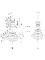
図1は、本発明の第1実施例に係るズームレンズの構成、及び各レンズ群の移動軌跡を示す図である。
本実施例に係るズームレンズは、物体側から順に、負の屈折力を有する第1レンズ群G1と、正の屈折力を有する第2レンズ群G2とからなる。
第1レンズ群G1は、物体側から順に、負の屈折力を有する前方負レンズ群Gfと後方負レンズ群Grとからなる。
前方負レンズ群Gfは、物体側から順に、物体側に凸面を向けた負メニスカスレンズLf1と、像側レンズ面が本発明の特徴的な非球面である物体側に凸面を向けた負メニスカスレンズLf2とからなる。
後方負レンズ群Grは、物体側から順に、像側レンズ面が非球面である樹脂材料とガラス材料の複合からなる物体側に凸面を向けた複合型負メニスカスレンズLr1と、両凹形状の負レンズLr2、両凸形状の正レンズLr3とからなる。
Hereinafter, zoom lenses according to embodiments of the present invention will be described with reference to the accompanying drawings.
(First embodiment)
FIG. 1 is a diagram illustrating the configuration of a zoom lens according to the first embodiment of the present invention and the movement locus of each lens group.
The zoom lens according to the present embodiment includes, in order from the object side, a first lens group G1 having a negative refractive power and a second lens group G2 having a positive refractive power.
The first lens group G1 includes, in order from the object side, a front negative lens group Gf having a negative refractive power and a rear negative lens group Gr.
The front negative lens group Gf includes, in order from the object side, a negative meniscus lens Lf1 having a convex surface directed toward the object side, and a negative meniscus lens having a convex surface directed toward the object side whose image side lens surface is the characteristic aspherical surface of the present invention. Lf2.
The rear negative lens group Gr includes, in order from the object side, a composite negative meniscus lens Lr1 having a convex surface facing the object side made of a composite of a resin material and a glass material having an aspheric image side lens surface, and a negative biconcave lens Lr1. The lens Lr2 and a biconvex positive lens Lr3.
第2レンズ群G2は、物体側から順に、物体側に凸面を向けた負メニスカスレンズL1と物体側に凸面を向けた正メニスカスレンズL2との接合よりなる接合正レンズと、開口絞りSと、物体側に凹面を向けた正メニスカスレンズL3と、両凹形状の負レンズL4と、両凸形状の正レンズL5と、物体側に凸面を向けた負メニスカスレンズL6と両凸形状の正レンズL7との接合よりなる接合正レンズと、物体側に凸面を向けた負メニスカスレンズL8と像側レンズ面が非球面である両凸形状の正レンズL9との接合よりなる非球面接合正レンズとからなる。 The second lens group G2, in order from the object side, a cemented positive lens formed by cementing a negative meniscus lens L1 having a convex surface toward the object side and a positive meniscus lens L2 having a convex surface toward the object side, an aperture stop S, A positive meniscus lens L3 having a concave surface facing the object side, a biconcave negative lens L4, a biconvex positive lens L5, a negative meniscus lens L6 having a convex surface facing the object side, and a biconvex positive lens L7 And a positive aspherical cemented lens formed by cementing a negative meniscus lens L8 having a convex surface toward the object side and a biconvex positive lens L9 having an aspheric image side lens surface. Become.
本実施形態において、広角端状態から望遠端状態への変倍は、第1レンズ群G1と第2レンズ群G2との間の空気間隔が縮小するように第1レンズ群G1、第2レンズ群G2を移動させることによって行う。
また、本実施形態において、第2レンズ群G2中の負メニスカスレンズL1と正メニスカスレンズL2との接合正レンズは、近距離合焦に際して第2レンズ群G2から分割して移動する合焦レンズ群であり、第2レンズ群G2を構成する他の各レンズは合焦に際して固定である。
なお、開口絞りSは、上述のように第2レンズ群G2中に備えられており、変倍に際して第2レンズ群G2を構成する各レンズと一体的に移動する。
In the present embodiment, zooming from the wide-angle end state to the telephoto end state is performed by the first lens group G1 and the second lens group so that the air gap between the first lens group G1 and the second lens group G2 is reduced. This is done by moving G2.
Further, in the present embodiment, the cemented positive lens of the negative meniscus lens L1 and the positive meniscus lens L2 in the second lens group G2 is divided from the second lens group G2 and moved when focusing at a short distance. The other lenses constituting the second lens group G2 are fixed at the time of focusing.
The aperture stop S is provided in the second lens group G2 as described above, and moves integrally with each lens constituting the second lens group G2 upon zooming.
以下の表1に、本発明の第1実施例に係るズームレンズの諸元の値を掲げる。
[全体諸元]において、fは焦点距離、2ωは画角(包括角)、FNOはFナンバーをそれぞれ示す。
[レンズデータ]において、面番号は物体側から数えたレンズ面の順番、riは物体側からi番目のレンズ面Riの曲率半径、diはレンズ面Riとレンズ面Ri+1との光軸上の面間隔、ni,νiはレンズ面Riとレンズ面Ri+1との間の媒質のd線(λ=587.56nm)に対する屈折率,アッベ数をそれぞれ示す。さらに、レンズデータ中の非球面には、星印(★)を付して曲率半径rの欄には近軸曲率半径を示し、κ及び各非球面係数は[非球面データ]の欄に記載する。
Table 1 below lists values of specifications of the zoom lens according to the first example of the present invention.
In [Overall specifications], f is a focal length, 2ω is an angle of view (inclusive angle), and FNO is an F number.
In [Lens data], the surface number is the order of the lens surfaces counted from the object side, ri is the radius of curvature of the i-th lens surface Ri from the object side, and di is on the optical axis between the lens surface Ri and the lens surface Ri + 1. , Ni and νi represent the refractive index and Abbe number for the d-line (λ = 587.56 nm) of the medium between the lens surface Ri and the lens surface Ri + 1, respectively. Further, the aspherical surface in the lens data is marked with an asterisk (*), the paraxial radius of curvature is indicated in the column of the radius of curvature r, and κ and each aspherical coefficient are described in the column of [Aspherical data]. To do.
[非球面データ]において、「E-n」は「×10−n」を示す。諸元表に示す非球面は、光軸から垂直方向の高さyにおける各非球面の頂点の接平面から光軸方向に沿った距離(サグ量)をX(y)、基準球面の曲率半径をr、円錐係数をκ、n次の非球面係数をCnとするとき、以下の非球面式で表される。なお、0(ゼロ)となる非球面係数はその記載を省略している。
X(y)=(y2/r)/〔1+(1−κ・y2/r2)1/2〕
+C4・y4+C6・y6+C8・y8+C10・y10+C12・y12
[可変間隔データ]において、βは物体と像間の結像倍率を示し、1-POSは広角端状態における無限遠合焦時、2-POSは中間焦点距離状態における無限遠合焦時、3-POSは望遠端状態における無限遠合焦時、4-POSは広角端状態における中間距離合焦時、5-POSは中間焦点距離状態における中間距離合焦時、6-POSは望遠端状態における中間距離合焦時、7-POSは広角端状態における近距離合焦時、8-POSは中間焦点距離状態における近距離合焦時、9-POSは望遠端状態における近距離合焦時をそれぞれ示している。
In [Aspherical data], “En” indicates “× 10 −n ”. The aspherical surface shown in the specification table is X (y) as the distance (sag amount) along the optical axis direction from the tangent plane of the apex of each aspherical surface at height y in the vertical direction from the optical axis, and the radius of curvature of the reference spherical surface Is represented by the following aspherical expression, where r is the conic coefficient, κ, and the nth-order aspherical coefficient is Cn. Note that the description of the aspherical coefficient that is 0 (zero) is omitted.
X (y) = (y 2 / r) / [1+ (1−κ · y 2 / r 2 ) 1/2 ]
+ C4 · y 4 + C6 · y 6 + C8 · y 8 + C10 · y 10 + C12 · y 12
In [Variable Interval Data], β indicates the imaging magnification between the object and the image, 1-POS is at infinity in the wide-angle end state, 2-POS is at infinity in the intermediate focal length state, 3 -POS is in focus at infinity in the telephoto end state, 4-POS is in focus at intermediate distance in the wide-angle end state, 5-POS is in focus at intermediate distance in the intermediate focal length state, and 6-POS is in telephoto end state When focusing at intermediate distance, 7-POS is for short distance focusing in the wide-angle end state, 8-POS is for short distance focusing in the intermediate focal length state, and 9-POS is for short distance focusing in the telephoto end state. Show.
ここで、以下の全ての諸元値において掲載されている焦点距離f、曲率半径r、その他長さの単位は一般に「mm」が使われる。しかし光学系は、比例拡大又は比例縮小しても同等の光学性能が得られるため、これに限られるものではない。
なお、以下の全ての実施例の諸元値においても、本実施例と同様の符号を用いる。
Here, the unit of the focal length f, the radius of curvature r, and other lengths listed in all the following specification values is generally “mm”. However, the optical system is not limited to this because an equivalent optical performance can be obtained even when proportional expansion or proportional reduction is performed.
In addition, also in the specification values of all the following examples, the same symbols as in this example are used.
(表1)
[全体諸元]
f = 14.4 〜 23.8mm
2ω = 114.7 〜 83.8゜
FNO= 2.88
[レンズデータ]
面番号 r d ν n
1) 60.3984 3.5000 46.58 1.804000
2) 32.2578 7.0500 1.0
3) 35.5108 4.0000 55.34 1.677900
4) 19.4795 12.9400 1.0 ★(最大有効径φ=49.74mm)
5) 89.6335 2.5000 52.64 1.740999
6) 26.4868 0.3000 38.09 1.553890
7) 30.4991 12.5000 1.0 ★
8) -70.2692 2.5600 82.52 1.497820
9) 47.2822 2.0000 1.0
10) 47.8177 5.9600 39.58 1.804398
11) -188.1989 d11 1.0
12) 34.3254 1.0000 42.71 1.834807
13) 19.3251 4.3300 47.04 1.623740
14) 537.9803 d14 1.0
15> 開口絞りS 1.6500 1.0
16) -265.6796 2.6500 64.10 1.516800
17) -47.8047 9.2200 1.0
18) -27.9975 1.6800 42.72 1.834810
19) 135.6792 0.1000 1.0
20) 35.5262 4.4700 50.80 1.570989
21) -69.9999 0.1000 1.0
22) 27.0980 1.3800 49.45 1.772789
23) 16.3144 8.5000 82.52 1.497820
24) -53.0000 1.7200 1.0
25) 1851.7083 1.0000 40.92 1.806098
26) 20.5737 6.3200 61.13 1.589130
27) -60.3799 BF 1.0 ★
[非球面データ(κ及び各非球面係数)]
面番号 κ C4 C6 C8 C10
4) 0.3800 -5.17970E-06 -5.02460E-09 -1.19110E-11 2.64530E-15
7) -0.3546 1.51670E-05 1.41920E-08 1.15200E-12 2.81920E-14
27) 5.9494 1.98780E-05 7.36870E-09 1.54420E-10 -6.11770E-13
[可変間隔データ]
<無限遠合焦時>
1-POS 2-POS 3-POS
f 14.39984 17.99926 23.79789
D0 ∞ ∞ ∞
d11 32.16889 16.60795 1.43931
d14 6.29963 6.29963 6.29963
BF 38.69454 44.53512 53.94475
<中間距離合焦時>
4-POS 5-POS 6-POS
β -0.02500 -0.02500 -0.02500
D0 536.7915 682.5129 916.1281
d11 33.42361 17.56746 2.18773
d14 5.04491 5.34012 5.55120
BF 38.69457 44.53517 53.94484
<近距離合焦時>
7-POS 8-POS 9-POS
β -0.08769 -0.10454 -0.13500
D0 125.0026 134.7240 140.4854
d11 36.60706 20.62151 5.45056
d14 1.86146 2.28607 2.28837
BF 38.69466 44.53536 53.94527
[条件式対応値]
条件式(1)= 2.25
条件式(2)= -4.86
条件式(3)= 0.381
(Table 1)
[Overall specifications]
f = 14.4 to 23.8mm
2ω = 114.7 to 83.8 ° FNO = 2.88
[Lens data]
Surface number r d v n
1) 60.3984 3.5000 46.58 1.804000
2) 32.2578 7.0500 1.0
3) 35.5108 4.0000 55.34 1.677900
4) 19.4795 12.9400 1.0 ★ (Maximum effective diameter φ = 49.74 mm)
5) 89.6335 2.5000 52.64 1.740999
6) 26.4868 0.3000 38.09 1.553890
7) 30.4991 12.5000 1.0 ★
8) -70.2692 2.5600 82.52 1.497820
9) 47.2822 2.0000 1.0
10) 47.8177 5.9600 39.58 1.804398
11) -188.1989 d11 1.0
12) 34.3254 1.0000 42.71 1.834807
13) 19.3251 4.3300 47.04 1.623740
14) 537.9803 d14 1.0
15> Aperture S 1.6500 1.0
16) -265.6796 2.6500 64.10 1.516800
17) -47.8047 9.2200 1.0
18) -27.9975 1.6800 42.72 1.834810
19) 135.6792 0.1000 1.0
20) 35.5262 4.4700 50.80 1.570989
21) -69.9999 0.1000 1.0
22) 27.0980 1.3800 49.45 1.772789
23) 16.3144 8.5000 82.52 1.497820
24) -53.0000 1.7200 1.0
25) 1851.7083 1.0000 40.92 1.806098
26) 20.5737 6.3200 61.13 1.589130
27) -60.3799 BF 1.0 ★
[Aspheric data (κ and each aspheric coefficient)]
Surface number κ C4 C6 C8 C10
4) 0.3800 -5.17970E-06 -5.02460E-09 -1.19110E-11 2.64530E-15
7) -0.3546 1.51670E-05 1.41920E-08 1.15200E-12 2.81920E-14
27) 5.9494 1.98780E-05 7.36870E-09 1.54420E-10 -6.11770E-13
[Variable interval data]
<At infinity focus>
1-POS 2-POS 3-POS
f 14.39984 17.99926 23.79789
D0 ∞ ∞ ∞
d11 32.16889 16.60795 1.43931
d14 6.29963 6.29963 6.29963
BF 38.69454 44.53512 53.94475
<When focusing at intermediate distance>
4-POS 5-POS 6-POS
β -0.02500 -0.02500 -0.02500
D0 536.7915 682.5129 916.1281
d11 33.42361 17.56746 2.18773
d14 5.04491 5.34012 5.55120
BF 38.69457 44.53517 53.94484
<At close focus>
7-POS 8-POS 9-POS
β -0.08769 -0.10454 -0.13500
D0 125.0026 134.7240 140.4854
d11 36.60706 20.62151 5.45056
d14 1.86146 2.28607 2.28837
BF 38.69466 44.53536 53.94527
[Conditional expression values]
Conditional expression (1) = 2.25
Conditional expression (2) = -4.86
Conditional expression (3) = 0.381
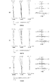
図2(a)、図2(b)、図2(c)はそれぞれ、本発明の第1実施例に係るズームレンズの広角端状態、中間焦点距離状態、望遠端状態における無限遠合焦時の諸収差図である。
各収差図において、FNOはFナンバー、Aは半画角(単位:度)、をそれぞれ示す。なお、球面収差図においては最大口径に対応するFナンバーの値を示し、非点収差図及び歪曲収差図においては半画角Aの最大値をそれぞれ示す。
2 (a), 2 (b), and 2 (c) are in-focus at infinity in the wide-angle end state, intermediate focal length state, and telephoto end state of the zoom lens according to Example 1 of the present invention, respectively. FIG.
In each aberration diagram, FNO represents an F number, and A represents a half angle of view (unit: degree). In the spherical aberration diagram, the F-number value corresponding to the maximum aperture is shown, and in the astigmatism diagram and the distortion diagram, the maximum value of the half field angle A is shown.
また、コマ収差図においては各半画角の値を示す。また、d,gはそれぞれ、d線(λ=587.56nm),g線(λ=435.84nm)の収差曲線を示す。さらに、非点収差図において、実線はサジタル像面、破線はメリジオナル像面をそれぞれ示す。
なお、以下に示す全実施例の諸収差図において、本実施例と同様の符号を用いる。
図2(a)、図2(b)、図2(c)より、本実施例に係るズームレンズは、広角端状態、中間焦点距離状態、望遠端状態の各状態において、諸収差を良好に補正していることがわかる。
In the coma aberration diagram, the values of the half angle of view are shown. D and g indicate aberration curves of the d-line (λ = 587.56 nm) and the g-line (λ = 435.84 nm), respectively. Further, in the astigmatism diagram, the solid line indicates the sagittal image plane, and the broken line indicates the meridional image plane.
In addition, in the various aberration diagrams of all the examples shown below, the same reference numerals as those in this example are used.
2 (a), 2 (b), and 2 (c), the zoom lens according to the present embodiment has excellent aberrations in each of the wide-angle end state, the intermediate focal length state, and the telephoto end state. You can see that it is corrected.
(第2実施例)
図3は、本発明の第2実施例に係るズームレンズの構成、及び各レンズ群の移動軌跡を示す図である。
本実施例に係るズームレンズは、物体側から順に、負の屈折力を有する第1レンズ群G1と、正の屈折力を有する第2レンズ群G2とからなる。
(Second embodiment)
FIG. 3 is a diagram showing the configuration of the zoom lens according to the second embodiment of the present invention and the movement locus of each lens group.
The zoom lens according to the present embodiment includes, in order from the object side, a first lens group G1 having a negative refractive power and a second lens group G2 having a positive refractive power.
第1レンズ群G1は、物体側から順に、負の屈折力を有する前方負レンズ群Gfと後方負レンズ群Grとからなる。
前方負レンズ群Gfは、物体側から順に、物体側に凸面を向けた負メニスカスレンズLf1と、像側レンズ面が本発明の特徴的な非球面である物体側に凸面を向けた負メニスカスレンズLf2とからなる。
後方負レンズ群Grは、物体側から順に、物体側に凸面を向けた正メニスカスレンズLr1と、像側レンズ面が非球面である樹脂材料とガラス材料の複合からなる両凹形状の複合型負レンズLr2と、両凹形状の負レンズLr3、両凸形状の正レンズLr4とからなる。
The first lens group G1 includes, in order from the object side, a front negative lens group Gf having a negative refractive power and a rear negative lens group Gr.
The front negative lens group Gf includes, in order from the object side, a negative meniscus lens Lf1 having a convex surface directed toward the object side, and a negative meniscus lens having a convex surface directed toward the object side whose image side lens surface is the characteristic aspherical surface of the present invention. Lf2.
The rear negative lens group Gr includes, in order from the object side, a positive meniscus lens Lr1 having a convex surface facing the object side, and a biconcave composite negative lens composed of a resin material and a glass material having an aspheric image side lens surface. It consists of a lens Lr2, a biconcave negative lens Lr3, and a biconvex positive lens Lr4.
第2レンズ群G2は、物体側から順に、物体側に凸面を向けた負メニスカスレンズL1と物体側に凸面を向けた正メニスカスレンズL2との接合よりなる接合正レンズと、開口絞りSと、物体側に凹面を向けた正メニスカスレンズL3と、両凹形状の負レンズL4と、両凸形状の正レンズL5と、物体側に凸面を向けた負メニスカスレンズL6と両凸形状の正レンズL7との接合よりなる接合正レンズと、物体側に凸面を向けた負メニスカスレンズL8と像側レンズ面が非球面である両凸形状の正レンズL9との接合よりなる非球面接合正レンズとからなる。 The second lens group G2, in order from the object side, a cemented positive lens formed by cementing a negative meniscus lens L1 having a convex surface toward the object side and a positive meniscus lens L2 having a convex surface toward the object side, an aperture stop S, A positive meniscus lens L3 having a concave surface facing the object side, a biconcave negative lens L4, a biconvex positive lens L5, a negative meniscus lens L6 having a convex surface facing the object side, and a biconvex positive lens L7 And a positive aspherical cemented lens formed by cementing a negative meniscus lens L8 having a convex surface toward the object side and a biconvex positive lens L9 having an aspheric image side lens surface. Become.
本実施形態において、広角端状態から望遠端状態への変倍は、第1レンズ群G1と第2レンズ群G2との間の空気間隔が縮小するように第1レンズ群G1、第2レンズ群G2を移動させることによって行う。
また、本実施形態において、第2レンズ群G2中の負メニスカスレンズL1と正メニスカスレンズL2との接合正レンズは、近距離合焦に際して第2レンズ群G2から分割して移動する合焦レンズ群であり、第2レンズ群G2を構成する他の各レンズは合焦に際して固定である。
なお、開口絞りSは、上述のように第2レンズ群G2中に備えられており、変倍に際して第2レンズ群G2を構成する各レンズと一体的に移動する。
以下の表2に、本発明の第2実施例に係るズームレンズの諸元の値を掲げる。
In the present embodiment, zooming from the wide-angle end state to the telephoto end state is performed by the first lens group G1 and the second lens group so that the air gap between the first lens group G1 and the second lens group G2 is reduced. This is done by moving G2.
Further, in the present embodiment, the cemented positive lens of the negative meniscus lens L1 and the positive meniscus lens L2 in the second lens group G2 is divided from the second lens group G2 and moved when focusing at a short distance. The other lenses constituting the second lens group G2 are fixed at the time of focusing.
The aperture stop S is provided in the second lens group G2 as described above, and moves integrally with each lens constituting the second lens group G2 upon zooming.
Table 2 below provides values of specifications of the zoom lens according to the second example of the present invention.
(表2)
[全体諸元]
f = 14.4 〜 23.8mm
2ω = 114.7 〜 83.8゜
FNO= 2.88
[レンズデータ]
面番号 r d ν n
1) 47.7912 3.5000 49.45 1.772789
2) 30.9498 10.0000 1.0
3) 41.1633 4.0000 61.09 1.589130
4) 19.7869 12.0000 1.0 ★(最大有効径φ=49.90mm)
5) 91.3576 4.0000 82.52 1.497820
6) 240.1699 0.8000 1.0
7) 1006.1910 2.0000 52.67 1.741000
8) 24.0000 0.3000 38.09 1.553890
9) 27.2373 12.0000 1.0 ★
10) -59.6826 2.0000 67.87 1.593189
11) 67.8295 1.0000 1.0
12) 52.0737 6.5000 39.58 1.804398
13) -88.0383 d13 1.0
14) 34.1179 1.0000 37.17 1.834000
15) 19.7303 6.2000 43.71 1.605620
16) 2031.7272 d16 1.0
17> 開口絞りS 1.5000 1.0
18) -28796.2450 4.0000 81.54 1.496999
19) -45.3898 7.4000 1.0
20) -28.7323 1.0000 33.89 1.803834
21) 71.8528 0.1000 1.0
22) 35.4462 4.9000 28.46 1.728250
23) -133.2653 0.1000 1.0
24) 25.3425 1.4000 37.16 1.834000
25) 16.1785 8.8000 82.52 1.497820
26) -54.5260 0.1000 1.0
27) 4388.4146 1.0000 42.71 1.834807
28) 19.5519 8.2000 61.13 1.589130
29) -50.8220 BF 1.0 ★
[非球面データ(κ及び各非球面係数)]
面番号 κ C4 C6 C8 C10 C12
4) 0.0306 2.02880E-07 8.26530E-10 -2.44250E-11 1.92290E-14 -0.28554E-17
9) -4.6395 4.51150E-05 -7.32380E-08 3.03190E-10 -6.65870E-13 0.70312E-15
29) 8.8248 2.21270E-05 1.65170E-08 1.55950E-10 -3.78420E-13 0.0
[可変間隔データ]
<無限遠合焦時>
1-POS 2-POS 3-POS
f 14.39975 17.99970 23.79962
D0 ∞ ∞ ∞
d13 30.85165 15.93246 1.38937
d16 5.95862 5.95862 5.95862
BF 38.81039 44.79147 54.42769
<中間距離合焦時>
4-POS 5-POS 6-POS
β -0.02500 -0.02500 -0.02500
D0 537.2377 682.8765 916.4440
d13 32.02463 16.83061 2.08890
d16 4.78564 5.06046 5.25909
BF 38.80791 44.78900 54.42521
<近距離合焦時>
7-POS 8-POS 9-POS
β -0.08793 -0.10523 -0.13647
D0 125.0014 133.9394 138.8462
d13 35.01025 19.71438 5.18094
d16 1.80002 2.17669 2.16705
BF 38.78038 44.74845 54.35532
[条件式対応値]
条件式(1)= 2.35
条件式(2)= -4.83
条件式(3)= 0.558
(Table 2)
[Overall specifications]
f = 14.4 to 23.8mm
2ω = 114.7 to 83.8 ° FNO = 2.88
[Lens data]
Surface number r d v n
1) 47.7912 3.5000 49.45 1.772789
2) 30.9498 10.0000 1.0
3) 41.1633 4.0000 61.09 1.589130
4) 19.7869 12.0000 1.0 ★ (Maximum effective diameter φ = 49.90mm)
5) 91.3576 4.0000 82.52 1.497820
6) 240.1699 0.8000 1.0
7) 1006.1910 2.0000 52.67 1.741000
8) 24.0000 0.3000 38.09 1.553890
9) 27.2373 12.0000 1.0 ★
10) -59.6826 2.0000 67.87 1.593189
11) 67.8295 1.0000 1.0
12) 52.0737 6.5000 39.58 1.804398
13) -88.0383 d13 1.0
14) 34.1179 1.0000 37.17 1.834000
15) 19.7303 6.2000 43.71 1.605620
16) 2031.7272 d16 1.0
17> Aperture stop S 1.5000 1.0
18) -28796.2450 4.0000 81.54 1.496999
19) -45.3898 7.4000 1.0
20) -28.7323 1.0000 33.89 1.803834
21) 71.8528 0.1000 1.0
22) 35.4462 4.9000 28.46 1.728250
23) -133.2653 0.1000 1.0
24) 25.3425 1.4000 37.16 1.834000
25) 16.1785 8.8000 82.52 1.497820
26) -54.5260 0.1000 1.0
27) 4388.4146 1.0000 42.71 1.834807
28) 19.5519 8.2000 61.13 1.589130
29) -50.8220 BF 1.0 ★
[Aspheric data (κ and each aspheric coefficient)]
Surface number κ C4 C6 C8 C10 C12
4) 0.0306 2.02880E-07 8.26530E-10 -2.44250E-11 1.92290E-14 -0.28554E-17
9) -4.6395 4.51150E-05 -7.32380E-08 3.03190E-10 -6.65870E-13 0.70312E-15
29) 8.8248 2.21270E-05 1.65170E-08 1.55950E-10 -3.78420E-13 0.0
[Variable interval data]
<At infinity focus>
1-POS 2-POS 3-POS
f 14.39975 17.99970 23.79962
D0 ∞ ∞ ∞
d13 30.85165 15.93246 1.38937
d16 5.95862 5.95862 5.95862
BF 38.81039 44.79147 54.42769
<When focusing at intermediate distance>
4-POS 5-POS 6-POS
β -0.02500 -0.02500 -0.02500
D0 537.2377 682.8765 916.4440
d13 32.02463 16.83061 2.08890
d16 4.78564 5.06046 5.25909
BF 38.80791 44.78900 54.42521
<At close focus>
7-POS 8-POS 9-POS
β -0.08793 -0.10523 -0.13647
D0 125.0014 133.9394 138.8462
d13 35.01025 19.71438 5.18094
d16 1.80002 2.17669 2.16705
BF 38.78038 44.74845 54.35532
[Conditional expression values]
Conditional expression (1) = 2.35
Conditional expression (2) = -4.83
Conditional expression (3) = 0.558
図4(a)、図4(b)、図4(c)はそれぞれ、本発明の第2実施例に係るズームレンズの広角端状態、中間焦点距離状態、望遠端状態における無限遠合焦時の諸収差図である。
図4(a)、図4(b)、図4(c)より、本実施例に係るズームレンズは、広角端状態、中間焦点距離状態、望遠端状態の各状態において、諸収差を良好に補正していることがわかる。
4 (a), 4 (b), and 4 (c) are in-focus at infinity in the wide-angle end state, intermediate focal length state, and telephoto end state of the zoom lens according to Example 2 of the present invention, respectively. FIG.
4 (a), 4 (b), and 4 (c), the zoom lens according to the present embodiment has excellent aberrations in each of the wide-angle end state, the intermediate focal length state, and the telephoto end state. You can see that it is corrected.
(第3実施例)
図5は、本発明の第3実施例に係るズームレンズの構成、及び各レンズ群の移動軌跡を示す図である。
本実施例に係るズームレンズは、物体側から順に、負の屈折力を有する第1レンズ群G1と、正の屈折力を有する第2レンズ群G2とからなる。
(Third embodiment)
FIG. 5 is a diagram showing the configuration of a zoom lens according to the third embodiment of the present invention and the movement locus of each lens group.
The zoom lens according to the present embodiment includes, in order from the object side, a first lens group G1 having a negative refractive power and a second lens group G2 having a positive refractive power.
第1レンズ群G1は、物体側から順に、負の屈折力を有する前方負レンズ群Gfと後方負レンズ群Grとからなる。
前方負レンズ群Gfは、物体側から順に、物体側に凸面を向けた負メニスカスレンズLf1と、物体側に凸面を向けた負メニスカスレンズLf2とからなる。そしてこの負メニスカスレンズLf2は、像側レンズ面が本発明の特徴的な非球面である樹脂材料と像側レンズ面が非球面であるガラス材料との複合からなる複合型負メニスカスレンズである。
後方負レンズ群Grは、物体側から順に、像側レンズ面が非球面である物体側に凸面を向けた負メニスカスレンズLr1と、両凹形状の負レンズLr2と物体側に凸面を向けた正メニスカスレンズLr3との接合よりなる接合負レンズと、両凸形状の正レンズLr4とからなる。
The first lens group G1 includes, in order from the object side, a front negative lens group Gf having a negative refractive power and a rear negative lens group Gr.
The front negative lens group Gf includes, in order from the object side, a negative meniscus lens Lf1 having a convex surface facing the object side and a negative meniscus lens Lf2 having a convex surface facing the object side. The negative meniscus lens Lf2 is a composite negative meniscus lens composed of a composite of a resin material whose image side lens surface is a characteristic aspherical surface of the present invention and a glass material whose image side lens surface is an aspheric surface.
The rear negative lens group Gr includes, in order from the object side, a negative meniscus lens Lr1 having a convex surface facing the object side whose image side lens surface is aspherical, a negative lens Lr2 having a biconcave shape, and a positive surface having a convex surface facing the object side. It consists of a cemented negative lens composed of a cemented meniscus lens Lr3 and a biconvex positive lens Lr4.
第2レンズ群G2は、物体側から順に、物体側に凸面を向けた負メニスカスレンズL1と両凸形状の正レンズL2との接合よりなる接合正レンズと、開口絞りSと、両凸形状の正レンズL3と、両凹形状の負レンズL4と、物体側に凸面を向けた正メニスカスレンズL5と、物体側に凸面を向けた負メニスカスレンズL6と物体側に凸面を向けた正メニスカスレンズL7との接合よりなる接合正レンズと、物体側に凸面を向けた負メニスカスレンズL8と像側レンズ面が非球面である両凸形状の正レンズL9との接合よりなる非球面接合正レンズとからなる。 The second lens group G2 includes, in order from the object side, a cemented positive lens formed by cementing a negative meniscus lens L1 having a convex surface toward the object side and a biconvex positive lens L2, an aperture stop S, and a biconvex shape. A positive lens L3, a biconcave negative lens L4, a positive meniscus lens L5 having a convex surface facing the object side, a negative meniscus lens L6 having a convex surface facing the object side, and a positive meniscus lens L7 having a convex surface facing the object side And a positive aspherical cemented lens formed by cementing a negative meniscus lens L8 having a convex surface toward the object side and a biconvex positive lens L9 having an aspheric image side lens surface. Become.
本実施形態において、広角端状態から望遠端状態への変倍は、第1レンズ群G1と第2レンズ群G2との間の空気間隔が縮小するように第1レンズ群G1、第2レンズ群G2を移動させることによって行う。
また、本実施形態において、第2レンズ群G2中の負メニスカスレンズL1と正メニスカスレンズL2との接合正レンズは、近距離合焦に際して第2レンズ群G2から分割して移動する合焦レンズ群であり、第2レンズ群G2を構成する他の各レンズは合焦に際して固定である。
なお、開口絞りSは、上述のように第2レンズ群G2中に備えられており、変倍に際して第2レンズ群G2を構成する各レンズと一体的に移動する。
以下の表3に、本発明の第3実施例に係るズームレンズの諸元の値を掲げる。
In the present embodiment, zooming from the wide-angle end state to the telephoto end state is performed by the first lens group G1 and the second lens group so that the air gap between the first lens group G1 and the second lens group G2 is reduced. This is done by moving G2.
Further, in the present embodiment, the cemented positive lens of the negative meniscus lens L1 and the positive meniscus lens L2 in the second lens group G2 is divided from the second lens group G2 and moved when focusing at a short distance. The other lenses constituting the second lens group G2 are fixed at the time of focusing.
The aperture stop S is provided in the second lens group G2 as described above, and moves integrally with each lens constituting the second lens group G2 upon zooming.
Table 3 below lists values of specifications of the zoom lens according to the third example of the present invention.
(表3)
[全体諸元]
f = 14.4 〜 23.8mm
2ω = 114.7 〜 83.8゜
FNO= 2.88
[レンズデータ]
面番号 r d ν n
1) 93.0730 3.5000 49.45 1.772789
2) 37.1507 5.5000 1.0
3) 36.4943 3.0000 55.34 1.677900
4) 15.9442 0.1000 56.41 1.501370 ★
5) 15.9442 11.0000 1.0 ★(最大有効径φ=48.10mm)
6) 40.6126 3.0000 49.45 1.772789
7) 28.1737 11.7000 1.0 ★
8) -147.5160 1.8000 65.42 1.603001
9) 26.0945 7.0000 33.75 1.648311
10) 63.5134 0.1625 1.0
11) 41.0779 6.0000 38.03 1.603420
12) -432.2463 d12 1.0
13) 33.7940 1.0000 37.35 1.834000
14) 19.0964 6.0000 56.36 1.568832
15) -308.5083 d15 1.0
16> 開口絞りS 1.5000 1.0
17) 71.2226 4.0000 54.55 1.514540
18) -73.5625 8.9693 1.0
19) -47.9538 1.3000 46.54 1.804109
20) 39.0026 0.1000 1.0
21) 22.2416 4.5000 40.11 1.762000
22) 122.2459 0.2000 1.0
23) 47.5013 1.3000 43.35 1.840421
24) 14.3353 7.0000 90.33 1.455999
25) 310.8760 0.2000 1.0
26) 59.6047 1.0000 23.01 1.860741
27) 34.0218 7.5000 61.13 1.589130
28) -32.6370 BF 1.0 ★
[非球面データ(κ及び各非球面係数)]
面番号 κ C4 C6 C8 C10 C12
4) -0.1124 1.38240E-07 3.40690E-09 -1.55360E-11 -1.91210E-14 0.31563E-16
5) -0.0881 1.43450E-07 2.03970E-10 -1.26120E-11 -1.54510E-14 0.31543E-16
7) 0.4109 1.51850E-05 -3.56670E-11 1.31390E-10 -3.03690E-13 0.55045E-15
28) 0.5209 5.24120E-06 -2.28310E-08 1.45290E-10 -8.71750E-13 0.0
[可変間隔データ]
<無限遠合焦時>
1-POS 2-POS 3-POS
f 14.40016 18.00031 23.80063
D0 ∞ ∞ ∞
d12 31.09655 16.06749 1.41732
d15 5.57959 5.57959 5.57959
BF 38.70186 44.89064 54.86160
<中間距離合焦時>
4-POS 5-POS 6-POS
β -0.02500 -0.02500 -0.02500
D0 539.6724 685.2757 918.8284
d12 32.23597 16.94179 2.10015
d15 4.44017 4.70529 4.89676
BF 38.70296 44.89174 54.86269
<近距離合焦時>
7-POS 8-POS 9-POS
β -0.08929 -0.10682 -0.13865
D0 124.9361 133.7762 138.4554
d12 35.19733 19.80369 5.17653
d15 1.47881 1.84339 1.82038
BF 38.71595 44.91080 54.89555
[条件式対応値]
条件式(1)= 2.36
条件式(2)= -3.08
条件式(3)= 0.092
(Table 3)
[Overall specifications]
f = 14.4 to 23.8mm
2ω = 114.7 to 83.8 ° FNO = 2.88
[Lens data]
Surface number r d v n
1) 93.0730 3.5000 49.45 1.772789
2) 37.1507 5.5000 1.0
3) 36.4943 3.0000 55.34 1.677900
4) 15.9442 0.1000 56.41 1.501370 ★
5) 15.9442 11.0000 1.0 ★ (Maximum effective diameter φ = 48.10mm)
6) 40.6126 3.0000 49.45 1.772789
7) 28.1737 11.7000 1.0 ★
8) -147.5160 1.8000 65.42 1.603001
9) 26.0945 7.0000 33.75 1.648311
10) 63.5134 0.1625 1.0
11) 41.0779 6.0000 38.03 1.603420
12) -432.2463 d12 1.0
13) 33.7940 1.0000 37.35 1.834000
14) 19.0964 6.0000 56.36 1.568832
15) -308.5083 d15 1.0
16> Aperture stop S 1.5000 1.0
17) 71.2226 4.0000 54.55 1.514540
18) -73.5625 8.9693 1.0
19) -47.9538 1.3000 46.54 1.804109
20) 39.0026 0.1000 1.0
21) 22.2416 4.5000 40.11 1.762000
22) 122.2459 0.2000 1.0
23) 47.5013 1.3000 43.35 1.840421
24) 14.3353 7.0000 90.33 1.455999
25) 310.8760 0.2000 1.0
26) 59.6047 1.0000 23.01 1.860741
27) 34.0218 7.5000 61.13 1.589130
28) -32.6370 BF 1.0 ★
[Aspheric data (κ and each aspheric coefficient)]
Surface number κ C4 C6 C8 C10 C12
4) -0.1124 1.38240E-07 3.40690E-09 -1.55360E-11 -1.91210E-14 0.31563E-16
5) -0.0881 1.43450E-07 2.03970E-10 -1.26120E-11 -1.54510E-14 0.31543E-16
7) 0.4109 1.51850E-05 -3.56670E-11 1.31390E-10 -3.03690E-13 0.55045E-15
28) 0.5209 5.24120E-06 -2.28310E-08 1.45290E-10 -8.71750E-13 0.0
[Variable interval data]
<At infinity focus>
1-POS 2-POS 3-POS
f 14.40016 18.00031 23.80063
D0 ∞ ∞ ∞
d12 31.09655 16.06749 1.41732
d15 5.57959 5.57959 5.57959
BF 38.70186 44.89064 54.86160
<When focusing at intermediate distance>
4-POS 5-POS 6-POS
β -0.02500 -0.02500 -0.02500
D0 539.6724 685.2757 918.8284
d12 32.23597 16.94179 2.10015
d15 4.44017 4.70529 4.89676
BF 38.70296 44.89174 54.86269
<At close focus>
7-POS 8-POS 9-POS
β -0.08929 -0.10682 -0.13865
D0 124.9361 133.7762 138.4554
d12 35.19733 19.80369 5.17653
d15 1.47881 1.84339 1.82038
BF 38.71595 44.91080 54.89555
[Conditional expression values]
Conditional expression (1) = 2.36
Conditional expression (2) = -3.08
Conditional expression (3) = 0.092
図6(a)、図6(b)、図6(c)はそれぞれ、本発明の第3実施例に係るズームレンズの広角端状態、中間焦点距離状態、望遠端状態における無限遠合焦時の諸収差図である。
図6(a)、図6(b)、図6(c)より、本実施例に係るズームレンズは、広角端状態、中間焦点距離状態、望遠端状態の各状態において、諸収差を良好に補正していることがわかる。
6 (a), 6 (b), and 6 (c) respectively show the zoom lens according to the third embodiment of the present invention when focused at infinity in the wide-angle end state, the intermediate focal length state, and the telephoto end state. FIG.
6 (a), 6 (b), and 6 (c), the zoom lens according to the present embodiment has excellent aberrations in each of the wide-angle end state, the intermediate focal length state, and the telephoto end state. You can see that it is corrected.
(第4実施例)
図7は、本発明の第4実施例に係るズームレンズの構成、及び各レンズ群の移動軌跡を示す図である。
本実施例に係るズームレンズは、物体側から順に、負の屈折力を有する第1レンズ群G1と、正の屈折力を有する第2レンズ群G2と、正の屈折力を有する第3レンズ群G3とからなる。
(Fourth embodiment)
FIG. 7 is a diagram showing the configuration of a zoom lens according to the fourth embodiment of the present invention and the movement locus of each lens group.
The zoom lens according to the present embodiment includes, in order from the object side, a first lens group G1 having a negative refractive power, a second lens group G2 having a positive refractive power, and a third lens group having a positive refractive power. G3.
第1レンズ群G1は、物体側から順に、負の屈折力を有する前方負レンズ群Gfと後方負レンズ群Grとからなる。
前方負レンズ群Gfは、物体側から順に、物体側に凸面を向けた負メニスカスレンズLf1と、像側レンズ面が本発明の特徴的な非球面である物体側に凸面を向けた負メニスカスレンズLf2とからなる。
後方負レンズ群Grは、物体側から順に、像側レンズ面が非球面である樹脂材料とガラス材料の複合からなる物体側に凸面を向けた複合型負メニスカスレンズLr1と、両凹形状の負レンズLr2と物体側に凸面を向けた正メニスカスレンズLr3との接合よりなる接合負レンズと、両凸形状の正レンズLr4とからなる。
The first lens group G1 includes, in order from the object side, a front negative lens group Gf having a negative refractive power and a rear negative lens group Gr.
The front negative lens group Gf includes, in order from the object side, a negative meniscus lens Lf1 having a convex surface directed toward the object side, and a negative meniscus lens having a convex surface directed toward the object side whose image side lens surface is the characteristic aspherical surface of the present invention. Lf2.
The rear negative lens group Gr includes, in order from the object side, a composite negative meniscus lens Lr1 having a convex surface facing the object side made of a composite of a resin material and a glass material having an aspheric image side lens surface, and a negative biconcave lens Lr1. It consists of a cemented negative lens composed of a lens Lr2 and a positive meniscus lens Lr3 having a convex surface facing the object side, and a biconvex positive lens Lr4.
第2レンズ群G2は、物体側から順に、物体側に凸面を向けた負メニスカスレンズL1と両凸形状の正レンズL2との接合よりなる接合正レンズと、開口絞りSと、両凸形状の正レンズL3と、物体側に凹面を向けた正メニスカスレンズL4と両凹形状の負レンズL5との接合よりなる接合負レンズとからなる。
第3レンズ群G3は、物体側に凸面を向けた正メニスカスレンズL6と、物体側に凸面を向けた負メニスカスレンズL7と両凸形状の正レンズL8との接合よりなる接合正レンズと、物体側に凸面を向けた負メニスカスレンズL9と像側レンズ面が非球面である両凸形状の正レンズL10との接合よりなる非球面接合正レンズとからなる。
The second lens group G2 includes, in order from the object side, a cemented positive lens formed by cementing a negative meniscus lens L1 having a convex surface toward the object side and a biconvex positive lens L2, an aperture stop S, and a biconvex shape. The lens includes a positive lens L3, and a cemented negative lens formed by cementing a positive meniscus lens L4 having a concave surface facing the object side and a biconcave negative lens L5.
The third lens group G3 includes a positive meniscus lens L6 having a convex surface directed toward the object side, a cemented positive lens formed by cementing a negative meniscus lens L7 having a convex surface directed toward the object side, and a biconvex positive lens L8, and an object And a negative meniscus lens L9 having a convex surface facing the side, and an aspheric cemented positive lens formed by cementing a biconvex positive lens L10 having an aspheric image side lens surface.
本実施形態において、広角端状態から望遠端状態への変倍は、第1レンズ群G1と第2レンズ群G2との間の空気間隔が縮小し、第2レンズ群G2と第3レンズ群G3との間の空気間隔が縮小するように、第1レンズ群G1、第2レンズ群G2、及び第3レンズ群G3を移動させることによって行う。
また、本実施形態において、第2レンズ群G2中の負メニスカスレンズL1と正メニスカスレンズL2との接合正レンズは、近距離合焦に際して第2レンズ群G2から分割して移動する合焦レンズ群であり、第2レンズ群G2を構成する他の各レンズは合焦に際して固定である。
なお、開口絞りSは、上述のように第2レンズ群G2中に備えられており、変倍に際して第2レンズ群G2を構成する各レンズと一体的に移動する。
以下の表4に、本発明の第4実施例に係るズームレンズの諸元の値を掲げる。
In this embodiment, zooming from the wide-angle end state to the telephoto end state reduces the air gap between the first lens group G1 and the second lens group G2, and the second lens group G2 and the third lens group G3. This is performed by moving the first lens group G1, the second lens group G2, and the third lens group G3 so that the air gap between the first lens group G1 and the second lens group G3 is reduced.
Further, in the present embodiment, the cemented positive lens of the negative meniscus lens L1 and the positive meniscus lens L2 in the second lens group G2 is divided from the second lens group G2 and moved when focusing at a short distance. The other lenses constituting the second lens group G2 are fixed at the time of focusing.
The aperture stop S is provided in the second lens group G2 as described above, and moves integrally with each lens constituting the second lens group G2 upon zooming.
Table 4 below provides values of specifications of the zoom lens according to Example 4 of the present invention.
(表4)
[全体諸元]
f = 14.4 〜 23.8mm
2ω = 114.7 〜 83.8゜
FNO= 2.88
[レンズデータ]
面番号 r d ν n
1) 56.1483 3.5000 49.45 1.772789
2) 31.2488 6.7024 1.0
3) 36.1882 2.5000 55.34 1.677900
4) 17.1957 14.0890 1.0 ★(最大有効径φ=46.16)
5) 191.6042 2.0000 52.64 1.740999
6) 35.1321 10.3136 1.0 ★
7) -93.1738 1.0000 65.42 1.603001
8) 38.6142 6.1647 33.75 1.648311
9) 216.2089 0.2000 1.0
10) 51.3687 6.6064 44.41 1.612658
11) -164.0143 d11 1.0
12) 37.1736 1.0000 37.20 1.834000
13) 21.4900 6.2536 56.36 1.568832
14) -327.7174 d14 1.0
15> 0.0000 1.5000 1.0
16) 48.5898 5.0635 52.43 1.517417
17) -61.5418 1.0307 1.000000
18) 0.0000 3.3669 1.0
19) -44.2032 3.5914 33.75 1.648311
20) -25.1943 1.0000 49.45 1.772789
21) 39.4935 d21 1.0
22) 22.0848 5.0413 40.10 1.762001
23) 142.5353 0.2000 1.0
24) 49.2619 1.0000 44.69 1.802180
25) 13.7312 6.5966 90.33 1.455999
26) -7195.404 0.8235 1.0
27) 108.0634 1.0000 23.01 1.860741
28) 33.1536 6.6849 61.13 1.589130
29) -32.7920 BF 1.0 ★
[非球面データ(κ及び各非球面係数)]
面番号 κ C4 C6 C8 C10 C12
4) -0.0015 2.96460E-06 3.31750E-10 -8.46290E-12 -3.96050E-14 0.33986E-16
6) 0.4308 1.18490E-05 -8.34650E-09 1.43840E-10 -4.01800E-13 0.52321E-15
29) 0.4753 6.10030E-06 -3.11380E-08 2.64060E-10 -1.54430E-12 0.0
[可変間隔データ]
<無限遠合焦時>
1-POS 2-POS 3-POS
f 14.39970 17.99958 23.79936
D0 ∞ ∞ ∞
d11 32.05059 15.92226 1.00000
d14 6.23155 6.23155 6.23155
d21 0.78923 0.69368 0.20000
BF 38.69917 44.49425 53.77415
<中間距離合焦時>
4-POS 5-POS 6-POS
β -0.02500 -0.02500 -0.02500
D0 538.88560 684.63850 918.19630
d11 33.38100 16.93461 1.78251
d14 4.90114 5.21920 5.44904
d21 0.78923 0.69368 0.20000
Bf 38.69917 44.49425 53.77415
<近距離合焦時>
7-POS 8-POS 9-POS
f -0.08882 -0.10540 -0.13572
D0 125.00100 135.42970 141.56570
d11 36.82144 20.19416 5.22098
d14 1.46070 1.95965 2.01057
d21 0.78923 0.69368 0.20000
BF 38.69917 44.49425 53.77415
[条件式対応値]
条件式(1)= 0.0295
条件式(2)= -3.54
条件式(3)= 0.221
(Table 4)
[Overall specifications]
f = 14.4 to 23.8mm
2ω = 114.7 to 83.8 ° FNO = 2.88
[Lens data]
Surface number r d v n
1) 56.1483 3.5000 49.45 1.772789
2) 31.2488 6.7024 1.0
3) 36.1882 2.5000 55.34 1.677900
4) 17.1957 14.0890 1.0 ★ (Maximum effective diameter φ = 46.16)
5) 191.6042 2.0000 52.64 1.740999
6) 35.1321 10.3136 1.0 ★
7) -93.1738 1.0000 65.42 1.603001
8) 38.6142 6.1647 33.75 1.648311
9) 216.2089 0.2000 1.0
10) 51.3687 6.6064 44.41 1.612658
11) -164.0143 d11 1.0
12) 37.1736 1.0000 37.20 1.834000
13) 21.4900 6.2536 56.36 1.568832
14) -327.7174 d14 1.0
15> 0.0000 1.5000 1.0
16) 48.5898 5.0635 52.43 1.517417
17) -61.5418 1.0307 1.000000
18) 0.0000 3.3669 1.0
19) -44.2032 3.5914 33.75 1.648311
20) -25.1943 1.0000 49.45 1.772789
21) 39.4935 d21 1.0
22) 22.0848 5.0413 40.10 1.762001
23) 142.5353 0.2000 1.0
24) 49.2619 1.0000 44.69 1.802180
25) 13.7312 6.5966 90.33 1.455999
26) -7195.404 0.8235 1.0
27) 108.0634 1.0000 23.01 1.860741
28) 33.1536 6.6849 61.13 1.589130
29) -32.7920 BF 1.0 ★
[Aspheric data (κ and each aspheric coefficient)]
Surface number κ C4 C6 C8 C10 C12
4) -0.0015 2.96460E-06 3.31750E-10 -8.46290E-12 -3.96050E-14 0.33986E-16
6) 0.4308 1.18490E-05 -8.34650E-09 1.43840E-10 -4.01800E-13 0.52321E-15
29) 0.4753 6.10030E-06 -3.11380E-08 2.64060E-10 -1.54430E-12 0.0
[Variable interval data]
<At infinity focus>
1-POS 2-POS 3-POS
f 14.39970 17.99958 23.79936
D0 ∞ ∞ ∞
d11 32.05059 15.92226 1.00000
d14 6.23155 6.23155 6.23155
d21 0.78923 0.69368 0.20000
BF 38.69917 44.49425 53.77415
<When focusing at intermediate distance>
4-POS 5-POS 6-POS
β -0.02500 -0.02500 -0.02500
D0 538.88560 684.63850 918.19630
d11 33.38100 16.93461 1.78251
d14 4.90114 5.21920 5.44904
d21 0.78923 0.69368 0.20000
Bf 38.69917 44.49425 53.77415
<At close focus>
7-POS 8-POS 9-POS
f -0.08882 -0.10540 -0.13572
D0 125.00100 135.42970 141.56570
d11 36.82144 20.19416 5.22098
d14 1.46070 1.95965 2.01057
d21 0.78923 0.69368 0.20000
BF 38.69917 44.49425 53.77415
[Conditional expression values]
Conditional expression (1) = 0.0295
Conditional expression (2) = -3.54
Conditional expression (3) = 0.221
図8(a)、図8(b)、図8(c)はそれぞれ、本発明の第4実施例に係るズームレンズの広角端状態、中間焦点距離状態、望遠端状態における無限遠合焦時の諸収差図である。
図8(a)、図8(b)、図8(c)より、本実施例に係るズームレンズは、広角端状態、中間焦点距離状態、望遠端状態の各状態において、諸収差を良好に補正していることがわかる。
8 (a), 8 (b), and 8 (c) are in-focus at infinity in the wide-angle end state, the intermediate focal length state, and the telephoto end state of the zoom lens according to Example 4 of the present invention, respectively. FIG.
8 (a), 8 (b), and 8 (c), the zoom lens according to the present example has excellent aberrations in each of the wide-angle end state, the intermediate focal length state, and the telephoto end state. You can see that it is corrected.
上記各実施例によれば、2ω=114.7〜83.8°という通常の射影方式では限界に近いほどの大画角を有する超広角領域までカバーし、約1.65倍の変倍比を有し、さらに各焦点距離状態においてFナンバーがF2.88という今までにない明るさを有し、構成が単純で製造が容易であり、小型でダウンサイジングされた超広角大口径ズームレンズを実現することができる。 According to each of the above embodiments, the normal projection method of 2ω = 14.7 to 83.8 ° covers a super wide angle region having a large angle of view that is close to the limit, and a zoom ratio of about 1.65 times. And an ultra-wide-angle large-aperture zoom lens that has an unprecedented brightness with an F-number of F2.88 in each focal length state, is simple in structure, easy to manufacture, and is downsized. Can be realized.
なお、本発明の実施例として、2群構成及び3群構成のレンズ系を示したが、該2群又は3群に付加レンズ群を加えただけのレンズ系も本発明の効果を内在した同等のレンズ系であることは言うまでもない。また、各レンズ群内の構成においても、実施例の構成に付加レンズを加えただけのレンズ群も本発明の効果を内在した同等のレンズ群であることは言うまでもない。
なお、上記各実施例は本発明の一具体例を示しているものであり、本発明はこれらに限定されるものではない。
なお、上記第1、2、4実施例は本発明の実施例であり、上記第3実施例は本発明の参考例である。
In addition, as an embodiment of the present invention, a lens system having a two-group structure and a three-group structure is shown, but a lens system in which an additional lens group is added to the second group or the third group is equivalent to the effect of the present invention. It goes without saying that this is a lens system. In addition, in the configuration within each lens group, it goes without saying that a lens group in which an additional lens is added to the configuration of the embodiment is an equivalent lens group in which the effects of the present invention are inherent.
In addition, each said Example has shown one specific example of this invention, and this invention is not limited to these.
The first, second and fourth examples are examples of the present invention, and the third example is a reference example of the present invention.
G1 第1レンズ群
G2 第2レンズ群
Gf 前方負レンズ群
Gr 後方負レンズ群
S 開口絞り
G1 First lens group G2 Second lens group Gf Front negative lens group Gr Back negative lens group S Aperture stop
Claims (10)
前記第1レンズ群は、物体側から順に、負の屈折力を有する前方負レンズ群と後方負レンズ群とにより、実質的に2個のレンズ群からなり、
前記前方負レンズ群は、実質的に2つの負レンズからなり、当該2つの負レンズのうちの像側の負レンズは少なくとも1面の非球面を有する非球面レンズであり、
前記後方負レンズ群は、負レンズと正レンズとを少なくとも含む複数のレンズを有し、
前記前方負レンズ群中の前記非球面レンズは、以下の条件式を満足することを特徴とするズームレンズ。
0<{(dφmax−d0)/hmax}/{(d30−d0)/h30}<3
−15<fasp/fw<−1.7
0.221≦ff/fr≦0.63
但し、
d0 :前記非球面レンズの光軸上の厚さ(中心厚)
dφmax:前記非球面レンズの像側レンズ面の最大有効径の位置における光軸と平行な厚さ
d30 :前記非球面レンズの像側レンズ面の最大有効径の3割位置における光軸と平行な厚さ
hmax :前記非球面レンズの像側レンズ面の最大有効半径
h30 :前記非球面レンズの像側レンズ面の最大有効径の3割位置における有効半径
fasp :前記非球面レンズの近軸焦点距離
fw :広角端状態における無限遠合焦時の前記ズームレンズ全系の焦点距離
ff :前記第1レンズ群における前記前方負レンズ群の焦点距離
fr :前記第1レンズ群における前記後方負レンズ群の焦点距離 In order from the object side, a first lens group having a negative refractive power and a second lens group having a positive refractive power are provided, and an air gap between the first lens group and the second lens group is changed. In zoom lenses that change magnification by
The first lens group includes, in order from the object side, a front negative lens group having a negative refractive power and a rear negative lens group, and substantially consists of two lens groups .
The front negative lens group is substantially two negative lens or Rannahli, the image side of the negative lens of the two negative lens is an aspheric lens having at least one aspherical surface,
The rear negative lens group has a plurality of lenses including at least a negative lens and a positive lens,
The zoom lens according to claim 1, wherein the aspheric lens in the front negative lens group satisfies the following conditional expression.
0 <{(dφmax−d0) / hmax} / {(d30−d0) / h30} <3
−15 <fasp / fw <−1.7
0.221 ≦ ff / fr ≦ 0.63
However,
d0: thickness of the aspheric lens on the optical axis (center thickness)
dφmax: thickness parallel to the optical axis at the position of the maximum effective diameter of the image side lens surface of the aspheric lens d30: parallel to the optical axis at the position of 30% of the maximum effective diameter of the image side lens surface of the aspheric lens Thickness hmax: Maximum effective radius of image side lens surface of the aspheric lens h30: Effective radius fasp at 30% position of maximum effective diameter of the image side lens surface of the aspheric lens: Paraxial focal length of the aspheric lens fw: focal length of the entire zoom lens system at the time of focusing at infinity in the wide-angle end state ff: focal length of the front negative lens group in the first lens group fr: focal length of the rear negative lens group in the first lens group Focal length
前記接合正レンズは、近距離合焦に際して、前記第2レンズ群から分割して移動する合焦レンズ群であることを特徴とする請求項2に記載のズームレンズ。 The second lens group has a cemented positive lens of a negative meniscus lens and a positive meniscus lens,
The zoom lens according to claim 2, wherein the cemented positive lens is a focusing lens group that moves while being divided from the second lens group when focusing at a short distance.
前記第1レンズ群と前記第2レンズ群との空気間隔及び前記第2レンズ群と前記第3レンズ群との空気間隔を変化させることによって変倍することを特徴とする請求項1から請求項9のいずれか1項に記載のズームレンズ。 The zoom lens has a third lens group having a positive refractive power on the image side of the second lens group,
The zooming is performed by changing an air gap between the first lens group and the second lens group and an air gap between the second lens group and the third lens group. 10. The zoom lens according to any one of 9 above.
Priority Applications (1)
| Application Number | Priority Date | Filing Date | Title |
|---|---|---|---|
| JP2005285396A JP4945989B2 (en) | 2005-09-29 | 2005-09-29 | Zoom lens |
Applications Claiming Priority (1)
| Application Number | Priority Date | Filing Date | Title |
|---|---|---|---|
| JP2005285396A JP4945989B2 (en) | 2005-09-29 | 2005-09-29 | Zoom lens |
Publications (3)
| Publication Number | Publication Date |
|---|---|
| JP2007094174A JP2007094174A (en) | 2007-04-12 |
| JP2007094174A5 JP2007094174A5 (en) | 2008-12-04 |
| JP4945989B2 true JP4945989B2 (en) | 2012-06-06 |
Family
ID=37979947
Family Applications (1)
| Application Number | Title | Priority Date | Filing Date |
|---|---|---|---|
| JP2005285396A Expired - Fee Related JP4945989B2 (en) | 2005-09-29 | 2005-09-29 | Zoom lens |
Country Status (1)
| Country | Link |
|---|---|
| JP (1) | JP4945989B2 (en) |
Families Citing this family (28)
| Publication number | Priority date | Publication date | Assignee | Title |
|---|---|---|---|---|
| JP4978836B2 (en) * | 2007-03-19 | 2012-07-18 | 株式会社ニコン | Zoom lens, optical apparatus, and imaging method |
| JP5207761B2 (en) | 2008-02-12 | 2013-06-12 | キヤノン株式会社 | Optical system and optical apparatus having the same |
| JP4672755B2 (en) | 2008-06-30 | 2011-04-20 | 富士フイルム株式会社 | Magnification optical system and imaging device |
| JP5360472B2 (en) * | 2009-02-04 | 2013-12-04 | 株式会社ニコン | Zoom lens and optical apparatus provided with the zoom lens |
| JP4692857B2 (en) | 2009-02-04 | 2011-06-01 | ソニー株式会社 | Variable focal length lens system and imaging apparatus |
| JP4678555B2 (en) * | 2009-02-27 | 2011-04-27 | ソニー株式会社 | Variable focal length lens system and imaging apparatus |
| JP2010271643A (en) | 2009-05-25 | 2010-12-02 | Sony Corp | Variable focal length lens system and image pick up apparatus |
| JP5445040B2 (en) * | 2009-11-10 | 2014-03-19 | 株式会社ニコン | Wide angle lens, imaging device, and manufacturing method of wide angle lens |
| US8699143B2 (en) | 2009-11-10 | 2014-04-15 | Nikon Corporation | Wide-angle lens, imaging apparatus, and method for manufacturing wide-angle lens |
| JP5434496B2 (en) * | 2009-11-10 | 2014-03-05 | 株式会社ニコン | Wide angle lens, imaging device, and manufacturing method of wide angle lens |
| JP5428775B2 (en) * | 2009-11-10 | 2014-02-26 | 株式会社ニコン | Wide angle lens, imaging device, and manufacturing method of wide angle lens |
| JP2011175161A (en) * | 2010-02-25 | 2011-09-08 | Tamron Co Ltd | Zoom lens |
| US8830592B2 (en) | 2010-06-23 | 2014-09-09 | Nikon Corporation | Zoom lens, imaging apparatus, and method for manufacturing zoom lens |
| JP5510114B2 (en) * | 2010-06-23 | 2014-06-04 | 株式会社ニコン | Zoom lens, imaging device, and zoom lens manufacturing method |
| JP2013044964A (en) | 2011-08-24 | 2013-03-04 | Tamron Co Ltd | Zoom lens |
| JP5930895B2 (en) * | 2012-07-18 | 2016-06-08 | キヤノン株式会社 | Zoom lens and imaging apparatus having the same |
| TWI507727B (en) * | 2013-04-30 | 2015-11-11 | Young Optics Inc | Zoom lens |
| JP6046565B2 (en) * | 2013-07-19 | 2016-12-14 | 富士フイルム株式会社 | Imaging lens and imaging apparatus |
| JP6226610B2 (en) * | 2013-07-30 | 2017-11-08 | キヤノン株式会社 | Zoom lens and imaging apparatus having the same |
| JP6226611B2 (en) * | 2013-07-30 | 2017-11-08 | キヤノン株式会社 | Zoom lens and imaging apparatus having the same |
| JP6452285B2 (en) | 2013-11-22 | 2019-01-16 | キヤノン株式会社 | Zoom lens and imaging apparatus having the same |
| WO2015178095A1 (en) | 2014-05-19 | 2015-11-26 | オリンパス株式会社 | Zoom lens and image-capturing device having same |
| JP6518039B2 (en) * | 2014-05-19 | 2019-05-22 | オリンパス株式会社 | Zoom lens and imaging device having the same |
| JP6562612B2 (en) | 2014-10-03 | 2019-08-21 | キヤノン株式会社 | Zoom lens and imaging apparatus having the same |
| JP2019159187A (en) * | 2018-03-15 | 2019-09-19 | 株式会社ニコン | Optical system, optical device, and method of manufacturing optical system |
| WO2019187195A1 (en) | 2018-03-27 | 2019-10-03 | オリンパス株式会社 | Objective optical system for endoscope |
| WO2019207699A1 (en) * | 2018-04-26 | 2019-10-31 | オリンパス株式会社 | Objective optical system and imaging device using same |
| JP6876850B2 (en) * | 2020-04-23 | 2021-05-26 | 株式会社タムロン | Zoom lens and imaging device |
Family Cites Families (5)
| Publication number | Priority date | Publication date | Assignee | Title |
|---|---|---|---|---|
| JP4505910B2 (en) * | 1999-12-08 | 2010-07-21 | 株式会社ニコン | Zoom lens and photographing apparatus provided with the lens |
| JP2004093593A (en) * | 2002-08-29 | 2004-03-25 | Konica Minolta Holdings Inc | Zoom lens |
| JP4380206B2 (en) * | 2003-04-14 | 2009-12-09 | カシオ計算機株式会社 | Projection lens |
| JP4642408B2 (en) * | 2003-08-20 | 2011-03-02 | オリンパス株式会社 | Zoom lens and camera using the same |
| JP4632724B2 (en) * | 2004-09-07 | 2011-02-16 | オリンパス株式会社 | Zoom lens |
-
2005
- 2005-09-29 JP JP2005285396A patent/JP4945989B2/en not_active Expired - Fee Related
Also Published As
| Publication number | Publication date |
|---|---|
| JP2007094174A (en) | 2007-04-12 |
Similar Documents
| Publication | Publication Date | Title |
|---|---|---|
| JP4945989B2 (en) | Zoom lens | |
| JP4259047B2 (en) | Super wide-angle zoom lens | |
| US7227700B2 (en) | Wide zoom lens system | |
| US7239456B2 (en) | Super wide-angle lens system and image-capturing device using the same | |
| US7532411B2 (en) | High zoom ratio zoom lens system | |
| JP5028776B2 (en) | Zoom lens | |
| US8867147B2 (en) | Imaging lens, optical apparatus equipped therewith and method for manufacturing imaging lens | |
| JP4967294B2 (en) | 2 group zoom lens | |
| JP4862263B2 (en) | Super wide-angle lens and photographing apparatus equipped with the super-wide angle lens | |
| JP5017899B2 (en) | Zoom lens, imaging device, zooming method | |
| JP2004021223A6 (en) | Super wide-angle zoom lens | |
| JP3200925B2 (en) | Zoom lens with wide angle of view | |
| JPH04235514A (en) | Super-wide angle zoom lens | |
| JPH05249373A (en) | Wide-angle zoom lens | |
| JP5428775B2 (en) | Wide angle lens, imaging device, and manufacturing method of wide angle lens | |
| JPH04235515A (en) | Super-wide angle zoom lens | |
| JP4654506B2 (en) | Zoom lens | |
| JP4325200B2 (en) | Zoom lens | |
| JP4929902B2 (en) | Single focus lens and imaging apparatus having the same | |
| JPH0894933A (en) | High magnifying power zoom lens | |
| JP4505910B2 (en) | Zoom lens and photographing apparatus provided with the lens | |
| JP4839763B2 (en) | Wide angle lens | |
| JP3551520B2 (en) | Zoom lens | |
| JP6758640B2 (en) | Zoom lens | |
| JP4210876B2 (en) | Zoom lens |
Legal Events
| Date | Code | Title | Description |
|---|---|---|---|
| A621 | Written request for application examination |
Free format text: JAPANESE INTERMEDIATE CODE: A621 Effective date: 20080825 |
|
| A521 | Written amendment |
Free format text: JAPANESE INTERMEDIATE CODE: A523 Effective date: 20081022 |
|
| A977 | Report on retrieval |
Free format text: JAPANESE INTERMEDIATE CODE: A971007 Effective date: 20110527 |
|
| A131 | Notification of reasons for refusal |
Free format text: JAPANESE INTERMEDIATE CODE: A131 Effective date: 20110621 |
|
| A521 | Written amendment |
Free format text: JAPANESE INTERMEDIATE CODE: A523 Effective date: 20110817 |
|
| A131 | Notification of reasons for refusal |
Free format text: JAPANESE INTERMEDIATE CODE: A131 Effective date: 20111115 |
|
| A521 | Written amendment |
Free format text: JAPANESE INTERMEDIATE CODE: A523 Effective date: 20120116 |
|
| TRDD | Decision of grant or rejection written | ||
| A01 | Written decision to grant a patent or to grant a registration (utility model) |
Free format text: JAPANESE INTERMEDIATE CODE: A01 Effective date: 20120207 |
|
| A01 | Written decision to grant a patent or to grant a registration (utility model) |
Free format text: JAPANESE INTERMEDIATE CODE: A01 |
|
| A61 | First payment of annual fees (during grant procedure) |
Free format text: JAPANESE INTERMEDIATE CODE: A61 Effective date: 20120220 |
|
| FPAY | Renewal fee payment (event date is renewal date of database) |
Free format text: PAYMENT UNTIL: 20150316 Year of fee payment: 3 |
|
| R150 | Certificate of patent or registration of utility model |
Ref document number: 4945989 Country of ref document: JP Free format text: JAPANESE INTERMEDIATE CODE: R150 Free format text: JAPANESE INTERMEDIATE CODE: R150 |
|
| FPAY | Renewal fee payment (event date is renewal date of database) |
Free format text: PAYMENT UNTIL: 20150316 Year of fee payment: 3 |
|
| R250 | Receipt of annual fees |
Free format text: JAPANESE INTERMEDIATE CODE: R250 |
|
| R250 | Receipt of annual fees |
Free format text: JAPANESE INTERMEDIATE CODE: R250 |
|
| R250 | Receipt of annual fees |
Free format text: JAPANESE INTERMEDIATE CODE: R250 |
|
| R250 | Receipt of annual fees |
Free format text: JAPANESE INTERMEDIATE CODE: R250 |
|
| R250 | Receipt of annual fees |
Free format text: JAPANESE INTERMEDIATE CODE: R250 |
|
| LAPS | Cancellation because of no payment of annual fees |