JP4941252B2 - Case-hardened steel for power transmission parts - Google Patents
Case-hardened steel for power transmission parts Download PDFInfo
- Publication number
- JP4941252B2 JP4941252B2 JP2007304221A JP2007304221A JP4941252B2 JP 4941252 B2 JP4941252 B2 JP 4941252B2 JP 2007304221 A JP2007304221 A JP 2007304221A JP 2007304221 A JP2007304221 A JP 2007304221A JP 4941252 B2 JP4941252 B2 JP 4941252B2
- Authority
- JP
- Japan
- Prior art keywords
- steel
- content
- less
- value
- hardness
- Prior art date
- Legal status (The legal status is an assumption and is not a legal conclusion. Google has not performed a legal analysis and makes no representation as to the accuracy of the status listed.)
- Active
Links
Images


Description
本発明は、動力伝達部品用肌焼鋼、詳しくは、面圧疲労強度に優れた動力伝達部品用肌焼鋼に関する。より詳しくは、ピッチング強度、スポーリング強度および低サイクル曲げ疲労強度に優れた動力伝達部品用肌焼鋼に関する。 The present invention relates to a case hardening steel for power transmission parts, and more particularly, to a case hardening steel for power transmission parts having excellent surface fatigue strength. More specifically, the present invention relates to a case hardening steel for power transmission parts having excellent pitching strength, spalling strength and low cycle bending fatigue strength.
自動車の歯車、シャフトおよび等速ジョイントなどの動力伝達部品は、従来、JIS G 4053(2003)に規定されている機械構造用合金鋼鋼材を鍛造や切削などの加工により所定の形状に成形して、浸炭焼入れや浸炭窒化焼入れを施し、その後さらに焼戻しを行って製造されている。 Conventionally, power transmission parts such as automobile gears, shafts, and constant velocity joints are formed by machining alloy steel materials for machine structures specified in JIS G 4053 (2003) into a predetermined shape by processing such as forging or cutting. It is manufactured by subjecting it to carburizing and quenching and carbonitriding and quenching.
従来は上記の部品については、一般に、面圧疲労の一種であるピッチングに対する強度を向上させることが重視されてきた。 Conventionally, in the above parts, it has been emphasized to improve the strength against pitching, which is a kind of surface pressure fatigue.
しかしながら、部品使用時の接触面の温度は300℃程度にまで上昇するといわれていることから、最近では使用時における表層での焼戻し軟化を抑制したいとの要望があり、さらにまた、自動車のエンジントルク増大により、動力伝達部品にかかる応力も大きくなってきたため、ピッチング強度に加えて、従来よりも優れたスポーリング強度と低サイクル曲げ疲労強度を具備させたいとの要望も極めて大きくなっている。 However, since it is said that the temperature of the contact surface at the time of use of the component rises to about 300 ° C., recently there has been a demand for suppressing temper softening on the surface layer at the time of use. Due to the increase, the stress applied to the power transmission component has also increased, so that in addition to the pitching strength, there has been a great demand for providing a spalling strength and a low cycle bending fatigue strength superior to those of the prior art.
そこで、前記した要望に応えるべく、例えば、特許文献1〜3に、上記部品の素材用としてSiを添加した鋼が提案されている。
Therefore, in order to meet the above-described demand, for example,
具体的には、特許文献1に、質量%で、0.5〜2.0%のSiなど特定の化学組成を有し、〔Q=34140−605Si(%)+183Mn(%)+136Cr(%)+122Mo(%)〕の式で定義される鋼中の炭素拡散の活性化エネルギQの値が34000(kca1)以下の、SCr420鋼よりも浸炭時間が短縮可能な「肌焼鋼」に関する技術が開示されている。
Specifically,
特許文献2には、質量%で、0.35〜1.3%のSiなど特定の化学組成を有し、浸炭層のオーステナイト結晶粒度が7番以上、表面の炭素含有量が0.9〜1.5%であり、表面の残留オーステナイト量が25〜40%である「転動疲労特性に優れた浸炭材」に関する技術が開示されている。
特許文献3には、質量%で、0.01〜2.3%のSiなど特定の化学組成を有し、熱間圧延後のNb(CN)の析出量が0.005%以上であり、AlNの析出量を0.015%以下に制限し、ベイナイトの組織分率が30%以下であり、熱間圧延方向に平行な断面の組織のフェライトバンドの評点が1〜5であり、硬さHVが成分パラメータで規定された範囲にある「高温浸炭用鋼」に関する技術が開示されている。 Patent Document 3 has a specific chemical composition such as Si of 0.01 to 2.3% by mass%, and the precipitation amount of Nb (CN) after hot rolling is 0.005% or more, The amount of precipitation of AlN is limited to 0.015% or less, the structure fraction of bainite is 30% or less, the ferrite band score of the structure of the cross section parallel to the hot rolling direction is 1 to 5, and the hardness A technique relating to “high-temperature carburizing steel” in which HV is in a range defined by component parameters is disclosed.
前記の特許文献1に開示された肌焼鋼では、十分な芯部硬さを得るためにはBを含有させなくてはならず、さらに、ガス浸炭焼入れした場合には十分な硬化深さも得られない。このため、特に、ガス浸炭焼入れして用いられる動力伝達部品に適用すると、十分な低サイクル曲げ疲労強度が得られないことがあった。
In the case-hardened steel disclosed in
特許文献2に開示された浸炭材は軸受部品の特に表層に着目したものであって、芯部硬さに関しては配慮されておらず、このため、動力伝達部品に適用すると芯部硬さが低いために十分な低サイクル曲げ疲労強度が得られないことがあった。
The carburized material disclosed in
特許文献3に開示された高温浸炭用鋼は、NiがCr、Moと同様に鋼に強度、焼入れ性を与えるのに有効であるとの技術的思想の下に提案された技術である。しかしながら、NiはCr、Moと比較して浸炭時の炭素の侵入を抑制する元素であり、浸炭深さを深くするのに不利であり、したがって、上記のような技術的思想の下に提案された鋼を動力伝達部品用に適用しても、十分なスポーリング強度が得られるものではない。 The steel for high-temperature carburizing disclosed in Patent Document 3 is a technique proposed under the technical idea that Ni is effective for imparting strength and hardenability to steel, like Cr and Mo. However, Ni is an element that suppresses the penetration of carbon during carburizing compared to Cr and Mo, and is disadvantageous for increasing the carburizing depth. Therefore, Ni is proposed under the technical idea as described above. Even if steel is used for power transmission parts, sufficient spalling strength cannot be obtained.
上記の様に、これまでに提案された技術は、浸炭深さの向上など浸炭後の組織や一部の強度特性の改善を目的とするだけのものである。このため、従来の肌焼鋼を素材とする場合には、ピッチング強度、スポーリング強度および低サイクル曲げ疲労強度の全てにおいて良好な特性を具備させたいという最近の動力伝達部品に対する要求を満たすことはできなかった。 As described above, the techniques proposed so far are only for the purpose of improving the structure after carburizing and part of strength characteristics such as increasing the carburizing depth. For this reason, when using conventional case-hardened steel as a raw material, it is possible to satisfy the demand for recent power transmission parts that want to have good characteristics in all of pitching strength, spalling strength and low cycle bending fatigue strength. could not.
そこで、本発明の目的は、ピッチング強度、スポーリング強度および低サイクル曲げ疲労強度の全てにおいて良好な特性を確保できる動力伝達部品用肌焼鋼、なかでも、ガス浸炭焼入れによって、前記3つの良好な特性を確保できる動力伝達部品用肌焼鋼を提供することである。 Therefore, the object of the present invention is to achieve the above three good by carburizing and quenching steel for power transmission parts capable of ensuring good characteristics in all of the pitching strength, spalling strength and low cycle bending fatigue strength, especially gas carburizing and quenching. It is to provide a case hardening steel for power transmission parts that can secure the characteristics.
動力伝達部品のピッチング強度を向上させるためには、一般に、使用時に接触面温度が300℃程度に昇温した際の軟化抵抗を高める目的から、素材となる肌焼鋼のSi含有量を高くすることが効果的であるといわれている。 In order to improve the pitching strength of the power transmission component, generally, the Si content of the case-hardened steel as the material is increased for the purpose of increasing the softening resistance when the contact surface temperature is raised to about 300 ° C. during use. Is said to be effective.
しかしながら、Siの含有量を高くすることは、一方で次の(イ)〜(ハ)に示すような悪影響がある。 However, increasing the Si content has adverse effects as shown in the following (a) to (c).
(イ)鋼中のC(炭素)の活量が上昇するために、浸炭深さが減少してしまう。 (A) Since the activity of C (carbon) in the steel increases, the carburization depth decreases.
(ロ)鋼のA3点が上昇するため、浸炭時に部品の芯部にフェライトが生じ、焼入れ後のミクロ組織がフェライトとマルテンサイトの二相組織になる。 (B) for A 3 point of the steel is increased, the ferrite is generated in the core portion of the component during carburizing, microstructure after quenching becomes two phase structure of ferrite and martensite.
(ハ)浸炭時に表面の粒界に酸化物を生成する。 (C) Oxides are generated at the grain boundaries on the surface during carburizing.
上記の(イ)〜(ハ)から明らかなように、動力伝達部品用肌焼鋼において、単にSiの含有量を高めるだけでは、ピッチング強度、スポーリング強度および低サイクル曲げ疲労強度の全てにおいて良好な特性を具備させたいという最近の動力伝達部品に対する要求を満たすことは難しい。 As is clear from the above (a) to (c), in case hardening steel for power transmission parts, simply increasing the Si content is good in all of pitching strength, spalling strength and low cycle bending fatigue strength. It is difficult to satisfy the demand for recent power transmission components that want to have unique characteristics.
すなわち、(イ)に関しては、浸炭深さが減少すると、スポーリング破壊の起点位置に相当する表面からの深さ0.3mm位置の硬さが低下するため、ピッチングが生じる前に、内部から硬化層がはく離するスポーリングが発生しやすくなる。 That is, with respect to (a), when the carburization depth decreases, the hardness at the position of 0.3 mm depth from the surface corresponding to the starting position of the spalling failure decreases, so that hardening occurs from the inside before pitting occurs. Spalling that peels off the layer is likely to occur.
(ロ)に関しては、芯部に軟質なフェライトが生成すると容易に塑性変形するために、低サイクル曲げ疲労強度が著しく低下してしまう。 Regarding (b), when soft ferrite is generated in the core, it is easily plastically deformed, so that the low cycle bending fatigue strength is significantly reduced.
(ハ)に関しては、粒界酸化層が低サイクル曲げ疲労強度の起点となるために、低サイクル曲げ疲労強度が低下する。 Regarding (c), since the grain boundary oxide layer becomes the starting point of the low cycle bending fatigue strength, the low cycle bending fatigue strength decreases.
したがって、動力伝達部品用肌焼鋼に対しては、Si含有量を高めてピッチング強度を向上させるだけではなく、スポーリング強度と低サイクル曲げ疲労強度も高めることができる成分設計をすることが重要である。 Therefore, for case hardening steel for power transmission parts, it is important not only to increase the Si content and improve the pitching strength, but also to design components that can increase the spalling strength and low cycle bending fatigue strength. It is.
そこで、本発明者らは、種々の鋼を溶製して、スポーリング強度と低サイクル曲げ疲労強度を高めるための化学組成について検討を行った。 Therefore, the present inventors studied various chemical compositions for melting the various steels to increase the spalling strength and the low cycle bending fatigue strength.
すなわち、表1に示す化学組成を有する鋼A〜Uを50kg真空溶解炉によって溶解し、インゴットを作製した。表1には、式中の元素記号をその元素の質量%での含有量として、後述する〔Fn1=Cr−2×Si〕、〔Fn2=959−(203×C0.5+30×Mn)〕および〔Fn3=7×Mn−10×(Si+Cr−1.8)〕で表されるFn1〜Fn3の値を併記した。 That is, steels A to U having the chemical composition shown in Table 1 were melted in a 50 kg vacuum melting furnace to produce an ingot. In Table 1, the element symbol in the formula is expressed as the content in mass% of the element, and [Fn1 = Cr-2 × Si], [Fn2 = 959− ( 203 × C 0.5 + 30 × Mn ) ] described later and The values of Fn1 to Fn3 represented by [Fn3 = 7 × Mn−10 × (Si + Cr−1.8)] are also shown.
なお、表1における鋼Aは、JIS G 4053(2003)に規定されたSCM420に相当する鋼であり、鋼Bおよび鋼Cは、鋼Aをベースにしてそれぞれ、炭素の含有量を質量%で、0.25%と0.29%としたものである。さらに、鋼D〜Uはそれぞれ、C、Si、Mn、P、S、Cu、Ni、Cr、Mo、Nの含有量を種々に変えたものである。 Steel A in Table 1 is a steel corresponding to SCM420 defined in JIS G 4053 (2003). Steel B and Steel C are based on steel A and have a carbon content of mass%. , 0.25% and 0.29%. Further, the steels D to U are obtained by changing the contents of C, Si, Mn, P, S, Cu, Ni, Cr, Mo, and N in various ways.

上記のインゴットを1250℃に加熱し、熱間鍛造を行って直径35mmの丸棒とした。 The above ingot was heated to 1250 ° C. and subjected to hot forging to obtain a round bar having a diameter of 35 mm.
次いで、上記の直径35mmの丸棒を925℃に加熱し、60分保持した後、室温まで空冷する熱処理を行った。 Next, the round bar having a diameter of 35 mm was heated to 925 ° C., held for 60 minutes, and then subjected to a heat treatment for air cooling to room temperature.
このようにして得た直径35mmの丸棒の中心部から、図1に示す形状の四点曲げ試験片を切り出し、図2に示す条件でガス浸炭焼入れして、つまり、カーボンポテンシャルを0.8%として930℃でガス浸炭処理した後、油温60℃の油中に焼入れして、スポーリング強度と低サイクル曲げ疲労強度に及ぼす化学組成の影響について調査した。 A four-point bending test piece having the shape shown in FIG. 1 is cut out from the center of the round bar having a diameter of 35 mm obtained in this way, and gas carburized and quenched under the conditions shown in FIG. % Was subjected to gas carburizing treatment at 930 ° C. and then quenched in oil at an oil temperature of 60 ° C. to investigate the influence of chemical composition on spalling strength and low cycle bending fatigue strength.
なお、図1における試験片の寸法はmm単位でのものであり、図2におけるガス浸炭の処理時間は180minとした。 In addition, the dimension of the test piece in FIG. 1 is a thing in mm unit, and the processing time of the gas carburizing in FIG. 2 was 180 min.
スポーリングによる破壊を生じさせないためには表面から0.3mm位置の硬さが、ビッカース硬さ(以下、「Hv硬さ」という。)で700を上回ることが望ましいので、上記ガス浸炭焼入れを施した前記の四点曲げ試験片を端部から20mm位置で横断し、表面からの深さ0.3mm位置におけるHv硬さ(以下、「0.3mm位置硬さ」ともいう。)を測定した。なお、測定にはマイクロビッカース硬度計を使用し、試験力を4.9Nとして3点測定し、算術平均した。 In order not to cause spalling, the hardness at the position of 0.3 mm from the surface is desirably more than 700 in terms of Vickers hardness (hereinafter referred to as “Hv hardness”). The four-point bending test piece was crossed at a position of 20 mm from the end, and the Hv hardness (hereinafter also referred to as “0.3 mm position hardness”) at a depth of 0.3 mm from the surface was measured. In addition, a micro Vickers hardness meter was used for the measurement, the test force was set to 4.9N, three points were measured, and the arithmetic average was performed.
表2に、0.3mm位置硬さの測定結果を示す。 Table 2 shows the measurement results of the 0.3 mm position hardness.
表2中の鋼A〜Cの0.3mm位置硬さを比較すると、母材のC含有量が高くなるにつれて、硬くなることがわかる。すなわち、母材のC含有量が高くなるほど鋼中のC活量が低下するために表面から侵入するCの量が増加し、その結果、0.3mm位置硬さが高くなる。 Comparing the 0.3 mm position hardness of steels A to C in Table 2, it can be seen that the hardness increases as the C content of the base material increases. That is, as the C content of the base material increases, the C activity in the steel decreases, so the amount of C entering from the surface increases, and as a result, the 0.3 mm position hardness increases.
次に、C以外の合金成分の影響を検討するために、同じレベルのC量を含有し、同じレベルの0.3mm位置硬さを有する鋼について、鋼中のCの活量を低下させる作用が著しいCrと、逆にCの活量を上昇させる作用が著しいSiについて整理した。 Next, in order to examine the influence of alloy components other than C, the effect of lowering the activity of C in the steel with the same level of C content and the same level of 0.3 mm position hardness. Cr was marked and, conversely, Si that markedly increased the activity of C was arranged.
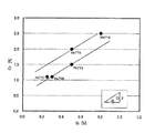
具体的には、母材のC含有量が0.25%で、0.3mm位置硬さがHv硬さで700を超え720以下である鋼、すなわち鋼B、鋼E、鋼M、鋼Nおよび鋼Pについて、そのCr含有量を縦軸に、Si含有量を横軸にとって図3に整理した。なお、図3中の縦軸および横軸の「%」は「質量%」を表す。 Specifically, a steel having a C content of 0.25% and a 0.3 mm position hardness of more than 700 and not more than 720 in terms of Hv hardness, that is, steel B, steel E, steel M, steel N 3 and Steel P are arranged in FIG. 3 with the Cr content on the vertical axis and the Si content on the horizontal axis. In addition, “%” on the vertical axis and the horizontal axis in FIG. 3 represents “mass%”.
その結果、図3から、0.3mm位置硬さがHv硬さで700を超え720以下の鋼の場合、ほぼ〔Cr/Si=2〕の勾配上にプロットされることがわかった。 As a result, it was found from FIG. 3 that the steel having a 0.3 mm position hardness of more than 700 and 720 or less in Hv hardness is plotted on a gradient of [Cr / Si = 2].
つまり、同じC含有量であれば、0.3mm位置硬さは、〔Fn1=Cr−2×Si〕の値で規定できることがわかった。なお、上記のFn1の式におけるCrとSiはそれぞれ、母材に含まれる質量%でのCrとSiの量である。 That is, it was found that the 0.3 mm position hardness can be defined by the value of [Fn1 = Cr-2 × Si] if the C content is the same. Note that Cr and Si in the above formula of Fn1 are the amounts of Cr and Si in mass% contained in the base material, respectively.
そこで次に、質量%での母材のC含有量が0.25%である鋼、すなわち鋼B、鋼D〜G、鋼J〜Qおよび鋼Uについて、0.3mm位置硬さを縦軸に、上記の〔Cr−2×Si〕の値を横軸にとって図4に整理した。なお、図4において横軸の「%」は「質量%」を表す。 Then, next, regarding steel whose C content of the base material in mass% is 0.25%, that is, steel B, steel D to G, steel J to Q, and steel U, the 0.3 mm position hardness is plotted on the vertical axis. Further, the above [Cr-2 × Si] values are arranged in FIG. In FIG. 4, “%” on the horizontal axis represents “mass%”.
その結果、図4から、0.3mm位置硬さと〔Cr−2×Si〕の値はほぼ比例関係にあり、0.3mm位置硬さ、つまり、表面からの深さ0.3mm位置におけるHv硬さが700を上回るためには、〔Fn1=Cr−2×Si〕の値は0.4を上回ればよいことがわかった。 As a result, from FIG. 4, the 0.3 mm position hardness and the value of [Cr−2 × Si] are substantially proportional, and the 0.3 mm position hardness, that is, the Hv hardness at the depth of 0.3 mm from the surface. In order to exceed 700, it was found that the value of [Fn1 = Cr-2 × Si] should exceed 0.4.
低サイクル曲げ疲労強度に関しては、次の検討を実施した。 Regarding the low cycle bending fatigue strength, the following investigation was conducted.
すなわち、前記のガス浸炭焼入れを施した四点曲げ試験片を用いて、その切欠部に常に引張応力がかかるように、応力比0.1、周波数5Hzの条件で一定の曲げ荷重を繰返し負荷し、試験片が破断した時の繰返し回数を調査した。そして、上記曲げ荷重の値を変えた試験を行ってSN曲線を求め、104回で破断する曲げ荷重を低サイクル曲げ疲労強度として評価した。 That is, using the four-point bending test piece subjected to gas carburizing and quenching, a constant bending load was repeatedly applied under the conditions of a stress ratio of 0.1 and a frequency of 5 Hz so that a tensile stress was always applied to the notch. The number of repetitions when the test piece broke was investigated. Then, an SN curve was obtained by performing a test in which the value of the bending load was changed, and the bending load breaking at 10 4 times was evaluated as the low cycle bending fatigue strength.
また、ガス浸炭焼入れを施した四点曲げ試験片を端部から20mm位置で横断し、芯部硬さの測定およびミクロ組織観察を行った。芯部硬さの測定にはマイクロビッカース硬度計を使用し、試験力を4.9Nとして3点測定し、算術平均した。
Further, a four-point bending test piece subjected to gas carburizing and quenching was traversed at a
上記のようにして測定した芯部硬さと低サイクル曲げ疲労強度を前記表2に併せて示した。 Table 2 shows the core hardness and low cycle bending fatigue strength measured as described above.
また、図5に、前記表1に示した各鋼種について芯部硬さと低サイクル曲げ疲労強度の関係を整理して示す。 FIG. 5 shows the relationship between the core hardness and the low cycle bending fatigue strength for each steel type shown in Table 1.
表2中の鋼A〜Cの比較から、0.3mm位置硬さと同様に、芯部硬さ度も母材のC含有量が高くなるにつれ硬くなり、それに伴って低サイクル曲げ疲労強度も増大することがわかる。 From the comparison of steels A to C in Table 2, as with the 0.3 mm position hardness, the core hardness becomes harder as the C content of the base material increases, and the low cycle bending fatigue strength increases accordingly. I understand that
また、図5から、「白三角」印と「黒四角」印の3点を除き、概ね低サイクル曲げ疲労強度は芯部硬さと直線関係をとることがわかる。すなわち、低サイクル曲げ疲労強度の向上のためには、芯部の硬さを高くすることが必要である。 Further, from FIG. 5, it can be seen that the low cycle bending fatigue strength generally has a linear relationship with the core hardness except for the three points “white triangle” and “black square”. That is, in order to improve the low cycle bending fatigue strength, it is necessary to increase the hardness of the core.
しかしながら、上述のとおり図5には直線関係から外れる3点が存在するため、前記の芯部硬さを測定した試験片を鏡面研磨した後、ナイタールで腐食して、芯部のミクロ組織を観察した。なお、前記表2に、芯部のミクロ組織観察結果を併せて示す。 However, as described above, there are three points in FIG. 5 that deviate from the linear relationship. Therefore, the test piece whose core hardness was measured was mirror-polished and then corroded with nital to observe the microstructure of the core. did. Table 2 also shows the results of observation of the microstructure of the core.
さらに表層を観察したところ、鋼Uでは粒界にそって析出物が観察された。このため、EPMA(電子線マイクロアナライザ)を使って当該部位を分析した。その結果、析出物にはCおよびCrが濃化していることが確認でき、Cr炭化物であることがわかった。 When the surface layer was further observed, precipitates were observed along the grain boundaries in Steel U. For this reason, the said site | part was analyzed using EPMA (electron beam microanalyzer). As a result, it was confirmed that C and Cr were concentrated in the precipitate, and it was found to be Cr carbide.
これらのミクロ観察の結果、以下の事項が明らかになった。 As a result of these micro observations, the following matters became clear.
先ず第1に、図5において「黒四角」印で示すものは鋼Uで、き裂発生と同時に破断したものであり、上述のとおり粒界にCr炭化物が生成していた。 First, in FIG. 5, what is indicated by “black squares” is steel U, which was broken at the same time as cracks were generated, and Cr carbide was generated at the grain boundaries as described above.
すなわち、粒界にCr炭化物が生成すると低サイクル曲げ疲労強度が著しく低下する。したがって、Cr炭化物の生成を抑制する必要がある。 That is, when Cr carbide is generated at the grain boundary, the low cycle bending fatigue strength is significantly reduced. Therefore, it is necessary to suppress the formation of Cr carbide.
なお、Cr炭化物の生成は、鋼中のCr含有量のみに依存するものではなく、Si含有量にも影響を受ける。すなわち、Siは鋼中のCの活量を増大させることにより浸炭時の表面C濃度を低下させる作用を有することから、SiにはCr炭化物の生成を抑制する効果がある。そして、このようなCr炭化物は、前述した〔Cr−2×Si〕の値が2.00の鋼Uで認められ、〔Cr−2×Si〕の値が1.50の鋼Oでは認められなかったことから、〔Fn1=Cr−2×Si〕の値は1.8以下にする必要があることがわかった。 In addition, the production | generation of Cr carbide is not dependent only on Cr content in steel, but is influenced also by Si content. That is, since Si has the effect of reducing the surface C concentration during carburizing by increasing the activity of C in the steel, Si has the effect of suppressing the formation of Cr carbides. Such Cr carbide is recognized in the steel U having the value of [Cr-2 × Si] of 2.00 and the steel O having a value of [Cr-2 × Si] of 1.50. It was found that the value of [Fn1 = Cr-2 × Si] needs to be 1.8 or less.
第2に、図5中に「白三角」印で示すものは鋼Hと鋼Tで、芯部組織がフェライトとマルテンサイトの二相組織になっていた。すなわち、芯部に軟質なフェライトが生成すると低サイクル曲げ疲労強度が著しく低下する。したがって、芯部のフェライト生成を抑制する必要がある。 Secondly, what is indicated by “white triangles” in FIG. 5 is steel H and steel T, and the core structure is a two-phase structure of ferrite and martensite. That is, when soft ferrite is generated in the core, the low cycle bending fatigue strength is significantly reduced. Therefore, it is necessary to suppress the formation of ferrite in the core.
なお、芯部のフェライトは、浸炭処理中に、オーステナイト単相領域から、フェライトとオーステナイトの二相領域になることで生じる。したがって、フェライトの生成を抑制するためには、鋼のA3点を低くすればよい。 In addition, the ferrite of a core part arises from the austenite single phase area | region during a carburizing process, becoming a two phase area | region of a ferrite and austenite. Therefore, in order to suppress the formation of ferrite, it is sufficient to lower the three point A of the steel.
なお、本発明の重要な元素であるSiは、A3点を上昇させる元素である。このため、Si含有量が高い場合であっても、A3点が浸炭処理温度以下となるように母材を成分設計する必要がある。 Si, which is an important element of the present invention, is an element that raises the A 3 point. Therefore, even when the Si content is high, it is necessary to A 3 point to component design preform so as not to exceed the carburizing temperature.
そこで、AndrewsがJ.Iron Steel Inst.、203(1965)、p.721で報告しているA3点の式をベースに、Siの影響を定数項に取り込んで、表1の鋼について、〔Fn2=959−(203×C0.5+30×Mn)〕の値を計算した。なお、上記のFn2の式におけるCとMnはそれぞれ、母材に含まれる質量%でのCとMnの量である。 Therefore, Andrews Iron Steel Inst. 203 (1965), p. Based on equation A 3 points are reported in 721, captures the effects of Si on the constant term, for the Table 1 Steel, calculate the value of [Fn2 = 959- (203 × C 0.5 + 30 × Mn) ] did. Note that C and Mn in the above formula of Fn2 are respectively the amounts of C and Mn in mass% contained in the base material.
その結果、芯部のフェライトは、前述した〔959−(203×C0.5+30×Mn)〕の値が856の鋼Hと850の鋼Tで認められ、〔959−(203×C0.5+30×Mn)〕の値が844の鋼Aでは認められなかったたことから、芯部におけるフェライトの生成を抑制するためには、上記Fn2の値を850未満にすればよいことがわかった。 As a result, the ferrite of the core part was recognized in the steel H of 856 and the steel T of 850 having the value of [959− ( 203 × C 0.5 + 30 × Mn ) ], and [959− ( 203 × C 0.5 + 30 ×]. Since the value of Mn ) ] was not observed in steel A of 844, it was found that the value of Fn2 should be less than 850 in order to suppress the formation of ferrite in the core.
第3に、図5に示すように、低サイクル曲げ疲労強度と芯部硬さが直線関係を示す場合でも、最小自乗直線を境として、概ねその上下の2つの群に分かれることが明らかになった。 Thirdly, as shown in FIG. 5, even when the low cycle bending fatigue strength and the core hardness show a linear relationship, it is clear that they are roughly divided into two groups above and below the least square line as a boundary. It was.
そこで、低サイクル曲げ疲労強度と芯部硬さが直線関係を示す各鋼種についてさらに詳細に調査したところ、表層の粒界酸化層深さが低サイクル曲げ疲労強度に影響することがわかった。 Accordingly, when the steel types having a linear relationship between the low cycle bending fatigue strength and the core hardness were investigated in more detail, it was found that the grain boundary oxide depth of the surface layer affects the low cycle bending fatigue strength.
すなわち、図5において、「白丸」印は粒界酸化層深さが20μm以下の鋼であり、一方、「黒丸」印は粒界酸化層深さが20μmを超える鋼である。そして、図5から、粒界酸化層深さが20μm以下の鋼と粒界酸化層深さが20μmを超える鋼とは、最小自乗直線を境として概ねその直線の上下に分かれ、粒界酸化層深さが大きくなると低サイクル曲げ疲労強度は低下する傾向があり、粒界酸化層深さを20μm以下にする方が高い低サイクル曲げ疲労強度を得られることが明らかになった。 That is, in FIG. 5, the “white circle” mark is a steel having a grain boundary oxide layer depth of 20 μm or less, while the “black circle” mark is a steel having a grain boundary oxide layer depth of more than 20 μm. From FIG. 5, the steel having a grain boundary oxide layer depth of 20 μm or less and the steel having a grain boundary oxide layer depth of more than 20 μm are roughly divided above and below the straight line with a least square line as a boundary. It has been clarified that the low cycle bending fatigue strength tends to decrease as the depth increases, and that a higher low cycle bending fatigue strength can be obtained when the grain boundary oxide layer depth is 20 μm or less.
そこで、次に、新たに16鋼種溶製して、既に述べたのと同様の処理を行って、粒界酸化層深さとSi、CrおよびMnの含有量との関係を種々調査した。 Therefore, next, 16 steel types were melted and the same treatment as described above was performed, and various relationships between the grain boundary oxide layer depth and the contents of Si, Cr and Mn were investigated.
その結果、図6および図7のように整理できることがわかった。なお、図6および図7における横軸の「%」は「質量%」を表す。 As a result, it turned out that it can arrange | position like FIG. 6 and FIG. In FIG. 6 and FIG. 7, “%” on the horizontal axis represents “mass%”.
すなわち、質量%でのSiとCrの含有量の和である〔Si+Cr〕の値が0.5〜3.5の範囲では、図6に示すように、その値とともに粒界酸化層深さは浅くなり、粒界酸化層深さをyとすれば、
y=−10×(Si+Cr)+19
の式で表すことができ、また、質量%でのMnの含有量が0.3〜2.2%の範囲では、図7に示すように、その含有量とともに粒界酸化層深さは深くなり、粒界酸化層深さをyとすれば、
y=7×Mn−1
の式で表すことができることがわかった。
That is, when the value of [Si + Cr], which is the sum of the contents of Si and Cr in mass%, is in the range of 0.5 to 3.5, as shown in FIG. If it becomes shallower and the grain boundary oxide layer depth is y,
y = −10 × (Si + Cr ) +19
In addition, when the content of Mn in mass% is in the range of 0.3 to 2.2%, as shown in FIG. 7, the grain boundary oxide layer depth is deep with the content. If the grain boundary oxide layer depth is y,
y = 7 × Mn−1
It was found that it can be expressed by the following formula.
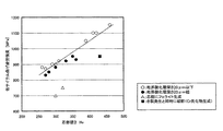
そこで、上記の結果を線形結合し、〔Fn3=7×Mn−10×(Si+Cr−1.8)〕というパラメータで、粒界酸化層深さとの関係を整理すると、Siが0.25%以上の範囲では、図8に示すようになった。 Therefore, when the above results are linearly combined and the relationship with the grain boundary oxide layer depth is arranged with the parameter [Fn3 = 7 × Mn−10 × (Si + Cr−1.8)], Si is 0.25% or more. In this range, it became as shown in FIG.
なお、図8中の「白丸」印は、粒界酸化層深さが20μm以下のもの、「黒丸」印は粒界酸化層深さが20μmを超えるものを示す。そして、この図8から、Fn3の値を8以下とすることで、粒界酸化層深さを20μm以下にすることができ、低サイクル曲げ疲労強度を向上できることがわかった。 In FIG. 8, the “white circle” mark indicates that the grain boundary oxide layer depth is 20 μm or less, and the “black circle” mark indicates that the grain boundary oxide layer depth exceeds 20 μm. From FIG. 8, it was found that by setting the value of Fn3 to 8 or less, the grain boundary oxide layer depth can be set to 20 μm or less, and the low cycle bending fatigue strength can be improved.
本発明は、上記の知見に基づいて完成されたものであり、その要旨は、下記(1)〜(3)に示す動力伝達部品用肌焼鋼にある。 This invention is completed based on said knowledge, The summary exists in the case hardening steel for power transmission components shown to following (1)-(3).
(1)質量%で、C:0.15〜0.35%、Si:0.40〜1.10%、Mn:0.50〜1.50%、S:0.01〜0.05%、Cr:1.20〜2.60%、Al:0.010〜0.050%およびN:0.010〜0.025%を含有するとともに、C、Si、MnおよびCrの含有量が、下記の(1)〜(3)式で表されるFn1〜Fn3の値でそれぞれ、0.4<Fn1≦1.8、Fn2<850およびFn3≦8を満たし、残部はFeおよび不純物からなり、不純物中のP、Cu、NiおよびVがそれぞれ、P:0.05%以下、Cu:0.10%以下、Ni:0.10%以下およびV:0.005%以下であることを特徴とする動力伝達部品用肌焼鋼。
Fn1=Cr−2×Si・・・(1)、
Fn2=959−(203×C0.5+30×Mn)・・・(2)、
Fn3=7×Mn−10×(Si+Cr−1.8)・・・(3)。
ここで、(1)〜(3)式中の元素記号は、その元素の質量%での含有量を表す。
(1) By mass%, C: 0.15 to 0.35%, Si: 0.40 to 1.10%, Mn: 0.50 to 1.50%, S: 0.01 to 0.05% , Cr: 1.20 to 2.60%, Al: 0.010 to 0.050% and N: 0.010 to 0.025%, and the contents of C, Si, Mn and Cr are The values of Fn1 to Fn3 represented by the following formulas (1) to (3) satisfy 0.4 <Fn1 ≦ 1.8, Fn2 <850 and Fn3 ≦ 8, respectively, and the balance is made of Fe and impurities. P, Cu, Ni and V in the impurities are respectively P: 0.05% or less, Cu: 0.10% or less, Ni: 0.10% or less and V: 0.005% or less. Hardened steel for power transmission parts.
Fn1 = Cr-2 × Si (1),
Fn2 = 959− ( 203 × C 0.5 + 30 × Mn ) (2),
Fn3 = 7 * Mn-10 * (Si + Cr-1.8) ... (3).
Here, the element symbol in the formulas (1) to (3) represents the content in mass% of the element.
(2)Feの一部に代えて、質量%で、Mo:0.40%以下を含有することを特徴とする上記(1)に記載の動力伝達部品用肌焼鋼。 (2) The case-hardened steel for power transmission parts as described in (1) above, which contains Mo: 0.40% or less in mass% instead of part of Fe.
(3)Feの一部に代えて、質量%で、Ti:0.10%以下およびNb:0.10%以下のうちの1種または2種を含有することを特徴とする上記(1)または(2)に記載の動力伝達部品用肌焼鋼。 (3) The above (1), characterized in that, instead of a part of Fe, by mass%, one or two of Ti: 0.10% or less and Nb: 0.10% or less are contained. Or the case hardening steel for power transmission components as described in (2).
以下、上記 (1)〜(3)の動力伝達部品用肌焼鋼に係る発明を、それぞれ、「本発明(1)」〜「本発明(3)」という。また、総称して「本発明」ということがある。 Hereinafter, the inventions related to the case-hardening steel for power transmission parts (1) to (3) are referred to as “present invention (1)” to “present invention (3)”, respectively. Also, it may be collectively referred to as “the present invention”.
本発明の動力伝達部品用肌焼鋼を用いれば、ピッチング強度、スポーリング強度および低サイクル曲げ疲労強度の全てにおいて良好な特性を有する動力伝達部品を得ることができる。 By using the case-hardened steel for power transmission parts of the present invention, a power transmission part having good characteristics in all of pitching strength, spalling strength and low cycle bending fatigue strength can be obtained.
以下、本発明の各要件について詳しく説明する。なお、化学成分の含有量の「%」は「質量%」を意味する。 Hereinafter, each requirement of the present invention will be described in detail. In addition, “%” of the content of the chemical component means “mass%”.
C:0.15〜0.35%
Cは、浸炭深さを増大し、さらに0.3mm位置の硬さと浸炭焼入れ時の芯部硬さを増大してスポーリング強度と低サイクル曲げ疲労強度を向上させるために重要な元素である。しかしながら、Cの含有量が0.15%未満では浸炭深さの増大および低サイクル曲げ疲労強度の向上効果が小さい。一方、その含有量が0.35%を超えると芯部の靱性が低下するため、き裂発生と同時に破断して低サイクル曲げ疲労強度が劣化する。したがって、Cの含有量を0.15〜0.35%とした。C含有量の望ましい範囲は0.20〜0.30%である。
C: 0.15-0.35%
C is an important element for improving the spalling strength and the low cycle bending fatigue strength by increasing the carburizing depth and further increasing the hardness at the 0.3 mm position and the core hardness during carburizing and quenching. However, if the C content is less than 0.15%, the effect of increasing the carburization depth and improving the low cycle bending fatigue strength is small. On the other hand, if the content exceeds 0.35%, the toughness of the core portion decreases, so that fracture occurs at the same time as cracking, and low cycle bending fatigue strength deteriorates. Therefore, the content of C is set to 0.15 to 0.35%. A desirable range for the C content is 0.20 to 0.30%.
なお、Cの含有量は上記の範囲において、前記の(2)式で表されるFn2の値がFn2<850をも満たす必要がある。 In addition, in the content of C in the above range, the value of Fn2 represented by the above formula (2) needs to satisfy Fn2 <850.
Si:0.40〜1.10%
Siは、300℃程度での焼戻し軟化抵抗を上昇させるために重要な元素である。Siの含有量が0.40%を下回ると上記の効果が小さく面圧強度(ピッチング強度)が低下する。しかしながら、Siは浸炭時のオーステナイト中のCの活量を上げる元素でもあるため、1.10%を超えて含有すると浸炭性が著しく劣化する。したがって、Siの含有量を0.40〜1.10%とした。Si含有量の望ましい範囲は0.45〜0.90%である。
Si: 0.40 to 1.10%
Si is an important element for increasing the temper softening resistance at about 300 ° C. When the Si content is less than 0.40%, the above effect is small and the surface pressure strength (pitching strength) is lowered. However, since Si is also an element that increases the activity of C in the austenite during carburizing, if it exceeds 1.10%, the carburizing property is remarkably deteriorated. Therefore, the Si content is set to 0.40 to 1.10%. The desirable range of Si content is 0.45 to 0.90%.
なお、Siの含有量は上記の範囲において、前記の(1)式および(3)式で表されるFn1およびFn3の値がそれぞれ、0.4<Fn1≦1.8およびFn3≦8をも満たす必要がある。 The Si content is within the above range, and the values of Fn1 and Fn3 represented by the above formulas (1) and (3) satisfy 0.4 <Fn1 ≦ 1.8 and Fn3 ≦ 8, respectively. It is necessary to satisfy.
Mn:0.50〜1.50%
Mnは、浸炭時のオーステナイト中のCの活量を下げ、浸炭を促進する元素であると同時にMnSを形成し被削性を高める元素である。しかしながら、Mnの含有量が0.50%を下回る場合には前記の効果が小さい。一方、Mnを1.50%を超えて含有すると前記の効果が飽和するばかりでなく、焼準後の硬度が上昇する結果、被削性が著しく劣化する。したがって、Mnの含有量を0.50〜1.50%とした。Mn含有量の望ましい範囲は0.60〜1.20%である。
Mn: 0.50 to 1.50%
Mn is an element that lowers the activity of C in the austenite during carburizing and promotes carburizing, and at the same time forms MnS and increases machinability. However, when the Mn content is less than 0.50%, the above effect is small. On the other hand, when Mn exceeds 1.50%, not only the above effects are saturated, but also the hardness after normalization increases, and as a result, the machinability is significantly deteriorated. Therefore, the Mn content is set to 0.50 to 1.50%. A desirable range of the Mn content is 0.60 to 1.20%.
なお、Mnの含有量は上記の範囲において、前記の(2)式および(3)式で表されるFn2およびFn3の値がそれぞれ、Fn2<850およびFn3≦8をも満たす必要がある。 In addition, the content of Mn needs to satisfy Fn2 <850 and Fn3 ≦ 8, respectively, in the values within the above range, the values of Fn2 and Fn3 represented by the above formulas (2) and (3).
S:0.01〜0.05%
Sは、MnとともにMnSを形成するための必須元素である。一定量のMnを含有させた状態で形成されるMnSは被削性を確保するために必要である。この効果を得るためには、Sの含有量は0.01%以上とする必要がある。しかしながら、Sの含有量が過剰になると熱間延性が低下し、特に、その含有量が0.05%を超えると、熱間延性の低下が著しくなる。したがって、Sの含有量を0.01〜0.05%とした。なお、Sの含有量は0.01〜0.03%とすることが好ましい。
S: 0.01 to 0.05%
S is an essential element for forming MnS together with Mn. MnS formed in a state where a certain amount of Mn is contained is necessary for ensuring machinability. In order to obtain this effect, the S content needs to be 0.01% or more. However, when the S content is excessive, the hot ductility is lowered, and particularly when the content exceeds 0.05%, the hot ductility is significantly lowered. Therefore, the content of S is set to 0.01 to 0.05%. In addition, it is preferable that content of S shall be 0.01-0.03%.
Cr:1.20〜2.60%
Crは、浸炭時のオーステナイト中のCの活量を下げ、浸炭を促進する元素である。しかしながら、Crの含有量が1.20%を下回る場合には前記の効果が小さい。一方、Crを2.60%を超えて含有すると浸炭時に粒界にCr炭化物を生成しやすくなり、低サイクル曲げ疲労強度を低下させる。したがって、Crの含有量を1.20〜2.60%とした。Cr含有量の望ましい範囲は1.30〜2.30%であり、さらに望ましい範囲は1.50〜2.00%である。
Cr: 1.20 to 2.60%
Cr is an element that lowers the activity of C in the austenite during carburizing and promotes carburizing. However, when the Cr content is less than 1.20%, the above effect is small. On the other hand, when Cr is contained in excess of 2.60%, it becomes easy to produce Cr carbide at the grain boundary during carburizing, and lowers the low cycle bending fatigue strength. Therefore, the content of Cr is set to 1.20 to 2.60%. A desirable range of the Cr content is 1.30 to 2.30%, and a more desirable range is 1.50 to 2.00%.
なお、Crの含有量は上記の範囲において、前記の(1)式で表されるFn1値が、0.4<Fn1≦1.8をも満たす必要がある。 In addition, Cr content needs to satisfy | fill 0.4 <Fn1 <= 1.8 also in Fn1 value represented by said Formula (1) in said range.
Al:0.010〜0.050%
Alは、鋼中のNと結合しAlNを形成し、浸炭中の結晶粒を微細化することにより、浸炭層の靱性を向上させる作用がある。この効果を得るためには、Alは少なくとも0.010%の含有量が必要である。しかしながら、Alの含有量が0.050%を超えると、硬質のAl2O3形成による被削性の劣化をきたす。したがって、Alの含有量を0.010〜0.050%とした。なお、Alの含有量は0.010〜0.040%とすることが好ましい。
Al: 0.010 to 0.050%
Al combines with N in steel to form AlN, and has the effect of improving the toughness of the carburized layer by refining crystal grains during carburization. In order to obtain this effect, the Al content needs to be at least 0.010%. However, if the Al content exceeds 0.050%, the machinability deteriorates due to the formation of hard Al 2 O 3 . Therefore, the content of Al is set to 0.010 to 0.050%. In addition, it is preferable that content of Al shall be 0.010 to 0.040%.
N:0.010〜0.025%
Nは、Alと結合してAlNを形成し、浸炭中の結晶粒を微細化することにより、浸炭層の靱性を向上させる作用がある。この効果を得るためには、Nは少なくとも0.010%の含有量が必要である。しかしながら、0.025%を超えて含有させても、上記の効果が飽和するとともに、溶製の際、内部にいわゆる「巣」ができやすくなる。したがって、Nの含有量を、0.010〜0.025%とした。N含有量の望ましい範囲は0.012〜0.020%である。
N: 0.010 to 0.025%
N combines with Al to form AlN and refines crystal grains during carburizing, thereby improving the toughness of the carburized layer. In order to obtain this effect, N must have a content of at least 0.010%. However, even if the content exceeds 0.025%, the above effect is saturated, and a so-called “nest” is easily formed in the interior during melting. Therefore, the N content is set to 0.010 to 0.025%. A desirable range of the N content is 0.012 to 0.020%.
Fn1の値:0.4を超えて1.8以下
上述のとおり、Siは焼戻し軟化抵抗の上昇のために重要な元素であり、Crは浸炭の促進のために重要な元素である。しかしながら、前記の(1)式で表されるFn1の値が0.4以下の場合には浸炭性の劣化が著しくなるため、0.3mm位置硬さをHv硬さで700以上にすることができず、スポーリング強度が低下する。一方、Fn1の値が1.8を上回ると、粒界のCr炭化物の生成量が増加して低サイクル曲げ疲労強度の低下を招く。したがって、前記の(1)式、つまり〔Fn1=Cr−2×Si〕で表されるFn1の値が、0.4<Fn1≦1.8を満たすこととした。なお、Fn1の値は、0.5≦Fn1≦1.5とすることが望ましく、さらに望ましい範囲は、0.6≦Fn1≦1.2である。
Fn1 value: more than 0.4 and 1.8 or less As described above, Si is an important element for increasing the temper softening resistance, and Cr is an important element for promoting carburization. However, when the value of Fn1 represented by the above formula (1) is 0.4 or less, the carburizing property is remarkably deteriorated. Therefore, the 0.3 mm position hardness is set to 700 or more in terms of Hv hardness. It is not possible to reduce the spalling strength. On the other hand, if the value of Fn1 exceeds 1.8, the amount of Cr carbide generated at the grain boundaries increases, leading to a decrease in low cycle bending fatigue strength. Therefore, the value of Fn1 represented by the above equation (1), that is, [Fn1 = Cr−2 × Si] is set to satisfy 0.4 <Fn1 ≦ 1.8. Note that the value of Fn1 is desirably 0.5 ≦ Fn1 ≦ 1.5, and a more desirable range is 0.6 ≦ Fn1 ≦ 1.2.
Fn2の値:850未満
C、SiおよびMnの含有量は鋼のA3点に影響を与える。A3点が上昇すると浸炭処理時に芯部にフェライト相が生成するため、焼入れ後も芯部がフェライトとマルテンサイトの二相組織となり、低サイクル曲げ疲労強度が劣化する。本発明は、A3点を上昇させるものの焼戻し軟化抵抗を高める効果を有するSiを積極的に活用するので、A3点の制御のためには、CおよびMnの含有量を制御する必要がある。そして、前記の(2)式で表されるFn2の値が850以上の場合には、芯部にフェライトが生成して低サイクル曲げ疲労強度が低下する。このため、前記の(2)式、つまり〔Fn2=959−(203×C0.5+30×Mn)〕で表されるFn2の値が、Fn2<850を満たすこととした。なお、Fn2の値はFn2≦840とすることが望ましい。
Fn2 values: the content of 850 less than C, Si and Mn affects three points A steel. Since the A 3 point is a ferrite phase is generated in the core during the carburizing to rise, after quenching is also the core portion is a two-phase structure of ferrite and martensite, low cycle bending fatigue strength deteriorates. The present invention, since the active use of Si having an effect of increasing temper softening resistance which increases the three points A, for the control of A 3-point, it is necessary to control the content of C and Mn . And when the value of Fn2 represented by said Formula (2) is 850 or more, a ferrite produces | generates in a core part and low cycle bending fatigue strength falls. For this reason, the value of Fn2 represented by the above formula (2), that is, [Fn2 = 959− ( 203 × C 0.5 + 30 × Mn ) ] is determined to satisfy Fn2 <850. The value of Fn2 is preferably Fn2 ≦ 840.
Fn3の値:8以下
Mn、SiおよびCrはいずれもガス浸炭時の粒界酸化層深さに影響を与える。前記の(3)式で表されるFn3の値が8を上回ると、Mnの影響により粒界酸化層深さが深くなり、低サイクル曲げ疲労強度が劣化する。したがって、前記の(3)式、つまり〔Fn3=7×Mn−10×(Si+Cr−1.8)〕で表されるFn3の値が、Fn3≦8を満たすこととした。なお、Fn3の値はFn3≦5.0とすることが望ましい。
Fn3 value: 8 or less Mn, Si and Cr all affect the grain boundary oxide layer depth during gas carburization. If the value of Fn3 represented by the above formula (3) exceeds 8, the grain boundary oxide layer depth becomes deep due to the effect of Mn, and the low cycle bending fatigue strength deteriorates. Therefore, the value of Fn3 represented by the above equation (3), that is, [Fn3 = 7 × Mn−10 × (Si + Cr−1.8)] satisfies Fn3 ≦ 8. The value of Fn3 is preferably Fn3 ≦ 5.0.
本発明においては、不純物中のP、Cu、NiおよびVは、その含有量をそれぞれ、特定の値以下に制限する必要がある。以下、このことについて説明する。 In the present invention, it is necessary to limit the contents of P, Cu, Ni, and V in the impurity to a specific value or less. This will be described below.
P:0.05%以下
本発明においては、Pは不純物としてその含有量を0.05%以下に抑えなくてはならない。すなわち、Pは、熱間延性の低下を招き、特に、その含有量が0.05%を超えると、熱間延性の低下が著しくなる。したがって、本発明においては、不純物中のPの含有量を0.05%以下とした。なお、不純物中のPの含有量は0.03%以下とすることが好ましい。
P: 0.05% or less In the present invention, the content of P as an impurity must be suppressed to 0.05% or less. That is, P causes a decrease in hot ductility, and particularly when its content exceeds 0.05%, the decrease in hot ductility becomes significant. Therefore, in the present invention, the content of P in the impurities is set to 0.05% or less. In addition, it is preferable that content of P in an impurity shall be 0.03% or less.
Cu:0.10%以下
本発明においては、Cuは不純物としてその含有量を0.10%以下に抑えなくてはならない。Cuは、浸炭時のオーステナイト中のCの活量を上げ、0.3mm位置硬さの増大を妨げ、スポーリング強度を低下させる。特に、Cuの含有量が0.10%を超えるとその影響が顕著である。したがって、本発明においては、不純物中のCuの含有量を0.10%以下とした。なお、不純物中のCuの含有量は0.05%以下とすることが好ましい。
Cu: 0.10% or less In the present invention, the content of Cu as an impurity must be suppressed to 0.10% or less. Cu raises the activity of C in the austenite at the time of carburizing, prevents an increase in 0.3 mm position hardness, and lowers the spalling strength. In particular, when the Cu content exceeds 0.10%, the influence is remarkable. Therefore, in the present invention, the content of Cu in the impurities is set to 0.10% or less. In addition, it is preferable that content of Cu in an impurity shall be 0.05% or less.
Ni:0.10%以下
本発明においては、NiはCuと同様に不純物としてその含有量を0.10%以下に抑えなくてはならない。Niは、浸炭時のオーステナイト中のCの活量を上げ、0.3mm位置硬さの増大を妨げ、スポーリング強度を低下させる。特に、その含有量が0.10%を超えるとその影響が顕著である。したがって、本発明においては、不純物中のNiの含有量を0.10%以下とした。なお、不純物中のNiの含有量は0.05%以下とすることが好ましい。
Ni: 0.10% or less In the present invention, Ni must be contained as an impurity in the same manner as Cu, and its content must be suppressed to 0.10% or less. Ni raises the activity of C in the austenite at the time of carburizing, prevents an increase in 0.3 mm position hardness, and lowers the spalling strength. In particular, when the content exceeds 0.10%, the influence is remarkable. Therefore, in the present invention, the content of Ni in the impurities is set to 0.10% or less. In addition, it is preferable that content of Ni in an impurity shall be 0.05% or less.
V:0.005%以下
本発明においては、Vは不純物としてその含有量を0.005%以下に抑えなくてはならない。すなわち、Vは、CやNと結合しVCやVCNを形成し、これらの炭化物や炭窒化物は浸炭処理の昇温過程の初期にはオーステナイト粒を微細化するのに有効であるものの、かえって結晶粒が小さくなりすぎ、結晶粒成長の駆動力が大きくなりすぎて、異常粒成長の要因となる。特に、Vの含有量が0.005%を超えると、異常粒成長が顕著になり、低サイクル曲げ疲労強度が低下する。したがって、本発明においては、不純物中のVの含有量を0.005%以下とした。
V: 0.005% or less In the present invention, the content of V as an impurity must be suppressed to 0.005% or less. That is, V combines with C and N to form VC and VCN, and these carbides and carbonitrides are effective in refining austenite grains at the beginning of the temperature raising process of the carburizing process, but on the contrary The crystal grains become too small and the driving force for crystal grain growth becomes too large, causing abnormal grain growth. In particular, when the V content exceeds 0.005%, abnormal grain growth becomes remarkable, and the low cycle bending fatigue strength decreases. Therefore, in the present invention, the content of V in the impurities is set to 0.005% or less.
上記の理由から、本発明(1)に係る動力伝達部品用肌焼鋼は、C:0.15〜0.35%、Si:0.40〜1.10%、Mn:0.50〜1.50%、S:0.01〜0.05%、Cr:1.20〜2.60%、Al:0.010〜0.050%およびN:0.010〜0.025%を含有するとともに、C、Si、MnおよびCrの含有量が、前記の(1)〜(3)式で表されるFn1〜Fn3の値でそれぞれ、0.4<Fn1≦1.8、Fn2<850およびFn3≦8を満たし、残部はFeおよび不純物からなり、不純物中のP、Cu、NiおよびVがそれぞれ、P:0.05%以下、Cu:0.10%以下、Ni:0.10%以下およびV:0.005%以下であることと規定した。 For the above reasons, the case-hardening steel for power transmission parts according to the present invention (1) has C: 0.15-0.35%, Si: 0.40-1.10%, Mn: 0.50-1 .50%, S: 0.01 to 0.05%, Cr: 1.20 to 2.60%, Al: 0.010 to 0.050% and N: 0.010 to 0.025% In addition, the contents of C, Si, Mn, and Cr are 0.4 <Fn1 ≦ 1.8, Fn2 <850, and Fn1 to Fn3 represented by the above formulas (1) to (3), respectively. Fn3 ≦ 8 is satisfied, the balance is made of Fe and impurities, and P, Cu, Ni and V in the impurities are respectively P: 0.05% or less, Cu: 0.10% or less, Ni: 0.10% or less And V: specified to be 0.005% or less.
なお、本発明(1)に係る動力伝達部品用肌焼鋼は、そのFeの一部に代えて、必要に応じてさらに、
第1群:Mo:0.40%以下、
第2群:Ti:0.10%以下およびNb:0.10%以下のうちの1種または2種、
の各グループの元素の1種以上を選択的に含有させることができる。
In addition, the case-hardened steel for power transmission parts according to the present invention (1) is replaced with a part of the Fe, if necessary,
First group: Mo: 0.40% or less,
2nd group: One or two of Ti: 0.10% or less and Nb: 0.10% or less,
One or more elements of each group can be selectively contained.
すなわち、前記第1群または第2群のいずれかのグループの元素の1種以上を任意元素として含有させてもよい。 That is, one or more of the elements of either the first group or the second group may be included as an arbitrary element.
以下、上記の任意元素に関して説明する。 Hereinafter, the above optional elements will be described.
第1群:Mo:0.40%以下
第1群の元素であるMoは、浸炭層の焼入れ性を高め、面圧強度を向上させる作用を有する。この効果を得るためには、Moの含有量は0.05%以上とすることが好ましい。しかしながら、Moの含有量が0.40%を超えると被削の低下が著しくなる。したがって、Moの含有量は、0.40%以下とした。含有する場合のMoの量は、0.05〜0.40%とすることが好ましく、0.05〜0.30%とすれば一層好ましい。
First group: Mo: 0.40% or less Mo, which is an element of the first group, has an effect of improving the hardenability of the carburized layer and improving the surface pressure strength. In order to obtain this effect, the Mo content is preferably 0.05% or more. However, when the Mo content exceeds 0.40%, the reduction of the machining becomes remarkable. Therefore, the Mo content is set to 0.40% or less. When Mo is contained, the amount of Mo is preferably 0.05 to 0.40%, and more preferably 0.05 to 0.30%.
第2群:Ti:0.10%以下およびNb:0.10%以下のうちの1種または2種
第2群の元素であるTiおよびNbは、浸炭層の靱性を高める作用を有するので、この効果を得るために上記の元素を含有させてもよい。以下、第2群の元素について詳しく説明する。
2nd group: Ti: 0.10% or less and Nb: 0.10% or less, and 2nd group elements Ti and Nb have the effect of increasing the toughness of the carburized layer. In order to acquire this effect, you may contain said element. Hereinafter, the second group of elements will be described in detail.
Ti:0.10%以下
Tiは、鋼中のCおよびNと結合して炭窒化物を形成し、AlNと同様に浸炭時の結晶粒の微細化に効果があり、浸炭層の靱性を向上させる作用がある。こうした効果を得るためには、Tiの含有量は0.005%以上とすることが好ましい。しかしながら、Tiの含有量が0.10%を超えると硬質のTiNを生成し、被削性の低下が著しくなる。したがって、Tiの含有量は、0.10%以下とした。含有する場合のTiの量は、0.005〜0.10%とすることが好ましい。
Ti: 0.10% or less Ti combines with C and N in steel to form carbonitrides, which, like AlN, is effective in refining crystal grains during carburizing and improves the toughness of the carburized layer There is an action to make. In order to obtain such an effect, the Ti content is preferably 0.005% or more. However, when the Ti content exceeds 0.10%, hard TiN is generated, and the machinability is significantly lowered. Therefore, the Ti content is set to 0.10% or less. When Ti is contained, the amount of Ti is preferably 0.005 to 0.10%.
Nb:0.10%以下
NbもTiと同様に、鋼中のCおよびNと結合して炭窒化物を形成し、AlNと同様に浸炭時の結晶粒の微細化に効果があり、浸炭層の靱性を向上させる作用がある。こうした効果を得るためには、Nbの含有量は0.005%以上とすることが好ましい。しかしながら、Nbの含有量が0.10%を超えると粗大な析出物を生成して、逆に異常粒成長が生じやすくなる。したがって、Nbの含有量は、0.10%以下とした。含有する場合のNbの量は、0.005〜0.10%とすることが好ましい。
Nb: 0.10% or less Nb also combines with C and N in steel to form carbonitrides, like Ti, and has the effect of refining crystal grains during carburization, similar to AlN. It has the effect of improving the toughness of the. In order to obtain such effects, the Nb content is preferably 0.005% or more. However, when the Nb content exceeds 0.10%, coarse precipitates are generated, and abnormal grain growth tends to occur. Therefore, the Nb content is 0.10% or less. The content of Nb when contained is preferably 0.005 to 0.10%.
なお、上記のTiおよびNbは、そのうちのいずれか1種のみ、または2種の複合で含有することができる。 In addition, said Ti and Nb can be contained only in any 1 type of them, or 2 types of composites.
上記の理由から、本発明(2)に係る動力伝達部品用肌焼鋼は、本発明(1)に係る動力伝達部品用肌焼鋼のFeの一部に代えて、上記第1群の元素であるMoを含有することと規定した。 For the above reasons, the case hardening steel for power transmission parts according to the present invention (2) is replaced with a part of Fe of the case hardening steel for power transmission parts according to the present invention (1). It was specified that it contained Mo.
また、本発明(3)に係る動力伝達部品用肌焼鋼は、本発明(1)または本発明(2)に係る動力伝達部品用肌焼鋼のFeの一部に代えて、上記第2群の元素であるTiおよびNbのうちの1種または2種を含有することと規定した。 Further, the case hardening steel for power transmission parts according to the present invention (3) is replaced with a part of Fe of the case hardening steel for power transmission parts according to the present invention (1) or the present invention (2). It was defined to contain one or two of Ti and Nb which are group elements.
以下、実施例により本発明をさらに詳しく説明する。 Hereinafter, the present invention will be described in more detail with reference to examples.
表3に示す化学組成を有する鋼1〜22を50kg真空溶解炉によって溶解し、インゴットを作製した。
なお、表3の中の鋼1〜8は、化学組成が本発明で規定する範囲内にある鋼である。一方、鋼9〜22は、化学組成が本発明で規定する条件から外れた比較例の鋼である。この比較例の鋼のうちで鋼9は、JIS G 4053(2003)で規定されたSCM420である。 In addition, the steels 1-8 in Table 3 are steels having a chemical composition within the range defined by the present invention. On the other hand, steels 9 to 22 are steels of comparative examples whose chemical compositions deviate from the conditions specified in the present invention. Among the steels of this comparative example, steel 9 is SCM420 defined by JIS G 4053 (2003).
上記の各インゴットに、1250℃で30分保持の処理を施した後、熱間鍛造を行って直径35mmの丸棒とした。なお、熱間鍛造の仕上げ温度は1000℃を下回らないようにし、熱間鍛造後の冷却は大気中での放冷とした。 Each ingot was subjected to a treatment for 30 minutes at 1250 ° C., and then hot forged to obtain a round bar having a diameter of 35 mm. In addition, the finishing temperature of hot forging was made not to drop below 1000 ° C., and cooling after hot forging was allowed to cool in the air.
次いで、上記の直径35mmの丸棒を1250℃に加熱し、60分保持した後、室温まで大気中放冷する熱処理を行うことでミクロ偏析を抑制し、この後さらに、925℃に加熱し、120分保持してから、10〜30℃/minの冷却速度で室温まで冷却し、ミクロ組織をフェライトとパーライトの混合組織にした。 Next, the above-mentioned round bar having a diameter of 35 mm is heated to 1250 ° C., held for 60 minutes, and then subjected to a heat treatment that is allowed to cool to room temperature in the atmosphere, thereby suppressing microsegregation, and further heated to 925 ° C. After maintaining for 120 minutes, it was cooled to room temperature at a cooling rate of 10 to 30 ° C./min, and the microstructure was changed to a mixed structure of ferrite and pearlite.
上記のようにして得た直径35mmの丸棒の中心部から、図9に示す形状の二円筒転がり疲労試験に用いる小ローラ試験片、図1に示す形状の四点曲げ試験片および図10に示す丸棒試験片を切り出した。なお、図9および図10における試験片の寸法もmm単位でのものである。 From the central part of the round bar having a diameter of 35 mm obtained as described above, a small roller test piece used in the two-cylinder rolling fatigue test having the shape shown in FIG. 9, a four-point bending test piece having the shape shown in FIG. The indicated round bar specimen was cut out. In addition, the dimension of the test piece in FIG. 9 and FIG. 10 is also a unit of mm.
上記の各試験片は、いずれも、試験面を研削した後、図11に示す熱処理条件でガス浸炭焼入れに供した。なお、図11中の「1.0%C」および「0.8%C」はそれぞれ、カーボンポテンシャルが1.0%および0.8%であることを、また「80℃OQ」は油温80℃の油中に焼入れしたことを表す。 Each of the above test pieces was subjected to gas carburizing and quenching under the heat treatment conditions shown in FIG. 11 after grinding the test surface. In FIG. 11, “1.0% C” and “0.8% C” indicate that the carbon potential is 1.0% and 0.8%, respectively, and “80 ° C. OQ” indicates the oil temperature. It represents quenching in 80 ° C. oil.
上記のようにして作製した小ローラ試験片は、表4に示す条件で二円筒転がり疲労試験を実施し、面圧疲労強度を調査した。 The small roller test piece produced as described above was subjected to a two-cylinder rolling fatigue test under the conditions shown in Table 4, and the surface pressure fatigue strength was investigated.
なお、二円筒転がり疲労試験に用いる大ローラ試験片には、JIS G 4053(2003)で規定されたSCM822を機械加工後、ガス浸炭焼入れし、さらに表層を50ミクロン研削したものを使用した。 In addition, as a large roller test piece used for the two-cylinder rolling fatigue test, SCM822 defined in JIS G 4053 (2003) was machined, then gas carburized and quenched, and the surface layer was ground by 50 microns.
具体的には、素材を直径150mmに熱間鍛造後、1250℃に加熱し、60min保持した後、室温まで大気中放冷する熱処理を行うことでミクロ偏析を抑制した。この後さらに、925℃に加熱し、120min保持した後、10℃/minの冷却速度で室温まで冷却し、組織をフェライトとパーライトの混合組織にした。 Specifically, the material was hot forged to a diameter of 150 mm, heated to 1250 ° C., held for 60 min, and then subjected to a heat treatment that was allowed to cool to room temperature in the air, thereby suppressing microsegregation. Thereafter, the mixture was further heated to 925 ° C. and held for 120 minutes, and then cooled to room temperature at a cooling rate of 10 ° C./min, so that the structure was a mixed structure of ferrite and pearlite.
次いで、上記の処理を施した素材を機械加工し、半径150mmのクラウニングをもつ直径が130mmで幅が20mmの形状のローラに加工した。上記のローラは、全浸炭深さの目標を1.5mmとして、930℃でガス浸炭処理を施した後、油温60℃の油中に焼入れを行った。その後、クラウニング面を50μm研磨して、大ローラ試験片に仕上げた。 Next, the material subjected to the above treatment was machined into a roller having a diameter of 130 mm and a width of 20 mm with a crowning with a radius of 150 mm. The roller was subjected to gas carburizing treatment at 930 ° C. with a target of the total carburizing depth of 1.5 mm, and then quenched into oil at an oil temperature of 60 ° C. Thereafter, the crowning surface was polished by 50 μm to finish a large roller test piece.
なお、面圧疲労強度は、前記の表4に示すように、小ローラの回転数を1000rpmとし、大ローラのすべり率が80%となる条件で試験中の荷重が一定となる条件で、二円筒転がり疲労試験を実施した。この際、市販のATF(オートマティックトランスミッション油)を、油温40℃、2リットル/minの条件で接触部に試験片の回転逆方向から吐出した。 In addition, as shown in Table 4 above, the surface pressure fatigue strength is determined under the condition that the load during the test is constant under the condition that the rotation speed of the small roller is 1000 rpm and the slip ratio of the large roller is 80%. A cylindrical rolling fatigue test was performed. At this time, a commercially available ATF (automatic transmission oil) was discharged from the reverse direction of rotation of the test piece to the contact portion under the conditions of an oil temperature of 40 ° C. and 2 liters / min.
試験は、面圧を2800MPaとし、疲労剥離が生じるまで、或いは、疲労剥離が生じない場合には2.0×10⁷回に至るまで、二円筒転がり疲労試験を継続した、耐久したものをピッチングもスポーリングも生じず、面圧疲労強度が高いとした。なお、ピッチングとスポーリングとは破面の断面形状から区別した。すなわち、はく離面が表面から深さ方向に斜めになっているものをピッチングとし、はく離面が元の表面とほぼ平行になっているものをスポーリングとした。 In the test, the surface pressure was set to 2800 MPa, and the two-cylinder rolling fatigue test was continued until fatigue peeling occurred, or until fatigue peeling did not occur until 2.0 × 10 7 times. Neither spalling nor spalling fatigue strength is assumed. Pitching and spalling were distinguished from the cross-sectional shape of the fracture surface. That is, the surface where the peeling surface is slanted in the depth direction from the surface is called pitching, and the surface where the peeling surface is almost parallel to the original surface is called spalling.
また、四点曲げ試験片を用いて、切欠部に常に引張応力がかかるように、応力比0.1、繰返し速度5Hzの条件で四点曲げ疲労試験を実施して低サイクル曲げ疲労特性を調査し、S−N線図から104回曲げ疲労強度を求めた。 In addition, using a four-point bending test piece, a four-point bending fatigue test was conducted under conditions of a stress ratio of 0.1 and a repetition rate of 5 Hz so that a tensile stress was always applied to the notch, and low cycle bending fatigue characteristics were investigated. Then, 10 4 times bending fatigue strength was determined from the SN diagram.
なお、この104回曲げ疲労強度の目標は1000MPa以上とし、104回曲げ疲労強度が目標とする1000MPa以上の場合に、低サイクル曲げ疲労強度に優れるものとした。 The target of the bending fatigue strength The 10 4 times as above 1000MPa, 10 4 times bending fatigue strength in the case of more than 1000MPa to the target, was excellent in low cycle bending fatigue strength.
さらに、丸棒試験片は端部から20mm位置で横断し、0.3mm位置硬さおよび芯部硬さの測定を行った。なお、測定にはマイクロビッカース硬度計を使用し、試験力を4.9Nとして各3点ずつ測定し、算術平均した。 Further, the round bar test piece was crossed at a position of 20 mm from the end, and the 0.3 mm position hardness and the core hardness were measured. In addition, a micro Vickers hardness meter was used for the measurement, the test force was set to 4.9 N, and three points each were measured and arithmetically averaged.
また、硬さ測定後の試験面を再研磨後、ナイタールでの腐食時間を変更し、粒界酸化層深さの測定および芯部のミクロ組織の観察を実施した。 Further, after re-polishing the test surface after the hardness measurement, the corrosion time in nital was changed, and the grain boundary oxide layer depth was measured and the microstructure of the core was observed.
表5に、上記の各調査結果を示す。 Table 5 shows the results of the above investigations.
表5から、本発明の条件を満たす試験番号1〜8の場合、ピッチングおよびスポーリングが生じず面圧疲労強度に優れ、さらに低サイクル曲げ疲労強度にも優れることが明らかである。 From Table 5, it is clear that in the case of Test Nos. 1 to 8 that satisfy the conditions of the present invention, pitching and spalling do not occur, the surface fatigue strength is excellent, and the low cycle bending fatigue strength is also excellent.
これに対して、本発明で規定する条件から外れた比較例の試験番号9〜22の場合、本発明の目標に達していない。 On the other hand, in the case of test numbers 9 to 22 of comparative examples that deviate from the conditions defined in the present invention, the target of the present invention has not been reached.
試験番号9の場合、鋼9のFn1の値、つまり〔Cr−2×Si〕の値が本発明で規定する範囲を下回るため浸炭性が劣化して0.3mm位置硬さが690と低くなって、面圧疲労形態がスポーリングとなり、二円筒転がり疲労寿命は1.6×10⁷と短く、2.0×10⁷回に達していない。また、Fn3の値、つまり〔7×Mn−10×(Si+Cr−1.8)〕の値が、本発明で規定する範囲を上回って粒界酸化層深さが24μmと深くなったため、低サイクル曲げ疲労強度が劣化して930MPaと低く、1000MPa以上という目標に達していない。 In the case of test number 9, the value of Fn1 of steel 9, that is, the value of [Cr-2 × Si] is less than the range specified in the present invention, so that the carburizing property is deteriorated and the 0.3 mm position hardness is reduced to 690. Thus, the contact pressure fatigue form becomes spalling, and the two-cylinder rolling fatigue life is as short as 1.6 × 10 7 and does not reach 2.0 × 10 7 times. Further, since the value of Fn3, that is, the value of [7 × Mn−10 × (Si + Cr−1.8)] exceeded the range defined in the present invention, the grain boundary oxide layer depth became as deep as 24 μm, so that the low cycle The bending fatigue strength deteriorates and is as low as 930 MPa, and the target of 1000 MPa or more is not reached.
試験番号10の場合、鋼10のC含有量が本発明で規定する範囲を下回り、Fn2の値、つまり〔959−(203×C0.5+30×Mn)〕の値が本発明で規定する範囲を超えることから芯部にフェライトが生じ、加えて、Fn3の値、つまり〔7×Mn−10×(Si+Cr−1.8)〕の値が、本発明で規定する範囲を上回って、粒界酸化層深さが22μmと深くなったため、低サイクル曲げ疲労強度が劣化し、880MPaと低く、1000MPa以上という目標に達していない。さらに、Fn1の値、つまり〔Cr−2×Si〕の値も本発明で規定する範囲を下回るため浸炭性が劣化して0.3mm位置硬さが680と低くなって、面圧疲労形態がスポーリングとなり、二円筒転がり疲労寿命についても1.1×10⁶と短く、2.0×10⁷回に達していない。
In the case of
試験番号11の場合、鋼11のC含有量が本発明で規定する範囲を超えるため、き裂発生と同時に破断し、低サイクル曲げ疲労強度が劣化し、950MPaと低く、1000MPa以上という目標に達していない。 In the case of test number 11, since the C content of steel 11 exceeds the range specified in the present invention, the fracture occurred at the same time as crack generation, the low cycle bending fatigue strength deteriorated, the low 950 MPa, and the target of 1000 MPa or more was reached. Not.
試験番号12の場合、鋼12のFn1の値、つまり〔Cr−2×Si〕の値が本発明で規定する範囲を下回ることから、0.3mm位置硬さが650と低く、面圧疲労形態がスポーリングとなり、二円筒転がり疲労寿命は9.0×10⁶と短く、2.0×10⁷回に達していない。
In the case of
試験番号13の場合、鋼13のSi含有量が本発明で規定する範囲を下回ることから、ピッチング強度が劣化し、二円筒転がり疲労寿命は9.8×10⁶と短く、2.0×10⁷回に達していない。また、鋼13のFn3の値、つまり〔7×Mn−10×(Si+Cr−1.8)〕の値が、本発明で規定する範囲を上回るため、粒界酸化層深さが25μmと深くなった。このため、低サイクル曲げ疲労強度も劣化して、900MPaと低く、1000MPa以上という目標に達していない。 In the case of test number 13, since the Si content of steel 13 is below the range specified in the present invention, the pitching strength is deteriorated, the two-cylinder rolling fatigue life is as short as 9.8 × 10 6, and 2.0 × 10 Has not reached 7 times. Moreover, since the value of Fn3 of steel 13, that is, the value of [7 × Mn−10 × (Si + Cr−1.8)] exceeds the range defined in the present invention, the grain boundary oxide layer depth becomes as deep as 25 μm. It was. For this reason, the low cycle bending fatigue strength is also deteriorated, being as low as 900 MPa and not reaching the target of 1000 MPa or more.
試験番号14の場合、鋼14のMn含有量が本発明で規定する範囲を下回ることに加え、Fn2の値、つまり〔959−(203×C0.5+30×Mn)〕の値が本発明で規定する範囲を超えることから、芯部にフェライトが生成し、このため低サイクル曲げ疲労強度が劣化し、900MPaと低く、1000MPa以上という目標に達していない。また、鋼14のFn1の値、つまり〔Cr−2×Si〕の値が本発明で規定する範囲を下回るため、0.3mm位置硬さが690に低下し、面圧疲労形態がスポーリングとなり、二円筒転がり疲労寿命についても9.5×10⁶と短く、2.0×10⁷回に達していない。 In the case of test number 14, in addition to the Mn content of steel 14 being below the range specified in the present invention, the value of Fn2, that is, the value of [959− ( 203 × C 0.5 + 30 × Mn ) ] is specified in the present invention. Therefore, ferrite is generated in the core portion, so that the low cycle bending fatigue strength is deteriorated, is as low as 900 MPa, and does not reach the target of 1000 MPa or more. Moreover, since the value of Fn1 of steel 14, that is, the value of [Cr-2 × Si] is below the range defined in the present invention, the 0.3 mm position hardness is reduced to 690, and the surface pressure fatigue mode becomes spalling. The two-cylinder rolling fatigue life is as short as 9.5 × 10 6, and has not reached 2.0 × 10 7 times.
試験番号15の場合、鋼15のFn1の値、つまり〔Cr−2×Si〕の値が本発明で規定する範囲を超えることから、粒界にCr炭化物が生成し、き裂発生と同時に破断し、低サイクル曲げ疲労強度が劣化し、980MPaと低く、1000MPa以上という目標に達していない。
In the case of
試験番号16の場合、鋼16のFn1の値、つまり〔Cr−2×Si〕の値が本発明で規定する範囲を下回ることから、0.3mm位置硬さが673と低くなって、面圧疲労形態がスポーリングとなり、二円筒転がり疲労寿命は9.0×10⁶と短く、2.0×10⁷回に達していない。また、鋼16のFn3の値、つまり〔7×Mn−10×(Si+Cr−1.8)〕の値が、本発明で規定する範囲を超えるため、粒界酸化層深さが30μmと深くなって低サイクル曲げ疲労強度が劣化し、950MPaと低く、1000MPa以上という目標に達していない。 In the case of test number 16, since the value of Fn1 of steel 16, that is, the value of [Cr-2 × Si] is below the range defined in the present invention, the 0.3 mm position hardness is reduced to 673, and the surface pressure The fatigue form is spalling, and the two-cylinder rolling fatigue life is as short as 9.0 × 10 6 and does not reach 2.0 × 10 7 times. Further, since the value of Fn3 of steel 16, that is, the value of [7 × Mn-10 × (Si + Cr−1.8)] exceeds the range defined in the present invention, the grain boundary oxide layer depth becomes as deep as 30 μm. Thus, the low cycle bending fatigue strength deteriorates, is as low as 950 MPa, and does not reach the target of 1000 MPa or more.
試験番号17の場合、鋼17のCu含有量が本発明で規定する範囲を超えることに加えて、Fn1の値、つまり〔Cr−2×Si〕の値が本発明で規定する範囲を下回るため、浸炭性が劣化し、0.3mm位置硬さが680と低い。この結果、面圧疲労形態がスポーリングとなり、二円筒転がり疲労寿命は1.1×10⁷と短く、2.0×10⁷回に達していない。 In the case of test number 17, in addition to the Cu content of steel 17 exceeding the range specified by the present invention, the value of Fn1, that is, the value of [Cr-2 × Si] is below the range specified by the present invention. The carburizability deteriorates and the 0.3 mm position hardness is as low as 680. As a result, the contact pressure fatigue form becomes spalling, the two-cylinder rolling fatigue life is as short as 1.1 × 10 7, and has not reached 2.0 × 10 7 times.
試験番号18の場合、鋼18のV含有量が本発明で規定する範囲を上回ることから、浸炭焼入れ時に異常粒成長が生じ、低サイクル曲げ疲労強度が劣化し、950MPaと低く、1000MPa以上という目標に達していない。
In the case of
試験番号19の場合、鋼19のFn1の値、つまり〔Cr−2×Si〕の値が本発明で規定する範囲を下回ることから、浸炭深さが浅く、面圧疲労形態がスポーリングとなり、二円筒転がり疲労寿命は6.3×10⁶と短く、2.0×10⁷回に達していない。
In the case of
試験番号20の場合、鋼20のFn2の値、つまり〔959−(203×C0.5+30×Mn)〕の値が本発明で規定する範囲を超えることから芯部にフェライトが生成し、このため低サイクル曲げ疲労強度が劣化し、890MPaと低く、1000MPa以上という目標に達していない。また、鋼20のFn1の値、つまり〔Cr−2×Si〕の値が本発明で規定する範囲を下回るため、0.3mm位置硬さが690と低くなって、面圧疲労形態がスポーリングとなり、二円筒転がり疲労寿命は9.4×10⁶と短く、2.0×10⁷回に達していない。
In the case of the
試験番号21の場合、鋼21のFn3の値、つまり〔7×Mn−10×(Si+Cr−1.8)〕の値が、本発明で規定する範囲を上回ることから、粒界酸化層が26μmと深くなり、このため低サイクル曲げ疲労強度が劣化し、880MPaと低く、1000MPa以上という目標に達していない。また、鋼21のFn1の値、つまり〔Cr−2×Si〕の値が本発明で規定する範囲を下回るため、0.3mm位置硬さが685と低くなって、面圧疲労形態がスポーリングとなり、二円筒転がり疲労寿命は9.0×10⁶と短く、2.0×10⁷回に達していない。 In the case of the test number 21, the value of Fn3 of the steel 21, that is, the value of [7 × Mn−10 × (Si + Cr−1.8)] exceeds the range specified in the present invention, so that the grain boundary oxide layer is 26 μm. For this reason, the low cycle bending fatigue strength deteriorates and is as low as 880 MPa and does not reach the target of 1000 MPa or more. Moreover, since the value of Fn1 of steel 21, that is, the value of [Cr-2 × Si] is below the range defined in the present invention, the 0.3 mm position hardness is lowered to 685, and the surface pressure fatigue mode is spalling. Thus, the two-cylinder rolling fatigue life is as short as 9.0 × 10 6 and does not reach 2.0 × 10 7 times.
試験番号22の場合、鋼22のNi含有量が本発明で規定する範囲を超えるため浸炭性が劣化し、0.3mm位置硬さが690と低い。この結果、面圧疲労形態がスポーリングとなり、二円筒転がり疲労寿命は1.0×10⁷と短く、2.0×10⁷回に達していない。 In the case of the test number 22, since the Ni content of the steel 22 exceeds the range specified in the present invention, the carburization property is deteriorated and the 0.3 mm position hardness is as low as 690. As a result, the contact pressure fatigue form becomes spalling, the two-cylinder rolling fatigue life is as short as 1.0 × 10 7, and has not reached 2.0 × 10 7 times.
本発明の動力伝達部品用肌焼鋼を用いれば、ピッチング強度、スポーリング強度および低サイクル曲げ疲労強度の全てにおいて良好な特性を有する動力伝達部品を得ることができる。 By using the case-hardened steel for power transmission parts of the present invention, a power transmission part having good characteristics in all of pitching strength, spalling strength and low cycle bending fatigue strength can be obtained.
Claims (3)
Fn1=Cr−2×Si・・・(1)
Fn2=959−(203×C0.5+30×Mn)・・・(2)
Fn3=7×Mn−10×(Si+Cr−1.8)・・・(3)
ここで、(1)〜(3)式中の元素記号は、その元素の質量%での含有量を表す。 In mass%, C: 0.15 to 0.35%, Si: 0.40 to 1.10%, Mn: 0.50 to 1.50%, S: 0.01 to 0.05%, Cr: 1.20 to 2.60%, Al: 0.010 to 0.050% and N: 0.010 to 0.025%, and the contents of C, Si, Mn and Cr are the following ( The values of Fn1 to Fn3 represented by the formulas 1) to (3) satisfy 0.4 <Fn1 ≦ 1.8, Fn2 <850 and Fn3 ≦ 8, respectively, and the balance is composed of Fe and impurities. P, Cu, Ni, and V are P: 0.05% or less, Cu: 0.10% or less, Ni: 0.10% or less, and V: 0.005% or less, respectively. Case-hardened steel for parts.
Fn1 = Cr-2 × Si (1)
Fn2 = 959− ( 203 × C 0.5 + 30 × Mn ) (2)
Fn3 = 7 × Mn−10 × (Si + Cr−1.8) (3)
Here, the element symbol in the formulas (1) to (3) represents the content in mass% of the element.
Priority Applications (1)
| Application Number | Priority Date | Filing Date | Title |
|---|---|---|---|
| JP2007304221A JP4941252B2 (en) | 2007-11-26 | 2007-11-26 | Case-hardened steel for power transmission parts |
Applications Claiming Priority (1)
| Application Number | Priority Date | Filing Date | Title |
|---|---|---|---|
| JP2007304221A JP4941252B2 (en) | 2007-11-26 | 2007-11-26 | Case-hardened steel for power transmission parts |
Publications (3)
| Publication Number | Publication Date |
|---|---|
| JP2009127095A JP2009127095A (en) | 2009-06-11 |
| JP2009127095A5 JP2009127095A5 (en) | 2010-02-04 |
| JP4941252B2 true JP4941252B2 (en) | 2012-05-30 |
Family
ID=40818328
Family Applications (1)
| Application Number | Title | Priority Date | Filing Date |
|---|---|---|---|
| JP2007304221A Active JP4941252B2 (en) | 2007-11-26 | 2007-11-26 | Case-hardened steel for power transmission parts |
Country Status (1)
| Country | Link |
|---|---|
| JP (1) | JP4941252B2 (en) |
Families Citing this family (9)
| Publication number | Priority date | Publication date | Assignee | Title |
|---|---|---|---|---|
| JP5630978B2 (en) * | 2008-08-29 | 2014-11-26 | 山陽特殊製鋼株式会社 | Mechanical structural steel with excellent toughness |
| JP5332646B2 (en) * | 2009-01-23 | 2013-11-06 | Jfeスチール株式会社 | Manufacturing method of carburizing steel with excellent cold forgeability |
| JP2011179026A (en) * | 2010-02-26 | 2011-09-15 | Sanyo Special Steel Co Ltd | Steel for large toothed gear superior in repeating-shock resistance |
| JP5707938B2 (en) * | 2010-12-28 | 2015-04-30 | Jfeスチール株式会社 | Case-hardened steel with excellent cold workability and carburizing material with high fatigue strength |
| JP5641992B2 (en) * | 2011-03-18 | 2014-12-17 | 山陽特殊製鋼株式会社 | Machine structural steel with low heat treatment deformation |
| JP5617798B2 (en) * | 2011-08-12 | 2014-11-05 | 新日鐵住金株式会社 | Rolled steel bar or wire rod for hot forging |
| JP6029950B2 (en) * | 2012-11-22 | 2016-11-24 | Jfe条鋼株式会社 | After hot forging, normalizing can be omitted, and a method for producing case-hardened steel and parts with excellent high-temperature carburizing properties |
| EP3088550B1 (en) * | 2013-12-27 | 2019-10-30 | Nippon Steel Corporation | Production method of carburized steel component and carburized steel component |
| JP2016098426A (en) * | 2014-11-26 | 2016-05-30 | 山陽特殊製鋼株式会社 | Case hardened steel for mechanical structure excellent in pitching resistance used for carburization case |
Family Cites Families (4)
| Publication number | Priority date | Publication date | Assignee | Title |
|---|---|---|---|---|
| JP4116787B2 (en) * | 2000-11-17 | 2008-07-09 | 株式会社神戸製鋼所 | Steel member |
| JP2005163148A (en) * | 2003-12-04 | 2005-06-23 | Sanyo Special Steel Co Ltd | Case hardening steel for high strength gear |
| JP4970811B2 (en) * | 2006-03-13 | 2012-07-11 | 山陽特殊製鋼株式会社 | High surface pressure parts and manufacturing method thereof |
| JP4725401B2 (en) * | 2006-04-14 | 2011-07-13 | 住友金属工業株式会社 | Steel parts and manufacturing method thereof |
-
2007
- 2007-11-26 JP JP2007304221A patent/JP4941252B2/en active Active
Also Published As
| Publication number | Publication date |
|---|---|
| JP2009127095A (en) | 2009-06-11 |
Similar Documents
| Publication | Publication Date | Title |
|---|---|---|
| JP4941252B2 (en) | Case-hardened steel for power transmission parts | |
| JP5862802B2 (en) | Carburizing steel | |
| JP4688727B2 (en) | Carburized parts and manufacturing method thereof | |
| JP5182067B2 (en) | Steel for vacuum carburizing or carbonitriding | |
| JPWO2010082454A1 (en) | Induction hardening steel | |
| JP2013082988A (en) | Carburizing steel having excellent cold forgeability, and production method thereof | |
| JP4581966B2 (en) | Induction hardening steel | |
| JP5886119B2 (en) | Case-hardened steel | |
| JP5299118B2 (en) | Vacuum carburizing steel and vacuum carburized parts | |
| JP7152832B2 (en) | machine parts | |
| JP6950821B2 (en) | Machine parts and their manufacturing methods | |
| JP5503170B2 (en) | Case-hardened steel with excellent maximum grain reduction characteristics | |
| JP4488228B2 (en) | Induction hardening steel | |
| JP6225613B2 (en) | Case-hardened steel | |
| JP6447064B2 (en) | Steel parts | |
| JP5077814B2 (en) | Shaft and manufacturing method thereof | |
| JP4821582B2 (en) | Steel for vacuum carburized gear | |
| JP2021028414A (en) | Steel for carburized gear, carburized gear, and manufacturing method of carburized gear | |
| JP6256416B2 (en) | Case-hardened steel | |
| JP4411096B2 (en) | Steel wire rod and steel bar for case hardening with excellent cold forgeability after spheronization | |
| US11952668B2 (en) | Carburized part and method for manufacturing same | |
| JP3996386B2 (en) | Carburizing steel with excellent torsional fatigue properties | |
| JP6601359B2 (en) | Carburized parts with excellent wear resistance and manufacturing method thereof | |
| JP2017119900A (en) | Induction hardening gear | |
| JP2023037454A (en) | Carburized part and manufacturing method thereof |
Legal Events
| Date | Code | Title | Description |
|---|---|---|---|
| A521 | Written amendment |
Free format text: JAPANESE INTERMEDIATE CODE: A523 Effective date: 20091211 |
|
| A621 | Written request for application examination |
Free format text: JAPANESE INTERMEDIATE CODE: A621 Effective date: 20091211 |
|
| A977 | Report on retrieval |
Free format text: JAPANESE INTERMEDIATE CODE: A971007 Effective date: 20120123 |
|
| TRDD | Decision of grant or rejection written | ||
| A01 | Written decision to grant a patent or to grant a registration (utility model) |
Free format text: JAPANESE INTERMEDIATE CODE: A01 Effective date: 20120131 |
|
| A01 | Written decision to grant a patent or to grant a registration (utility model) |
Free format text: JAPANESE INTERMEDIATE CODE: A01 |
|
| A61 | First payment of annual fees (during grant procedure) |
Free format text: JAPANESE INTERMEDIATE CODE: A61 Effective date: 20120213 |
|
| R150 | Certificate of patent or registration of utility model |
Ref document number: 4941252 Country of ref document: JP Free format text: JAPANESE INTERMEDIATE CODE: R150 Free format text: JAPANESE INTERMEDIATE CODE: R150 |
|
| FPAY | Renewal fee payment (event date is renewal date of database) |
Free format text: PAYMENT UNTIL: 20150309 Year of fee payment: 3 |
|
| FPAY | Renewal fee payment (event date is renewal date of database) |
Free format text: PAYMENT UNTIL: 20150309 Year of fee payment: 3 |
|
| S111 | Request for change of ownership or part of ownership |
Free format text: JAPANESE INTERMEDIATE CODE: R313111 |
|
| FPAY | Renewal fee payment (event date is renewal date of database) |
Free format text: PAYMENT UNTIL: 20150309 Year of fee payment: 3 |
|
| R350 | Written notification of registration of transfer |
Free format text: JAPANESE INTERMEDIATE CODE: R350 |
|
| S533 | Written request for registration of change of name |
Free format text: JAPANESE INTERMEDIATE CODE: R313533 |
|
| R350 | Written notification of registration of transfer |
Free format text: JAPANESE INTERMEDIATE CODE: R350 |