JP4939018B2 - Image forming apparatus - Google Patents
Image forming apparatus Download PDFInfo
- Publication number
- JP4939018B2 JP4939018B2 JP2005265421A JP2005265421A JP4939018B2 JP 4939018 B2 JP4939018 B2 JP 4939018B2 JP 2005265421 A JP2005265421 A JP 2005265421A JP 2005265421 A JP2005265421 A JP 2005265421A JP 4939018 B2 JP4939018 B2 JP 4939018B2
- Authority
- JP
- Japan
- Prior art keywords
- sheet
- blowing
- roller
- cooling air
- pair
- Prior art date
- Legal status (The legal status is an assumption and is not a legal conclusion. Google has not performed a legal analysis and makes no representation as to the accuracy of the status listed.)
- Expired - Fee Related
Links
Images


Classifications
-
- G—PHYSICS
- G03—PHOTOGRAPHY; CINEMATOGRAPHY; ANALOGOUS TECHNIQUES USING WAVES OTHER THAN OPTICAL WAVES; ELECTROGRAPHY; HOLOGRAPHY
- G03G—ELECTROGRAPHY; ELECTROPHOTOGRAPHY; MAGNETOGRAPHY
- G03G21/00—Arrangements not provided for by groups G03G13/00 - G03G19/00, e.g. cleaning, elimination of residual charge
- G03G21/20—Humidity or temperature control also ozone evacuation; Internal apparatus environment control
- G03G21/206—Conducting air through the machine, e.g. for cooling, filtering, removing gases like ozone
-
- G—PHYSICS
- G03—PHOTOGRAPHY; CINEMATOGRAPHY; ANALOGOUS TECHNIQUES USING WAVES OTHER THAN OPTICAL WAVES; ELECTROGRAPHY; HOLOGRAPHY
- G03G—ELECTROGRAPHY; ELECTROPHOTOGRAPHY; MAGNETOGRAPHY
- G03G15/00—Apparatus for electrographic processes using a charge pattern
- G03G15/65—Apparatus which relate to the handling of copy material
- G03G15/6555—Handling of sheet copy material taking place in a specific part of the copy material feeding path
- G03G15/6573—Feeding path after the fixing point and up to the discharge tray or the finisher, e.g. special treatment of copy material to compensate for effects from the fixing
-
- G—PHYSICS
- G03—PHOTOGRAPHY; CINEMATOGRAPHY; ANALOGOUS TECHNIQUES USING WAVES OTHER THAN OPTICAL WAVES; ELECTROGRAPHY; HOLOGRAPHY
- G03G—ELECTROGRAPHY; ELECTROPHOTOGRAPHY; MAGNETOGRAPHY
- G03G2221/00—Processes not provided for by group G03G2215/00, e.g. cleaning or residual charge elimination
- G03G2221/16—Mechanical means for facilitating the maintenance of the apparatus, e.g. modular arrangements and complete machine concepts
- G03G2221/1645—Mechanical means for facilitating the maintenance of the apparatus, e.g. modular arrangements and complete machine concepts for conducting air through the machine, e.g. cooling
Description
本発明は、画像形成装置に関し、特にシートを搬送する回転体を空気により冷却するようにしたものに関する。 The present invention relates to an image forming apparatus, and more particularly to an apparatus in which a rotating body that conveys a sheet is cooled by air.
従来、電子写真装置、静電記録装置等の画像形成装置においては、シート上にトナー画像を転写した後、シートを定着手段に搬送し、この定着手段においてトナー画像を加熱、加圧してトナー画像を定着させることによりシート上に画像を形成している。 Conventionally, in an image forming apparatus such as an electrophotographic apparatus or an electrostatic recording apparatus, a toner image is transferred onto a sheet, and then the sheet is conveyed to a fixing unit, and the toner image is heated and pressurized in the fixing unit. By fixing the image, an image is formed on the sheet.
図13は、このような従来の画像形成装置の構成を示すものであり、100は画像形成装置、101は画像形成装置本体(以下、装置本体という)、102はシートに画像を形成する画像形成部、5は定着手段である定着ローラ対である。
FIG. 13 shows the configuration of such a conventional image forming apparatus, where 100 is an image forming apparatus, 101 is an image forming apparatus main body (hereinafter referred to as the apparatus main body), and 102 is an image forming apparatus that forms an image on a sheet.
ここで、画像形成部102は、イエロー、マゼンタ、シアン及びブラックの4色のトナー画像を形成する感光体ドラムa〜dと、画像情報に基づいてレーザビームを照射して感光体ドラム上に静電潜像を形成する露光装置6等を備えている。なお、この感光体ドラムa〜dは不図示のモータにより駆動されると共に、周囲には、それぞれ不図示の一次帯電器、現像器、転写帯電器が配置されており、これらはプロセスカートリッジ1a〜1dとしてユニット化されている。
Here, the
2は矢印方向に回転駆動される中間転写ベルトであり、この中間転写ベルト2に転写帯電器2a〜2dによって転写バイアスを印加することにより、感光体ドラム上の各色トナー像が順次中間転写ベルト2に多重転写される。これにより、中間転写ベルト上にはフルカラー画像が形成される。
また、3は、順次中間転写ベルト2に形成されたフルカラー画像をシートPに転写する2次転写部、11は画像が定着されたシートPを排紙トレイ7に排出する排出ローラ対である。
Further, 3, the secondary transfer unit for transferring the full color image formed sequentially on the
次に、このように構成された画像形成装置100の画像形成動作について説明する。
Next, an image forming operation of the
画像形成動作が開始されると、まず不図示のパソコン等からの画像情報に基づき露光装置6はレーザ光を照射し、表面が所定の極性・電位に一様に帯電されている感光ドラムa〜dの表面を順次露光して感光ドラムに静電潜像を形成する。この後、この静電潜像をトナーにより現像し、可視化する。 When the image forming operation is started, first, the exposure device 6 irradiates a laser beam based on image information from a personal computer (not shown), and the photosensitive drum a to which the surface is uniformly charged to a predetermined polarity and potential. The surface of d is sequentially exposed to form an electrostatic latent image on the photosensitive drum. Thereafter, the electrostatic latent image is developed with toner and visualized.
例えば、まず感光ドラムaに、原稿のイエロー成分色の画像信号によるレーザ光を露光装置6のポリゴンミラー等を介して照射し、感光ドラムa上にイエローの静電潜像を形成する。そして、このイエローの静電潜像を、現像器からのイエロートナーにより現像し、イエロートナー像として可視化する。 For example, first, laser light based on a yellow component color image signal of an original is irradiated onto the photosensitive drum a through a polygon mirror of the exposure device 6 to form a yellow electrostatic latent image on the photosensitive drum a. The yellow electrostatic latent image is developed with yellow toner from a developing device and visualized as a yellow toner image.
次に、このトナー像が感光ドラムaの回転に伴って感光ドラムaと中間転写ベルト2とが当接する1次転写部に到来すると、転写帯電器2aに印加した1次転写バイアスにより、感光ドラムa上のイエロートナー像が中間転写ベルト2に転写される(1次転写)。
Next, when the toner image arrives at the primary transfer portion where the photosensitive drum a and the
次に、中間転写ベルト2のイエロートナー像を担持した部位が移動すると、このときまでに上記と同様な方法で感光体ドラムb上に形成されたマゼンタトナー像がイエロートナー像上から中間転写ベルト2に転写される。同様に、中間転写ベルト2が移動するにつれて、それぞれ1次転写部においてシアントナー像、ブラックトナー像が、イエロートナー像、マゼンタトナー像上に重ね合わせて転写される。これにより、中間転写ベルト2上にフルカラートナー画像が形成される。
Next, when the portion of the
また、このトナー画像形成動作に並行して給紙カセット4に収容されたシートPは、ピックアップローラ8により1枚ずつ送り出されてレジストローラ9に達し、このレジストローラ9によりタイミングを合わされた後、2次転写部3に搬送される。そして、この2次転写部3において、2次転写ローラ3aに印加される2次転写バイアスによって中間転写ベルト2上の4色のトナー像がシートP上に一括して転写される(2次転写)。
Further, in parallel with the toner image forming operation, the sheets P accommodated in the
次に、このようにトナー像が転写されたシートPは、2次転写部3〜定着ローラ対5の間に設けられた搬送ガイド20に案内されて加熱ローラ5aと加圧ローラ5bとにより構成される定着ローラ対5に搬送され、そこで熱および圧力を受けて定着される。これにより、各色のトナーが溶融混色してシートPに固定されたフルカラーのプリント画像とされた後、定着ローラ対5の下流に設けられた排紙搬送ローラ対11によって排紙トレイ7に排紙される。
Next, the sheet P onto which the toner image has been transferred in this way is guided by a
ところで、昨今、画像形成装置においては、装置の小型化と高速化が強く望まれている。こうした画像形成装置において、しばしば技術的な課題となるのは、定着ローラ対5においてシートに熱が加わり、搬送されたシートが熱源となって装置全体の温度を上昇させる問題である。
Incidentally, in recent years, in an image forming apparatus, it is strongly desired to reduce the size and speed of the apparatus. In such an image forming apparatus, a technical problem often becomes a problem that heat is applied to the sheet in the
また別の問題として、熱が加えられたシート自身も連続で排紙積載されていくと、シートの表裏同士でシートが貼り付くシート間貼りつきの問題があった。なお、このシート間貼りつきは、OHTシートや厚紙等の画像の定着性能を高めようと、定着ローラ対5(定着手段)における加熱性能を向上させていった場合や、薄紙の両面印字を連続積載した場合に起こりやすい。 As another problem, when the heated sheets themselves are continuously discharged and stacked, there is a problem of sticking between sheets where the sheets stick to each other. Note that this sheet-to-sheet sticking improves the heating performance of the fixing roller pair 5 (fixing means) in order to improve the fixing performance of an image such as an OHT sheet or thick paper, or continuously performs double-sided printing on thin paper. It tends to occur when loaded.
こうした中で、定着後のシートをいかに効果的に冷却するかということが重要な課題となっている。そこで、従来は、定着後の搬送路に冷却ファンを設置し、シートに加えられた熱を冷ますようにしている。 Under these circumstances, how to effectively cool the sheet after fixing has become an important issue. Therefore, conventionally, a cooling fan is installed in the conveyance path after fixing so as to cool the heat applied to the sheet.
さらに、例えば図13に示すように定着ローラ対5の搬送方向下流側に冷却ローラ対10を配置し、この冷却ローラ対10に不図示の冷却ファンにより空気を当てて冷却ローラ対10を冷却し、さらなるシートの冷却効果を実現している(例えば、特許文献1参照。)。
Further, for example, as shown in FIG. 13, a
一方、従来、トナー像をシート上に固定する定着手段として、所望の温度に保持された加熱ローラ(定着回転体)5aと、加熱ローラ5aに圧接する加圧ローラ(加圧回転体)5bとによってシートを挟圧搬送しつつ加熱する熱ローラ定着方式のものがある。また、加熱ローラ以外に、加圧ローラに圧接して回動し、加熱源により加熱された定着ベルトや、加熱フィルム等を用いたものがある。
On the other hand, conventionally, as fixing means for fixing a toner image on a sheet, a heating roller (fixing rotator) 5a held at a desired temperature, and a pressure roller (pressure rotator) 5b in pressure contact with the
ところで、このような定着手段において、最大サイズのシートよりシート搬送方向と直交する方向(以下、幅方向という)の長さの短い小サイズのシートを定着領域で連続定着した場合、加熱ローラ5aの非通紙域通過表面の温度が過度に上昇する。これは、小サイズのシートを連続的に通紙すると、加熱ローラ5aのシートが通過しない非通紙域ではシートによる奪熱が無い分だけ、部分的に蓄熱されるためである。
By the way, in such a fixing unit, when a small-sized sheet having a shorter length in the direction orthogonal to the sheet conveying direction (hereinafter referred to as the width direction) than the maximum-sized sheet is continuously fixed in the fixing region, the
そして、この現象は定着手段の端部昇温あるいは非通紙部昇温と称され、このように定着手段の端部が高温になると、画像の加熱ローラへのホットオフセットが生じ、定着部材構成部品の温度上昇限度を超えた場合には部品のダメージにもつながる。 This phenomenon is called the temperature rise at the end of the fixing unit or the temperature rise at the non-sheet passing portion. When the end of the fixing unit becomes high in this way, a hot offset of the image to the heating roller occurs, and the fixing member configuration If the temperature rise limit of a part is exceeded, it will also lead to part damage.
そこで、これ防止するため、従来の定着手段では、所定時間、若しくは非通紙領域の加熱ローラ若しくは加圧ローラ温度を検知する検知手段の信号値が所定値となるまで自己放熱冷却を行うようにしている。そして、このような自己放熱冷却により、幅方向全域の温度分布がほぼ均一となった後に、次のシートの通紙を行っていた。 Therefore, in order to prevent this, the conventional fixing means performs self-heat radiation cooling for a predetermined time or until the signal value of the detection means for detecting the temperature of the heating roller or the pressure roller in the non-sheet passing area reaches a predetermined value. ing. Then, after the temperature distribution in the entire width direction becomes almost uniform by such self-heat radiation cooling, the next sheet is passed.
しかしながら、自己放熱冷却を行って幅方向全域の温度分布をほぼ均一にするには、数十秒から数分程度の冷却時間、即ちダウンタイムが必要となり、このダウンタイムの分だけ次の通紙ができないため、生産性の向上を妨げていた。 However, in order to make the temperature distribution in the entire width direction almost uniform by performing self-heat radiation cooling, a cooling time of several tens of seconds to several minutes, that is, a down time is required. It was impossible to improve productivity.
そこで、このような非通紙部昇温を防止するべく、定着手段に送風ファンを設けて、非通紙部の加熱ローラおよび加圧ローラに送風することにより、その温度上昇を押さえる構成が知られている。さらに、冷却用ファンから非通紙域側に、冷却空気を送風する際に、使用するシートの幅に応じて、送風口の幅方向の長さを調節することによって、異なったサイズのシートに対しても非通紙部昇温を防止しているものもある(例えば、特許文献2参照。)。 Therefore, in order to prevent such a temperature rise in the non-sheet passing portion, a configuration is known in which a blower fan is provided in the fixing unit and the temperature rise is suppressed by blowing air to the heating roller and the pressure roller in the non-sheet passing portion. It has been. Furthermore, when cooling air is blown from the cooling fan to the non-sheet passing area side, by adjusting the length in the width direction of the blower opening according to the width of the sheet to be used, it is possible to make sheets of different sizes. In some cases, the temperature rise of the non-sheet passing portion is prevented (see, for example, Patent Document 2).
しかしながら、このような従来の画像形成装置において、例えば図14に示すように冷却ファン170により空気を当てて冷却ローラ対10を冷却する場合には次のような問題点がある。
However, in such a conventional image forming apparatus, for example, as shown in FIG. 14, when the
装置が小型化されていくと、特にシートPが搬送されている場合、ダクト171の向きによっては冷却ファン170によってシートを冷却した後の空気が定着ローラ対5まで回り込むようになる。そして、このように冷却後の空気が定着ローラ対5に回り込むと、定着ローラ対5の温度が低下し、定着ローラ5aの発熱量が多くなってしまう。
As the apparatus is reduced in size, particularly when the sheet P is being conveyed, depending on the direction of the
さらに、図15に示すようにシートが定着ローラ対5を通過している場合には、冷却後の空気がシートPに当たり、この後、加熱ローラ5aの外周を経由して定着前の搬送路まで回り込む。
Further, when the sheet passes the
そして、このように回り込む際、空気が加熱されることから、この後、加熱された空気が転写部3をはじめとする画像形成部102に達すると、画像形成部102の温度上昇を招き、トナーが画像形成部102で溶融するといった問題が生じていた。
Since the air is heated during the wrapping in this way, when the heated air reaches the
また、図16に示すように冷却ファン172により定着ローラ対5の加熱ローラ5aの非通紙部を冷却して昇温対策を図る場合でも、冷却空気が当て方によっては、非通紙部への冷却効果が十分に得ることができずに、生産性低下を招いてしまう。
In addition, as shown in FIG. 16, even when the non-sheet passing portion of the
また、ダクト173の向きによっては冷却ファン172によって定着ローラ対5の非通紙部を冷却した後の空気が定着前の搬送路まで回りこみ、画像形成部の温度上昇に影響を及ぼし、トナーが画像形成部で溶融するといった問題が生じていた。
Further, depending on the direction of the
そこで、本発明は、このような問題点を解決するためになされたものであり、装置を小型化及び高速化した場合でも、冷却ローラ及び加熱ローラ(回転体)を効率よく冷却することのできる画像形成装置を提供することを目的とするものである。 Therefore, the present invention has been made to solve such problems, and can cool the cooling roller and the heating roller (rotating body) efficiently even when the apparatus is downsized and speeded up. An object of the present invention is to provide an image forming apparatus.
本発明は、シートを搬送する回転体対を備え、前記回転体対を空気により冷却するようにした画像形成装置において、前記回転体対の搬送方向下流側に設けられ、前記回転体対により搬送されるシートが通過するシート搬送路と、前記回転体対を冷却する冷却空気を送風する送風手段と、前記回転体対の一方の回転体の外周へ向かって延び、かつ延長線が前記回転体対のニップ中心よりも搬送方向の下流を通る斜面を有し、前記送風手段からの冷却空気を前記回転体対の一方の回転体に向けて吹き出す吹き出し部と、前記シート搬送路からみて前記吹き出し部とは反対側に設けられ、前記吹き出し部から吹き出された冷却空気を排気する排気ファンと、を備え、前記吹き出し部の前記斜面により、前記冷却空気の吹き出し方向が前記回転体対の一方の回転体の回転方向と逆方向となり、且つ、前記シート搬送路における、前記回転体対のニップよりも搬送方向下流側の部分の中に流れるよう前記吹き出し部から冷却空気が吹き出され、前記吹き出し部により吹き出された後、前記シート搬送路を横切るように流れた冷却空気を前記排気ファンにより排気することを特徴とする。 The present invention is an image forming apparatus that includes a pair of rotating bodies that conveys a sheet and that is cooled by air. The image forming apparatus is provided on the downstream side of the pair of rotating bodies and is conveyed by the pair of rotating bodies. A sheet conveying path through which the sheet to be passed, a blowing means for blowing cooling air for cooling the pair of rotating bodies, an extension line extending toward the outer periphery of one rotating body of the pair of rotating bodies, and an extension line extending to the rotating body A blow- off portion having a slope passing downstream in the conveying direction from the center of the pair of nips, and blowing the cooling air from the blowing means toward one of the rotating members of the pair of rotating members; and the blowing as viewed from the sheet conveying path parts provided on the side opposite to the, and an exhaust fan for exhausting the cooling air blown out from the blowout portion, by the slope of the blowout portion, blowing direction of the cooling air the rotating body pairs Becomes direction opposite to the direction of rotation of the one rotary member, and wherein in the sheet conveyance path, the cooling air from the blowout portion to flow into the portion of the rotating body pairs downstream side than the nip is blown, the Cooling air that has flowed across the sheet conveyance path after being blown out by the blowing section is exhausted by the exhaust fan.
本発明のように、吹き出し部により冷却空気を、吹き出し部との相対位置が回転体の下流側となる回転体の部分に向けて吹き出すことにより、回転体に対する冷却空気の相対速度を速めることができる。これにより、装置を小型化及び高速化した場合でも回転体を効率よく冷却することができる。 As in the present invention, it is possible to increase the relative speed of the cooling air with respect to the rotating body by blowing the cooling air toward the portion of the rotating body whose relative position with the blowing section is downstream of the rotating body as in the present invention. it can. Thereby, even when the apparatus is downsized and speeded up, the rotating body can be efficiently cooled.
以下、本発明を実施するための最良の形態について図面を用いて詳細に説明する。 The best mode for carrying out the present invention will be described below in detail with reference to the drawings.
図1は、本発明の第1の参考例に係る画像形成装置の要部拡大図である。なお、図1において、図13と同一符号は、同一又は相当部分を示している。 FIG. 1 is an enlarged view of a main part of an image forming apparatus according to a first reference example of the present invention. In FIG. 1, the same reference numerals as those in FIG. 13 denote the same or corresponding parts.
図1において、70は定着ローラ対5の下流側に設けられた送風手段である冷却ファンであり、この冷却ファン70は、吸熱ローラ対である冷却ローラ対10と軸方向に対して略平行に設けられている。
In FIG. 1,
そして、この冷却ファン70を回転させ、冷却空気を発生させることにより、定着されたシートPと当接する冷却ローラ対10が冷却される。これにより、シートPが冷却ローラ対10を通過する際、冷却ローラ対10との熱伝導により、シートPは熱を奪われ、シートPの温度が低下する。なお、この後、次のシートPが搬送されてくるまでに冷却ファン70からの空気により冷却され、冷却ローラ対10の温度は下がっているので、次のシートの冷却が可能となる。
Then, by rotating the cooling
ここで、図2に示す定着ローラ対5の下流に設けられた冷却ローラ対10を構成する回転体である各冷却ローラ(吸熱ローラ)10a,10bは、芯金にAl(アルミ)を使用している。さらに、ローラ表面には離型層であるPFA(四フッ化エチレン−パーフロロアルキルビニルエーテル共重合体)層を有している。
Here, each of the cooling rollers (heat absorbing rollers) 10a and 10b, which is a rotating body constituting the cooling
なお、冷却ローラ10a,10bの構成は、これに限らず定着ローラ対5から排紙トレイ7までの距離や、シートPの搬送速度に応じて、芯金に鉄やSUSといった他の金属を用いることや、ローラの表面に他の材質の離型層を用いることが可能である。また、ローラにPOM(ポリアセタール)といった樹脂系の材質を用いることも可能である。
The configuration of the
また、この冷却ローラ10a,10bは、図2に示すような幅方向に外周面が連続した円筒状のローラである。そして、冷却ローラ10a,10bを、このような形状のローラとすることにより、図17に示すような外周面が幅方向の途中で分断された形状のローラ80と比べて、シートPから幅方向で均一に熱を吸収することができる。さらに、ローラ同士の継ぎ目やローラ端部等が画像面と接しないため、画像面にローラの跡やスジといった画像不良が発生しない。
Further, the
71は、冷却ファン70によって発生させた冷却空気を冷却ローラ10aに吹き出すための風路を形成している吹き出し部の一つとしての冷却ローラ(吸熱ローラ)用ダクトである第1ダクトである。そして、この第1ダクト71は、図1及び図3に示すように冷却ローラ10aの下流部分へ向けて冷却空気を吹き出すよう構成されている。
図4は第1ダクト71によって吹き出された冷却空気が冷却ローラ10aに当たる様子を示した詳細図である。なお、本参考例では画像面側の冷却ローラ10aに冷却空気を吹き出しているが、非画像側の冷却ローラ10bに冷却空気を吹き出す構成であっても良い。
FIG. 4 is a detailed view showing how the cooling air blown out by the
図4に示すように、第1ダクト71によって導かれた冷却空気は第1ダクト71の斜面71aに沿って流線方向Yを形成する。一方、冷却ローラ対10はシートPを搬送方向へ搬送するため、回転方向Xへ回転している。
As shown in FIG. 4, the cooling air guided by the
したがって、冷却ローラ対10の下流部分へ向けた冷却空気の流線方向Yは冷却ローラ対10の回転方向Xに対して対向した向き(逆向き)になる。言い換えれば、第1ダクト71との相対位置が冷却ローラ10aの下流側となる冷却ローラ10aの部分に向けて冷却空気を吹き出すことにより、冷却空気の吹き出し方向を冷却ローラ10aの回転方向と逆方向とすることができる。
Therefore, the streamline direction Y of the cooling air towards the downstream portion of the
そして、このように冷却空気の吹き出し方向が冷却ローラ10aの回転方向と対向した向きになると、冷却ローラ10aの上流側に冷却空気を当てた場合と比較すると、冷却ローラ10aからみた冷却空気の相対速度が大きくなる。そして、固体表面と流体間の熱伝達率(対流伝熱)は、流体の速度が大きいほど大きくなるため、このように相対速度が大きくなることにより、冷却ローラ10aを冷やす効果が一層向上する。
When the cooling air blowing direction is opposite to the rotation direction of the cooling
この結果、シートPの温度を効率よく速やかに下げることが可能となり、装置の小型化に伴って定着ローラ対5〜排紙トレイ7までの搬送路が短くなった場合や、装置が高速化した場合でも、シート間張り付きを効率的に防止することができる。また、両面画像形成時に一度定着されたシートPが再び画像形成部へ搬送された場合でも、シートPの温度に起因していた画像形成部の温度上昇を抑制することが出来る。
As a result, the temperature of the sheet P can be efficiently and promptly lowered, and when the conveyance path from the fixing
また、このような方向に冷却空気を吹き出すことにより、図5に示すように、流線方向Yと冷却ローラ対10の回転方向Xで規定される接線方向X1がなす角度φは90度以上となる。即ち、流線方向Yを形成させる第1ダクト71の斜面71aと冷却ローラ対10の回転接線方向X1がなす角度φも90度以上となる。言い換えれば、冷却空気の吹き出し方向と、X1と逆方向となる冷却ローラ対10のシート搬送方向との成す角度φは90度未満となる。
Further, by blowing out the cooling air in such a direction, as shown in FIG. 5, the angle φ formed by the streamline direction Y and the tangential direction X1 defined by the rotation direction X of the cooling
さらに、第1ダクト71の斜面71aの延長線は、冷却ローラ対10のニップ中心Nよりも下流を通るため、冷却空気の吹き出し方向が冷却ローラ対10の下流部分へ向けられる。
Further, since the extended line of the
このため、図6に示すようにシートPが冷却ローラ対10を通っている場合には、シートPに当たった冷却空気は、矢印Y1に示す冷却ローラ対10の下流側の排紙搬送路22の方向に流れるようになる。また、シートPが冷却ローラ対10を通っていない場合には、図7の矢印Y2に示すように、冷却ローラ対10の下流の排紙搬送路22と定着後搬送路21との間に設けられた開口を通って排出される。この結果、冷却ローラ対10より上流の搬送路に冷却空気が回り込むことがなくなる。
Therefore, when the sheet P passes through the cooling
このように、第1ダクト71により冷却空気を冷却ローラ10aの下流側部分に向けて吹き出すことにより、冷却ローラ10aに対する冷却空気の相対速度を速めることができる。これにより、装置を小型化及び高速化した場合でも冷却ローラ10aを効率よく冷却することができる。
Thus, by blowing cooling air toward the downstream portion of the cooling
また、冷却ローラ対10より上流の搬送路に冷却空気が回り込むのを防ぐことができるので、定着ローラ対5の温度低下に伴う発熱量の増大や、画像形成部への空気の回り込みによる機内昇温も抑制することができる。なお、既述したように本参考例では、冷却ローラ10a、10bとして外周面の連続したローラ(図2参照)を用いているので、冷却空気の回り込みの防止効果が一層向上する。
In addition, since it is possible to prevent the cooling air from flowing into the conveyance path upstream of the cooling
次に、本発明の第2の参考例について説明する。 Next, a second reference example of the present invention will be described.
図8は、本参考例に係る画像形成装置の構成を説明する要部拡大図である。なお、図8において、図16と同一符号は、同一又は相当部分を示している。 FIG. 8 is an enlarged view of a main part for explaining the configuration of the image forming apparatus according to this reference example . In FIG. 8, the same reference numerals as those in FIG. 16 denote the same or corresponding parts.
図8において、76は加熱ローラ5aの上部に設けられ、加熱ローラ5aの両端部に冷却空気を吹き付けて非通紙域を冷却する送風手段である冷却ファンである。72は冷却ファン76に接続されている吹き出し部の一つとしての加熱ローラ用ダクトである非通紙域冷却用の第2ダクトである。
In FIG. 8, 76 is a cooling fan which is provided on the upper part of the
ここで、この第2ダクト72は、図9に示すように、最大サイズのシートよりも幅の狭い小サイズのシートが連続して定着領域Qを通過する際、小サイズのシートが通過しない定着領域である非通紙域Rを冷却するためのものである。
Here, as shown in FIG. 9, the
そして、この第2ダクト72の出口には、図9に示すようなシャッタ73を備えたシャッタ機構73Aが設けられている。ここで、このシャッタ機構73Aのシャッタ73は、図10に示すシャッタフレーム78に保持され、不図示のパルスモータと駆動ギアにより開閉される。
A
シャッタフレーム78には、第2ダクト72に対応する位置にダクト開口79が設けられている。また、シャッタ73の位置は、シートサイズによって決められたエッジ位置74をセンサ75により検出することで、各シートサイズに対応した位置に開くようになっている。これにより、通紙するシートサイズに応じた最適な開口幅を設け、最適な幅での冷却空気の吹き付けを行うことができる。
The
また、このシャッタ機構73Aには、図9に示すようにメインとサブの2つのサーミスタ18,19が設けられている。ここで、メインサーミスタ19は加熱ローラ5aの長手中央付近に、サブサーミスタ18は加熱ローラ5aの端部付近に配設されると共に、2つのサーミスタ18、19は、それぞれA/Dコンバータを介して不図示の制御回路部(CPU)に接続されている。
The
そして、制御回路部は、これらメインサーミスタ19及びサブサーミスタ18の出力に基づいて不図示定着ヒータの温調制御内容を決定し、電力供給部(加熱手段)としてのヒータ駆動回路部によって定着ヒータへの通電を制御するようにしている。
Then, the control circuit unit determines the temperature control content of the fixing heater (not shown) based on the outputs of the
例えば、画像形成時、最大サイズのシートよりも幅の小さいサイズのシートを連続定着した場合、非通紙域Rの温度が上昇する。このとき、サブサーミスタ18が、ある温度を検知した際には、制御回路部は、冷却ファン76を動作させ、非通紙域Rの温度上昇を押さえる。そして、冷却ファン76の冷却空気により冷却されることで、サブサーミスタ18の温度がある温度まで下降した際に、冷却ファン76の動作を停止させる。
For example, when an image is formed and a sheet having a size smaller than the maximum size is continuously fixed, the temperature of the non-sheet passing area R increases. At this time, when the sub-thermistor 18 detects a certain temperature, the control circuit unit operates the cooling
ところで、図11に示すように、第2ダクト72によって導かれた冷却空気は第2ダクト72の斜面72aに沿って流線方向Zを形成する。一方、加熱ローラ5aはシートPを搬送方向へ搬送するため、回転方向Xへ回転している。
By the way, as shown in FIG. 11, the cooling air guided by the
したがって、加熱ローラ5aの下流部分へ向けた冷却空気の流線方向Zは加熱ローラ5aの回転方向に対して対向した向き(逆向き)になる。言い換えれば、第2ダクト72との相対位置が加熱ローラ5aの下流側となる加熱ローラ5aの部分に向けて冷却空気を吹き出すことにより、冷却空気の吹き出し方向を加熱ローラ5aの回転方向と逆方向とすることができる。
Therefore, the streamline direction Z of the cooling air toward the downstream portion of the
そして、このように冷却空気の吹き出し方向が加熱ローラ5aの回転方向と対向した向きになると、加熱ローラ5aの上流側に冷却空気を当てた場合と比較すると、加熱ローラ5aからみた冷却空気の相対速度が大きくなる。そして、固体表面と流体間の熱伝達率(対流伝熱)は、流体の速度が大きいほど大きくなるため、このように相対速度が大きくなることにより、加熱ローラ5aを冷やす効果が一層向上する。
Then, when the cooling air blowing direction is opposite to the rotation direction of the
この結果、加熱ローラ5aの非通紙域Rの温度を効率よく速やかに下げることが可能となり、装置が高速化した場合でも、小サイズ紙の生産性の向上を実現することができる。
As a result, the temperature of the non-sheet passing area R of the
また、このような方向に冷却空気を吹き出すことにより、図11に示すように、流線方向Yと加熱ローラ5aの回転方向Xで規定される接線方向X1がなす角度φは90度以上となる。即ち、流線方向Zを形成させる第2ダクト72の斜面72aと加熱ローラ5aの回転接線方向X1がなす角度φも90度以上となる。言い換えれば、冷却空気の吹き出し方向と、Xと逆方向となる加熱ローラ5aのシート搬送方向との成す角度φは90度未満となる。
Further, by blowing out the cooling air in such a direction, as shown in FIG. 11, the angle φ formed by the tangential direction X1 defined by the streamline direction Y and the rotation direction X of the
さらに、第2ダクト72の斜面72aの延長線は、加熱ローラ5aと加圧ローラ5bのニップ中心Nよりも下流を通るため、冷却空気の吹き出し方向が定着ローラ対5の下流部分へ向けられる。
Further, since the extended line of the
そのため、図8の矢印Z1に示すように、加熱ローラ5aの非通紙部に当たった冷却空気は加熱ローラ5aの下流の定着後搬送路21の方向へ流れ、ガイド開口部G1を通って排出される。この結果、定着ローラ対5より上流の搬送路に冷却空気が回り込むことがなくなる。
Therefore, as indicated by an arrow Z1 in FIG. 8, the cooling air hitting the non-sheet passing portion of the
このように、第2ダクト72により冷却空気を加熱ローラ5aの下流側部分に向けて吹き出すことにより、加熱ローラ5aに対する冷却空気の相対速度を速めることができる。これにより、装置を小型化及び高速化した場合でも加熱ローラ5aの非通紙域Rを効率よく冷却することができる。また、加熱ローラ5aより上流の搬送路に冷却空気が回り込むのを防ぐことができるので、定着ローラ対5の温度低下に伴う発熱量の増大や、画像形成部への空気の回り込みによる機内昇温も抑制することができる。
Thus, by blowing cooling air toward the downstream portion of the
次に、本発明の実施の形態について説明する。 Next, a description will be given implementation of the present invention.
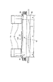
図12は、本実施の形態に係る画像形成装置の構成を説明する要部拡大図である。なお、図12において、図1及び図8と同一符号は、同一又は相当部分を示している。 FIG. 12 is an enlarged view of a main part for explaining the configuration of the image forming apparatus according to the present embodiment. In FIG. 12, the same reference numerals as those in FIGS. 1 and 8 denote the same or corresponding parts.
図12において、90は排気ファンであり、この排気ファン90は、冷却ローラ10a及び加熱ローラ5aの非通紙部に当たった後の冷却空気を回収し、同一排気口91へ排出するためのものである。なお、本実施の形態においては、既述した第1及び第2の参考例で説明した構成の冷却ファン70,76、第1ダクト71及び第2ダクト72が配置されている。
In FIG. 12,
そして、冷却ファン70,76により第1ダクト71及び第2ダクト72から冷却空気が吹き出されると、冷却空気は、まず冷却ローラ対10及び加熱ローラ5aの非通紙部に当たったはそれぞれの下流部分の外周に沿って流れる。そして、この後、矢印Y2,Z1に示すように排気ファン90により吸い込まれて同一排気口91から排気される。
When the cooling air is blown out from the
ここで、このように第1及び第2ダクト71,72から吹き出された冷却空気を同一排気口91から排気するようにすることにより、排気ファン90を個別に設けることなく、コストを削減できる。さらに、排気口の占有領域を小さくできることから、熱い排気風が排出されない領域で形成されるユーザー操作の有効スペースを増大することができる。
Here, the cooling air blown out from the first and
なお、本実施の形態では、冷却ファン70,76は第1ダクト71及び第2ダクト72にそれぞれ設けたが、一つの冷却ファンからの冷却空気を第1ダクト71及び第2ダクト72の形状により、冷却ローラ10aと加熱ローラ5aに導くようにしてもよい。
In the present embodiment, the cooling
5 定着ローラ対
5a 加熱ローラ
5b 加圧ローラ
10 冷却ローラ対
70 冷却ファン
71 第1ダクト
76 冷却ファン
72 第2ダクト
90 排気ファン
91 同一排気口
100 画像形成装置
102 画像形成部
P シート
5 Fixing
Claims (8)
前記回転体対の搬送方向下流側に設けられ、前記回転体対により搬送されるシートが通過するシート搬送路と、
前記回転体対を冷却する冷却空気を送風する送風手段と、
前記回転体対の一方の回転体の外周へ向かって延び、かつ延長線が前記回転体対のニップ中心よりも搬送方向の下流を通る斜面を有し、前記送風手段からの冷却空気を前記回転体対の一方の回転体に向けて吹き出す吹き出し部と、
前記シート搬送路からみて前記吹き出し部とは反対側に設けられ、前記吹き出し部から吹き出された冷却空気を排気する排気ファンと、を備え、
前記吹き出し部の前記斜面により、前記冷却空気の吹き出し方向が前記回転体対の一方の回転体の回転方向と逆方向となり、且つ、前記シート搬送路における、前記回転体対のニップよりも搬送方向下流側の部分の中に流れるよう前記吹き出し部から冷却空気が吹き出され、前記吹き出し部により吹き出された後、前記シート搬送路を横切るように流れた冷却空気を前記排気ファンにより排気することを特徴とする画像形成装置。 In an image forming apparatus comprising a pair of rotating bodies that convey a sheet, and cooling the pair of rotating bodies with air,
A sheet conveying path provided on the downstream side in the conveying direction of the pair of rotating bodies, through which a sheet conveyed by the pair of rotating bodies passes;
A blowing means for blowing cooling air for cooling the pair of rotating bodies;
The extending line has an inclined surface extending toward the outer periphery of one rotating body of the rotating body pair and passing downstream in the conveying direction from the center of the nip of the rotating body pair, and the cooling air from the blowing means is rotated. A blowing part that blows out toward one of the rotating bodies of the body pair;
An exhaust fan that is provided on the opposite side of the blowing portion as viewed from the sheet conveying path and exhausts the cooling air blown out from the blowing portion,
Due to the inclined surface of the blowing section, the blowing direction of the cooling air is opposite to the rotating direction of one rotating body of the rotating body pair, and the conveying direction is more than the nip of the rotating body pair in the sheet conveying path. cooling air from the blowout portion to flow into the downstream portion is blown, after being blown out by the balloon portion, characterized by evacuating the cooling air flowing across the sheet conveying path by the exhaust fan An image forming apparatus.
前記回転体対の一方の回転体は、前記定着手段のシート搬送方向下流側に配置され、シートを搬送する際、シートの熱を吸収する吸熱ローラであり、前記吹き出し部は前記吸熱ローラに向けて冷却空気を吹き出すための吸熱ローラ用ダクトであることを特徴とする請求項1又は2記載の画像形成装置。 A fixing means for fixing an unfixed image on the sheet to the sheet;
One rotating body of the pair of rotating bodies is disposed on the downstream side in the sheet conveying direction of the fixing unit, and is a heat absorbing roller that absorbs the heat of the sheet when conveying the sheet, and the blowing portion faces the heat absorbing roller. The image forming apparatus according to claim 1, wherein the image forming apparatus is a duct for a heat absorption roller for blowing out cooling air.
前記回転体対の一方の回転体は、前記加熱ローラであり、前記吹き出し部は前記加熱ローラに向けて冷却空気を吹き出すための加熱ローラ用ダクトであることを特徴とする請求項1又は2記載の画像形成装置。 A heating roller and a pressure unit that contacts the heating roller, and a fixing unit that fixes an unfixed image on the sheet to the sheet.
3. The heating roller according to claim 1, wherein one rotating body of the pair of rotating bodies is the heating roller, and the blowing portion is a heating roller duct for blowing cooling air toward the heating roller. Image forming apparatus.
前記回転体対の一方の回転体は、前記定着手段のシート搬送方向下流側に配置され、シートを搬送する際、シートの熱を吸収する吸熱ローラであり、
前記吹き出し部は前記加熱ローラに向けて冷却空気を吹き出すための加熱ローラ用ダクト及び前記吸熱ローラに向けて冷却空気を吹き出すための吸熱ローラ用ダクトであり、
前記吸熱ローラ用ダクト及び加熱ローラ用ダクトから吹き出された冷却空気を同一の排気口により排気することを特徴とする請求項1又は2記載の画像形成装置。 A heating roller and a pressure unit that contacts the heating roller, and a fixing unit that fixes an unfixed image on the sheet to the sheet.
One rotating body of the pair of rotating bodies is disposed on the downstream side in the sheet conveying direction of the fixing unit, and is an endothermic roller that absorbs the heat of the sheet when conveying the sheet,
The blowing section is a heating roller duct for blowing cooling air toward the heating roller and a heat absorbing roller duct for blowing cooling air toward the heat absorption roller,
The heat absorbing rollers duct and an image forming apparatus according to claim 1, wherein evacuating the cooling air blown from the heating roller duct by the same exhaust port.
Priority Applications (3)
| Application Number | Priority Date | Filing Date | Title |
|---|---|---|---|
| JP2005265421A JP4939018B2 (en) | 2005-09-13 | 2005-09-13 | Image forming apparatus |
| US11/530,156 US7890014B2 (en) | 2005-09-13 | 2006-09-08 | Image forming apparatus with air blowing device for cooling rotary member |
| US12/981,614 US8086131B2 (en) | 2005-09-13 | 2010-12-30 | Image forming apparatus |
Applications Claiming Priority (1)
| Application Number | Priority Date | Filing Date | Title |
|---|---|---|---|
| JP2005265421A JP4939018B2 (en) | 2005-09-13 | 2005-09-13 | Image forming apparatus |
Publications (2)
| Publication Number | Publication Date |
|---|---|
| JP2007078984A JP2007078984A (en) | 2007-03-29 |
| JP4939018B2 true JP4939018B2 (en) | 2012-05-23 |
Family
ID=37855261
Family Applications (1)
| Application Number | Title | Priority Date | Filing Date |
|---|---|---|---|
| JP2005265421A Expired - Fee Related JP4939018B2 (en) | 2005-09-13 | 2005-09-13 | Image forming apparatus |
Country Status (2)
| Country | Link |
|---|---|
| US (2) | US7890014B2 (en) |
| JP (1) | JP4939018B2 (en) |
Families Citing this family (36)
| Publication number | Priority date | Publication date | Assignee | Title |
|---|---|---|---|---|
| US7409172B2 (en) * | 2005-03-29 | 2008-08-05 | Canon Kabushiki Kaisha | Image forming apparatus |
| US7398027B2 (en) * | 2005-03-30 | 2008-07-08 | Canon Kabushiki Kaisha | Image forming apparatus with conveyance speed control based in part on loop detection |
| JP2007079033A (en) * | 2005-09-13 | 2007-03-29 | Canon Inc | Image heating apparatus |
| JP4709030B2 (en) * | 2006-02-20 | 2011-06-22 | 株式会社東芝 | Image forming apparatus |
| JP4944529B2 (en) * | 2006-07-27 | 2012-06-06 | キヤノン株式会社 | Image heating device |
| JP2008250034A (en) * | 2007-03-30 | 2008-10-16 | Kyocera Mita Corp | Image forming device |
| DE102007048158B3 (en) * | 2007-10-08 | 2009-05-20 | OCé PRINTING SYSTEMS GMBH | Cooling and cooling method for a substrate in an electrographic printer or copier |
| JP2009192623A (en) * | 2008-02-12 | 2009-08-27 | Brother Ind Ltd | Image forming apparatus |
| JP2010054578A (en) * | 2008-08-26 | 2010-03-11 | Ricoh Co Ltd | Image forming apparatus |
| JP2010054813A (en) * | 2008-08-28 | 2010-03-11 | Brother Ind Ltd | Image forming apparatus |
| JP5150522B2 (en) * | 2009-01-22 | 2013-02-20 | 京セラドキュメントソリューションズ株式会社 | Paper conveying apparatus and image forming apparatus having the same |
| US8351817B2 (en) * | 2009-08-26 | 2013-01-08 | Ricoh Company, Ltd. | Cooling device and image forming device |
| JP5537879B2 (en) * | 2009-09-28 | 2014-07-02 | 京セラドキュメントソリューションズ株式会社 | Image forming apparatus |
| JP5532891B2 (en) * | 2009-12-11 | 2014-06-25 | 富士ゼロックス株式会社 | Fixing apparatus and image forming apparatus |
| JP4741024B1 (en) * | 2010-01-27 | 2011-08-03 | シャープ株式会社 | Image forming apparatus |
| JP5035364B2 (en) * | 2010-02-22 | 2012-09-26 | ブラザー工業株式会社 | Image forming apparatus |
| JP2012048058A (en) * | 2010-08-27 | 2012-03-08 | Canon Inc | Image forming apparatus |
| JP5984238B2 (en) * | 2010-10-16 | 2016-09-06 | キヤノンファインテック株式会社 | Image forming apparatus |
| JP5772106B2 (en) * | 2011-03-17 | 2015-09-02 | 株式会社リコー | Fixing apparatus and image forming apparatus |
| JP5832134B2 (en) | 2011-05-02 | 2015-12-16 | キヤノン株式会社 | Image heating device |
| JP5858648B2 (en) * | 2011-06-03 | 2016-02-10 | キヤノン株式会社 | Image forming apparatus |
| JP5865823B2 (en) * | 2012-12-07 | 2016-02-17 | 株式会社沖データ | Image forming apparatus |
| US9429886B2 (en) | 2013-03-22 | 2016-08-30 | Canon Kabushiki Kaisha | Image forming apparatus having fixing device and blower for the fixing device |
| JP6234139B2 (en) * | 2013-09-27 | 2017-11-22 | キヤノン株式会社 | Fixing device |
| JP6492759B2 (en) * | 2015-02-25 | 2019-04-03 | 富士ゼロックス株式会社 | Heating and conveying apparatus, fixing apparatus and image forming apparatus |
| JP6485266B2 (en) * | 2015-07-17 | 2019-03-20 | 富士ゼロックス株式会社 | Image forming apparatus |
| US10175647B2 (en) | 2016-11-07 | 2019-01-08 | Kabushiki Kaisha Toshiba | Image forming apparatus comprising a control unit that controls a fan and a guide |
| JP6949556B2 (en) * | 2017-05-25 | 2021-10-13 | キヤノン株式会社 | Image forming device |
| JP7007182B2 (en) * | 2017-12-27 | 2022-01-24 | シャープ株式会社 | Image forming device |
| JP2020060676A (en) * | 2018-10-10 | 2020-04-16 | 株式会社リコー | Heater, fixing device, and image forming apparatus |
| JP7169542B2 (en) * | 2019-01-08 | 2022-11-11 | 株式会社リコー | Cooling device and image forming device |
| JP7230665B2 (en) * | 2019-04-23 | 2023-03-01 | コニカミノルタ株式会社 | Fixing device and image forming device |
| JP7267856B2 (en) * | 2019-07-01 | 2023-05-02 | キヤノン株式会社 | image forming device |
| JP2022072014A (en) * | 2020-10-29 | 2022-05-17 | コニカミノルタ株式会社 | Image forming apparatus |
| JP2023001982A (en) * | 2021-06-22 | 2023-01-10 | 京セラドキュメントソリューションズ株式会社 | Image forming apparatus |
| JP2023143462A (en) * | 2022-03-25 | 2023-10-06 | 富士フイルムビジネスイノベーション株式会社 | Image forming device |
Family Cites Families (26)
| Publication number | Priority date | Publication date | Assignee | Title |
|---|---|---|---|---|
| JPH01266558A (en) * | 1988-04-19 | 1989-10-24 | Toshiba Corp | Image forming device |
| JPH04104264A (en) * | 1990-08-24 | 1992-04-06 | Ricoh Co Ltd | Cooling device |
| JPH04256976A (en) * | 1991-02-08 | 1992-09-11 | Ricoh Co Ltd | Recording sheet cooling device for image recorder |
| JPH0561374A (en) * | 1991-08-30 | 1993-03-12 | Canon Inc | Fixing device |
| JPH05119669A (en) | 1991-10-25 | 1993-05-18 | Canon Inc | Fixing device |
| IT1256874B (en) * | 1992-02-17 | 1995-12-27 | Olivetti Canon Ind Spa | VENTILATION AND COOLING DEVICE FOR A COPIER. |
| JPH0619246A (en) | 1992-06-29 | 1994-01-28 | Canon Inc | Image forming device and heat fixing-device |
| JPH0675490A (en) * | 1992-08-26 | 1994-03-18 | Nec Corp | Fixing device for electrophotographic printer |
| JPH1074017A (en) | 1996-08-30 | 1998-03-17 | Minolta Co Ltd | Fixing device |
| JPH10133440A (en) | 1996-10-28 | 1998-05-22 | Ricoh Co Ltd | Cooling device for recording sheet |
| JPH10268735A (en) * | 1997-03-25 | 1998-10-09 | Ricoh Co Ltd | Cooling system |
| US6219497B1 (en) * | 1999-11-23 | 2001-04-17 | Xerox Corporation | Apparatus and method for reducing condensation in an image forming apparatus |
| JP2001265142A (en) * | 2000-03-23 | 2001-09-28 | Canon Inc | Thermal fixing machine |
| DE10024134A1 (en) | 2000-05-18 | 2001-11-22 | Nexpress Solutions Llc | Device for starting and stopping a feed roller of a printing machine |
| JP2002287564A (en) | 2001-03-28 | 2002-10-03 | Konica Corp | Image forming apparatus and fixing device |
| JP3576991B2 (en) | 2001-04-17 | 2004-10-13 | 株式会社沖データ | Fixing device |
| JP2003076209A (en) | 2001-08-31 | 2003-03-14 | Fuji Xerox Co Ltd | Fixing device |
| JP2003255809A (en) | 2002-03-04 | 2003-09-10 | Canon Inc | Image forming apparatus |
| JP2003330298A (en) * | 2002-05-15 | 2003-11-19 | Fuji Xerox Co Ltd | Fixing device |
| JP2004109732A (en) | 2002-09-20 | 2004-04-08 | Canon Inc | Image forming device |
| JP4172252B2 (en) | 2002-11-06 | 2008-10-29 | コニカミノルタホールディングス株式会社 | Fixing apparatus and image forming apparatus |
| JP2005315917A (en) * | 2004-04-27 | 2005-11-10 | Konica Minolta Business Technologies Inc | Image forming apparatus |
| JP4371960B2 (en) * | 2004-09-06 | 2009-11-25 | キヤノン株式会社 | Image forming apparatus |
| US7409172B2 (en) * | 2005-03-29 | 2008-08-05 | Canon Kabushiki Kaisha | Image forming apparatus |
| US7398027B2 (en) * | 2005-03-30 | 2008-07-08 | Canon Kabushiki Kaisha | Image forming apparatus with conveyance speed control based in part on loop detection |
| JP2006323154A (en) * | 2005-05-19 | 2006-11-30 | Canon Inc | Image forming apparatus |
-
2005
- 2005-09-13 JP JP2005265421A patent/JP4939018B2/en not_active Expired - Fee Related
-
2006
- 2006-09-08 US US11/530,156 patent/US7890014B2/en not_active Expired - Fee Related
-
2010
- 2010-12-30 US US12/981,614 patent/US8086131B2/en not_active Expired - Fee Related
Also Published As
| Publication number | Publication date |
|---|---|
| JP2007078984A (en) | 2007-03-29 |
| US7890014B2 (en) | 2011-02-15 |
| US20110097102A1 (en) | 2011-04-28 |
| US20070059023A1 (en) | 2007-03-15 |
| US8086131B2 (en) | 2011-12-27 |
Similar Documents
| Publication | Publication Date | Title |
|---|---|---|
| JP4939018B2 (en) | Image forming apparatus | |
| JP5006578B2 (en) | Image forming apparatus | |
| JP5100228B2 (en) | Image heating device | |
| US7352979B2 (en) | Image forming apparatus having a cooling section in a fixing apparatus | |
| JP4586867B2 (en) | Fixing apparatus and image forming apparatus | |
| JP4605482B2 (en) | Glossiness imparting device and image forming system | |
| JP2010266705A (en) | Fixing and image forming apparatus | |
| JP5322507B2 (en) | Fixing apparatus and image forming apparatus | |
| US10345745B2 (en) | Image forming apparatus and fixing device that control an air blowing device based on one of a recording material size and a size of a print region of an image | |
| JP5332180B2 (en) | Fixing apparatus and image forming apparatus | |
| JP2007199383A (en) | Fixing device and image forming apparatus | |
| JP5617376B2 (en) | Fixing apparatus and image forming apparatus | |
| JP2008298831A (en) | Fixing device and image forming apparatus | |
| JP2008014986A (en) | Image forming apparatus | |
| JP2005017762A (en) | Fixing device and image forming apparatus | |
| JP2004109732A (en) | Image forming device | |
| JP2005352193A (en) | Image forming apparatus | |
| JP5622780B2 (en) | Fixing apparatus and image forming apparatus | |
| JP5879411B2 (en) | Fixing apparatus and image forming apparatus | |
| JP2019109395A (en) | Image formation apparatus | |
| JP4384007B2 (en) | Sheet discharging apparatus and image forming apparatus | |
| JP2019128479A (en) | Fixing device and image forming apparatus | |
| JP2023001590A (en) | Air blowing device and image forming apparatus | |
| JP2022124727A (en) | Image forming apparatus | |
| JP2019095532A (en) | Fixation device |
Legal Events
| Date | Code | Title | Description |
|---|---|---|---|
| A621 | Written request for application examination |
Free format text: JAPANESE INTERMEDIATE CODE: A621 Effective date: 20080911 |
|
| A131 | Notification of reasons for refusal |
Free format text: JAPANESE INTERMEDIATE CODE: A131 Effective date: 20100921 |
|
| A521 | Request for written amendment filed |
Free format text: JAPANESE INTERMEDIATE CODE: A523 Effective date: 20101122 |
|
| A131 | Notification of reasons for refusal |
Free format text: JAPANESE INTERMEDIATE CODE: A131 Effective date: 20110517 |
|
| A521 | Request for written amendment filed |
Free format text: JAPANESE INTERMEDIATE CODE: A523 Effective date: 20110719 |
|
| RD05 | Notification of revocation of power of attorney |
Free format text: JAPANESE INTERMEDIATE CODE: A7425 Effective date: 20120125 |
|
| RD03 | Notification of appointment of power of attorney |
Free format text: JAPANESE INTERMEDIATE CODE: A7423 Effective date: 20120203 |
|
| TRDD | Decision of grant or rejection written | ||
| A01 | Written decision to grant a patent or to grant a registration (utility model) |
Free format text: JAPANESE INTERMEDIATE CODE: A01 Effective date: 20120221 |
|
| A01 | Written decision to grant a patent or to grant a registration (utility model) |
Free format text: JAPANESE INTERMEDIATE CODE: A01 |
|
| A61 | First payment of annual fees (during grant procedure) |
Free format text: JAPANESE INTERMEDIATE CODE: A61 Effective date: 20120224 |
|
| FPAY | Renewal fee payment (event date is renewal date of database) |
Free format text: PAYMENT UNTIL: 20150302 Year of fee payment: 3 |
|
| R151 | Written notification of patent or utility model registration |
Ref document number: 4939018 Country of ref document: JP Free format text: JAPANESE INTERMEDIATE CODE: R151 |
|
| FPAY | Renewal fee payment (event date is renewal date of database) |
Free format text: PAYMENT UNTIL: 20150302 Year of fee payment: 3 |
|
| LAPS | Cancellation because of no payment of annual fees |