JP4926757B2 - Imaging apparatus and control method - Google Patents
Imaging apparatus and control method Download PDFInfo
- Publication number
- JP4926757B2 JP4926757B2 JP2007046297A JP2007046297A JP4926757B2 JP 4926757 B2 JP4926757 B2 JP 4926757B2 JP 2007046297 A JP2007046297 A JP 2007046297A JP 2007046297 A JP2007046297 A JP 2007046297A JP 4926757 B2 JP4926757 B2 JP 4926757B2
- Authority
- JP
- Japan
- Prior art keywords
- image
- detected
- image signal
- face
- reliability
- Prior art date
- Legal status (The legal status is an assumption and is not a legal conclusion. Google has not performed a legal analysis and makes no representation as to the accuracy of the status listed.)
- Expired - Fee Related
Links
Images


Description
本発明は、撮像装置及び制御方法に関し、更に詳しくは、撮像して得た画像から任意の対象物の画像領域を検出可能な撮像装置及び制御方法にする。 The present invention relates to an imaging apparatus and a control method, and more specifically, to an imaging apparatus and a control method capable of detecting an image area of an arbitrary object from an image obtained by imaging.
従来、画像データから所定の条件を満たす対象を繰り返し検出する機能を有する装置がある。そのような装置の一例として、光電変換素子である固体撮像素子にて画像データを得る撮像装置において次のような装置が提案されている。先ず、得られた画像データの中から形状解析等の手法によって所定の対象物(主被写体)を自動的に検出する。そして、主被写体が検出されると画面でその旨を表示すると共に、検出された主被写体に対して焦点検出エリアを表示し、この焦点検出エリアに対して焦点調節動作を行わせる(例えば、特許文献1を参照)。この撮像装置によれば、画像データ全体から対象物の検出を行うことで、対象物が被写界のどこに存在しようとも、対象物に対して焦点調節動作を行うことができる。 Conventionally, there is an apparatus having a function of repeatedly detecting an object satisfying a predetermined condition from image data. As an example of such an apparatus, the following apparatus has been proposed as an image pickup apparatus that obtains image data with a solid-state image pickup element that is a photoelectric conversion element. First, a predetermined target (main subject) is automatically detected from the obtained image data by a technique such as shape analysis. When a main subject is detected, the fact is displayed on the screen, and a focus detection area is displayed for the detected main subject, and a focus adjustment operation is performed on the focus detection area (for example, patents). Reference 1). According to this imaging apparatus, by performing detection of an object from the entire image data, it is possible to perform a focus adjustment operation on the object regardless of where the object exists in the object scene.
また、検出した対象物を追尾するためには、形状解析等の手法による対象物の検出動作を周期的に行う必要がある。そこで、撮像装置の電子ビューファインダ(以下、EVFという)等の表示装置にて、被写体の動きを観察するために画像データを連続的に表示する場合は、対象物の動きに合わせて対象物の検出結果も更新することが望まれる。そこで、周期的に行われる対象物の検出結果を随時更新し、最新の対象物の検出結果を常に表示する処理が行われる。例えば、対象物が検出された場合には、その検出された領域に、検出されたことを示す枠を被写体の画像に重畳させて表示する。 In addition, in order to track the detected object, it is necessary to periodically perform an object detection operation using a technique such as shape analysis. Therefore, when image data is continuously displayed on a display device such as an electronic viewfinder (hereinafter referred to as EVF) of the image pickup device in order to observe the movement of the subject, the object is moved in accordance with the movement of the target. It is desirable to update the detection result. In view of this, a process of periodically updating the detection result of the target object is performed as needed, and the latest detection result of the target object is always displayed. For example, when an object is detected, a frame indicating that the object is detected is superimposed on the detected area and displayed.
しかしながら、電子ズームにより対象物を含むライブ画像の一部が拡大され、低解像度での表示がなされ、高確率で対象物を検出することが困難な場合に、特許文献1のような技術では以下のような問題が想定される。即ち、EVF上でユーザが対象物を認識できるにも関わらず、対象物が検出されず、また検出されたことを示す枠も重畳表示されず、かつ対象物に対して焦点調節動作が行なわれない可能性がある。 However, when a part of a live image including an object is enlarged by electronic zoom, a display with a low resolution is performed, and it is difficult to detect the object with high probability, a technique such as Patent Document 1 is described below. The following problems are assumed. That is, although the user can recognize the object on the EVF, the object is not detected, the frame indicating that the object is detected is not superimposed, and the focus adjustment operation is performed on the object. There is no possibility.
本発明の撮像装置は、被写体光学像を電気的な画像信号に変換して順次出力する撮像手段と、前記撮像手段の出力から生成された第1の画像信号の一部を、信号補間により拡大して、第2の画像信号を生成する電子ズーム手段と、前記第1の画像信号より表される画像、及び、前記第2の画像信号により表される画像から、顔を表す画像領域を検出すると共に、当該検出した画像領域が顔を表している確からしさを表す信頼度と当該検出した画像領域の位置とを含む情報を検出する検出手段と、前記検出手段により検出された前記信頼度を、閾値と比較する比較手段と、前記比較手段により比較した結果、前記検出された信頼度が前記閾値よりも高い場合に、前記情報を記憶する記憶手段とを有し、前記第2の画像信号により表される画像から検出された画像領域に対する前記閾値を、前記第1の画像信号により表される画像から検出された画像領域に対する前記閾値よりも低くしたことを特徴とする。 An imaging apparatus according to the present invention includes an imaging unit that converts a subject optical image into an electrical image signal and sequentially outputs it, and enlarges a part of the first image signal generated from the output of the imaging unit by signal interpolation. And detecting an image region representing the face from the electronic zoom means for generating the second image signal, the image represented by the first image signal, and the image represented by the second image signal. And detecting means for detecting information including the reliability indicating the likelihood that the detected image area represents a face and the position of the detected image area, and the reliability detected by the detecting means. A comparison means for comparing with a threshold value; and a storage means for storing the information when the detected reliability is higher than the threshold value as a result of comparison by the comparison means, and the second image signal. The image represented by The threshold for the detected image area, characterized by being lower than the threshold for the detected image area from an image represented by the first image signal.
また、本発明の撮像装置の制御方法は、撮像手段が、被写体光学像を電気的な画像信号に変換して順次出力する撮像工程と、電子ズーム手段が、前記撮像工程の出力から生成された第1の画像信号の一部を、信号補間により拡大して、第2の画像信号を生成する電子ズーム工程と、検出手段が、前記第1の画像信号より表される画像、及び、前記第2の画像信号により表される画像から、顔を表す画像領域を検出すると共に、当該検出した画像領域が顔を表している確からしさを表す信頼度と当該検出した画像領域の位置とを含む情報を検出する検出工程と、比較手段が、前記検出工程で検出された前記信頼度を、閾値と比較する比較工程と、記憶手段が、前記比較工程において比較した結果、前記検出された信頼度が前記閾値よりも高い場合に、前記情報を記憶する記憶工程とを有し、前記第2の画像信号により表される画像から検出された画像領域に対する前記閾値を、前記第1の画像信号により表される画像から検出された画像領域に対する前記閾値よりも低くしたことを特徴とする。
In addition, according to the control method of the imaging apparatus of the present invention, the imaging unit converts the subject optical image into an electrical image signal and sequentially outputs the imaging step, and the electronic zoom unit is generated from the output of the imaging step. An electronic zoom process of generating a second image signal by enlarging a part of the first image signal by signal interpolation, an image represented by the first image signal, and the first Information including an image area representing a face from the image represented by the
本発明によれば、画像の解像度が高い場合の対象物の検出精度を保ちながら、電子ズームにより画像の解像度が低くなっても、対象物の検出を行うことが可能となる。 According to the present invention, it is possible to detect an object even when the resolution of the image is lowered by electronic zoom while maintaining the detection accuracy of the object when the resolution of the image is high.
以下、添付図面を参照して本発明を実施するための最良の形態を詳細に説明する。 The best mode for carrying out the present invention will be described below in detail with reference to the accompanying drawings.
本実施の形態における撮像装置1の概略構成について、図1を参照して説明する。 A schematic configuration of the imaging apparatus 1 in the present embodiment will be described with reference to FIG.
101は、光学ズーム手段の一例であるズームレンズ、フォーカスレンズ等を含む撮影レンズ、102は絞り機能を備えたシャッターである。103は、撮像手段の一例として被写体光学像を電気的な画像信号に変換するCCDやCMOSセンサに代表される撮像素子、104は撮像素子103から出力されるアナログ出力をデジタル信号(デジタル画像データ)に変換するA/D変換器である。
105は撮像素子103、A/D変換器104、D/A変換器110にクロック信号や制御信号を供給するタイミング発生回路であり、メモリ制御回路109およびシステム制御部107により制御される。
A
106は画像処理回路であり、A/D変換器104からの画像データ或いはメモリ制御回路109からの画像データに対して所定の画素補間処理や色変換処理を行う。また、画像処理回路106は顔検出部126を含み、画像データから顔の検出及び検出した顔の情報の取得を行う。なお、顔検出部126は検出手段の一例であり、人の顔を検出の対象物とした場合の構成である。
An
顔の検出技術としては、例えば、ニューラルネットワークに代表される学習を用いる方法や、目や鼻といった物理的な形状の特徴のある部位を画像領域からテンプレートマッチングにより検出する手法がある。他にも、肌の色や目の形といった画像特徴量を検出し、統計的解析を用いる手法が挙げられる(例えば、特開平10−232934号公報や特開2000−48184号公報等を参照)。 As a face detection technique, for example, there are a method using learning typified by a neural network, and a method of detecting a part having physical shape features such as eyes and nose from an image region by template matching. In addition, there is a method of detecting image feature quantities such as skin color and eye shape and using statistical analysis (see, for example, Japanese Patent Laid-Open Nos. 10-232934 and 2000-48184). .
本実施の形態では、一対の目(両目)、鼻、口を検出し、これらの相対位置より人物の顔を示す画像領域(以下、「顔領域」と呼ぶ。)を決定する方法により顔検出処理を行うものとして説明する。この方法では、検出の対象となる人物が片目を閉じていたり、不意に余所見をして横向きになった場合には、基準となる一対の目が存在しないために顔領域の検出ができなくなる。また、顔の情報とは、顔の有無、検出された場合の顔としての確からしさの指標である信頼度、顔の位置、サイズ等が含まれる。図2は、この検出方法における信頼度の基準の一例を示す。図2では、信頼度の数字が少ない方が、より信頼度が高いことを示している。なお、信頼度の基準は図2に示す例に限られるものではないことは言うまでもない。 In the present embodiment, a face is detected by a method of detecting a pair of eyes (both eyes), nose, and mouth and determining an image area (hereinafter referred to as a “face area”) showing a person's face from these relative positions. It demonstrates as what performs a process. In this method, when a person to be detected closes one eye or unexpectedly looks sideways, the face area cannot be detected because there is no pair of eyes serving as a reference. The face information includes the presence / absence of a face, reliability indicating the likelihood of the face when it is detected, face position, size, and the like. FIG. 2 shows an example of the criterion of reliability in this detection method. FIG. 2 shows that the smaller the reliability number, the higher the reliability. Needless to say, the criterion of reliability is not limited to the example shown in FIG.
更に、画像処理回路106は、電子ズーム手段の一例として電子ズーム部136を含む。電子ズーム部136は、操作部113を介して撮影者からズームレンズによるズーム倍率の限界を超えてズーム倍率を高くする指示があった場合に、指示されたズーム倍率に応じて画像信号の一部を信号補間して拡大する。
Furthermore, the
また、画像処理回路106においては、撮像した画像データを用いて所定の演算処理を行う。そして、得られた演算結果に基づいてシステム制御部107が、合焦制御としてAF(オートフォーカス)処理、及び、露出制御としてAE(自動露出)処理、EF(フラッシュプリ発光)処理を行う。更に、AWB(オートホワイトバランス)処理も行う。
Further, the
A/D変換器104から出力されたデジタル画像データが、画像処理回路106及びメモリ制御回路109を介して、或いはA/D変換器104から直接メモリ制御回路109を介して、画像メモリ108、あるいは画像表示メモリ111に書き込まれる。
The digital image data output from the A /
108は撮影した静止画像や動画像を格納するための画像メモリであり、所定枚数の静止画像や所定時間の動画像を格納するのに十分な記憶容量を備えている。これにより、複数枚の静止画像を連続して撮影する連射撮影やパノラマ撮影の場合にも、高速かつ大量の画像書き込みをメモリ108に対して行うことが可能となる。また、メモリ108はシステム制御部107の作業領域としても使用することが可能である。
111は画像表示メモリであり、画像表示メモリ111に書き込まれた表示用の画像データはD/A変換器110を介して表示部112に表示される。表示部112は、システム制御部107の指示により任意に表示をON/OFFすることが可能であり、表示をOFFにした場合には撮像装置1の電力消費を大幅に低減することができる。
113は、シャッターボタンに代表される各種スイッチ、モードダイヤルやスライダ等の操作部材、ズーム倍率を指示するための操作部材、表示部112を利用したソフトスイッチなどを含む操作部である。操作部113を用いて入力されたユーザーの指示がシステム制御部107に送られる。なお、本実施の形態ではシャッターボタンは公知の2段式のシャッターボタンとし、シャッターボタンの第1ストローク(例えば半押し)によりシャッタースイッチSW1がONとなり、AF処理、AE処理、AWB処理、EF処理等の動作開始が指示される。また、シャッターボタンの第2ストローク(例えば全押し)によりシャッタースイッチSW2がONとなり、露光処理、現像処理、及び記録処理からなる一連の処理の動作開始が指示される。また、操作部113により、撮像された画像から顔の検出を行う顔検出モードを設定することができる。
An
<第1の実施形態>
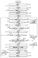
次に、本願発明の第1の実施形態における上記構成を有する撮像装置1の撮像モード時の動作について、図3のフローチャートを参照して説明する。
<First Embodiment>
Next, the operation in the imaging mode of the imaging apparatus 1 having the above-described configuration according to the first embodiment of the present invention will be described with reference to the flowchart of FIG.
ステップS101において電池投入により電源を入れた後、システム制御部107は撮像装置1が動作可能な各種モードの内、設定されているモードを確認し(ステップS102)、撮像モードが設定されているかどうかを判断する(ステップS103)。撮像モード以外のモードでは以下に説明する処理は行わないので、本第1の実施形態ではステップS102に戻って設定されているモードの確認及び撮像モードが設定されたかどうかの判断を繰り返す。
After turning on the battery by turning on the battery in step S101, the
撮像モードが設定されると、表示部112がOFFであればONにし(ステップS104)、ライブ画像の表示(EVF表示)を開始する(ステップS105)。なお、ライブ画像の表示は、所定周期でフレーム画像を撮像素子103から読み込み、順次表示部112に表示することにより行われる。
When the imaging mode is set, if the
次に、システム制御部107は操作部113により顔検出モードが設定されているか否かを判別する(ステップS106)。顔検出モードが設定されている場合、顔検出部126は、ライブ画像の表示用に所定周期で撮影されたフレーム画像に顔が存在するか否かを定期的に調べる(ステップS107)。顔検出は、ライブ画像用に撮影された全てのフレーム画像に対して行う必要は無く、任意に設定された周期で行う。そして、フレーム画像を調べる度に、顔の有無も含め、顔が検出された場合には検出された顔に関する情報を出力し、記憶し、随時更新する(ステップS108)。
Next, the
フレーム画像内に顔が検出された場合、顔領域を枠で表示させることができるが、本第1の実施形態では、検出された顔領域の枠を表示する条件が設定されている。その条件とは、ステップS108で取得した顔の情報(顔の有無、信頼度、位置、サイズ等)の内の所定の値が予め設定された閾値内に包含されていることである。ここで、顔領域を枠で表示させる条件の一例について説明する。 When a face is detected in the frame image, the face area can be displayed as a frame, but in the first embodiment, a condition for displaying the frame of the detected face area is set. The condition is that a predetermined value in the face information (face presence / absence, reliability, position, size, etc.) acquired in step S108 is included within a preset threshold value. Here, an example of conditions for displaying the face area with a frame will be described.
顔検出時に出力される信頼度は、ズームレンズによる光学ズーム時と電子ズーム部136による電子ズーム時とではかなり異なる。これは、電子ズーム時は光学ズーム時に比べ解像度が低くなる関係で高い信頼度での顔検出が困難であるためで、いかなるズーム倍率でも顔領域を枠で表示させる条件を一律にしてしまうと、以下のようなことが起こる。 The reliability output at the time of face detection is considerably different between the optical zoom using the zoom lens and the electronic zoom using the electronic zoom unit 136. This is because it is difficult to detect a face with high reliability because the resolution is lower than that during optical zoom during electronic zoom, and if the condition for displaying the face area in a frame is uniform at any zoom magnification, The following happens:
例えば、電子ズーム時を基準とした低い信頼度でも顔領域を枠で表示させるように設定した場合、高解像度でライブ画像が表示される光学ズーム時に、顔領域の枠表示条件を満たす低信頼度の領域が顔ではないという状況が起こり得る。逆に、光学ズーム時を基準とした高い信頼度をもって顔領域が検出された場合にのみ顔領域の枠表示を実行するように設定すると、電子ズーム時にはほとんど顔領域の枠が表示されなくなる。例えば、図5(a)に示すような顔検出結果が得られた場合、図5(b)に示すように光学ズーム時には高信頼度(信頼度1)の顔領域の回りに枠が表示されるが、低信頼度(信頼度8)の顔領域の回りには枠が表示されない。更に低信頼度(信頼度8)の顔領域を中心に電子ズームを行った場合、図5(c)に示すように、低信頼度(信頼度8)の顔領域の回りには枠が表示されない。 For example, if the face area is set to be displayed in a frame even with low reliability based on the electronic zoom, the low reliability that satisfies the frame display condition of the face area during optical zoom when a live image is displayed at high resolution A situation can occur where the region is not a face. Conversely, if the face area frame display is set to be executed only when the face area is detected with high reliability based on the optical zoom, the face area frame is hardly displayed during the electronic zoom. For example, when a face detection result as shown in FIG. 5A is obtained, a frame is displayed around a highly reliable (reliability 1) face area during optical zooming as shown in FIG. 5B. However, no frame is displayed around the face area with low reliability (reliability 8). Further, when electronic zoom is performed around a face area with low reliability (reliability 8), a frame is displayed around the face area with low reliability (reliability 8), as shown in FIG. 5C. Not.
そこで、本第1の実施形態では、ズーム倍率に応じて、顔領域の枠表示条件を異なるものとし、ズーム倍率が高い場合ほど低い信頼度であっても検出された顔領域の枠表示を実行するようにする。なお、ズームレンズによる光学ズームと電子ズーム部136による電子ズームとでは光学ズームを優先するものとする。例えばズーム倍率を上げる場合には、先ず光学ズームによるズームを行い、光学ズームで指定されたズーム倍率を達成できない場合に、電子ズームによるズームに移行する。この条件設定の一例を図4に示すが、本発明はこれに限られるものではない。 Therefore, in the first embodiment, the frame display condition of the face area is different depending on the zoom magnification, and the frame display of the detected face area is executed even when the zoom magnification is high and the reliability is low. To do. Note that the optical zoom is given priority in the optical zoom using the zoom lens and the electronic zoom using the electronic zoom unit 136. For example, when the zoom magnification is increased, first, zooming using the optical zoom is performed. If the zoom magnification specified by the optical zoom cannot be achieved, the zooming is performed using the electronic zoom. An example of this condition setting is shown in FIG. 4, but the present invention is not limited to this.
このようにズーム倍率に応じて顔領域の枠表示条件を変えることにより、適した顔領域の枠表示を行うことが可能となる。例えば、図6(a)に示すように低信頼度(信頼度8)の顔領域を中心に電子ズームを行った場合、電子ズーム倍率が所定倍率(図4では5倍)を超えていれば、図6(c)に示すように、信頼度が低くても、図6(c)のように、顔領域の枠が表示される。電子ズームにより被写体を拡大する場合には、撮影者は撮影対象の被写体を拡大することを目的としていると考えられ、顔検出モードに設定されている状況において、拡大された画像内に被写体である顔が存在している可能性は高い。従って、電子ズームによるズーム倍率が高い場合に枠表示条件として信頼度を低くすることにより、より適した枠表示を行うことが可能となる。 As described above, by changing the frame display condition of the face area according to the zoom magnification, it is possible to display a frame display of a suitable face area. For example, as shown in FIG. 6A, when electronic zoom is performed around a face area with low reliability (reliability 8), if the electronic zoom magnification exceeds a predetermined magnification (5 times in FIG. 4). As shown in FIG. 6C, even if the reliability is low, the frame of the face area is displayed as shown in FIG. 6C. When enlarging a subject by electronic zoom, it is considered that the photographer intends to enlarge the subject to be photographed, and the subject is in the enlarged image in the situation where the face detection mode is set. The possibility that a face exists is high. Therefore, it is possible to perform more suitable frame display by reducing the reliability as the frame display condition when the zoom magnification by the electronic zoom is high.
図3の動作シーケンスに戻り、画像処理回路106は、ステップS108で取得した信頼度及び現在のズーム倍率から、ステップS109で図4に示す枠表示条件を満たしているかどうかを、信頼度と枠表示条件との比較により判断する。図4に示すように、枠表示条件は光学ズーム及び電子ズームの倍率によって異なる信頼度の閾値(それぞれ、第2の信頼度及び第1の信頼度)を示しており、画像処理回路106はここでは比較手段としての役割も果たす。条件を満たしている(即ち、信頼度が枠表示条件として規定された信頼度よりも高い)場合には、ライブ画像が表示されているEVF上に、検出された顔領域を示す枠を重畳表示する(ステップS110)と共に、顔が検出された旨を表示する。更に、枠表示を行った顔領域の情報は、撮像装置1内の不図示の記憶手段に記憶、更新される。
Returning to the operation sequence of FIG. 3, the
一方、ステップS109で図4に示す枠表示条件を満たしていない(即ち、信頼度が枠表示条件として規定された信頼度よりも低い)と判断されると枠の表示は行わず、そのままステップS111に進む。 On the other hand, if it is determined in step S109 that the frame display condition shown in FIG. 4 is not satisfied (that is, the reliability is lower than the reliability defined as the frame display condition), the frame is not displayed and step S111 is performed as it is. Proceed to
また、ステップS107において顔が存在しないと判断された場合には、上述したステップS107からS110の処理は行わずに、ステップS111に直接進む。 If it is determined in step S107 that no face exists, the process directly proceeds to step S111 without performing the above-described steps S107 to S110.
ステップS111では、シャッタースイッチSW1が押下されたかどうかを判断する。押下されていなければステップS106に戻り、顔検出モードが設定されていれば、ライブ画像用に所定周期で新たに読み込まれたフレーム画像に対して上述した処理を実行する。 In step S111, it is determined whether or not the shutter switch SW1 has been pressed. If not pressed, the process returns to step S106, and if the face detection mode is set, the above-described processing is performed on the frame image newly read at a predetermined cycle for the live image.
シャッタースイッチSW1が押下されると(ステップS111でYES)、随時更新されてきた顔領域の情報の内、最新のものを用いて顔領域を示す枠を表示するか否かを判別する(ステップS112)。図4に示す枠表示条件を満たしていない場合は、撮像素子103から読み取った全画素の画像信号を用いたAF処理、TTL方式のAE処理、EF処理を実行する(ステップS114)。
When the shutter switch SW1 is pressed (YES in step S111), it is determined whether or not to display a frame indicating the face area using the latest information of the face area updated as needed (step S112). ). If the frame display conditions shown in FIG. 4 are not satisfied, AF processing, TTL AE processing, and EF processing using image signals of all pixels read from the
一方、枠表示条件を満たしている場合は、ライブ画像上(EVF表示中)に顔領域を示す枠を表示する(ステップS113)。そして、枠表示された顔領域に焦点を合わせるAF処理及び、顔領域をもとに絞り値及びシャッター速度を決定するTTL方式のAE処理、EF処理を実行する(ステップS115)。 On the other hand, when the frame display condition is satisfied, a frame indicating the face area is displayed on the live image (while EVF is being displayed) (step S113). Then, AF processing for focusing on the face area displayed in the frame and TTL AE processing and EF processing for determining the aperture value and the shutter speed based on the face area are executed (step S115).
ステップS114またはS115におけるAF、AE処理後、シャッタースイッチSW2が押下されたか否か判別する(ステップS116)。押下されていない場合は再びシャッタースイッチSW1が押下された状態か否かを判別する(ステップS119)。押下されていない場合はステップS106に戻って、上述した一連の動作を繰り返す。シャッタースイッチSW2が押下された場合は、撮像素子103が光学像を電気的な画像信号に変換し、後段の各構成により上述した処理が実行され(ステップS117)、画像が生成されて出力される(ステップS118)。その後、ステップS106に戻る。
After the AF or AE process in step S114 or S115, it is determined whether or not the shutter switch SW2 has been pressed (step S116). If not pressed, it is determined again whether or not the shutter switch SW1 is pressed (step S119). If not, the process returns to step S106 to repeat the series of operations described above. When the shutter switch SW2 is pressed, the
なお、ステップS106にて顔検出モードが設定されていない場合は、顔の検出を行わずに、ライブ画像の表示を行い(ステップS120)、ユーザがシャッタースイッチSW1を押下していなければ(ステップS121でNO)ステップS106に戻る。ユーザがシャッタースイッチSW1を押下すると(ステップS121でYES)、撮像素子103から画像信号を読み出し、読み出した全画素の画像信号を用いて、AF処理、TTL方式のAE処理、EF処理を実行する(ステップS114)。その後、上述したステップS116へ進む。
If the face detection mode is not set in step S106, the live image is displayed without detecting the face (step S120), and the user does not press the shutter switch SW1 (step S121). NO) returns to step S106. When the user presses the shutter switch SW1 (YES in step S121), an image signal is read from the
なお、上記説明では、枠表示条件に基づいて、検出した顔領域を示す枠を表示するかどうかを判断すると共に、枠表示した顔領域をAF処理、AE処理等の処理に用いるかどうかについて説明した。即ち、ここで言う枠表示条件は、検出した顔領域が実際に顔であるかどうかを判定するための基準を示すものである。従って、本第1の実施形態の特徴は検出した顔領域の枠を表示するか否かというよりも、むしろ、検出した顔領域を、その後の処理において顔として扱うかどうかを、ズーム倍率と信頼度に応じて判断するところにある。 In the above description, it is determined whether to display a frame indicating the detected face area based on the frame display condition, and whether to use the frame-displayed face area for processing such as AF processing and AE processing. did. That is, the frame display condition referred to here indicates a reference for determining whether or not the detected face area is actually a face. Therefore, the feature of the first embodiment is that whether or not the detected face area is treated as a face in the subsequent processing, rather than whether or not the frame of the detected face area is displayed. There is a place to judge according to the degree.
上記の通り本第1の実施形態によれば、ズーム倍率と検出された顔領域の信頼度とから、検出された顔領域をその後の処理に用いるか否かをより的確に判断することが可能となる。 As described above, according to the first embodiment, it is possible to more accurately determine whether or not to use the detected face area for subsequent processing from the zoom magnification and the reliability of the detected face area. It becomes.
また、枠表示条件を満たす顔領域に枠を表示することにより、撮影者は顔領域の検出の有無が一目で分かるため、顔領域に適したAF処理やAE処理等が行われる、または行われたか否かを知ることが可能となる。 Also, by displaying a frame in the face area that satisfies the frame display condition, the photographer can know at a glance whether or not the face area has been detected. Therefore, AF processing or AE processing suitable for the face area is performed or is performed. It becomes possible to know whether or not.
<第2の実施形態>
次に、本発明の第2の実施形態おける撮像装置1の撮像時の動作について、図7のフローチャートを参照して説明する。なお、図7において、図3と同様の処理には同じ参照番号を付して説明を省略し、第1の実施形態と異なる部分について主に説明を行う。
<Second Embodiment>
Next, the operation at the time of imaging of the imaging apparatus 1 in the second embodiment of the present invention will be described with reference to the flowchart of FIG. In FIG. 7, the same processes as those in FIG. 3 are denoted by the same reference numerals, and the description thereof is omitted. The description will mainly focus on the differences from the first embodiment.
ステップS211おいて電子ズームがオンの状態になるまで、ステップS111を介して第1の実施形態で上述したステップS106〜S110の処理を繰り返す。ここでは先ず、参照する枠表示条件の初期条件として、第1の実施形態で説明した図4に示すものとする。そして、撮影者の操作部113によりズーム倍率が変更され、光学ズームから電子ズームに移行する倍率になったかどうかを判定する(ステップS211)。移行する場合には(電子ズームON)、電子ズームがオンになる直前に光学ズームによるズーム倍率で得られたフレーム画像で顔が検出されたか否かを、顔の検出結果を随時記憶した記憶手段から判別する(ステップS212)。
Until the electronic zoom is turned on in step S211, the processes in steps S106 to S110 described above in the first embodiment are repeated via step S111. Here, first, as an initial condition of the frame display condition to be referred to, it is assumed to be shown in FIG. 4 described in the first embodiment. Then, it is determined whether or not the zoom magnification has been changed by the photographer's
顔の存在が確認された場合にはステップS213に進んで、枠検出条件として図4に示す条件を設定する。一方、確認されなかった場合はステップS214に進み、例えば、図8に示す枠検出条件を設定する。 If the presence of the face is confirmed, the process proceeds to step S213, and the condition shown in FIG. 4 is set as the frame detection condition. On the other hand, if not confirmed, the process proceeds to step S214, and for example, the frame detection condition shown in FIG. 8 is set.
上述した第1の実施形態では、ズーム倍率が高くなるにつれ、顔としての確からしさの指標である信頼度がより低い場合でもライブ画像上(EVF表示中)に顔領域を示す枠を表示することを説明した。しかし、この方法では、電子ズーム領域であって、かつフレーム画像内に顔が存在しない場合に、顔でないものを顔として判断し、枠表示をしてしまう可能性がある。 In the first embodiment described above, as the zoom magnification increases, a frame indicating the face area is displayed on the live image (during EVF display) even when the reliability, which is an index of the likelihood of the face, is lower. Explained. However, according to this method, when there is no face in the frame image in the electronic zoom area, a non-face may be determined as a face and a frame may be displayed.
そこで、本第2の実施形態では、電子ズームがオンになる直前のフレーム画像内に顔が存在していないことが顔の検出結果から確認された場合、顔領域の枠表示条件をズーム倍率に関わらず、例えば図8に示すように一律にする。このとき、光学ズーム時、電子ズーム時とも顔としての確からしさの指標である信頼度がかなり高い場合にのみ、ライブ画像上(EVF表示中)に顔領域の枠を表示する。 Therefore, in the second embodiment, when it is confirmed from the face detection result that the face does not exist in the frame image immediately before the electronic zoom is turned on, the frame display condition of the face area is set to the zoom magnification. Regardless, for example, as shown in FIG. At this time, the frame of the face area is displayed on the live image (during EVF display) only when the reliability, which is an index of the likelihood of the face, is high at both optical zoom and electronic zoom.
顔領域の枠表示条件の切り替え後は、ステップS111を介して、ステップS106に戻り、参照する枠表示条件が異なる(図4か図8か)以外は、上述した処理を繰り返す。 After switching the face area frame display conditions, the process returns to step S106 via step S111, and the above-described processing is repeated except that the frame display conditions to be referred to are different (FIG. 4 or FIG. 8).
上記の通り本第2の実施形態によれば、電子ズームがオンになった時にフレーム画像に顔領域が存在しない可能性が高い場合に、枠表示条件を甘くしたために起こる顔領域の誤判断を削減することが可能となる。更に、検出された顔領域の信頼度が十分に高い場合には、顔領域として判定することができるため、顔領域の判断をより適切に行うことが可能となる。 As described above, according to the second embodiment, when there is a high possibility that the face area does not exist in the frame image when the electronic zoom is turned on, an erroneous determination of the face area caused by loosening the frame display condition is performed. It becomes possible to reduce. Furthermore, when the reliability of the detected face area is sufficiently high, it can be determined as a face area, and thus the face area can be determined more appropriately.
1 撮像装置
101 撮影レンズ
102 シャッター
103 撮像素子
104 A/D変換器
105 タイミング発生回路
106 画像処理回路
107 システム制御部
108 画像メモリ
109 メモリ制御回路
110 D/A変換器
111 メモリ
112 表示部
113 操作部
126 顔検出部
136 電子ズーム部
DESCRIPTION OF SYMBOLS 1
Claims (6)
前記撮像手段の出力から生成された第1の画像信号の一部を、信号補間により拡大して、第2の画像信号を生成する電子ズーム手段と、
前記第1の画像信号より表される画像、及び、前記第2の画像信号により表される画像から、顔を表す画像領域を検出すると共に、当該検出した画像領域が顔を表している確からしさを表す信頼度と当該検出した画像領域の位置とを含む情報を検出する検出手段と、
前記検出手段により検出された前記信頼度を、閾値と比較する比較手段と、
前記比較手段により比較した結果、前記検出された信頼度が前記閾値よりも高い場合に、前記情報を記憶する記憶手段とを有し、
前記第2の画像信号により表される画像から検出された画像領域に対する前記閾値を、前記第1の画像信号により表される画像から検出された画像領域に対する前記閾値よりも低くしたことを特徴とする撮像装置。 Imaging means for converting a subject optical image into an electrical image signal and sequentially outputting it,
Electronic zoom means for enlarging a part of the first image signal generated from the output of the imaging means by signal interpolation to generate a second image signal;
An image area representing a face is detected from the image represented by the first image signal and the image represented by the second image signal, and the detected image area is likely to represent a face. Detecting means for detecting information including the reliability representing the position of the detected image region, and
Comparing means for comparing the reliability detected by the detecting means with a threshold;
A storage means for storing the information when the detected reliability is higher than the threshold as a result of comparison by the comparison means;
The threshold for the image area detected from the image represented by the second image signal is set lower than the threshold for the image area detected from the image represented by the first image signal. An imaging device.
前記検出手段は、前記第3の画像信号により表される画像から、顔を表す画像領域を検出すると共に、当該検出した画像領域が顔を表している確からしさを表す信頼度と当該検出した画像領域の位置とを含む情報を検出し、
前記第3の画像信号により表される画像から検出された画像領域に対する前記閾値を、前記第2の画像信号により表される画像から検出された画像領域に対する前記閾値よりも低くしたことを特徴とする請求項1に記載の撮像装置。 The electronic zoom means expands a part of the first image signal by signal interpolation to generate a third image signal that is larger than the second image signal,
The detection means detects an image area representing a face from an image represented by the third image signal, and also represents a reliability indicating the probability that the detected image area represents a face and the detected image. Detect information including the location of the region ,
The threshold value for the image area detected from the image represented by the third image signal is set lower than the threshold value for the image area detected from the image represented by the second image signal. The imaging device according to claim 1.
前記光学ズーム手段から前記電子ズーム手段にズーム倍率の制御を移行する場合に、前記移行した後に用いる前記閾値を決定する決定手段を更に有し、
前記決定手段は、前記移行の直前に前記検出手段により顔を表す画像領域が検出できなかった場合に、前記移行した後の閾値を、前記第1の画像信号により表される画像から検出された画像領域に対する前記閾値と同じ閾値に決定することを特徴とする請求項1乃至3のいずれか1項に記載の撮像装置。 Further comprising optical zoom means comprising a zoom lens;
In the case of shifting the zoom magnification control from the optical zoom unit to the electronic zoom unit, the apparatus further includes a determination unit that determines the threshold value used after the shift.
Said determining means, when the image area representing the face by the previous SL detecting means immediately before the transition can not be detected, the threshold value after the transition is detected from the image represented by the first image signal The imaging apparatus according to claim 1, wherein the imaging apparatus determines a threshold value that is the same as the threshold value for the image area.
電子ズーム手段が、前記撮像工程の出力から生成された第1の画像信号の一部を、信号補間により拡大して、第2の画像信号を生成する電子ズーム工程と、
検出手段が、前記第1の画像信号より表される画像、及び、前記第2の画像信号により表される画像から、顔を表す画像領域を検出すると共に、当該検出した画像領域が顔を表している確からしさを表す信頼度と当該検出した画像領域の位置とを含む情報を検出する検出工程と、
比較手段が、前記検出工程で検出された前記信頼度を、閾値と比較する比較工程と、
記憶手段が、前記比較工程において比較した結果、前記検出された信頼度が前記閾値よりも高い場合に、前記情報を記憶する記憶工程とを有し、
前記第2の画像信号により表される画像から検出された画像領域に対する前記閾値を、前記第1の画像信号により表される画像から検出された画像領域に対する前記閾値よりも低くしたことを特徴とする撮像装置の制御方法。 An imaging step in which the imaging means converts the subject optical image into an electrical image signal and sequentially outputs the electrical signal;
An electronic zoom step in which an electronic zoom means generates a second image signal by enlarging a part of the first image signal generated from the output of the imaging step by signal interpolation;
The detecting means detects an image area representing a face from the image represented by the first image signal and the image represented by the second image signal, and the detected image area represents the face. A detection step of detecting information including the reliability representing the certainty of the image and the position of the detected image region ;
A comparison step in which the comparison means compares the reliability detected in the detection step with a threshold;
A storage unit that stores the information when the detected reliability is higher than the threshold value as a result of the comparison in the comparison step;
The threshold for the image area detected from the image represented by the second image signal is set lower than the threshold for the image area detected from the image represented by the first image signal. Control method for imaging apparatus.
Priority Applications (1)
| Application Number | Priority Date | Filing Date | Title |
|---|---|---|---|
| JP2007046297A JP4926757B2 (en) | 2007-02-26 | 2007-02-26 | Imaging apparatus and control method |
Applications Claiming Priority (1)
| Application Number | Priority Date | Filing Date | Title |
|---|---|---|---|
| JP2007046297A JP4926757B2 (en) | 2007-02-26 | 2007-02-26 | Imaging apparatus and control method |
Publications (3)
| Publication Number | Publication Date |
|---|---|
| JP2008211528A JP2008211528A (en) | 2008-09-11 |
| JP2008211528A5 JP2008211528A5 (en) | 2010-04-02 |
| JP4926757B2 true JP4926757B2 (en) | 2012-05-09 |
Family
ID=39787459
Family Applications (1)
| Application Number | Title | Priority Date | Filing Date |
|---|---|---|---|
| JP2007046297A Expired - Fee Related JP4926757B2 (en) | 2007-02-26 | 2007-02-26 | Imaging apparatus and control method |
Country Status (1)
| Country | Link |
|---|---|
| JP (1) | JP4926757B2 (en) |
Families Citing this family (3)
| Publication number | Priority date | Publication date | Assignee | Title |
|---|---|---|---|---|
| JP5060441B2 (en) * | 2008-09-22 | 2012-10-31 | キヤノン株式会社 | Imaging apparatus and control method thereof |
| JP5213620B2 (en) * | 2008-10-01 | 2013-06-19 | キヤノン株式会社 | Image processing apparatus and image processing method |
| JP5404238B2 (en) * | 2009-08-06 | 2014-01-29 | キヤノン株式会社 | Imaging device |
Family Cites Families (2)
| Publication number | Priority date | Publication date | Assignee | Title |
|---|---|---|---|---|
| JP2005012307A (en) * | 2003-06-17 | 2005-01-13 | Minolta Co Ltd | Imaging apparatus |
| JP3985005B2 (en) * | 2004-09-30 | 2007-10-03 | キヤノン株式会社 | IMAGING DEVICE, IMAGE PROCESSING DEVICE, IMAGING DEVICE CONTROL METHOD, AND PROGRAM FOR CAUSING COMPUTER TO EXECUTE THE CONTROL METHOD |
-
2007
- 2007-02-26 JP JP2007046297A patent/JP4926757B2/en not_active Expired - Fee Related
Also Published As
| Publication number | Publication date |
|---|---|
| JP2008211528A (en) | 2008-09-11 |
Similar Documents
| Publication | Publication Date | Title |
|---|---|---|
| JP5188071B2 (en) | Focus adjustment device, imaging device, and focus adjustment method | |
| JP5251215B2 (en) | Digital camera | |
| JP4961965B2 (en) | Subject tracking program, subject tracking device, and camera | |
| JP2008009263A (en) | Imaging device and program therefor | |
| JP2008252711A (en) | Digital camera | |
| JP7154758B2 (en) | Image processing device and its control method | |
| JP2008028747A (en) | Imaging device and program thereof | |
| US20090167931A1 (en) | Imaging device | |
| JP4926757B2 (en) | Imaging apparatus and control method | |
| JP7214681B2 (en) | SUBJECT TRACKING DEVICE, SUBJECT TRACKING METHOD, COMPUTER PROGRAM AND STORAGE MEDIUM | |
| JP2010113129A (en) | Image tracking device, focusing device, and image capturing apparatus | |
| JP2010028158A (en) | Imaging apparatus | |
| JP5448868B2 (en) | IMAGING DEVICE AND IMAGING DEVICE CONTROL METHOD | |
| JP5409201B2 (en) | Focus detection apparatus and focus detection method | |
| JP2008139658A (en) | Focusing device, imaging apparatus, and control method thereof | |
| JP6381416B2 (en) | IMAGING DEVICE, IMAGING DEVICE CONTROL METHOD, PROGRAM, AND RECORDING MEDIUM | |
| JP7342883B2 (en) | Imaging control device, imaging device, imaging control method | |
| JP4810440B2 (en) | IMAGING DEVICE, ITS CONTROL METHOD, PROGRAM, AND STORAGE MEDIUM | |
| JP2006145641A (en) | Camera apparatus and focusing-area control program | |
| JP2011155692A (en) | Imaging apparatus and its program | |
| JP2010041399A (en) | Imaging device and its control method | |
| JP2023041734A (en) | Subject tracking device | |
| JP2024033747A (en) | Imaging device, imaging device control method, program | |
| JP2020102794A (en) | Image processing device | |
| JP5686869B2 (en) | Imaging device |
Legal Events
| Date | Code | Title | Description |
|---|---|---|---|
| A521 | Request for written amendment filed |
Free format text: JAPANESE INTERMEDIATE CODE: A523 Effective date: 20100216 |
|
| A621 | Written request for application examination |
Free format text: JAPANESE INTERMEDIATE CODE: A621 Effective date: 20100216 |
|
| A977 | Report on retrieval |
Free format text: JAPANESE INTERMEDIATE CODE: A971007 Effective date: 20110621 |
|
| A131 | Notification of reasons for refusal |
Free format text: JAPANESE INTERMEDIATE CODE: A131 Effective date: 20110701 |
|
| A521 | Request for written amendment filed |
Free format text: JAPANESE INTERMEDIATE CODE: A523 Effective date: 20110825 |
|
| TRDD | Decision of grant or rejection written | ||
| A01 | Written decision to grant a patent or to grant a registration (utility model) |
Free format text: JAPANESE INTERMEDIATE CODE: A01 Effective date: 20120203 |
|
| A01 | Written decision to grant a patent or to grant a registration (utility model) |
Free format text: JAPANESE INTERMEDIATE CODE: A01 |
|
| A61 | First payment of annual fees (during grant procedure) |
Free format text: JAPANESE INTERMEDIATE CODE: A61 Effective date: 20120208 |
|
| FPAY | Renewal fee payment (event date is renewal date of database) |
Free format text: PAYMENT UNTIL: 20150217 Year of fee payment: 3 |
|
| R151 | Written notification of patent or utility model registration |
Ref document number: 4926757 Country of ref document: JP Free format text: JAPANESE INTERMEDIATE CODE: R151 |
|
| FPAY | Renewal fee payment (event date is renewal date of database) |
Free format text: PAYMENT UNTIL: 20150217 Year of fee payment: 3 |
|
| LAPS | Cancellation because of no payment of annual fees |