JP4917750B2 - Frame aggregation - Google Patents
Frame aggregation Download PDFInfo
- Publication number
- JP4917750B2 JP4917750B2 JP2004366959A JP2004366959A JP4917750B2 JP 4917750 B2 JP4917750 B2 JP 4917750B2 JP 2004366959 A JP2004366959 A JP 2004366959A JP 2004366959 A JP2004366959 A JP 2004366959A JP 4917750 B2 JP4917750 B2 JP 4917750B2
- Authority
- JP
- Japan
- Prior art keywords
- frame
- layer
- user data
- mac
- frames
- Prior art date
- Legal status (The legal status is an assumption and is not a legal conclusion. Google has not performed a legal analysis and makes no representation as to the accuracy of the status listed.)
- Expired - Fee Related
Links
Images


Classifications
-
- H—ELECTRICITY
- H04—ELECTRIC COMMUNICATION TECHNIQUE
- H04L—TRANSMISSION OF DIGITAL INFORMATION, e.g. TELEGRAPHIC COMMUNICATION
- H04L47/00—Traffic control in data switching networks
- H04L47/10—Flow control; Congestion control
- H04L47/41—Flow control; Congestion control by acting on aggregated flows or links
-
- H—ELECTRICITY
- H04—ELECTRIC COMMUNICATION TECHNIQUE
- H04L—TRANSMISSION OF DIGITAL INFORMATION, e.g. TELEGRAPHIC COMMUNICATION
- H04L69/00—Network arrangements, protocols or services independent of the application payload and not provided for in the other groups of this subclass
- H04L69/26—Special purpose or proprietary protocols or architectures
-
- H—ELECTRICITY
- H04—ELECTRIC COMMUNICATION TECHNIQUE
- H04L—TRANSMISSION OF DIGITAL INFORMATION, e.g. TELEGRAPHIC COMMUNICATION
- H04L69/00—Network arrangements, protocols or services independent of the application payload and not provided for in the other groups of this subclass
- H04L69/30—Definitions, standards or architectural aspects of layered protocol stacks
- H04L69/32—Architecture of open systems interconnection [OSI] 7-layer type protocol stacks, e.g. the interfaces between the data link level and the physical level
- H04L69/322—Intralayer communication protocols among peer entities or protocol data unit [PDU] definitions
- H04L69/323—Intralayer communication protocols among peer entities or protocol data unit [PDU] definitions in the physical layer [OSI layer 1]
-
- H—ELECTRICITY
- H04—ELECTRIC COMMUNICATION TECHNIQUE
- H04L—TRANSMISSION OF DIGITAL INFORMATION, e.g. TELEGRAPHIC COMMUNICATION
- H04L69/00—Network arrangements, protocols or services independent of the application payload and not provided for in the other groups of this subclass
- H04L69/30—Definitions, standards or architectural aspects of layered protocol stacks
- H04L69/32—Architecture of open systems interconnection [OSI] 7-layer type protocol stacks, e.g. the interfaces between the data link level and the physical level
- H04L69/322—Intralayer communication protocols among peer entities or protocol data unit [PDU] definitions
- H04L69/324—Intralayer communication protocols among peer entities or protocol data unit [PDU] definitions in the data link layer [OSI layer 2], e.g. HDLC
-
- H—ELECTRICITY
- H04—ELECTRIC COMMUNICATION TECHNIQUE
- H04L—TRANSMISSION OF DIGITAL INFORMATION, e.g. TELEGRAPHIC COMMUNICATION
- H04L9/00—Cryptographic mechanisms or cryptographic arrangements for secret or secure communications; Network security protocols
- H04L9/40—Network security protocols
-
- H—ELECTRICITY
- H04—ELECTRIC COMMUNICATION TECHNIQUE
- H04W—WIRELESS COMMUNICATION NETWORKS
- H04W28/00—Network traffic management; Network resource management
- H04W28/02—Traffic management, e.g. flow control or congestion control
- H04W28/06—Optimizing the usage of the radio link, e.g. header compression, information sizing, discarding information
-
- H—ELECTRICITY
- H04—ELECTRIC COMMUNICATION TECHNIQUE
- H04W—WIRELESS COMMUNICATION NETWORKS
- H04W84/00—Network topologies
- H04W84/02—Hierarchically pre-organised networks, e.g. paging networks, cellular networks, WLAN [Wireless Local Area Network] or WLL [Wireless Local Loop]
- H04W84/10—Small scale networks; Flat hierarchical networks
- H04W84/12—WLAN [Wireless Local Area Networks]
Abstract
Description
本発明は通信システムに関し、より詳細には、パケットベース・ネットワークにおけるデータ・フレームの集約に関する。 The present invention relates to communication systems, and more particularly to data frame aggregation in packet-based networks.
本出願は、代理人整理番号Giesberts 2−3 PROVとして2003年12月23日に出願された米国特許仮出願第60/532325号の出願日の利益を主張する。 This application claims the benefit of the filing date of US Provisional Application No. 60 / 532,325, filed Dec. 23, 2003 as Attorney Docket No. Giesberts 2-3 PROV.
本出願は、代理人整理番号Hiddink 5−2−1として2003年12月24日に出願された同時係属中の米国特許出願第10/746153号の一部継続出願であり、その教示を参照により本明細書に組み込む。 This application is a continuation-in-part of co-pending US patent application Ser. No. 10 / 746,153, filed Dec. 24, 2003 as Attorney Docket Hiddin 5-2-1, with reference to its teachings. Incorporated herein.
本出願は、代理人整理番号Giesberts 3−5として2004年9月30日に出願された米国特許出願第10/955947号の関連出願であり、その教示を参照により本明細書に組み込む。 This application is a related application to US patent application Ser. No. 10 / 955,947, filed Sep. 30, 2004, as Attorney Docket Number Giesberts 3-5, the teachings of which are incorporated herein by reference.
無線ローカル・エリア・ネットワーク(WLAN)は、一般に使用できるWLAN PCカードを備えた携帯電話、ノートブック(ラップトップ)・コンピュータ、ハンドヘルド・コンピュータなど、1つまたは複数の固定/非固定位置のステーション(モバイル端末などのSTA)を含む。WLAN PCカードは、各STAが、同一のサービス・エリア内にあるときだけではなく、異なるサービス・エリアにあるときにはネットワーク・サーバを介して相互に通信することを可能にする。ネットワーク・サーバは、異なるアクセス・ポイント(AP)によってサポートされる、異なるサービス・エリア内のSTA間の通信をサポートする。APは他のネットワークまたはサービス・エリアへの接続を提供する端末、またはその他の装置であり、固定とすることも非固定とすることもできる。基本サービス・セット(BSS)は、STA間で、および/またはAPと1つまたは複数のSTAの間で形成される。このようなWLANネットワークを用いると、各STAは特定のサービス・エリア内の各モバイル端末との間の物理的な接続を意識せずに、そのサービス・エリア内を移動することができる。 A wireless local area network (WLAN) is one or more fixed / non-fixed location stations (such as mobile phones with commonly used WLAN PC cards, notebook (laptop) computers, handheld computers). STA) such as a mobile terminal. The WLAN PC card allows each STA to communicate with each other via a network server not only when in the same service area, but also in different service areas. The network server supports communication between STAs in different service areas supported by different access points (APs). An AP is a terminal or other device that provides a connection to another network or service area and can be fixed or non-fixed. A basic service set (BSS) is formed between STAs and / or between an AP and one or more STAs. When such a WLAN network is used, each STA can move in the service area without being aware of the physical connection with each mobile terminal in the specific service area.
WLANネットワークの例には、IEEE(米国電気電子学会)802.11委員会によって策定され提案された標準に準拠するネットワーク(本明細書では、1つまたは複数の版のIEEE 802.11標準に従って動作するネットワークと呼ぶ)がある。一般に、このようなWLANネットワークにおける同一サービス・エリア内のモバイル端末(すなわち、同一APに関連する端末)間で送信されるすべてのメッセージは、直接モバイル端末間で送信されるのではなく、アクセス・ポイント(AP)に送信される。このような集中化された無線通信は、通信リンクの単純化だけではなく、省電力化にも大きな利益をもたらす。 Examples of WLAN networks include networks that conform to standards developed and proposed by the IEEE (American Institute of Electrical and Electronics Engineers) 802.11 committee (in this specification, operating in accordance with one or more editions of the IEEE 802.11 standard). Network). In general, all messages sent between mobile terminals within the same service area in such a WLAN network (ie, terminals associated with the same AP) are not sent directly between mobile terminals, Sent to a point (AP). Such centralized wireless communication not only simplifies communication links, but also provides great benefits for power saving.
ほとんどのネットワークは一連の階層として組織化されており(階層ネットワーク・アーキテクチャ)、各層はその先行層の上に構築される。各層の目的は、上位層にサービスを提供するとともに、下位層の実装の詳細から上位層を遮断することである。隣接層の各ペアの間にはこれらのサービスを定義するインタフェースが存在する。最下位の各層は、データ・リンク層と物理層である。データ・リンク層の機能は、入力データをデータ・フレームに分割し、そのフレームを物理層を介して順に送信することである。各データ・フレームは、そのフレームの制御情報および順序情報を含むヘッダを有する。最下位である物理層の機能は、通信メディアを介してビット列を送信することである。 Most networks are organized as a series of hierarchies (hierarchical network architecture), with each layer built on top of its predecessor layers. The purpose of each layer is to provide services to the upper layer and to block the upper layer from the implementation details of the lower layer. Between each pair of adjacent layers is an interface that defines these services. The lowest layers are the data link layer and the physical layer. The function of the data link layer is to divide input data into data frames and transmit the frames sequentially through the physical layer. Each data frame has a header that includes control information and order information for that frame. The function of the physical layer at the lowest level is to transmit a bit string via the communication medium.
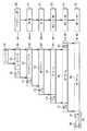
図1は、802.11準拠のWLANによるユーザ・データのための従来技術によるフレーミング・シーケンスを示す。図1に示したように、アプリケーション層150、伝送制御プロトコル(TCP)層151、インターネット・プロトコル(IP)層152、論理リンク制御(LLC)層153(データ・リンク層のサブ・レイヤ)、メディア・アクセス制御(MAC)層154(これもまたデータ・リンク層のサブ・レイヤ)、および物理(PHY)層155(物理層)として、6つのプロトコル階層が示されている。ユーザ・データ101はアプリケーション層150に提供され、アプリケーション層でアプリケーション層ヘッダ110が追加されてアプリケーション・データ102が生成される。アプリケーション・データ102はTCP層151に提供され、TCP層でアプリケーション・データ102にTCP・ヘッダ111が追加されてTCPセグメント103が形成される。IP層152ではTCPセグメント103にIPヘッダ112が追加されてIPフレーム104が形成される。IPフレーム104は代表的なTCP/IPパケットであり、必ずしも802.11に準拠しないものも含め、多くのデータ・ネットワーク・アプリケーションで共通に使用されている。
FIG. 1 shows a prior art framing sequence for user data over an 802.11 compliant WLAN. As shown in FIG. 1, an
LLC層153は、MAC層154と上位層の間に統一されたインタフェースを提供して、TCP/IPパケットを送信するために使用されるWLANのタイプの透過性を提供する。LLC層153は、IPフレーム104にLLCヘッダ113としてこのインタフェース情報を追加してLLCフレーム105を形成する。
The
802.11準拠のWLANでは、物理デバイスは無線機であり物理通信媒体は自由空間である。MACデバイスおよびPHY層信号制御デバイスは、2つのネットワーク・ステーションが正しいフレーム・フォーマットおよびプロトコルで通信することを保証する。WLANの802.11標準は、2つ(またはそれ以上の)ピアのPHYデバイス間および関連するMACデバイス間の通信プロトコルを定義する。802.11WLANデータ通信プロトコルによれば、MACデバイスとPHYデバイスの間で送信される各パケット・フレームは、PHYヘッダ、MACヘッダ、MACデータ、およびエラー・チェック・フィールドを有する。802.11準拠WLANシステムのMAC層フレームの代表的フォーマットでは、LLCフレーム105にMACヘッダ114およびフレーム・チェック・シーケンス(FCS)115を追加してMACフレーム106を形成する。MACヘッダ114は、フレーム制御、継続時間識別番号(ID)、送信元(すなわちMAC層)および宛先アドレス、ならびにデータ・シーケンス制御(番号)の各フィールドを含む。ユーザ・データは大きなユーザ・データ・ストリームの一部なので、データ・シーケンス制御フィールドがシーケンス番号情報を提供して、受信機がデータ・シーケンス順序を再構築することを可能にする。
In an 802.11 compliant WLAN, the physical device is a radio and the physical communication medium is free space. The MAC device and the PHY layer signal control device ensure that the two network stations communicate with the correct frame format and protocol. The WLAN 802.11 standard defines a communication protocol between two (or more) peer PHY devices and between associated MAC devices. According to the 802.11 WLAN data communication protocol, each packet frame transmitted between the MAC device and the PHY device has a PHY header, a MAC header, MAC data, and an error check field. In a typical format of the MAC layer frame of the 802.11 compliant WLAN system, a
PHY層155は、MACフレーム106にPHYヘッダを追加することによって物理層パケット・フレーム107を形成する。PHYヘッダ118は、プリアンブル116およびPLCP(physical-layer convergence protocol)ヘッダ117を含む。PLCPヘッダ117は、例えばPHY層のデータ・レートやデータ長を識別する。また、プリアンブル116は、i)着信フレームを検出/同期し、ii)送信機と受信機の間のチャネル特性を推定するために受信装置によって使用される。
The
802.11標準によるデバイス間の典型的な通信では、各MAC層フレームは、最初の物理層フレームが送信された後のSIFS(short interframe space)期間に送信されるACKメッセージ(またはACKフレーム)によって確認される。802.11e標準仕様では、確認応答メッセージがまったく送信されない「No−ACK」など、いくつかの代替確認応答方法が指定されている。可能な他の方法には、1つのブロックACKメッセージで複数のデータ・フレームを確認できるブロックACKの変形形態がある。このブロックACKメッセージは、ブロックACK要求の直後(即時ブロックACK)または別のコンテンション期間の後(遅延ブロックACK)に送信される。 In typical communication between devices according to the 802.11 standard, each MAC layer frame is transmitted by an ACK message (or ACK frame) transmitted in a short interframe space (SIFS) period after the first physical layer frame is transmitted. It is confirmed. The 802.11e standard specification specifies several alternative acknowledgment methods, such as “No-ACK” in which no acknowledgment message is sent. Another possible method is a variant of block ACK in which multiple data frames can be confirmed with one block ACK message. This block ACK message is sent immediately after the block ACK request (immediate block ACK) or after another contention period (delayed block ACK).
所与の層で、802.11WLANシステムの達成可能な最大スループットに影響を与える1つの要素は、(例えば、ユーザ・データ101などの)ペイロードを運ぶフレームの長さである。比較的良いチャネル品質の場合は、フレーム・サイズの増加に伴いスループット効率も向上する。スループット効率の向上は、その層のオーバヘッド(例えば、ヘッダ、チェックサムなど)が固定サイズであることに関連する。その理由は、フレーム・サイズが増加するに伴い、オーバヘッドとデータの比が低下するからである。従来技術の802.11準拠のWLANのなかには、各送信されるPHY層パケット・フレームがただ1つのMACフレームだけを含むものもある。MACフレームは、プローブ要求フレームや確認応答フレームなどの制御または管理フレームであってもよい。他のMACフレームとしては、上位層ユーザ・データのただ1つのパケットだけを含むデータ・フレームであってもよい。MACヘッダ・フィールドやFCSフィールドはパケット・オーバヘッドに含まれる。
IEEE 802.11プロトコルの効率は、高い物理層データ・レートが使用されたときに低下する。このことは、例えばプリアンブル、IFS(inter-frame space)タイミング、ヘッダ情報など、PHY層およびMAC層レベルのいくつかのオーバヘッド源によって引き起こされ、また確認応答パケットによっても引き起こされる。IEEE 802.11では、バースト・パケット送信やブロックACKメッセージングなど、効率を向上するためのいくつかの方法が提案されている。しかし、これらの方法を使用しても、162Mbit/s以上のPHY層レートの使用を効率的にすることはできない。 The efficiency of the IEEE 802.11 protocol is degraded when high physical layer data rates are used. This is caused by several PHY and MAC layer level overhead sources, such as preamble, inter-frame space (IFS) timing, header information, etc., and also by acknowledgment packets. In IEEE 802.11, several methods for improving efficiency have been proposed, such as burst packet transmission and block ACK messaging. However, even if these methods are used, the use of a PHY layer rate of 162 Mbit / s or more cannot be made efficient.
PHY層において、オーバヘッドはPHYフレーム・プリアンブルおよびPLCPヘッダによってもたらされるが、どちらも各MACデータ・フレームに対して一定のサイズである。したがって、パケットあたりに運ばれるデータ量がより大きい場合には、メディアはより有効に使用されることになる。また、PHY層フレーム・オーバヘッドは一般にサイズ(すなわち、バイト数)ではなく時間が一定なので、PHY層フレーム・オーバヘッドはより高いデータ・ビット・レートとともに変化しない。送信される所与の量のユーザ・データに対するPHYフレームの数を削減することで、大きな効率の向上がもたらされる。PHY層オーバヘッドは、ユーザ・データの送信には直接関係しない(例えば、プローブ要求フレーム、RTS/CTSフレーム、確認応答フレームなどの)MACフレームを含む、送信される各MACフレームごとに含まれるので、個別に送信されるMACフレームの数を削減することによって効率が向上する。PHYフレームの数を削減することはまた、MACコンテンション・オーバヘッドを削減することにもなる。 In the PHY layer, the overhead is brought about by the PHY frame preamble and the PLCP header, both of which are a fixed size for each MAC data frame. Therefore, if the amount of data carried per packet is larger, the media will be used more effectively. Also, since the PHY layer frame overhead is generally time rather than size (ie, number of bytes), the PHY layer frame overhead does not change with higher data bit rates. Reducing the number of PHY frames for a given amount of user data being transmitted provides a significant efficiency improvement. Since the PHY layer overhead is included for each transmitted MAC frame, including MAC frames (eg, probe request frames, RTS / CTS frames, acknowledgment frames, etc.) that are not directly related to the transmission of user data. Efficiency is improved by reducing the number of MAC frames transmitted separately. Reducing the number of PHY frames will also reduce MAC contention overhead.
本発明の実施形態によれば、パケット・ネットワークは、フレーム集約を使用して所与の量のユーザ・データを送信するために使用される物理層フレームの数を削減する。このパケット・ネットワークは、1つまたは複数の802.11標準に従って動作する無線ローカル・エリア・ネットワーク(WLAN)の物理(PHY)層とメディア・アクセス制御(MAC)層を使用する。フレーム集約は、いくつかの個別の上位層フレームとユーザ・データや管理/制御データなどのデータとを1つのPHY層フレームに結合し、送信されるPHY層フレームあたりのユーザ・データの量を増やす。フレーム集約により、(例えば、プリアンブルおよびPLCPヘッダ・オーバヘッドなどの)PHY層オーバヘッドおよび(例えば、コンテンション・オーバヘッドなどの)MACオーバヘッドの両方が削減されることによって効率が向上する。 According to embodiments of the present invention, a packet network reduces the number of physical layer frames used to transmit a given amount of user data using frame aggregation. This packet network uses the physical (PHY) layer and the media access control (MAC) layer of a wireless local area network (WLAN) that operates according to one or more 802.11 standards. Frame aggregation combines several individual upper layer frames and data such as user data and management / control data into one PHY layer frame, increasing the amount of user data per PHY layer frame transmitted. . Frame aggregation improves efficiency by reducing both PHY layer overhead (eg, preamble and PLCP header overhead) and MAC overhead (eg, contention overhead).
本発明の一例示的実施形態によると、集約データのフレームは(a)第1の層に従って1つまたは複数のユーザ・データ・フレームを集約ユーザ・データに結合し、(b)集約層で、集約ユーザ・データに少なくとも1つのヘッダを追加することによって、集約ユーザ・データから各々が第2の層に従うフォーマットを有する1つまたは複数のサブフレームを生成し、(c)第3の層に従って1つまたは複数のサブフレームから集約フレームを形成することによって生成される。 According to an exemplary embodiment of the invention, the frame of aggregated data (a) combines one or more user data frames with aggregated user data according to the first layer, and (b) at the aggregated layer, Generating one or more subframes each having a format according to the second layer from the aggregated user data by adding at least one header to the aggregated user data; and (c) 1 according to the third layer It is generated by forming an aggregate frame from one or more subframes.
本発明の他の例示的実施形態によると、集約データのフレームは(a)複数の集約フォーマットのうちの1つに基づいて、1つまたは複数のユーザ・データ・フレームを集約ユーザ・データに結合し、(b)集約層で、集約ユーザ・データに少なくとも1つのヘッダを追加することによって、集約ユーザ・データから1つまたは複数のサブフレームを生成し、(c)1つまたは複数のサブフレームから集約フレームを形成することによって生成される。
本発明の他の態様、特徴、および利点は、以下の詳細な説明、別添の特許請求の範囲、および添付の図面からより完全に明らかになるであろう。
According to another exemplary embodiment of the present invention, the frame of aggregated data (a) combines one or more user data frames with aggregated user data based on one of a plurality of aggregate formats. And (b) generating one or more subframes from the aggregated user data by adding at least one header to the aggregated user data at the aggregation layer, and (c) one or more subframes Is generated by forming an aggregated frame from
Other aspects, features, and advantages of the present invention will become more fully apparent from the following detailed description, the appended claims, and the accompanying drawings.
本発明の例示的実施形態によると、フレーム集約によって、例えば所与の量のユーザ・データを送信するために使用される物理層フレームの数が削減される。本明細書で説明する例示的実施形態は、1つまたは複数のIEEE 802.11標準によるシステムに関する。この標準は、無線ローカル・エリア・ネットワーク(WLAN)の物理(PHY)層およびメディア・アクセス制御(MAC)層を定義するものである。しかし、当業者なら本明細書の教示を他のパケットベース通信ネットワークに適用できるはずである。本明細書に記載のように、論理リンク制御(LLC)層、インターネット・プロトコル(IP)層、および伝送制御プロトコル/ユーザ・データグラム・プロトコル(TCP/UDP)層などの上位層は(例えば802.11などの)下位層標準の制御の外に置くことができる。したがって本発明の例示的実施形態では、フレーム集約を使用してユーザ・データを含む個別の上位層フレームのいくつかを1つのPHYレベル・フレームに結合することによって、送信するPHYフレームあたりのユーザ・データ量を増加させる。フレーム集約では、(例えば、プリアンブルやPLCPヘッダのオーバヘッドなどの)PHYオーバヘッドおよび(例えば、コンテンション・オーバヘッドなどの)MACオーバヘッドの両方を削減することによって効率を向上させる。 According to an exemplary embodiment of the invention, frame aggregation reduces the number of physical layer frames used, for example, to transmit a given amount of user data. The exemplary embodiments described herein relate to a system according to one or more IEEE 802.11 standards. This standard defines the physical (PHY) layer and the media access control (MAC) layer of a wireless local area network (WLAN). However, those skilled in the art should be able to apply the teachings herein to other packet-based communication networks. As described herein, higher layers such as the Logical Link Control (LLC) layer, the Internet Protocol (IP) layer, and the Transmission Control Protocol / User Datagram Protocol (TCP / UDP) layer (eg, 802 Can be outside the control of lower layer standards (such as .11). Thus, in an exemplary embodiment of the present invention, user aggregation per PHY frame to be transmitted by combining several individual upper layer frames containing user data into one PHY level frame using frame aggregation. Increase the amount of data. Frame aggregation improves efficiency by reducing both PHY overhead (eg, preamble and PLCP header overhead) and MAC overhead (eg, contention overhead).
本発明の例示的実施形態によるフレーム集約では、以下のA)〜C)に対していくつかのフレームを集約することができる。すなわち、A)同一の宛先アドレスを有し同一のPHY層データ・レートを有するフレーム、B)1つまたは複数の宛先アドレスを有し同一のPHY層データ・レートを有するフレーム、およびC)1つまたは複数の宛先アドレスを有し、それぞれのフレームがいくつかの可能なPHY層データ・レートのうちの1つを有するフレーム。 In frame aggregation according to an exemplary embodiment of the present invention, several frames can be aggregated for the following A) to C). A) frames with the same destination address and the same PHY layer data rate, B) frames with one or more destination addresses and the same PHY layer data rate, and C) one Or a frame with multiple destination addresses, each frame having one of several possible PHY layer data rates.
同一の宛先アドレスを有し、かつ同一のPHY層データ・レートを有するフレームを集約する場合を、本明細書では「ケースA」と呼ぶ。「ケースA」は、従来技術のMAC層およびPHY層の動作の変更を、ほとんどまたはまったく必要としないものであり、好ましくは、多数のフレームが同一の宛先アドレスを指定するときに使用できる。例えば、基本サービス・セット(BSS)のアップリンク通信(トラフィック)には、一般にケースAによるフレーム集約を使用することができる。 A case where frames having the same destination address and the same PHY layer data rate are aggregated is referred to as “case A” in this specification. “Case A” requires little or no modification of prior art MAC and PHY layer operations, and can preferably be used when multiple frames specify the same destination address. For example, frame aggregation according to Case A can generally be used for basic service set (BSS) uplink communications (traffic).
異なる宛先アドレスを有し、かつ同一のPHY層データ・レートを有するフレームを集約する場合を本明細書では「ケースB」と呼ぶ。「ケースB」は一般に、ステーション(STA)、または異なる宛先のSTAにデータを送信するアクセス・ポイント(AP)によって使用される。しかし、フレームが1つのデータ・レートで送信されるので、好ましくは、異なる宛先STAは同一のチャネル条件を有する。ケースBでは、スケジューリング方法によって集約すべきフレームを選択し、送信をスケジュールする。このスケジューリング方法は、実施形態によっては異なる送信優先度を有するパケットを考慮することができる。 A case where frames having different destination addresses and having the same PHY layer data rate are aggregated is referred to as “case B” in this specification. “Case B” is typically used by a station (STA) or an access point (AP) that transmits data to a STA of a different destination. However, since the frames are transmitted at one data rate, preferably different destination STAs have the same channel conditions. In case B, frames to be aggregated are selected by the scheduling method, and transmission is scheduled. This scheduling method can take into account packets with different transmission priorities in some embodiments.
1つまたは複数の宛先アドレスを有し、かつ各々がいくつかの可能なPHY層データ・レートのうちの1つを有するフレームを集約する場合を、本明細書では「ケースC」と呼ぶ。「ケースC」は、より大きな柔軟性を提供し、一般にケースAやケースBのフレーム集約と比べて無線メディアのより高い使用効率を提供する。無線メディアのより高い使用効率は、すべてのフレームが随時最適のデータ・レートで送信できることによってもたらされる。 The case of aggregating frames having one or more destination addresses and each having one of several possible PHY layer data rates is referred to herein as “Case C”. “Case C” provides greater flexibility and generally provides higher usage efficiency of wireless media compared to case A and case B frame aggregation. Higher usage efficiency of the wireless media comes from the fact that every frame can be transmitted at an optimal data rate from time to time.
本発明の例示的実施形態によると、PHY層およびMAC層に関してフレーム集約を論理的に配置することができる。第1にフレーム集約は、例えばLLC層とMAC層の間など、MAC層の上位で(すなわち、MAC層の動作の前に)実施することができる。第2にフレーム集約は、例えばMAC層とPHY層の間、またはPHY層内など、MAC層の下位で実施することができる。第3にフレーム集約は、MAC層自体の中で実施することができる。 According to an exemplary embodiment of the present invention, frame aggregation can be logically arranged with respect to the PHY layer and the MAC layer. First, frame aggregation can be performed above the MAC layer (ie, before operation of the MAC layer), eg, between the LLC layer and the MAC layer. Second, frame aggregation can be implemented below the MAC layer, for example, between the MAC layer and the PHY layer, or within the PHY layer. Third, frame aggregation can be performed within the MAC layer itself.
MAC層の上位でのフレーム集約はMAC層およびPHY層の動作の小変更をともなうが、例えば、ネットワーク装置に現在存在するソフトウェア・ドライバを更新することによって実現できる。既存のネットワーク装置に中間層を論理的に実装してフレーム集約を実施させることによって、MAC層やLLC層の動作にほとんど、またはまったく変更を加えないようにすることもできる。例えば図2に示したように、LLC層210のLLCフレーム201(1)〜201(N)を、中間集約層203によってダミーLLCフレーム202に結合することができる。ただし、Nは正の整数である。ダミーLLCフレーム202はMAC層204に渡され、MAC層でMACヘッダ205とMAC層FCS206が追加されてMACフレーム207が形成される。PHY層208では、MACフレーム207にプリアンブル209およびPLCPヘッダ210が追加されてPHYパケット211が形成される。
Frame aggregation above the MAC layer involves a small change in the operation of the MAC layer and the PHY layer, and can be realized, for example, by updating a software driver that currently exists in the network device. It is also possible to make little or no change to the operation of the MAC layer or LLC layer by logically implementing an intermediate layer in an existing network device to perform frame aggregation. For example, as shown in FIG. 2, the LLC frames 201 (1) to 201 (N) of the
MAC層の下位でのフレーム集約では、いくつかのMACフレームが1つのダミーMACフレームに形成され、次いでそれがPHY層によってパケット化される。MAC層の下位のフレーム集約を用いると、各MACフレームにフレーム・チェックサムなどのエラー検出情報が含まれるので他のフレームとは独立に各LLCフレームを検証することができる。フレーム・チェックサムは、LLCフレームに追加された、例えばFCSフィールドなどのエラー制御フィールド中に置かれる。現在の802.11準拠のWLANシステムでは、MACレベルでのエラー検出はサポートされるが、必ずしもエラー訂正まではサポートされない。しかし、当業者なら、単純なエラー検出の代わりに、当技術分野で既知のいくつかのエラー訂正方法のいずれかを使用することができるはずである。したがって本明細書に記載の例示的実施形態では、i)エラー検出機能が使用されているのか、ii)エラー検出および訂正機能が使用されているのかを識別するために「エラー訂正/検出」という用語を使用する。また、個別のMACフレームは各々のヘッダおよび宛先アドレス情報付きで送信されるので、MACフレームを別々の宛先に送信することもできる。図3は、本発明の第2の例示的実施形態によるMAC層の下位でのフレーム集約を示す。 In frame aggregation below the MAC layer, several MAC frames are formed into one dummy MAC frame, which is then packetized by the PHY layer. When frame aggregation below the MAC layer is used, error detection information such as a frame checksum is included in each MAC frame, so that each LLC frame can be verified independently of other frames. The frame checksum is placed in an error control field, such as an FCS field, added to the LLC frame. In current 802.11 compliant WLAN systems, error detection at the MAC level is supported, but error correction is not necessarily supported. However, those skilled in the art should be able to use any of several error correction methods known in the art instead of simple error detection. Accordingly, in the exemplary embodiment described herein, it is referred to as “error correction / detection” to identify whether i) an error detection function is used or ii) an error detection and correction function is used. Use terminology. In addition, since the individual MAC frame is transmitted with each header and destination address information, the MAC frame can be transmitted to different destinations. FIG. 3 illustrates frame aggregation below the MAC layer according to a second exemplary embodiment of the present invention.
LLC層302のLLCフレーム301(1)〜301(M)がMAC層305に渡される。ただし、Mは正の整数である。各LLCフレーム301(n)は、MACヘッダ303(n)およびMAC FCS304(n)が追加されてMACサブフレーム316(n)の形に形成される。MACサブフレーム316(1)〜316(M)は、ダミーMACフレーム306の形に結合される。次いで中間集約層307は、ダミーMACフレーム306にオプションの、i)ダミー・ヘッダ308、および/またはii)転送エラー訂正/検出(FEC)フィールド309を追加して集約MACフレーム310を形成する。PHY層311では、集約MACフレーム310にプリアンブル313およびPLCPヘッダ314が追加されてPHYパケット312が形成される。
The LLC frames 301 (1) to 301 (M) of the
図3には、オプションのダミー・ヘッダ308およびFECフィールド309が示されている。ダミー・ヘッダ308を使用して、ダミーMACフレーム306に含まれるMACサブフレーム316(1)〜316(M)の数(例えば、M)やサイズ(すなわち、長さ)を示すことができる。FECフィールド309を使用して、受信機でビット・エラーを訂正することによってMACサブフレーム316(1)〜316(M)を正しく受信する確率を高めることもできる。あるいは、複数のFECフィールドを使用して、ダミーMACフレーム306の最後または各MACフレーム316(1)〜316(M)の内部に追加することもできる。各MACサブフレームが異なる宛先を有するときは、(例えば、遅延ACK(delayed-ACK)メッセージ交換などの)修正された応答確認方法が使用される。
In FIG. 3, an optional dummy header 308 and
図4は、本発明の第2の例示的実施形態の代替実施形態によるPHY層内でのフレーム集約を示す。LLC層402のLLCフレーム401(1)〜401(M)がMAC層405に渡される。MAC層405は、MACヘッダ403(n)およびMAC FCS404(n)をLLCフレーム401に追加してMACサブフレーム406(n)を形成する。次いで、MACサブフレーム406(1)〜406(M)がPHY層407に渡される。PHY層407は、PLCPヘッダ409(n)を各対応するMACサブフレーム406(n)に追加してPHYサブフレーム410(n)を形成する。PHYサブフレーム410(1)〜410(M)は連結され、連結されたPHYサブフレームにプリアンブル408が追加されてPHYパケット411が形成される。
FIG. 4 shows frame aggregation in the PHY layer according to an alternative embodiment of the second exemplary embodiment of the present invention. The LLC frames 401 (1) to 401 (M) of the
図4に示したように、複数のPHYフレームがプリアンブルを除いて連結されるので、個々のMACフレームを異なるデータ・レートで送信し、各MACフレームを個別に受信することが可能になる。図4の実施形態のある実装では、比較的性能の劣るチャネル状況のSTAが低いデータ・レートを正しく受信できるように、含まれるMACフレームをデータ・レートの昇順に並べることができる。 As shown in FIG. 4, since a plurality of PHY frames are concatenated except for the preamble, it is possible to transmit individual MAC frames at different data rates and receive each MAC frame individually. In some implementations of the embodiment of FIG. 4, included MAC frames can be ordered in ascending order of data rates so that STAs with relatively poor channel conditions can correctly receive low data rates.
MAC層内のフレーム集約は、本発明のフレーム集約と既存のMAC層動作を統合し、比較的大きな柔軟性を提供する。MAC層内のフレーム集約によって、個別のMACフレームの検出も可能になる。MAC層内のフレーム集約は、本発明によるMAC集約フレーム・フォーマットを含むことができる。このMAC集約フレーム・フォーマットは、いくつかの上位層データ・フレームをそれぞれ独立に受信しデコードすることができるような形に組み込んだものであり、このフォーマットを用いることで各上位層データ・フレームを異なる宛先の受信機に送信することが可能になる。さらに、MAC層はPHY層の動作を制御するので、集約フレームの各部分を異なるPHYデータ・レートで送信して、各フレームを所望のデータ・レートで送信することも可能にする。 Frame aggregation within the MAC layer integrates the frame aggregation of the present invention with existing MAC layer operations and provides relatively great flexibility. Frame aggregation within the MAC layer also enables detection of individual MAC frames. Frame aggregation within the MAC layer may include a MAC aggregation frame format according to the present invention. This MAC aggregated frame format incorporates a number of higher layer data frames that can be received and decoded independently. By using this format, each upper layer data frame is It becomes possible to transmit to receivers of different destinations. Furthermore, since the MAC layer controls the operation of the PHY layer, each part of the aggregated frame can be transmitted at a different PHY data rate, allowing each frame to be transmitted at a desired data rate.
図5は、本発明の第3の例示的実施形態によるMAC層内でのフレーム集約を示す。LLC層502でLLCフレーム501(1)〜501(N)が生成され、それがMAC層503に渡される。MAC層503は、2つの動作を含む。すなわち、第1の動作では、LLCフレーム501(1)〜501(N)からMACサブフレーム506(1)〜506(N)が生成される。第2の動作では、MACサブフレーム506(1)〜506(N)からMACフレーム507が生成される。MACサブフレーム506(n)は、1つまたは複数のIEEE 802.11標準に従って、対応するMACヘッダ504(n)およびMAC FCS505(n)を追加することによって生成される。
FIG. 5 illustrates frame aggregation within the MAC layer according to a third exemplary embodiment of the present invention. LLC frames 501 (1) to 501 (N) are generated in the
MACフレーム507は、MACサブフレーム506(1)〜506(N)をデータ・レートに従ってグループ化し、次いで先頭にMAC記述子508を追加することによって形成することができる。MAC記述子508は、MACフレーム507の残りの部分のインデックス情報を提供するフィールドである。MAC記述子508はまた、MACフレーム507内部の1つまたは複数のMACサブフレーム506(1)〜506(N)の位置、長さ、および宛先を指定することもできる。含まれるMACサブフレーム506(1)〜506(N)すべての宛先アドレスはMACフレーム507の先頭に配置されるので、受信機はMAC記述子508をデコードすることによって、含まれるMACサブフレーム506(1)〜506(N)の1つまたは複数がその受信機に宛てられたものかどうかを判断することができる。受信機はこの情報を使用して、MACサブフレームが見込めないときにはリスニング・モードを中断し、(例えば、使用電力を節約するなど)より効率的な動作をもたらすこともできる。
The
MACサブフレーム506(1)〜506(N)はデータ・レートごとにグループ化され、MACフレーム部509、510、および511に連結される。図4に示した実施形態と同様に、悪いチャネル状況にある受信機が、低いデータ・レートのMACサブフレームを正しく受信できるように、MACサブフレーム506(1)〜506(N)はデータ・レートの昇順に並べられる。したがって、好ましくは、MAC記述子508は含まれる最も低いデータ・レートで送信される。図5の場合は、データ・レートX<データ・レートY<データ・レートZである。
The MAC subframes 506 (1) to 506 (N) are grouped for each data rate, and are concatenated to the
MACフレーム507はPHY層512に渡され、そこでPHYパケット518が形成される。PHY層512は、MAC記述子508とMACフレーム部509をグループにしてPHYデータ・レートX部515を形成することによってPHYパケット518を形成する。MACフレーム部510および511はそれぞれ直接PHYデータ・レートY部516およびZ部517にマップされる。PHYデータ・レートX部515、Y部516、Z部517は連結され、プリアンブル513およびPLCPヘッダ514が追加されてPHYパケット518が生成される。
The
集約フレームが複数のデータ・レートで送信される場合、すなわち1つまたは複数のMACフレーム部が他と異なるデータ・レートで送信される場合は、フレームのどの部分にどのデータ・レートを使用すべきかについての情報をPLCPヘッダ514で運ぶことができる。PLCPヘッダ514はMACフレーム518の前方(すなわち、プリアンブルの直後)に配置されるように示されているが、代替実施形態ではPLCPヘッダ・フィールドをそのPLCPヘッダ・フィールドに記載されたMACサブフレーム部の前、例えば各PHYデータ・レートX部515、Y部516、およびZ部517の直前に配置することもできる。
Which data rate should be used for which part of the frame if the aggregated frame is transmitted at multiple data rates, i.e. one or more MAC frame parts are transmitted at different data rates Information about can be carried in the
図2〜5の例示的実施形態の動作はコンピュータによってシミュレートすることが可能であり、メディア効率として測定された例示的実施形態の性能が様々な条件で示される。メディア効率は、ポイントツーポイント・リンクでの比較的理想的な条件下における達成可能な最大スループットを比較することによって図6〜8に示される。このシミュレーションに使用される条件は、i)各交換シーケンスが、1つの集約フレームとその後に続く(ブロックACKではない)通常のACKフレームからなること、ii)1つの集約フレームに含まれる全てのデータ・フレームが同一のデータ・レート(例えば、54−、216−、および324−Mbit/s)で送信され、全てのデータ・フレームが1500byteの大きさであること、iii)ACKフレームが54Mbit/sで送信され、正規の802.11aプリアンブルおよびPLCPヘッダを有し、かつ802.11aに定められた値と等価なタイミング(SIFS(short interframe space)、DIFS(distributed interframe space)、およびスロット・タイム)を使用すること、iv)コンテンションが、各フレーム交換ごとのあるスロットの「最適」値になるように選択されること、およびv)衝突およびビット/パケット・エラーがないことである。 The operation of the exemplary embodiment of FIGS. 2-5 can be simulated by a computer, and the performance of the exemplary embodiment measured as media efficiency is shown in various conditions. Media efficiency is illustrated in FIGS. 6-8 by comparing the maximum achievable throughput under relatively ideal conditions on a point-to-point link. The conditions used for this simulation are: i) each exchange sequence consists of one aggregated frame followed by a normal ACK frame (not a block ACK), ii) all the data contained in one aggregated frame Frames are transmitted at the same data rate (eg 54-, 216-, and 324-Mbit / s) and all data frames are 1500 bytes in size, iii) ACK frames are 54 Mbit / s Sent with a regular 802.11a preamble and PLCP header, and equivalent to the values defined in 802.11a (SIFS (short interframe space), DIFS (distributed interframe space), and slot time) Iv) Contention replaces each frame It is selected to be "optimal" value of the slot with, and v) is that there are no collisions and bit / packet error.
図6、7、および8はそれぞれ、54−Mbit/s、216−Mbit/s、および324−Mbit/s PHY層データ・レートに対する最大スループット対集約されたフレーム数を示す。図6、7、および8はそれぞれ、(塗りつぶしたひし形でMAC層集約が示される)図3、(塗りつぶした四角でPHY層集約が示される)図4、および(塗りつぶした三角でMAC(フレーム)記述子付きのMAC層集約が示される)図5に示された実施形態での最大スループットを示す。 FIGS. 6, 7, and 8 show the maximum throughput versus the number of frames aggregated for 54-Mbit / s, 216-Mbit / s, and 324-Mbit / s PHY layer data rates, respectively. FIGS. 6, 7 and 8 respectively show FIG. 3 (with filled diamonds showing MAC layer aggregation), FIG. 4 (with filled squares showing PHY layer aggregation), and (filled triangles with MAC (frame)). FIG. 6 shows the maximum throughput in the embodiment shown in FIG. 5 (MAC layer aggregation with descriptors is shown).
図3のMAC層集約は、含まれるMACサブフレームをすべて追加の保護フィールド、フレーム記述子、またはPLCPヘッダなしで順次連結する。このシミュレーションでは、ダミー・ヘッダおよびFECフィールドは使用しない。使用した集約フォーマットは、ケースAの単一宛先フレーム集約の場合を表す。図4のPHY層集約は、含まれるMACサブフレームがすべて各々のデータ・レートで送信されるので、このシミュレーションはケースCの複数データ・レートの場合のフレーム集約を表す。図6〜8ではそれぞれ、ただ1つのデータ・レートだけが実際に使用される。フレーム記述子を使用する図5のMAC層集約は、ケースBで、ただ1つのデータ・レートおよび(したがって、必然的に同一のデータ・レートを使用する)複数の宛先を使用する場合の集約を表す。図6〜8の各シミュレーションでは、ただ1つの宛先だけが使用される。 The MAC layer aggregation of FIG. 3 sequentially concatenates all included MAC subframes without any additional protection fields, frame descriptors, or PLCP headers. In this simulation, the dummy header and FEC field are not used. The aggregation format used represents the case of single destination frame aggregation in Case A. The PHY layer aggregation of FIG. 4 represents the frame aggregation for case C multiple data rates because all included MAC subframes are transmitted at each data rate. In each of FIGS. 6-8, only one data rate is actually used. The MAC layer aggregation of FIG. 5 using frame descriptors is the case B with aggregation when using only one data rate and multiple destinations (thus necessarily using the same data rate). To express. In each simulation of FIGS. 6-8, only one destination is used.
図6、7、および8に示されたシミュレーション結果は、より上位層のフレームが1つの集約フレームに結合されるほど最大スループットが高くなることを示す。また、集約できる上位層フレームの数が少ない場合には、特により高いPHY層データ・レートの場合に、最大スループットがかなり低下する。 The simulation results shown in FIGS. 6, 7, and 8 show that the maximum throughput increases as higher layer frames are combined into one aggregated frame. Also, if the number of higher layer frames that can be aggregated is small, the maximum throughput is significantly reduced, especially at higher PHY layer data rates.
宛先ステーションが異なるフレームを集約できる集約方法は、集約に使用できるフレームが増える可能性が高まるので、所望のスループットに達する可能性がより高くなる。送信されるフレームの各部分が異なるデータ・レートを有する集約方法により、高いメディア効率に達する可能性が高まる。その理由は、この方法により、集約されたフレームをまったく異なるチャネル条件を有するステーションに送信することが可能になり、したがって集約に多数のフレームを使用できる可能性が高まるからである。 Aggregation methods in which the destination stations can aggregate different frames are more likely to reach the desired throughput because there is an increased likelihood that more frames can be used for aggregation. Aggregation methods where each portion of the transmitted frame has a different data rate increases the likelihood of reaching high media efficiency. The reason is that this method allows aggregated frames to be sent to stations with completely different channel conditions, thus increasing the possibility of using multiple frames for aggregation.
達成可能な最大スループットは、集約に使用できるフレームの数に依存する。複数の宛先フレームを有するフレーム集約を用いると集約に使用できるフレームの数が増える。しかし、802.11 WLANでは、一般にBSSのAPは複数のSTAに向けて送信するが、STAは1つまたは2つのAPにだけ送信する。したがって、複数の宛先を用いるこのタイプのフレーム集約は、一般に複数のSTAに向けて送信するAP用として使用される。 The maximum achievable throughput depends on the number of frames that can be used for aggregation. The use of frame aggregation with multiple destination frames increases the number of frames that can be used for aggregation. However, in 802.11 WLANs, BSS APs typically transmit to multiple STAs, but STAs only transmit to one or two APs. Therefore, this type of frame aggregation with multiple destinations is generally used for APs that send to multiple STAs.
したがって、STAから各APへのアップリンク・トラフィックには、比較的簡単なフレーム集約の方法を使用できるので、1つの宛先(結果的に1つのPHY層データ・レート)を有するフレームだけを1つのフレームに集約することが可能になる。 Therefore, for uplink traffic from the STA to each AP, a relatively simple method of frame aggregation can be used, so only frames with one destination (and consequently one PHY layer data rate) can be It can be aggregated into frames.
図9〜12は、数台のアクティブなSTAを用いてシミュレートしたBSSにおいて、いくつかの異なる構成に対する最大スループットを示したものである。図9〜12のシミュレーション結果では、各STAは異なるチャネル条件領域で動作し、したがって各STAは異なるデータ・レートで動作する。APは、1500バイトのデータ・フレームを各アクティブなSTAに送信する。各ステーションはいくつかのダウンリンク接続を有しており、APは各接続ごとに、各交換シーケンスあたり一定数のフレームを提供する。各データ・フレームおよび各MAC層確認応答は802.11aのPHY層フレーム・フォーマットに類似したフォーマットで送信されるが、拡張プリアンブル(+10μs)と拡張PLCPヘッダ(+4μs)を使用する。各シーケンスは、コンテンション用に3つのバックオフ・スロットを使用する。各ステーションは、各シーケンスごとにコンテンションあたり1つのTCP確認応答(60バイト・サイズ)で応答(アップリンク)する。ビット/パケット・エラーおよび/または衝突は考慮されない。即時ACKフレームが送信されるデータ・レートは、対応するデータ・フレームの1/2.25倍である。ブロックACKメッセージおよびブロックACK要求メッセージは対応するデータ・フレームと同一のデータ・レートで送信される。
図9〜12では、以下の7つの方法がシミュレートされ比較される。
Figures 9-12 show the maximum throughput for several different configurations in a BSS simulated with several active STAs. In the simulation results of FIGS. 9-12, each STA operates in a different channel condition region, and therefore each STA operates at a different data rate. The AP sends a 1500 byte data frame to each active STA. Each station has several downlink connections, and the AP provides a fixed number of frames for each exchange sequence for each connection. Each data frame and each MAC layer acknowledgment is sent in a format similar to the 802.11a PHY layer frame format, but uses an extended preamble (+10 μs) and an extended PLCP header (+4 μs). Each sequence uses three backoff slots for contention. Each station responds (uplinks) with one TCP acknowledgment (60 byte size) per contention for each sequence. Bit / packet errors and / or collisions are not considered. The data rate at which an immediate ACK frame is transmitted is 1 / 2.25 times that of the corresponding data frame. The block ACK message and the block ACK request message are transmitted at the same data rate as the corresponding data frame.
9-12, the following seven methods are simulated and compared.
第1の方法は、現在の802.11標準に従うもので、集約を使用しない(すなわち、各PHY層パケット・フレームは単一のMACフレームを含む)。この方法は、アップリンクおよびダウンリンク送信のどちらにも標準の即時ACKメッセージを使用する。このACKメッセージは、各データ・フレームの後、SIFS期間の経過後に送信される。 The first method follows the current 802.11 standard and does not use aggregation (ie, each PHY layer packet frame includes a single MAC frame). This method uses standard immediate ACK messages for both uplink and downlink transmissions. This ACK message is transmitted after each data frame and after the SIFS period.
第2の方法は、集約即時ACK(aggregated immediate ACK)を用いた単一宛先の集約を使用する。この集約即時ACKは、標準の即時ACKメッセージの拡張バージョンである。第2の方法では、APは、単一のステーション宛てのすべてのデータ・フレームを1つの集約フレームに結合する。STAはSIFS期間の後に集約即時ACKで応答する。アップリンク・チャネル(TCP−ACK)では集約無しのデータ・フレームを使用し、APは標準の即時ACKメッセージで応答する。 The second method uses single destination aggregation with an aggregated immediate ACK. This aggregated immediate ACK is an extended version of the standard immediate ACK message. In the second method, the AP combines all data frames destined for a single station into one aggregated frame. The STA responds with an aggregate immediate ACK after the SIFS period. The uplink channel (TCP-ACK) uses non-aggregated data frames and the AP responds with a standard immediate ACK message.
第3の方法は単一宛先の集約を使用するが、アップリンクおよびダウンリンクのどちらの送信方向にもブロックACKメッセージを使用する。ブロックACKメッセージおよびブロックACK要求メッセージは、802.11eに指定されているように、アップリンク方向およびダウンリンク方向のどちらの場合も集約フレームに含まれる。 The third method uses single destination aggregation, but uses block ACK messages for both uplink and downlink transmission directions. The block ACK message and the block ACK request message are included in the aggregated frame in both the uplink direction and the downlink direction as specified in 802.11e.
第4の方法は、単一PHYデータ・レートの集約を使用する。この場合、アップリンクは集約即時ACKメッセージを使用し、ダウンリンクはブロックACKメッセージを使用する。第4の方法では、APは、同一PHY層データ・レートを有するSTAのすべてのデータ・フレームを(複数の宛先を有する)1つの集約フレームに結合する。 The fourth method uses single PHY data rate aggregation. In this case, the uplink uses an aggregate immediate ACK message and the downlink uses a block ACK message. In the fourth method, the AP combines all data frames of STAs with the same PHY layer data rate into one aggregated frame (with multiple destinations).
第5の方法は、第4の方法に類似した単一レートの集約を使用するが、アップリンクおよびダウンリンクのどちらの送信方向にも遅延ブロックACK(delayed Block-ACK)メッセージを使用する。どちらの方向についても、ブロックACK要求メッセージおよびブロックACKメッセージは集約フレームに含まれる。 The fifth method uses a single rate aggregation similar to the fourth method, but uses a delayed block-ACK (delayed block-ACK) message in both uplink and downlink transmission directions. In both directions, the block ACK request message and the block ACK message are included in the aggregated frame.
第6の方法はマルチレート集約を使用する。この場合、アップリンク・チャネルは集約即時ACKメッセージを使用し、ダウンリンク・チャネルはブロックACKメッセージを使用する。第6の方法では、APは、図5のフォーマットを使用して、すべてのPHY層データ・レートに対するフレームを1つの集約フレームに結合する。各データ・レートごとに追加のPLCPヘッダが含まれるので、データ・レートの切換が可能になる(PLCPヘッダは、各フレームごとではなく、各レートごとにのみ含まれる)。 The sixth method uses multirate aggregation. In this case, the uplink channel uses an aggregate immediate ACK message and the downlink channel uses a block ACK message. In the sixth method, the AP combines the frames for all PHY layer data rates into one aggregated frame using the format of FIG. Since an additional PLCP header is included for each data rate, it is possible to switch the data rate (the PLCP header is included only for each rate, not for each frame).
第7の方法は、第6の方法に類似したマルチレート集約を使用する。ただし、アップリンクおよびダウンリンク・チャネル方向のどちらにも遅延ブロックACKメッセージを使用する。 The seventh method uses multirate aggregation similar to the sixth method. However, a delayed block ACK message is used for both uplink and downlink channel directions.
図9は、データ・フレームが324Mbit/s、即時ACKメッセージ・フレームが144Mbit/sの同一PHY層データ・レートでそれぞれ動作する3台のSTAを用いたBSSのシミュレーション結果を示す。各STAは1つのTCP接続を有し、各接続ごとに各集約フレームあたり3フレームを含む(すなわち、APは各サイクルの間に各ステーションに3フレームを送信する)。各STAは、各サイクルごとに1つのTCP ACKメッセージ・フレーム(すなわち、3つのダウンリンク・フレームごとに1つのACK)で応答する。 FIG. 9 shows a BSS simulation result using three STAs operating at the same PHY layer data rate with a data frame of 324 Mbit / s and an immediate ACK message frame of 144 Mbit / s. Each STA has one TCP connection and includes 3 frames for each aggregated frame for each connection (ie, the AP sends 3 frames to each station during each cycle). Each STA responds with one TCP ACK message frame for each cycle (ie, one ACK for every three downlink frames).
図10は、各STAが異なるPHY層データ・レートで動作すること以外は図9の構成と同じ場合のシミュレーション結果を示す。すなわち、1台のSTAが324Mbit/s(144Mbit/sのACKメッセージ・レート)で動作し、1台のSTAが216Mbit/s(96Mbit/sのACKメッセージ・レート)で動作し、1台のSTAが108Mbit/s(48Mbit/sのACKメッセージ・レート)で動作する場合である。 FIG. 10 shows the simulation results for the same configuration as in FIG. 9 except that each STA operates at a different PHY layer data rate. That is, one STA operates at 324 Mbit / s (144 Mbit / s ACK message rate), one STA operates at 216 Mbit / s (96 Mbit / s ACK message rate), and one STA. Is operating at 108 Mbit / s (ACK message rate of 48 Mbit / s).
図11は、各PHY層データ・レートごとに3台のSTAが動作し、計9台のSTAが存在することを除けば、図10と同じ構成の場合のシミュレーション結果を示す。
図12は、各STAが3つの接続をサポートすること、従ってAPが各サイクルごとに各ステーションあたり9つのフレームを送ることを除けば、図11と同じ構成の場合のシミュレーション結果を示す。
図9〜12に示したように、フレーム集約により、変化するチャネル条件下でのシステム性能に中程度から大幅な改善がもたらされる。
FIG. 11 shows a simulation result in the case of the same configuration as FIG. 10 except that three STAs operate for each PHY layer data rate and a total of nine STAs exist.
FIG. 12 shows the simulation results for the same configuration as FIG. 11 except that each STA supports 3 connections, and thus the AP sends 9 frames per station for each cycle.
As shown in FIGS. 9-12, frame aggregation provides a moderate to significant improvement in system performance under varying channel conditions.
本発明に従って、次に例示的集約フレーム・フォーマットを説明する。この集約フレーム・フォーマットを用いると、複数の宛先に対して複数のフレームを集約することが可能になる。この例示的集約フレーム・フォーマットは同一のPHY層データ・レートを有するフレームに対して説明されるが、当業者なら本明細書の教示を、例えば図5に示した例示的な第3の実施形態など、複数のデータ・レートを含む複数の宛先用のフレーム集約フォーマットに拡張できるはずである。 In accordance with the present invention, an exemplary aggregate frame format will now be described. When this aggregated frame format is used, a plurality of frames can be aggregated for a plurality of destinations. Although this exemplary aggregate frame format is described for frames having the same PHY layer data rate, those skilled in the art will understand the teachings herein, for example the exemplary third embodiment shown in FIG. Etc. and could be extended to a frame aggregation format for multiple destinations including multiple data rates.
本明細書で説明する例示的集約フレーム・フォーマットは、例えばフレーム集約を使用する装置とネットワークで共存する802.11準拠の装置との相互運用が可能である。本明細書で説明するPHY層データ・レートは54−Mbit/sよりも高いが、例示的集約フレーム・フォーマットは低いレート(例えば、802.11a標準または802.11g標準のデータ・レート)でも使用可能であり、したがって既存のMAC層実装と互換にできる。 The exemplary aggregate frame format described herein is interoperable with, for example, devices that use frame aggregation and 802.11-compliant devices that coexist in the network. The PHY layer data rate described herein is higher than 54-Mbit / s, but the exemplary aggregate frame format is also used at lower rates (eg, 802.11a standard or 802.11g standard data rates) Yes, and can therefore be compatible with existing MAC layer implementations.
可能な最高のメディア効率を達成するために、この例示的集約フレーム・フォーマットを用いると、例えば異なる宛先へのデータ・フレーム、(ブロック)ACKフレーム、管理用フレームなどあらゆるタイプのMACフレームを1つのPHYフレームに集約することが可能になる。省電力動作は、MACフレームの宛先アドレスがすべてPHYフレームの先頭に(すなわち、PLCPヘッダに隣接して)配置されるときに達成できる。受信装置(例えば、STA)によるトータルのリスニング時間を削減するために、最も多くのフレームが含まれる宛先アドレスがフレームの最後に来るように宛先アドレスが並べられる。 In order to achieve the highest possible media efficiency, this exemplary aggregate frame format can be used to combine all types of MAC frames, such as data frames to different destinations, (block) ACK frames, administrative frames, etc. It is possible to aggregate into PHY frames. Power saving operation can be achieved when the destination address of the MAC frame is all placed at the beginning of the PHY frame (ie, adjacent to the PLCP header). In order to reduce the total listening time by the receiving apparatus (for example, STA), the destination addresses are arranged so that the destination address including the most frames comes at the end of the frame.
集約フレーム(少なくともその一部)を正しく検出する可能性を高めるために、(例えば、MACサブフレームの長さを示すフィールドなど)集約フレーム中にオフセットを提供する、集約フレーム中のフィールドの数は比較的少ない。さらに、好ましくは、ビット・エラーまたはパケット・エラーによる弊害は、含まれるMACサブフレームの数が増えてもあるいはフレームのトータル長が長くなっても増加しない。 To increase the likelihood of correctly detecting an aggregated frame (at least part of it), the number of fields in the aggregated frame that provide an offset in the aggregated frame (eg, a field indicating the length of the MAC subframe) is Relatively few. Further, preferably, the adverse effects due to bit errors or packet errors do not increase even if the number of included MAC subframes increases or the total length of the frames increases.
図13はPHY層パケット1301の例示的集約フレーム・フォーマットである。パケット1301は、プリアンブル1302、PLCPヘッダ1303、集約データ・ユニット(ADU)1304、テイル(tail)・フィールド1305、およびオプションのパッド・ビット1306を含む。集約データ・ユニット(ADU)1304はまた、PLCPサービス・データ・ユニット(PSDU)とも呼ばれる。図13の集約フレーム・フォーマットは、図5の第3の例示的実施形態に従って生成されるPHY層パケットに使用することもできる。プリアンブル1302は、例えば802.11標準に基づくパケット検出に使用されるパターンである。プリアンブル1302を同期用に使用して、無線ゲインを決定し、クリアなチャネル・アセスメントを確立することができる。テイル・フィールド1305はPHY層パケット1301の終了を示す6ビットのパターンであり、このパターンを使用して受信機のViterbiデコーダをリセットすることができる。オプションのパッド・ビット1306は、PHY層パケット1301の長さを送信の既定値に合わせるために使用することができる。
FIG. 13 is an exemplary aggregate frame format for the
PLCPヘッダ1303は、信号フィールド1340、サービス・フィールド1341、およびオプションの予約フィールド1342を含む。信号フィールド1340は、レート・フィールド1343、オプションの予約フィールド1344、長さフィールド1345、パリティ・フィールド1346、およびテイル1347を含む。レート・フィールド1343はペイロードが送信されるレートを指定するために使用される。信号フィールド1340中の予約フィールド1344は、集約フレーム記述子1310(後述)に追加して、あるいはそれとは別に集約フレームの使用を指示するために使用できる。ただし、他の用途にも使用できる。長さフィールド1345は、(ビットの形で)次のペイロードの長さを指定する。パリティ・フィールド1346はPLCPヘッダ1303のビットを検証するために使用される(例えば、パリティ・チェック値などの)エラー訂正/検出値を含む。テイル・フィールド1347は信号フィールドの終わりを示す。また、このフィールドを使用して受信機のViterbiデコーダをリセットすることもできる。サービス・フィールド1341は現在予約されたフィールドであり、このフィールドを使用して802.11標準の送信機のスクランブラをリセットすることができる。オプションの予約フィールド1342は、例えば追加のPLCP情報および/または追加のプリアンブル構造など、追加のTGn情報のために予約されている(TGnすなわちタスク・グループnとは、そのグループのメンバが802.11nシステムの仕様を検討し採用するグループのことである)。
The
ADU1304は、集約フレーム記述子1310および集約MACサブフレーム1311(1)〜1311(N)、およびオプションの集約FCS1312を含む。MACサブフレーム1311(n)は、MACデータ1315(n)に追加されたMAC(フレーム)ヘッダ1314(n)およびMAC FCS1316(n)を含む。この場合、MACデータ1315(n)はLLC層から集約されたn番目のIPフレームとすることもできる。MACヘッダ1314(n)およびMAC FCS1316(n)は、1つまたは複数の802.11標準に従って生成されたMACヘッダおよびMACフレーム・チェックサムとすることもできる。MACサブフレーム1311(1)〜1311(N)はPHY層データ・レートの昇順に、あるいは選択されたデータ・レートに対応するグループの形で配置することができ、またデータレート・グループそのものはPHYデータ・レートの昇順に並べることができる。
The
集約フレーム記述子1310は、MAC(集約フレーム)ヘッダ1317、フレーム個数フィールド1318、(集約フレーム)FCS1319、および記述子1320(1)〜1320(N)を含む。集約フレーム記述子1310は、通常ADU1304の前部に配置され、MACヘッダ1317によって、PHY層パケット1301が集約フレームであることを示す。
The aggregated
MACヘッダ1317はフレーム制御フィールド1330、継続時間1331、アドレス・フィールド1(ADDR1)1332、アドレス・フィールド2(ADDR2)1333、アドレス・フィールド3(ADDR3)1334、およびシーケンス制御フィールド1335を含む。図14は、図13の例示的集約フレーム・フォーマットによって使用されるMACヘッダ1317を示す。図14に示したようにフレーム制御フィールド1330は、プロトコル・バージョン・フィールド1401、タイプ・フィールド1402、サブタイプ・フィールド1403、ToDSフィールド1404、FromDSフィールド1405、MoreFragフィールド1406、Retryフィールド1407、Pwr Mgtフィールド1408、More Dataフィールド1409、WEPフィールド1410、およびOrdrフィールド1411を含む。
The
プロトコル・バージョン・フィールド1401は、2ビット長であり、PHY層パケット1301に使用される802.11標準のバージョンを示す。タイプ・フィールド1402およびサブタイプ・フィールド1403は、それぞれ2および4ビット長であり、集約フレーム1304のタイプを指定するために使用される。この指示は、(例えば、01など)プロトコル・バージョンの新しい値、または(例えば、タイプ00(管理フレームを示す)でサブタイプ1111(集約フレーム記述子を示す)、またはタイプ11でサブタイプ0000など)新しい(サブ)フレーム・タイプとして実装できる。あるいは、この指示は既存のプロトコル・バージョンおよびフレーム・タイプとしても実装できるが、(例えば、マルチキャスト・アドレスなど)特別の宛先アドレスを使用すること、またはフレーム記述子の宛先アドレスをフレームの発信元のアドレスに設定することができる。
The
残りのToDSフィールド1404、FromDSフィールド1405、MoreFragフィールド1406、Retryフィールド1407、Pwr Mgtフィールド1408、More Dataフィールド1409、WEPフィールド1410、およびOrdr(順序)フィールド1411はすべて1ビット長である。ToDSフィールド1404およびFromDSフィールド1405は分散システム(DS)との通信を指示する。More Fragフィールド1406は現在のADU1304の後続のフラグメントを示すもので、好ましい実施形態では0に設定される。Retryフィールド1407は再送を示しており、好ましい実施形態では0に設定される。PwrMgt(パワー・マネージメント)フィールド1408は、STAが省電力モード(1に設定)なのかアクティブ・モード(0に設定)なのかを示す。More Dataフィールド1409は、いずれかのADUがこのステーションにバッファされる場合に1に設定される。WEP(Wired equivalent privacy)フィールド1410は、フレーム本体の情報が802.11標準に指定されているWEPアルゴリズムで処理されている場合に1に設定される。Ordr(順序)フィールド1411は、送信された順序を維持するためにフレームを厳密に順序通り並べなければならない場合に1に設定され、上位レベルに渡される。
The remaining
図13に戻って、継続時間フィールド1331は2バイト長であり、各フィールドの継続時間値、NAV設定、およびその送信ステーションに関する識別情報を含む。アドレス・フィールドADDR1(1332)、ADDR2(1333)、およびADDR3(1334)はそれぞれ6バイト長であり、BSS、宛先アドレス、送信元アドレス、ならびに受信機および送信機アドレスを識別する。シーケンス制御フィールド1335は2バイト長であり、2つのサブフィールド(図13には図示せず)、すなわちフラグメント・ナンバーおよびシーケンス・ナンバーに分割されている。フラグメント・ナンバーは4ビット長であり、ADUがいくつのフラグメントに分割されたかを示す。シーケンス・ナンバー・フィールドは12ビット長であり、ADUのシーケンス・ナンバーを指示する。シーケンス制御フィールド1335は例示的集約フレーム・フォーマットに従って制限されており、シーケンス・ナンバー・フィールドおよびフラグメント・ナンバー・フィールドはどちらもゼロに設定されている。ナンバー・フィールド1318は、集約フレーム中のMACサブフレーム1311(1)〜1311(N)の個数Nを識別する。また、FCSフィールド1319の値は、(例えば、最初の24+2バイト分のチェックサムなど)集約フレーム記述子1310のチェックサム値である。
Returning to FIG. 13, the
FCSフィールド1319の後に記述子フィールド1320(1)〜1320(N)が続き、このフィールドはそれぞれMACサブフレーム1311(1)〜1311(N)の1つに関連している。記述子フィールド1320(n)は、MACサブフレーム1311(n)が宛てられた受信装置を識別するための宛先MAC(Dest Addr)フィールド1336(n)、ADU1304におけるMACサブフレーム1311(n)のスタート位置を識別するためのフレーム開始(start frm)フィールド1337、MACサブフレーム1311(n)の長さを識別するためのフレーム長さ(length frm)フィールド1338(n)、および記述子フィールド1320(n)のCRC値であるFCSフィールド1339(n)を含む。フレーム長さフィールド1338(n)の例示的フォーマットを図15に示す。12ビットの長さ(length)フィールド1501はMACサブフレームの長さを示し、予約(rsvd)フィールド1502は将来の使用のために予約された4ビットの位置を含む。各記述子フィールドおよび各MACサブフレームは各々のFCSフィールドを有するので、MACパケット・エラーの可能性は集約されたフレームの数には関係しない。
The
MACサブフレーム1311(n)はMACヘッダ1314(n)、MACデータ1315(n)、およびMAC FCS1316(n)を含む。MACヘッダ1314(n)は、継続時間フィールド(図13には示さず)の値を集約フレーム記述子1310の継続時間フィールドの値と同じ値に設定することを除いて、フレーム集約なしの802.11標準によるMACヘッダとすることができる。また、実施形態によっては、(例えば、即時ACKを求める要求が認められないなど)QoS(サービス品質)ヘッダ拡張が制限されることがある。MACデータ1315(n)は、例えばIPパケットやLLCフレームなど、MACサブフレーム1311(n)のペイロードであり、MAC FCS1316(n)は、MACサブフレーム1311(n)のMACヘッダ1314(n)からMACデータ1315(n)全体にわたって計算されたCRC値である。
The MAC subframe 1311 (n) includes a MAC header 1314 (n), MAC data 1315 (n), and MAC FCS 1316 (n). The MAC header 1314 (n) has a value 802. 802 without frame aggregation except that the value of the duration field (not shown in FIG. 13) is set to the same value as the value of the duration field of the aggregated
オプションの集約FCSフィールド1312は、ADU1304全体のチェックサム値を含む。後方互換性(backward-compatibility)が必要な場合には、オプションの集約FCSフィールド1312を含めることができる。集約フォーマットをサポートしない装置は、オプションの集約FCSフィールド1312を使用して着信ADUのエラーを検出し、可能ならば訂正することができる。集約フレーム・フォーマットをサポートする装置は、集約FCSフィールドを捨てなければならない。
An optional
例示的集約フォーマットを有するパケットを形成した後、送信装置(例えば、APまたはSTA)は無線メディアを介してPHY層パケットを送信し、このPHY層パケットは受信装置(例えば、APまたはSTA)によって検出される。i)この受信装置がフレーム集約の実施形態をサポートしていない可能性があり、ii)この受信装置が所期の宛先ではない可能性があり、またiii)受信したPHY層パケットには1つまたは複数のエラーが含まれている可能性があるので、集約フレーム・フォーマットを含むパケットの検出に際して、受信装置は1つまたは複数の以下の動作を実施することができる。 After forming a packet having an exemplary aggregate format, the transmitting device (eg, AP or STA) transmits a PHY layer packet over the wireless medium, and this PHY layer packet is detected by the receiving device (eg, AP or STA) Is done. i) this receiver may not support the frame aggregation embodiment, ii) this receiver may not be the intended destination, and iii) one for each received PHY layer packet Alternatively, since a plurality of errors may be included, the receiving apparatus may perform one or more of the following operations when detecting a packet including the aggregate frame format.
図16は、受信装置がフレーム集約をサポートしている場合の例示的な受信方法を示す。ステップ1601で、受信装置は、i)プリアンブルを検出し、ii)PLCPヘッダをデコードし、iii)集約フレーム記述子のフレーム制御フィールドがフレーム集約タイプを指示していることを判断する。ステップ1602で、ソース・アドレス(Addr2)および継続時間フィールドの値が後での使用のために格納される。実施形態によっては、ステップ1602で集約フレーム記述子のシーケンス番号を捨てることもできる。ステップ1603で、Addr3フィールドのBSSIDの値がこの受信装置のBSSIDの値と比較される。
FIG. 16 shows an exemplary receiving method when the receiving apparatus supports frame aggregation. In
ステップ1603で、Addr3フィールドのBSSIDの値がこの受信装置のものとマッチしないと判断された場合は、ステップ1604で、集約フレームの第1の部分のFCSフィールドがフレームのCRCと照合され検証される。ステップ1604で、FCSフィールドが検証された場合は、ステップ1605でNAV(Network Allocation Vector)の値を継続時間フィールドの値に設定し、ステップ1606に進む。ステップ1604でFCSフィールドが検証されなかった場合は、ステップ1609でEIFS(extended interframe space)が設定され、ステップ1606に進む。ステップ1606で、集約フレームの残りの部分が捨てられる。
If it is determined in
ステップ1603で、Addr3フィールドのBSSIDの値がこの受信装置のものとマッチしていると判断された場合は、ステップ1607で、フレーム本体のこの2バイトを使用してフレーム記述子の宛先アドレスの数を取り出す。ステップ1608で、集約フレームの最初の部分のFCSフィールドがフレームのCRCと照合され検証される。ステップ1608で、集約フレーム記述子の最初の部分のFCSフィールドが検証されなかった場合には、ステップ1609でEIFSが設定される。ステップ1606で、集約フレームの残りの部分が捨てられる。ステップ1607で、集約フレーム記述子の最初の部分のFCSフィールドが検証された場合は、ステップ1610で、NAVが継続時間フィールドの格納値に設定される。
If it is determined in
ステップ1611で、個別の(MAC)記述子フィールドが、後で図17に関して説明する方法で順に処理される。ステップ1611で、対応するFCSフィールドの検証によってMACサブフレームのエラーの有無が検査され、必要な場合にはMACサブフレームのエラー検出/訂正が処理される。受信装置が、集約フレーム・フォーマットを有するパケットの受信中にエラーを検出したとき、いくつかの異なる動作を行うことができる。プリアンブルまたはPLCPヘッダ内でエラーが検出された場合は、全体の集約フレームを捨てることができる。フレーム記述子の最初の部分に1つまたは複数のビット・エラーが発生した場合は、全体の集約フレームを捨てることができる。一方、集約フレーム記述子の最初の部分が有効な場合には、他のすべてのサブフレームが個別に処理される(すなわち、記述子フィールドの1つまたはMACサブフレームの1つに、1つまたは複数のビット・エラーが発生した場合には、破損したMACサブフレームだけが失われる)。 At step 1611, the individual (MAC) descriptor fields are processed sequentially in the manner described below with respect to FIG. In step 1611, the corresponding FCS field is verified to check for errors in the MAC subframe and, if necessary, error detection / correction in the MAC subframe is processed. When the receiving device detects an error while receiving a packet having an aggregate frame format, several different operations can be performed. If an error is detected in the preamble or PLCP header, the entire aggregated frame can be discarded. If one or more bit errors occur in the first part of the frame descriptor, the entire aggregated frame can be discarded. On the other hand, if the first part of the aggregate frame descriptor is valid, all other subframes are processed individually (ie, one in one of the descriptor fields or one of the MAC subframes, or If multiple bit errors occur, only the corrupted MAC subframe is lost).
ステップ1612で、この受信装置が集約フレーム中のフレームの少なくとも1つの宛先になっているかどうかが、集約フレーム記述子中で検出された宛先アドレスから判断される。ステップ1612で、この受信装置が所期の宛先ではないと判断された場合は、ステップ1606に進む。ステップ1606の後で、この受信装置は継続中の送信の残りの時間に(着信するMACサブアドレスの検出およびデコードをせずに)省電力モードに入ることもできる。
At
ステップ1612で、この受信装置が所期の宛先であると判断された場合は、ステップ1613で、受信装置は各MACサブフレームの開始バイトおよび長さを格納する。
ステップ1614で、最初のサブフレーム位置が取り出される。ステップ1615で、そのサブフレーム位置のMACサブフレームが取り出され、MACサブフレームのデコードが開始される。例えば、第1および第2のMACサブフレームがこの受信装置に送信された場合、受信装置はフレーム記述子の終了(すなわち、最後の記述子フィールドの終了)まで待ち、第1のフレームのデコードを開始する。このMACサブフレームの最初のバイトの位置はまた、図13および14の例示的集約フレーム・フォーマットに関して先に説明したように、関連する記述子フィールドの開始フィールドによって指示することもできる。
If it is determined in
In
ステップ1616で、MACサブフレームのFCSが正しいかどうかが検証される。ステップ1616でMACサブフレームのFCSが正しいと判断された場合には、ステップ1617でMACサブフレーム・データ(ペイロードまたはLLCフレーム)がLLC層に渡される。ステップ1616で、MACサブフレームのFCSが正しくない(すなわち、CRCチェックの失敗によって正しくない)と判断された場合は、ステップ1618でこのMACサブフレームは捨てられる。ステップ1619で、受信装置は他のMACサブフレームが処理可能かどうかを判断する。ステップ1619で、他のMACサブフレームが使用可能であると判断された場合には、ステップ1620で受信装置は、次のMACサブフレームのMAC記述子のなかの関連する開始フィールドを使用して、パケット中の次のMACサブフレームの位置を見つけて取り出す。ステップ1620から、この方法はステップ1615に戻る。
In
ステップ1619で、これ以上使用可能なMACサブフレームがないと判断された場合は、この受信装置に宛てられた最後のMACサブフレームが処理されたのでステップ1621で終了する。この受信装置は、継続中の送信の残りの期間に、(例えば、残りの着信MACサブフレームの検出およびデコードをせずに)何らかの形の省電力モードに入ることを決定することもできる。
If it is determined in
図17は、図16のステップ1611で記述子フィールドを処理する例示的方法である。ステップ1701で始まり、個別の(MAC記述子)フィールドが順に処理される。ステップ1701で、最初の記述子フィールドが取り出される。ステップ1702で、取り出された記述子フィールド(例えば、記述子フィールド1320(n))に対して、そのサブフレームのFCSフィールド(例えば、FCSフィールド1339(n))が、取り出された記述子全体にわたるCRCと照合され検証される。
FIG. 17 is an exemplary method of processing descriptor fields in step 1611 of FIG. Beginning at
受信装置が集約フレーム・フォーマットを有するパケットの受信中にエラーを検出したとき、いくつかの異なる動作が行われる。エラーがプリアンブル内またはPLCPヘッダ内で検出された場合は、集約フレームの全体を捨てることができる。フレーム記述子の最初の部分(すなわち、フレーム記述子のヘッダ、2バイトの「フレーム数」フィールド、または最初のFCSフィールド)で1つまたは複数のエラーが発生した場合は、集約フレームの全体を捨てることができる。エラーが個別の記述子フィールド内で発生した場合は、その記述子を捨てることができる。エラーがMACサブフレーム内で発生した場合は、そのサブフレームを捨てることができる。 When the receiving device detects an error while receiving a packet having an aggregate frame format, several different operations are performed. If an error is detected in the preamble or in the PLCP header, the entire aggregated frame can be discarded. If one or more errors occur in the first part of the frame descriptor (ie, the header of the frame descriptor, the 2-byte “frame count” field, or the first FCS field), the entire aggregate frame is discarded. be able to. If an error occurs in a separate descriptor field, the descriptor can be discarded. If an error occurs within a MAC subframe, the subframe can be discarded.
ステップ1702でサブフレームのFCSフィールドが正しいと検証された場合には、ステップ1703で受信装置はその記述子内の情報(例えば、宛先アドレスやサブフレームの長さ)を使用できる。ステップ1702でFCSが正しいと検証されなかった場合には、ステップ1704でその記述子フィールドの内容を捨てることができる。受信装置が引き続きエラーのないサブフレームを受信する可能性があるので、関連するサブフレームは必ずしも捨てる必要はない。ステップ1703および1704からステップ1705に進む。
If it is verified in
ステップ1705で最後の記述子フィールドが処理されたかどうかが判断される。ステップ1705で最後の記述子フィールドがまだ処理されていないと判断されると、ステップ1706で次の記述子フィールドが取り出され、ステップ1702に戻る。ステップ1705で最後の記述子フィールドが処理されたと判断された場合は、図16のステップ1612に進む。
In
APまたはSTA装置が、本発明の実施形態によるフレーム集約に従うフレーム・フォーマットのパケットを受信したが、そのAPまたはSTA装置がフレーム集約をサポートしていない場合には、受信装置はそのフレームを捨てることができる。例えば、受信装置がエラーなしでプリアンブルを検出しPLCPヘッダをデコードした場合、受信装置はMACフレームの先頭でフレーム記述子を検出する。受信装置は、(プロトコル・バージョンまたは(サブ)タイプ・フィールドから)このパケットのフレーム・タイプをサポートしていないことを判断する。実装に応じて、(受信機がFCSフィールド値を検証している場合には)受信装置は継続時間(duration)フィールドを読み出し、それに応じて受信機のNAV(Network Allocation Vector)値を設定することができる。NAVはCCA(clear channel assessment)方法の一部であり、仮想チャネル・アセスメント(virtual channel assessment)を実装するために使用される。仮想チャネル・アセスメントを用いると、装置は(例えば、送信の間で)実際には無線メディアを占有していない場合でも占有していると主張することができ、それにより衝突の回数および影響を低減するのに役立つ。 If an AP or STA device receives a packet in a frame format that conforms to frame aggregation according to an embodiment of the present invention, but the AP or STA device does not support frame aggregation, the receiving device discards the frame. Can do. For example, when the receiving apparatus detects the preamble without error and decodes the PLCP header, the receiving apparatus detects the frame descriptor at the head of the MAC frame. The receiving device determines (from the protocol version or (sub) type field) that it does not support the frame type of this packet. Depending on the implementation (if the receiver is verifying the FCS field value), the receiver shall read the duration field and set the receiver's NAV (Network Allocation Vector) value accordingly. Can do. NAV is part of the CCA (clear channel assessment) method and is used to implement virtual channel assessment. With virtual channel assessment, devices can claim to be occupied even if they do not actually occupy the wireless media (eg during transmission), thereby reducing the number and impact of collisions To help.
本発明の例示的実施形態を方法またはブロック図に関して説明してきたが、本発明の機能は、回路としてのハードウェアの形でも、状態マシンの形でも、あるいはソフトウェア・プログラムの処理ステップとしてのデジタルドメインの形でも実装することができる。このようなソフトウェアは、例えば、デジタル・シグナル・プロセッサ、マイクロコントローラ、または汎用コンピュータで使用できる。 Although exemplary embodiments of the present invention have been described with reference to methods or block diagrams, the functionality of the present invention can be in the form of hardware as a circuit, in the form of a state machine, or as a processing step in a software program. Can also be implemented. Such software can be used, for example, in a digital signal processor, microcontroller, or general purpose computer.
本発明は、上記の方法を実施するための方法または装置の形で実施できる。本発明はまた、フロッピ・ディスケット、CD−ROM、ハード・ドライブ、または他のマシン可読の記憶メディアなど有形のメディア上で実施されたプログラム・コードの形でも実施できる。このプログラム・コードがコンピュータなどのマシンにロードされ実行されるとき、そのマシンは本発明を実施するための装置になる。本発明はまた、例えば、記憶メディアに格納されているか、それとも電気ワイヤもしくはケーブル、光ファイバ、または電磁放射など何らかの伝送メディアを介して送信され、マシンによってロードされかつ/または実行されるプログラム・コードの形でも実施できる。このプログラム・コードがコンピュータなどのマシンにロードされ実行されるとき、そのマシンは本発明を実施するための装置になる。汎用のプロセッサに実装されたときには、このプログラム・コード・セグメントは、そのプロセッサと結合して特定の論理回路と同様に動作する固有の装置を提供する。 The present invention can be implemented in the form of a method or apparatus for performing the above method. The invention may also be implemented in the form of program code embodied on a tangible medium such as a floppy diskette, CD-ROM, hard drive, or other machine-readable storage medium. When this program code is loaded and executed on a machine such as a computer, the machine becomes an apparatus for carrying out the present invention. The invention also includes program code stored on a storage medium or transmitted via some transmission medium such as electrical wire or cable, optical fiber, or electromagnetic radiation, and loaded and / or executed by a machine. Can also be implemented. When this program code is loaded and executed on a machine such as a computer, the machine becomes an apparatus for carrying out the present invention. When implemented on a general-purpose processor, the program code segments combine with the processor to provide a unique device that operates analogously to specific logic circuits.
本発明の特性を説明するために記載され図示された各要素の詳細、材料、および構成に関し、別添の特許請求の範囲に示された本発明の原理および範囲を逸脱することなく、当業者によって様々な変更がなし得ることがさらに理解されよう。 The details, materials, and configurations of each element described and illustrated to illustrate the characteristics of the invention will be apparent to those skilled in the art without departing from the principles and scope of the invention as set forth in the appended claims. It will be further understood that various changes may be made.
Claims (26)
(a)第1の層に従って1つまたは複数のユーザ・データ・フレームを集約ユーザ・データに関連づける工程であって、前記工程(a)は、前記1つまたは複数のユーザ・データ・フレームの各々の少なくともデータ・レートに基づいて、前記1つまたは複数のユーザ・データ・フレームを前記集約ユーザ・データに関連づける、工程と、
(b)集約層で、前記集約ユーザ・データに少なくとも1つのヘッダを追加することによって、前記集約ユーザ・データから各々第2の層に従うフォーマットを有する1つまたは複数のサブフレームを生成する工程と、
(c)第3の層に従って前記1つまたは複数のサブフレームから集約フレームを形成する工程とを含む方法。
A method for generating a frame of aggregate data,
(A) associating one or more user data frames with aggregated user data according to a first layer , wherein said step (a) comprises each of said one or more user data frames Associating the one or more user data frames with the aggregate user data based on at least a data rate of:
(B) generating one or more subframes each having a format according to a second layer from the aggregated user data by adding at least one header to the aggregated user data at the aggregation layer; ,
(C) forming an aggregated frame from the one or more subframes according to a third layer.
Step (a) includes grouping the one or more user data frames into dummy frames as the aggregated user data, and step (b) includes the dummy according to the second layer. The method of claim 1, comprising adding the header to a frame to generate a subframe.
Step (b) includes (b1) one or more of the one or more user data frames by adding a subframe header to each corresponding user data frame according to the second layer. (B2) grouping the one or more subframes into a dummy frame; and (b3) adding a dummy header to the dummy frame according to the second layer. The method of Claim 1 including the process of doing.
Step (b) adds one or more subframes from the one or more user data frames by adding a subframe header to each corresponding user data frame according to the second layer. And (c1) grouping one or more subframes in a predetermined order; and (c2) adding a header to each subframe according to the third layer. The method of Claim 1 including the process of doing.
Step (b) includes (b1) one or more of the one or more user data frames by adding a subframe header to each corresponding user data frame according to the second layer. (B2) grouping the one or more subframes in a predetermined order based on transmission characteristics; and (b3) a descriptor to the grouped subframes The method of claim 1 comprising:
The aggregate frame description, wherein the descriptor of step (b3) includes an aggregate frame header indicating a frame type, the number of subframes of the ADU, and at least one subframe descriptor of the two or more subframes The method of claim 5, wherein the method is a child.
The method according to claim 6, wherein the aggregated frame header of step (b3) includes a frame control field indicating that the type of frame is an aggregated frame.
7. Each subframe descriptor of step (b3) includes an address corresponding to a device that receives the associated subframe and location information identifying the location of the associated subframe. the method of.
The method of claim 6, wherein step (b2) groups the one or more subframes into subgroups each corresponding to a user data rate.
The method of claim 6, wherein the transmission characteristic of step (b2) is at least one of a user data rate and a destination address.
(a)複数の集約フォーマットのうちの1つに基づき、1つまたは複数のユーザ・データ・フレームを集約ユーザ・データに関連づける工程であって、前記工程(a)は、前記1つまたは複数のユーザ・データ・フレームの各々の少なくともデータ・レートに基づいて、前記1つまたは複数のユーザ・データ・フレームを集約ユーザ・データに関連づける、工程と、
(b)集約層で、前記集約ユーザ・データに少なくとも1つのヘッダを追加することによって、前記集約ユーザ・データから1つまたは複数のサブフレームを生成する工程と、
(c)前記1つまたは複数のサブフレームから集約フレームを形成する工程と
を含む方法。
A method for generating a frame of aggregate data,
(A) associating one or more user data frames with aggregated user data based on one of a plurality of aggregate formats , wherein said step (a) comprises said one or more Associating the one or more user data frames with aggregate user data based on at least the data rate of each of the user data frames ;
(B) generating one or more subframes from the aggregated user data by adding at least one header to the aggregated user data at an aggregation layer;
(C) forming an aggregated frame from the one or more subframes.
12. The method of claim 11 , wherein step (a) further associates the one or more user data frames with aggregate user data according to a receiver address of each of the one or more user data frames. The method described.
Step (a) associates the one or more user data frames having the same receiver address with the aggregated data, and the method further comprises (d) associating the aggregated frame via an uplink channel. The method of claim 12, comprising transmitting.
14. The method of claim 13, wherein the uplink channel of step (d) is a communication channel from a mobile transmitter to an access point receiver.
Step (a) associates two or more user data frames with the aggregated data using at least two different receiver addresses, and the method further comprises (d) the aggregated frame via a downlink channel. 13. The method of claim 12, comprising transmitting
16. The method of claim 15, wherein the downlink channel of step (d) is a communication channel from an access point transmitter to one or more mobile receivers.
The method of claim 12, wherein step (a) comprises selecting the one or more user data frames having the same receiver address and the same data rate.
The method of claim 12, wherein step (a) comprises selecting the one or more user data frames having the same data rate.
The method of claim 12, wherein step (a) comprises selecting the one or more user data frames having the same receiver address.
Step (a) comprises selecting the one or more user data frames, each data frame corresponding to one of a plurality of receiver addresses, and a plurality of data The method of claim 12, having a data rate corresponding to one of the rates.
The method of claim 12, wherein the data rate of step (a) is a physical layer data rate of a corresponding data frame.
Step (b) includes at least one of: i) an aggregate frame header for identifying the aggregate frame; ii) a field including the number of subframes; and iii) an address of a device that receives the corresponding data frame. The method of claim 11, comprising adding a descriptor.
12. The step (b) generates the one or more subframes at an aggregation layer, and the step (c) forms the aggregation frame from the one or more subframes at a physical layer. The method described.
24. The method of claim 23, wherein the aggregation layer is in the MAC layer.
24. The method of claim 23, wherein the aggregation layer is in the physical layer.
Applications Claiming Priority (4)
| Application Number | Priority Date | Filing Date | Title |
|---|---|---|---|
| US53232503P | 2003-12-23 | 2003-12-23 | |
| US60/532325 | 2003-12-23 | ||
| US10/955943 | 2004-09-30 | ||
| US10/955,943 US7489688B2 (en) | 2003-12-23 | 2004-09-30 | Frame aggregation |
Related Child Applications (1)
| Application Number | Title | Priority Date | Filing Date |
|---|---|---|---|
| JP2006298599A Division JP5177995B2 (en) | 2003-12-23 | 2006-11-02 | Frame aggregation |
Publications (3)
| Publication Number | Publication Date |
|---|---|
| JP2005184839A JP2005184839A (en) | 2005-07-07 |
| JP2005184839A5 JP2005184839A5 (en) | 2008-02-14 |
| JP4917750B2 true JP4917750B2 (en) | 2012-04-18 |
Family
ID=34556581
Family Applications (2)
| Application Number | Title | Priority Date | Filing Date |
|---|---|---|---|
| JP2004366959A Expired - Fee Related JP4917750B2 (en) | 2003-12-23 | 2004-12-20 | Frame aggregation |
| JP2006298599A Expired - Fee Related JP5177995B2 (en) | 2003-12-23 | 2006-11-02 | Frame aggregation |
Family Applications After (1)
| Application Number | Title | Priority Date | Filing Date |
|---|---|---|---|
| JP2006298599A Expired - Fee Related JP5177995B2 (en) | 2003-12-23 | 2006-11-02 | Frame aggregation |
Country Status (4)
| Country | Link |
|---|---|
| US (2) | US7489688B2 (en) |
| EP (2) | EP1548990A1 (en) |
| JP (2) | JP4917750B2 (en) |
| KR (2) | KR101093084B1 (en) |
Families Citing this family (119)
| Publication number | Priority date | Publication date | Assignee | Title |
|---|---|---|---|---|
| JP4005974B2 (en) | 2004-01-09 | 2007-11-14 | 株式会社東芝 | COMMUNICATION DEVICE, COMMUNICATION METHOD, AND COMMUNICATION SYSTEM |
| US20050286446A1 (en) * | 2004-04-01 | 2005-12-29 | Devicescape Software Inc. | Multi channel throughput enhancement |
| JP4047836B2 (en) * | 2004-04-02 | 2008-02-13 | 株式会社東芝 | COMMUNICATION DEVICE, COMMUNICATION SYSTEM, COMMUNICATION METHOD, AND COMMUNICATION CONTROL PROGRAM |
| US7433329B2 (en) * | 2004-04-07 | 2008-10-07 | Cisco Technology, Inc. | Aggregation scheduler |
| WO2005112354A1 (en) * | 2004-05-13 | 2005-11-24 | Koninklijke Philips Electronics N.V. | Superframe protocol packet data unit format having multirate packet aggregation for wireless systems |
| JP2007537655A (en) * | 2004-05-13 | 2007-12-20 | コーニンクレッカ フィリップス エレクトロニクス エヌ ヴィ | Multiple receiver aggregation with different data rates for IEEE 802.11N |
| US7965691B2 (en) * | 2004-06-01 | 2011-06-21 | Broadcom Corporation | Network time reservation cancellation |
| KR100631271B1 (en) | 2004-08-07 | 2006-10-02 | 삼성전자주식회사 | Data transmission method using packet aggregation |
| JP4440037B2 (en) | 2004-08-11 | 2010-03-24 | 株式会社東芝 | Communication apparatus and communication method |
| KR100605979B1 (en) | 2004-09-10 | 2006-07-31 | 삼성전자주식회사 | Data communication method based on multiple receiver aggregation |
| US7474676B2 (en) * | 2004-09-10 | 2009-01-06 | Mitsubishi Electric Research Laboratories, Inc. | Frame aggregation in wireless communications networks |
| EP1635496B1 (en) * | 2004-09-10 | 2018-09-05 | Samsung Electronics Co., Ltd. | Data communication method based on multi-receiver aggregation |
| JP2006197045A (en) * | 2005-01-12 | 2006-07-27 | Nec Corp | System, and terminal for transmitting radio packet signal, and method for same used therefor |
| JP2006261935A (en) * | 2005-03-16 | 2006-09-28 | Nec Corp | Packet transmission method and device |
| US20070053354A1 (en) * | 2005-08-18 | 2007-03-08 | Interdigital Technology Corporation | Method and system for securing wireless transmission of an aggregated frame |
| US7760700B2 (en) * | 2005-09-12 | 2010-07-20 | Qualcomm Incorporated | Fast control messaging mechanism for use in wireless network communications |
| JP4841330B2 (en) | 2005-09-14 | 2011-12-21 | 三洋電機株式会社 | Radio apparatus and communication system |
| JP4943749B2 (en) * | 2005-09-16 | 2012-05-30 | 三洋電機株式会社 | Wireless device and communication system using the same |
| US8441913B2 (en) * | 2005-09-27 | 2013-05-14 | Qualcomm Incorporated | Switching diversity in broadcast OFDM systems based on multiple receive antennas |
| KR100857115B1 (en) * | 2005-10-05 | 2008-09-05 | 엘지전자 주식회사 | Method and apparatus for signal processing and encoding and decoding method, and apparatus therefor |
| US9521584B2 (en) | 2005-10-17 | 2016-12-13 | Qualcomm Incorporated | Method and apparatus for managing data flow through a mesh network |
| KR100615139B1 (en) | 2005-10-18 | 2006-08-22 | 삼성전자주식회사 | Method and apparatus for allocating transmission period in wireless telecommunication system and therefor system |
| US9369246B2 (en) * | 2005-12-30 | 2016-06-14 | Vtech Telecommunications Limited | System and method of enhancing WiFi real-time communications |
| US7697529B2 (en) * | 2006-02-28 | 2010-04-13 | Cisco Technology, Inc. | Fabric channel control apparatus and method |
| DE102006025918B4 (en) * | 2006-06-02 | 2008-05-08 | Nokia Siemens Networks Gmbh & Co.Kg | Method and arrangement for transmitting signals in systems with point-to-multipoint connections |
| US20070286107A1 (en) * | 2006-06-12 | 2007-12-13 | Harkirat Singh | System and method for wireless communication of uncompressed video having multiple destination aggregation (MDA) |
| US8300563B2 (en) * | 2006-09-29 | 2012-10-30 | Intel Corporation | Aggregated transmission in WLAN systems with FEC MPDUs |
| US7649913B2 (en) * | 2006-10-20 | 2010-01-19 | D&S Consultants, Inc. | Method and system for mitigating traffic congestions in a communication network |
| WO2008070738A1 (en) * | 2006-12-05 | 2008-06-12 | Qualcomm Incorporated | Enhanced management frame aggregation in a wireless network system |
| US20080130538A1 (en) * | 2006-12-05 | 2008-06-05 | Qualcomm Incorporated | Enhanced management frame aggregation in a wireless network system |
| US7697533B2 (en) * | 2006-12-15 | 2010-04-13 | Mediatek Inc. | Communication device and method |
| WO2008080215A1 (en) | 2006-12-28 | 2008-07-10 | Research In Motion Limited | Methods and apparatus for increasing data throughput by grouping data packets into maximum transmissible units |
| US8432903B2 (en) | 2006-12-31 | 2013-04-30 | Qualcomm Incorporated | Communications methods, system and apparatus |
| US8902928B2 (en) * | 2007-01-16 | 2014-12-02 | Koninklijke Philips N.V. | System and method for efficient transmission of multimedia and data |
| JP4795303B2 (en) * | 2007-04-25 | 2011-10-19 | キヤノン株式会社 | COMMUNICATION DEVICE, COMMUNICATION DEVICE CONTROL METHOD, AND COMPUTER PROGRAM FOR CAUSING COMPUTER TO EXECUTE THE CONTROL METHOD |
| JP2008301333A (en) * | 2007-06-01 | 2008-12-11 | Fujitsu Ltd | Multiplex transmission method and device |
| KR20080109617A (en) * | 2007-06-13 | 2008-12-17 | 한국전자통신연구원 | Apparatus and method of data transmission and reception using multi-path |
| JP4957419B2 (en) * | 2007-07-10 | 2012-06-20 | ソニー株式会社 | Wireless communication apparatus, wireless communication system, wireless communication method, and program |
| JP2009021654A (en) * | 2007-07-10 | 2009-01-29 | Panasonic Corp | Radio communication device, and communication load calculating method thereof |
| US8386878B2 (en) | 2007-07-12 | 2013-02-26 | Samsung Electronics Co., Ltd. | Methods and apparatus to compute CRC for multiple code blocks |
| US8964734B2 (en) * | 2007-07-26 | 2015-02-24 | The Directv Group, Inc. | Method and system for communicating content having modified packet headers through a satellite |
| US9564988B2 (en) * | 2007-07-26 | 2017-02-07 | The Directv Group, Inc. | Method and system for forming a formatted content stream and using a cyclic redundancy check |
| US20090092039A1 (en) * | 2007-10-03 | 2009-04-09 | Samsung Electronics Co., Ltd. | Method and system for formation and communication of information frames in wireless communication systems |
| US8681755B2 (en) * | 2007-10-30 | 2014-03-25 | Samsung Electronics Co., Ltd. | Method and apparatus for generating data frame in wireless personal area network |
| US8331240B2 (en) * | 2007-11-08 | 2012-12-11 | Harris Corporation | Promiscuous monitoring using internet protocol enabled devices |
| US20090150750A1 (en) * | 2007-12-05 | 2009-06-11 | Qualcomm Incorporated | Method and apparatus for harq encoding with low memory requirement |
| JP2009147786A (en) * | 2007-12-17 | 2009-07-02 | Nec Corp | Communication apparatus, data frame transmission control method, and program |
| US8416803B1 (en) * | 2008-02-14 | 2013-04-09 | Wilocity, Ltd. | Low latency interconnect bus protocol |
| US8086104B2 (en) * | 2008-02-15 | 2011-12-27 | Alcatel Lucent | System, method and computer readable medium for providing dual rate transmission on a gigabit passive optical network |
| KR100899168B1 (en) * | 2008-02-20 | 2009-05-27 | 주식회사 인켈 | Variable multiplex frame data forming method for communication |
| US8572240B2 (en) * | 2008-03-31 | 2013-10-29 | Panasonic Corporation | Monitoring system |
| US8126014B2 (en) * | 2008-04-09 | 2012-02-28 | Qualcomm Incorporated | Methods and apparatus for improved decoding of hybrid automatic repeat request transmissions |
| US8331272B2 (en) * | 2008-04-29 | 2012-12-11 | Telefonaktiebolaget L M Ericsson (Publ) | Aggregation of resources over multiple frames in a TDD communication system |
| JP5091761B2 (en) * | 2008-05-13 | 2012-12-05 | 株式会社東芝 | Wireless communication device |
| US8249105B2 (en) * | 2008-05-30 | 2012-08-21 | Motorola Solutions, Inc. | Method for aggregating frames in a wireless communication network |
| US8897209B2 (en) * | 2008-07-15 | 2014-11-25 | Qualcomm Incorporated | Systems and methods for parallel communication with legacy WLAN receivers |
| US8464138B2 (en) * | 2008-08-20 | 2013-06-11 | Qualcomm Incorporated | Effective utilization of header space for error correction in aggregate frames |
| US8706878B1 (en) | 2008-08-21 | 2014-04-22 | United Services Automobile Association | Preferential loading in data centers |
| JP5374717B2 (en) * | 2008-08-21 | 2013-12-25 | 独立行政法人情報通信研究機構 | Sensor network system that realizes highly reliable control command transmission and reception and bandwidth efficiency |
| US9477615B1 (en) | 2008-08-26 | 2016-10-25 | Qualcomm Incorporated | Bi-directional low latency bus mode |
| US8135023B2 (en) * | 2008-10-24 | 2012-03-13 | Getac Technology Corporation | Data packet, system and method for multiple nodes transmitting under AD-HOC network architecture |
| KR101354130B1 (en) | 2008-12-22 | 2014-01-24 | 한국전자통신연구원 | Method for transmitting and receiving the frame in wireless LAN |
| US20100232356A1 (en) * | 2009-03-16 | 2010-09-16 | Qualcomm Incorporated | Layer two segmentation techniques for high data rate transmissions |
| US8498280B2 (en) * | 2009-03-27 | 2013-07-30 | Qualcomm Incorporated | Method and system for reducing header information in communication systems |
| US8135015B2 (en) * | 2009-03-27 | 2012-03-13 | Qualcomm Incorporated | System and method of transmitting and receiving data frames |
| US20100260114A1 (en) * | 2009-04-10 | 2010-10-14 | Qualcomm Incorporated | Acknowledgement resource allocation and scheduling for wlans |
| JP5316208B2 (en) | 2009-05-08 | 2013-10-16 | ソニー株式会社 | COMMUNICATION DEVICE AND COMMUNICATION METHOD, COMPUTER PROGRAM, AND COMMUNICATION SYSTEM |
| US8817698B2 (en) | 2009-10-18 | 2014-08-26 | Intel Corporation | Device, system and method of selectively aborting reception of wireless communication packets |
| US9268813B2 (en) | 2009-12-24 | 2016-02-23 | Samsung Electronics Co., Ltd. | Terminal device based on content name, and method for routing based on content name |
| US9264342B2 (en) | 2009-12-24 | 2016-02-16 | Samsung Electronics Co., Ltd. | Terminal device based on content name, and method for routing based on content name |
| KR101758909B1 (en) * | 2010-02-18 | 2017-07-18 | 엘지전자 주식회사 | Method and apparatus of transmitting reception acknowledgement in wireless local area network |
| FR2957217A1 (en) | 2010-03-08 | 2011-09-09 | France Telecom | METHODS OF TRANSMITTING AND RECEIVING DATA USING RADIO FREQUENCY CHANNEL PLURALITY, TRANSMISSION EQUIPMENT AND RECEIVER, CORRESPONDING SIGNAL AND COMPUTER PROGRAM |
| US8879580B2 (en) * | 2010-06-17 | 2014-11-04 | Texas Instruments Incorporated | Enhancing packet aggregation performance in coexisting wireless networks |
| US8700796B2 (en) | 2010-09-22 | 2014-04-15 | Qualcomm Incorporated | MAC data service enhancements |
| US20120243602A1 (en) * | 2010-09-23 | 2012-09-27 | Qualcomm Incorporated | Method and apparatus for pipelined slicing for wireless display |
| US8473821B2 (en) | 2010-11-09 | 2013-06-25 | Qualcomm, Incorporated | Packet-level erasure protection coding in aggregated packet transmissions |
| CN102684852A (en) * | 2011-03-31 | 2012-09-19 | 北京新岸线无线技术有限公司 | Method and device for frame acknowledgement |
| JP2014519798A (en) * | 2011-05-13 | 2014-08-14 | サムスン エレクトロニクス カンパニー リミテッド | Transmitter and receiver in wireless power transmission system, and wireless power transmission / reception method of said devices |
| US9515925B2 (en) | 2011-05-19 | 2016-12-06 | Qualcomm Incorporated | Apparatus and methods for media access control header compression |
| US20120320772A1 (en) * | 2011-06-14 | 2012-12-20 | Qualcomm Incorporated | Communication devices for transmitting data based on available resources |
| US8929398B2 (en) | 2011-06-20 | 2015-01-06 | Texas Instruments Incorporated | Data frame for PLC having destination address in the PHY header |
| US9125181B2 (en) * | 2011-08-23 | 2015-09-01 | Qualcomm Incorporated | Systems and methods for compressing headers |
| JP5403034B2 (en) * | 2011-11-02 | 2014-01-29 | 日本電気株式会社 | COMMUNICATION DEVICE, COMMUNICATION SYSTEM, AND COMMUNICATION METHOD |
| CN102447530B (en) * | 2011-11-23 | 2014-04-16 | 西安电子科技大学 | Data frame aggregation method with fault-tolerant function |
| CN106850140B (en) * | 2012-01-12 | 2020-04-28 | 华为终端有限公司 | Data communication method, device and system |
| US8848559B2 (en) * | 2012-01-26 | 2014-09-30 | Qualcomm Incorporated | Methods and apparatuses for device discovery |
| US8645485B1 (en) | 2012-01-30 | 2014-02-04 | Google Inc. | Social based aggregation of related media content |
| US9159364B1 (en) | 2012-01-30 | 2015-10-13 | Google Inc. | Aggregation of related media content |
| US9143742B1 (en) | 2012-01-30 | 2015-09-22 | Google Inc. | Automated aggregation of related media content |
| US9860785B2 (en) * | 2012-05-11 | 2018-01-02 | Qualcomm, Incorporated | Apparatus and methods for control frame and management frame compression |
| US8982859B2 (en) | 2012-06-20 | 2015-03-17 | Intel Corporation | Wireless device and method of short MAC frame indication |
| EP2685645B1 (en) * | 2012-07-09 | 2016-04-27 | Alcatel Lucent | Methods and device for processing digital data frames and transport frames for reduction of transport bandwidth |
| US10178582B2 (en) * | 2012-08-06 | 2019-01-08 | Qualcomm Incorporated | Apparatus and methods for frame control design |
| JP6024318B2 (en) | 2012-09-10 | 2016-11-16 | 富士通株式会社 | Wireless LAN base station, wireless LAN terminal, and packet transfer method |
| JP2014082756A (en) * | 2012-09-25 | 2014-05-08 | Toshiba Corp | Wireless communication apparatus and method |
| US9270792B2 (en) | 2012-11-21 | 2016-02-23 | Ubiquiti Networks, Inc. | Method and system for improving wireless link efficiency |
| CN103812606B (en) * | 2012-11-21 | 2018-07-17 | 优倍快网络公司 | Improve the method and system of the efficiency of Radio Link |
| US9398123B2 (en) * | 2013-05-03 | 2016-07-19 | Qualcomm Incorporated | Systems and methods for aggregation of physical protocol data units on a wireless network |
| CN104219031A (en) * | 2013-06-04 | 2014-12-17 | 中兴通讯股份有限公司 | MAC (media access control) frame aggregation method and device |
| US20150046775A1 (en) * | 2013-08-07 | 2015-02-12 | Broadcom Corporation | Encoding and Decoding Schemes to Achieve Standard Compliant Mean Time to False Packet Acceptance |
| US9166734B2 (en) * | 2013-08-14 | 2015-10-20 | National Cheng Kung University | Method and device for frame aggregation transmission of wireless network system |
| US20150071273A1 (en) * | 2013-09-11 | 2015-03-12 | Celeno Communications (Israel) Ltd. | Efficient transfer of tcp traffic over wlan |
| US9231732B2 (en) * | 2013-10-07 | 2016-01-05 | Texas Instruments Incorporated | Packet header protection for utility networks |
| US9923581B2 (en) | 2013-10-14 | 2018-03-20 | Netgear, Inc. | Front-end module and antenna design for a wireless device simultaneously using WLAN modules operating in different wireless bands |
| KR101727781B1 (en) * | 2013-10-14 | 2017-05-02 | 한국전자통신연구원 | Physical layer low energy communication method and apparatus |
| WO2015198158A2 (en) | 2014-06-27 | 2015-12-30 | Techflux, Ltd. | Operating in power save mode |
| KR101586716B1 (en) * | 2015-01-05 | 2016-01-19 | 아주대학교산학협력단 | Communication Method and Apparatus using slot based channel |
| US20160286011A1 (en) * | 2015-03-26 | 2016-09-29 | Assaf Kasher | Techniques for communicating an end of packet indicator |
| US9973314B2 (en) * | 2015-04-06 | 2018-05-15 | Qualcomm Incorporated | Control frame aggregation frame |
| US10270890B2 (en) | 2015-07-13 | 2019-04-23 | Gainspan Corporation | Transmitting IP packets originating in a wireless station when the IP packets are destined for delivery to multiple destinations via an access point |
| JP6434153B2 (en) * | 2015-08-06 | 2018-12-05 | 株式会社日立国際電気 | Shooting training system, wireless communication system, master station, and slave station |
| JP2017046325A (en) * | 2015-08-28 | 2017-03-02 | 株式会社東芝 | Communication device, communication method, and program |
| US10278224B2 (en) | 2015-10-20 | 2019-04-30 | Marvell World Trade Ltd. | Acknowledgment data unit for multiple uplink data units |
| US10873878B2 (en) | 2016-02-19 | 2020-12-22 | Nxp Usa, Inc. | Acknowledgement of transmissions in a wireless local area network |
| US10820207B2 (en) * | 2016-05-10 | 2020-10-27 | Mediatek Inc. | Backward compatible frame reuse by using predetermined masking sequence |
| US11368873B2 (en) * | 2017-12-15 | 2022-06-21 | Huawei Technologies Co., Ltd. | Method and system of packet aggregation |
| CN111679998B (en) * | 2020-06-03 | 2023-07-25 | 上海兆芯集成电路股份有限公司 | Multi-chip system and data transmission method thereof |
| EP3923516B1 (en) | 2020-06-10 | 2024-02-28 | Mitsubishi Electric R&D Centre Europe B.V. | Message exchanges in "open platform communications unified architecture" |
| CN115225711A (en) * | 2022-06-01 | 2022-10-21 | 裕太微(上海)电子有限公司 | Ethernet equipment of high-efficient transmission |
Family Cites Families (60)
| Publication number | Priority date | Publication date | Assignee | Title |
|---|---|---|---|---|
| US4727536A (en) | 1986-06-19 | 1988-02-23 | General Datacomm, Inc. | Variable control and data rates in highly efficient multiplexer |
| JPH01241243A (en) * | 1988-03-23 | 1989-09-26 | Mitsubishi Electric Corp | Packet switching equipment |
| US5467342A (en) | 1994-01-12 | 1995-11-14 | Scientific-Atlanta, Inc. | Methods and apparatus for time stamp correction in an asynchronous transfer mode network |
| JP3486946B2 (en) * | 1994-03-16 | 2004-01-13 | 富士通株式会社 | Multicast communication relay device |
| US5583859A (en) | 1994-08-30 | 1996-12-10 | Bell Communications Research, Inc. | Data labeling technique for high performance protocol processing |
| US6172972B1 (en) | 1996-05-28 | 2001-01-09 | Microsoft Corporation | Multi-packet transport structure and method for sending network data over satellite network |
| US6041051A (en) | 1996-06-14 | 2000-03-21 | Lucent Technologies, Inc. | Method and apparatus enabling multiple access for multiple services and multiple transmission modes over a broadband communication network utilizing an adaptive digital access protocol |
| JP3106418B2 (en) | 1996-07-30 | 2000-11-06 | 株式会社東京精密 | Polishing equipment |
| JP3139737B2 (en) | 1996-07-31 | 2001-03-05 | 日本電気株式会社 | Data communication system |
| DE19715022A1 (en) | 1997-04-11 | 1998-10-15 | Deutsche Telekom Ag | System for the transmission of high-rate value-added services in terrestrial broadcasting |
| US6236647B1 (en) | 1998-02-24 | 2001-05-22 | Tantivy Communications, Inc. | Dynamic frame size adjustment and selective reject on a multi-link channel to improve effective throughput and bit error rate |
| US6542481B2 (en) | 1998-06-01 | 2003-04-01 | Tantivy Communications, Inc. | Dynamic bandwidth allocation for multiple access communication using session queues |
| US6567416B1 (en) | 1997-10-14 | 2003-05-20 | Lucent Technologies Inc. | Method for access control in a multiple access system for communications networks |
| US6317430B1 (en) | 1998-02-19 | 2001-11-13 | Lucent Technologies Inc. | ARQ protocol support for variable size transmission data unit sizes using a hierarchically structured sequence number approach |
| JP2002026796A (en) | 1998-04-07 | 2002-01-25 | Matsushita Electric Ind Co Ltd | Wireless communication equipment and wireless communication system |
| US6430196B1 (en) | 1998-05-01 | 2002-08-06 | Cisco Technology, Inc. | Transmitting delay sensitive information over IP over frame relay |
| FI108824B (en) | 1998-06-03 | 2002-03-28 | Nokia Corp | Data transfer procedures in a telecommunications system |
| US6640248B1 (en) | 1998-07-10 | 2003-10-28 | Malibu Networks, Inc. | Application-aware, quality of service (QoS) sensitive, media access control (MAC) layer |
| KR100330241B1 (en) | 1998-08-26 | 2002-10-04 | 삼성전자 주식회사 | Apparatus and method for communicating wireless packet voice data |
| ATE412289T1 (en) | 1998-10-30 | 2008-11-15 | Broadcom Corp | CABLE MODEM SYSTEM |
| US7346120B2 (en) * | 1998-12-11 | 2008-03-18 | Freescale Semiconductor Inc. | Method and system for performing distance measuring and direction finding using ultrawide bandwidth transmissions |
| JP2000295313A (en) | 1999-04-06 | 2000-10-20 | Nec Corp | Method and device for communication |
| US6452946B1 (en) | 1999-06-04 | 2002-09-17 | Siemens Information And Communications Network, Inc. | Apparatus and method for improving performance in master and slave communications systems |
| US6614808B1 (en) | 1999-09-02 | 2003-09-02 | International Business Machines Corporation | Network packet aggregation |
| US7000031B2 (en) | 2000-04-07 | 2006-02-14 | Broadcom Corporation | Method of providing synchronous transport of packets between asynchronous network nodes in a frame-based communications network |
| JP2001308919A (en) * | 2000-04-25 | 2001-11-02 | Oki Electric Ind Co Ltd | Communication unit |
| AU2001271969A1 (en) | 2000-07-11 | 2002-01-21 | Ensemble Communications, Inc. | Method and apparatus for bandwidth request/grant protocols in a wireless communication system |
| US7298691B1 (en) | 2000-08-04 | 2007-11-20 | Intellon Corporation | Method and protocol to adapt each unique connection in a multi-node network to a maximum data rate |
| US6987770B1 (en) * | 2000-08-04 | 2006-01-17 | Intellon Corporation | Frame forwarding in an adaptive network |
| US7031249B2 (en) | 2000-10-27 | 2006-04-18 | Sharp Laboratories Of America, Inc. | Outer code for CSMA systems using an OFDM physical layer in contention-free mode |
| US7046672B2 (en) | 2000-11-16 | 2006-05-16 | Microsoft Corporation | Robust, inferentially synchronized transmission of compressed transport-layer-protocol headers |
| US6775804B1 (en) | 2000-11-28 | 2004-08-10 | Nortel Networks Limited | Determining integrity of a packet |
| JP2002204242A (en) * | 2000-12-28 | 2002-07-19 | Hitachi Kokusai Electric Inc | Radio communication system |
| US6947446B2 (en) | 2001-01-16 | 2005-09-20 | Motorola, Inc. | Slot format and acknowledgement method for a wireless communication system |
| GB2371706B (en) * | 2001-01-30 | 2003-04-23 | 3Com Corp | Link aggregation control for network devices |
| WO2002071770A1 (en) | 2001-03-06 | 2002-09-12 | Beamreach Networks, Inc. | Adaptive communications methods for multiple user packet radio wireless networks |
| US20020147025A1 (en) | 2001-04-05 | 2002-10-10 | Telefonaktiebolaget Lm Ericsson | Systems and methods for base station signal transmission power control |
| US6956824B2 (en) * | 2001-06-14 | 2005-10-18 | Tropic Networks Inc. | Extension of link aggregation protocols over the network |
| JP3622843B2 (en) * | 2001-07-11 | 2005-02-23 | 日本電気株式会社 | Variable length packet switching method and system |
| JP2003078565A (en) * | 2001-08-30 | 2003-03-14 | Matsushita Electric Ind Co Ltd | Wireless communication equipment |
| US7586914B2 (en) | 2001-09-27 | 2009-09-08 | Broadcom Corporation | Apparatus and method for hardware creation of a DOCSIS header |
| US20030135640A1 (en) | 2002-01-14 | 2003-07-17 | Texas Instruments Incorporated | Method and system for group transmission and acknowledgment |
| US20030135797A1 (en) * | 2002-01-15 | 2003-07-17 | Sunghyun Choi | Method and apparatus for enhancing the transmission of error in the IEEE 802.11e systems |
| US20030171114A1 (en) * | 2002-03-05 | 2003-09-11 | Hastings David C. | Optimized wireless LAN solution for embedded systems |
| US7630403B2 (en) | 2002-03-08 | 2009-12-08 | Texas Instruments Incorporated | MAC aggregation frame with MSDU and fragment of MSDU |
| JP2003324445A (en) * | 2002-05-07 | 2003-11-14 | Alps Electric Co Ltd | Wireless transmission system |
| US9014196B2 (en) * | 2002-09-17 | 2015-04-21 | Broadcom Corporation | System and method for providing a super channel in a multi-band multi-protocol hybrid wired/wireless network |
| US8320301B2 (en) | 2002-10-25 | 2012-11-27 | Qualcomm Incorporated | MIMO WLAN system |
| KR100509253B1 (en) * | 2002-12-27 | 2005-08-23 | 한국전자통신연구원 | Transmitting controller and its method in MAC processor |
| US7346018B2 (en) | 2003-01-16 | 2008-03-18 | Qualcomm, Incorporated | Margin control in a data communication system |
| US8218573B2 (en) | 2003-01-21 | 2012-07-10 | Qualcomm Incorporated | Power boosting in a wireless communication system |
| US7492789B2 (en) | 2003-02-28 | 2009-02-17 | Freescale Semiconductor, Inc. | Method and system for dynamic aggregation in a wireless network |
| US7327716B2 (en) | 2003-03-06 | 2008-02-05 | Nortel Networks Limited | Reverse link enhancement for CDMA 2000 Release D |
| US7336605B2 (en) * | 2003-05-13 | 2008-02-26 | Corrigent Systems, Inc. | Bandwidth allocation for link aggregation |
| FR2859059A1 (en) * | 2003-08-20 | 2005-02-25 | France Telecom | Packet mode transmission method for internet protocol network, involves aggregating first packets which produce second packets, and sending second packet to determined address once second packet satisfies determined transmission criteria |
| US7477627B2 (en) | 2003-09-10 | 2009-01-13 | Intel Corporation | Method and device of adaptive control of data rate, fragmentation and request to send protection in wireless networks |
| US8090857B2 (en) * | 2003-11-24 | 2012-01-03 | Qualcomm Atheros, Inc. | Medium access control layer that encapsulates data from a plurality of received data units into a plurality of independently transmittable blocks |
| US7231530B1 (en) | 2004-04-06 | 2007-06-12 | Cisco Technology, Inc. | System and method for saving power in a wireless network by reducing power to a wireless station for a time interval if a received packet fails an integrity check |
| US7474676B2 (en) * | 2004-09-10 | 2009-01-06 | Mitsubishi Electric Research Laboratories, Inc. | Frame aggregation in wireless communications networks |
| TWI277325B (en) | 2005-10-28 | 2007-03-21 | Ind Tech Res Inst | Packet transmitting method of wireless network |
-
2004
- 2004-09-30 US US10/955,943 patent/US7489688B2/en active Active
- 2004-12-16 EP EP04257846A patent/EP1548990A1/en not_active Withdrawn
- 2004-12-16 EP EP11185191.1A patent/EP2408175B1/en not_active Expired - Fee Related
- 2004-12-20 JP JP2004366959A patent/JP4917750B2/en not_active Expired - Fee Related
- 2004-12-23 KR KR1020040111141A patent/KR101093084B1/en active IP Right Grant
-
2006
- 2006-11-02 JP JP2006298599A patent/JP5177995B2/en not_active Expired - Fee Related
- 2006-11-09 KR KR1020060110547A patent/KR101154829B1/en active IP Right Grant
-
2009
- 2009-02-06 US US12/367,224 patent/US8396064B2/en not_active Expired - Fee Related
Also Published As
| Publication number | Publication date |
|---|---|
| JP2007037196A (en) | 2007-02-08 |
| KR20060126862A (en) | 2006-12-11 |
| KR101093084B1 (en) | 2011-12-13 |
| KR20050065387A (en) | 2005-06-29 |
| JP5177995B2 (en) | 2013-04-10 |
| US8396064B2 (en) | 2013-03-12 |
| KR101154829B1 (en) | 2012-06-18 |
| US7489688B2 (en) | 2009-02-10 |
| EP2408175B1 (en) | 2017-05-24 |
| US20090141723A1 (en) | 2009-06-04 |
| US20050152358A1 (en) | 2005-07-14 |
| EP1548990A1 (en) | 2005-06-29 |
| JP2005184839A (en) | 2005-07-07 |
| EP2408175A3 (en) | 2012-05-09 |
| EP2408175A2 (en) | 2012-01-18 |
Similar Documents
| Publication | Publication Date | Title |
|---|---|---|
| JP4917750B2 (en) | Frame aggregation | |
| US7590118B2 (en) | Frame aggregation format | |
| JP5047472B2 (en) | MAC header compression used with frame aggregation | |
| US7586948B2 (en) | Packet sub-frame structure for selective acknowledgment | |
| EP3399791B1 (en) | Information processing apparatus | |
| KR100677131B1 (en) | Method and system for acknowledging the receipt of a transmitted data stream in a wireless communication system | |
| US8559437B2 (en) | Packet concatenation in wireless networks | |
| KR100773131B1 (en) | Method and apparatus for packet aggregation in a wireless communication network | |
| ES2642513T3 (en) | Management of confirmation messages from various destinations for MIMO multi-user transmissions | |
| KR100842586B1 (en) | METHOD FOR TRANSMITTING OF AGGREGATED MAC MPDUs IN WIRELESS TELECOMMUNICATION SYSTEM AND THEREFOR SYSTEM | |
| US20060034317A1 (en) | Method and apparatus for transmitting ACK frame | |
| JP2004343567A (en) | Radio communication apparatus, radio communications method, and program | |
| CN100576820C (en) | The mac header that uses with the frame set compresses | |
| WO2013064007A1 (en) | Method and device for transmitting acknowledge frame in wireless local area network | |
| EP1775885B1 (en) | Aggregated frame, generated above, within or below a MAC layer or in a physical layer |
Legal Events
| Date | Code | Title | Description |
|---|---|---|---|
| A521 | Request for written amendment filed |
Free format text: JAPANESE INTERMEDIATE CODE: A523 Effective date: 20071214 |
|
| A621 | Written request for application examination |
Free format text: JAPANESE INTERMEDIATE CODE: A621 Effective date: 20071214 |
|
| A977 | Report on retrieval |
Free format text: JAPANESE INTERMEDIATE CODE: A971007 Effective date: 20100602 |
|
| A131 | Notification of reasons for refusal |
Free format text: JAPANESE INTERMEDIATE CODE: A131 Effective date: 20100809 |
|
| A601 | Written request for extension of time |
Free format text: JAPANESE INTERMEDIATE CODE: A601 Effective date: 20101109 |
|
| A602 | Written permission of extension of time |
Free format text: JAPANESE INTERMEDIATE CODE: A602 Effective date: 20101112 |
|
| A521 | Request for written amendment filed |
Free format text: JAPANESE INTERMEDIATE CODE: A523 Effective date: 20110208 |
|
| TRDD | Decision of grant or rejection written | ||
| A01 | Written decision to grant a patent or to grant a registration (utility model) |
Free format text: JAPANESE INTERMEDIATE CODE: A01 Effective date: 20120105 |
|
| A01 | Written decision to grant a patent or to grant a registration (utility model) |
Free format text: JAPANESE INTERMEDIATE CODE: A01 |
|
| A61 | First payment of annual fees (during grant procedure) |
Free format text: JAPANESE INTERMEDIATE CODE: A61 Effective date: 20120127 |
|
| FPAY | Renewal fee payment (event date is renewal date of database) |
Free format text: PAYMENT UNTIL: 20150203 Year of fee payment: 3 |
|
| R150 | Certificate of patent or registration of utility model |
Free format text: JAPANESE INTERMEDIATE CODE: R150 Ref document number: 4917750 Country of ref document: JP Free format text: JAPANESE INTERMEDIATE CODE: R150 |
|
| R250 | Receipt of annual fees |
Free format text: JAPANESE INTERMEDIATE CODE: R250 |
|
| S111 | Request for change of ownership or part of ownership |
Free format text: JAPANESE INTERMEDIATE CODE: R313113 |
|
| S533 | Written request for registration of change of name |
Free format text: JAPANESE INTERMEDIATE CODE: R313533 |
|
| R350 | Written notification of registration of transfer |
Free format text: JAPANESE INTERMEDIATE CODE: R350 |
|
| R371 | Transfer withdrawn |
Free format text: JAPANESE INTERMEDIATE CODE: R371 |
|
| S111 | Request for change of ownership or part of ownership |
Free format text: JAPANESE INTERMEDIATE CODE: R313113 |
|
| R250 | Receipt of annual fees |
Free format text: JAPANESE INTERMEDIATE CODE: R250 |
|
| R371 | Transfer withdrawn |
Free format text: JAPANESE INTERMEDIATE CODE: R371 |
|
| S111 | Request for change of ownership or part of ownership |
Free format text: JAPANESE INTERMEDIATE CODE: R313113 |
|
| R350 | Written notification of registration of transfer |
Free format text: JAPANESE INTERMEDIATE CODE: R350 |
|
| R250 | Receipt of annual fees |
Free format text: JAPANESE INTERMEDIATE CODE: R250 |
|
| R250 | Receipt of annual fees |
Free format text: JAPANESE INTERMEDIATE CODE: R250 |
|
| S111 | Request for change of ownership or part of ownership |
Free format text: JAPANESE INTERMEDIATE CODE: R313111 |
|
| R360 | Written notification for declining of transfer of rights |
Free format text: JAPANESE INTERMEDIATE CODE: R360 |
|
| R250 | Receipt of annual fees |
Free format text: JAPANESE INTERMEDIATE CODE: R250 |
|
| R360 | Written notification for declining of transfer of rights |
Free format text: JAPANESE INTERMEDIATE CODE: R360 |
|
| R371 | Transfer withdrawn |
Free format text: JAPANESE INTERMEDIATE CODE: R371 |
|
| S111 | Request for change of ownership or part of ownership |
Free format text: JAPANESE INTERMEDIATE CODE: R313111 |
|
| R350 | Written notification of registration of transfer |
Free format text: JAPANESE INTERMEDIATE CODE: R350 |
|
| R250 | Receipt of annual fees |
Free format text: JAPANESE INTERMEDIATE CODE: R250 |
|
| R250 | Receipt of annual fees |
Free format text: JAPANESE INTERMEDIATE CODE: R250 |
|
| LAPS | Cancellation because of no payment of annual fees |