JP4916570B1 - Power transmission device for tractor - Google Patents
Power transmission device for tractor Download PDFInfo
- Publication number
- JP4916570B1 JP4916570B1 JP2010217484A JP2010217484A JP4916570B1 JP 4916570 B1 JP4916570 B1 JP 4916570B1 JP 2010217484 A JP2010217484 A JP 2010217484A JP 2010217484 A JP2010217484 A JP 2010217484A JP 4916570 B1 JP4916570 B1 JP 4916570B1
- Authority
- JP
- Japan
- Prior art keywords
- shaft
- front wheel
- power take
- wall portion
- gear
- Prior art date
- Legal status (The legal status is an assumption and is not a legal conclusion. Google has not performed a legal analysis and makes no representation as to the accuracy of the status listed.)
- Active
Links
Images

Classifications
-
- F—MECHANICAL ENGINEERING; LIGHTING; HEATING; WEAPONS; BLASTING
- F16—ENGINEERING ELEMENTS AND UNITS; GENERAL MEASURES FOR PRODUCING AND MAINTAINING EFFECTIVE FUNCTIONING OF MACHINES OR INSTALLATIONS; THERMAL INSULATION IN GENERAL
- F16H—GEARING
- F16H57/00—General details of gearing
- F16H57/02—Gearboxes; Mounting gearing therein
- F16H57/021—Shaft support structures, e.g. partition walls, bearing eyes, casing walls or covers with bearings
-
- F—MECHANICAL ENGINEERING; LIGHTING; HEATING; WEAPONS; BLASTING
- F16—ENGINEERING ELEMENTS AND UNITS; GENERAL MEASURES FOR PRODUCING AND MAINTAINING EFFECTIVE FUNCTIONING OF MACHINES OR INSTALLATIONS; THERMAL INSULATION IN GENERAL
- F16H—GEARING
- F16H37/00—Combinations of mechanical gearings, not provided for in groups F16H1/00 - F16H35/00
- F16H37/02—Combinations of mechanical gearings, not provided for in groups F16H1/00 - F16H35/00 comprising essentially only toothed or friction gearings
- F16H37/04—Combinations of toothed gearings only
- F16H37/042—Combinations of toothed gearings only change gear transmissions in group arrangement
- F16H37/043—Combinations of toothed gearings only change gear transmissions in group arrangement without gears having orbital motion
-
- F—MECHANICAL ENGINEERING; LIGHTING; HEATING; WEAPONS; BLASTING
- F16—ENGINEERING ELEMENTS AND UNITS; GENERAL MEASURES FOR PRODUCING AND MAINTAINING EFFECTIVE FUNCTIONING OF MACHINES OR INSTALLATIONS; THERMAL INSULATION IN GENERAL
- F16H—GEARING
- F16H57/00—General details of gearing
- F16H57/02—Gearboxes; Mounting gearing therein
- F16H57/023—Mounting or installation of gears or shafts in the gearboxes, e.g. methods or means for assembly
- F16H2057/0235—Mounting or installation of gears or shafts in the gearboxes, e.g. methods or means for assembly specially adapted to allow easy accessibility and repair
Abstract
【課題】 変速機構及び前輪動力取出軸を支持する支持壁を上下に分離して、その間に上下方向及び前後方向に開放した開口を形成することにより、支持壁の前後における油の流動性を向上する。
【解決手段】 第2室21に推進軸6の動力を前後進に変速する前後進切換機構8を配置し、第3室22に主変速機構9、副変速機構10及び出力軸47を配置し、この出力軸47の動力を前輪動力取出手段52を介して前輪動力を取り出す伝達する前輪動力取出軸55を第1・第2支持壁Ma・Mbに支持する。第2支持壁Mbを、第1変速機構8及び第2変速機構9、10を支持する上部壁部Mb1と、前輪動力取出軸55を支持する下部壁部Mb2とに分離形成し、上部壁部Mb1と下部壁部Mb2との間に上下方向及び前後方向に開放した開口57を形成する。
【選択図】図1PROBLEM TO BE SOLVED: To improve fluidity of oil in front and rear of a support wall by separating a support wall supporting a transmission mechanism and a front wheel power take-off shaft vertically and forming an opening opened in the vertical direction and the front-rear direction therebetween. To do.
A forward / reverse switching mechanism 8 for shifting the power of a propulsion shaft 6 forward and backward is disposed in a second chamber 21, and a main transmission mechanism 9, a subtransmission mechanism 10 and an output shaft 47 are disposed in a third chamber 22. The front wheel power take-out shaft 55 that transmits the power of the output shaft 47 through the front wheel power take-out means 52 and takes out the front wheel power is supported by the first and second support walls Ma and Mb. The second support wall Mb is separately formed into an upper wall portion Mb1 that supports the first transmission mechanism 8 and the second transmission mechanisms 9 and 10, and a lower wall portion Mb2 that supports the front wheel power take-out shaft 55, and the upper wall portion. An opening 57 opened in the vertical direction and the front-rear direction is formed between Mb1 and the lower wall portion Mb2.
[Selection] Figure 1
Description
本発明は、前輪動力取出軸を有するトラクタの動力伝達装置に関する。 The present invention relates to a power transmission device for a tractor having a front wheel power take-out shaft.
トラクタの動力伝達装置の従来技術においては、特許文献1に開示されているように、フライホイールハウジングに連結されたミッションケースの内部に第1・第2支持壁を設けて、フライホイールハウジング内と連通する第1室と、中間部の第2室と、後部の第3室とをそれぞれ形成し、かつ第2室及び第3室をオイルバスとしており、第2室に推進軸の動力を変速する走行系の複数の変速機構を配置し、第2室の後部を仕切る前記第2支持壁に前記変速機構からの動力を前輪動力取出手段を介して前輪駆動に取り出す前輪動力取出軸を支持している。 In the prior art of the power transmission device for a tractor, as disclosed in Patent Document 1, first and second support walls are provided inside a mission case connected to the flywheel housing, The first chamber, the second chamber in the middle portion, and the third chamber in the rear portion are formed respectively, and the second chamber and the third chamber are oil baths, and the power of the propulsion shaft is changed in the second chamber. A plurality of speed change mechanisms of the traveling system are arranged, and a front wheel power take-out shaft for taking out power from the speed change mechanism to front wheel drive via front wheel power take-out means is supported on the second support wall that partitions the rear portion of the second chamber. ing.
また、特許文献2においては、前後ミッションケースの前ミッションケースの内部に第1・第2支持壁を設けて、第2室に推進軸の動力を前後進に変速する油圧切換式前後進切換機構を配置し、第3室に前後進切換機構からの動力を多段変速する主変速機構、この主変速機構で変速された動力を高低変速する副変速機構及びこの副変速機構から後輪動力を伝達する出力軸を配置し、この出力軸の動力を前輪動力取出手段を介して前輪動力を取り出す伝達する前輪動力取出軸を第1・第2支持壁に支持している。 In Patent Document 2, a hydraulic switching type forward / reverse switching mechanism is provided in which first and second support walls are provided inside the front mission case of the front / rear transmission case, and the power of the propulsion shaft is shifted forward / backward in the second chamber. A main transmission mechanism that multi-shifts the power from the forward / reverse switching mechanism to the third chamber, a sub-transmission mechanism that shifts the power shifted by the main transmission mechanism, and a rear wheel power transmitted from the sub-transmission mechanism. An output shaft is disposed, and a front wheel power take-out shaft that takes out the power of the front wheel through the front wheel power take-out means is transmitted to the first and second support walls.
前記両従来技術は、ミッションケース内を前後に連通していて油流動可能なオイルバスとなっており、第2支持壁には第2室と第3室とを連通する油通路が形成されているが、第2支持壁には上部から下部まで主変速機構、副変速機構及び出力軸を支持しているだけでなく、下部で前輪動力取出軸も支持しているので、前輪動力取出軸上の軸受及び伝動ギヤが障害になって、第2室から第3室への油の流動が悪くなり、油温上昇の原因となっている。特に、変速機構に油圧切換式のものを使用していると、その変速機構から流出する油量が多いため、油の流動性が問題になる。 Both of the above prior arts are oil baths that communicate with the front and rear in the transmission case and are capable of oil flow, and the second support wall has an oil passage that communicates the second and third chambers. However, the second support wall not only supports the main transmission mechanism, the sub-transmission mechanism and the output shaft from the upper part to the lower part, but also supports the front wheel power extraction shaft at the lower part. The bearings and the transmission gears of the cylinder block the oil flow from the second chamber to the third chamber, causing an increase in the oil temperature. In particular, when a hydraulic switching type transmission mechanism is used, the amount of oil flowing out from the transmission mechanism is large, and therefore the fluidity of oil becomes a problem.
本発明は、このような従来技術の問題点を解決できるようにしたトラクタの動力伝達装置を提供することを目的とする。
本発明は、変速機構及び前輪動力取出軸を支持する支持壁を上下に分離して、その間に上下方向及び前後方向に開放した開口を形成することにより、支持壁の前後における油の流動性を向上できるようにしたトラクタの動力伝達装置を提供することを目的とする。
An object of the present invention is to provide a power transmission device for a tractor that can solve such problems of the prior art.
The present invention separates the support wall that supports the speed change mechanism and the front wheel power take-off shaft into upper and lower parts, and forms an opening that is open in the vertical direction and the front-rear direction therebetween, thereby improving the fluidity of oil before and after the support wall. It is an object of the present invention to provide a power transmission device for a tractor that can be improved.
本発明における課題解決のための具体的手段は、次の通りである。
第1に、フライホイールハウジングFに連結された前ミッションケースMFの内部に第1・第2支持壁Ma・Mbを設けて、フライホイールハウジングF内と連通する第1室20と、中間部の第2室21と、後部の第3室22とをそれぞれ形成し、かつ第2室21及び第3室22をオイルバスとしており、
前記第2室21に推進軸6の動力を前後進に変速する前後進切換機構8を配置し、第3室22に前後進切換機構8から入力軸37に伝達される動力を多段変速してカウンタ軸38に伝達する主変速機構9、この主変速機構9で変速された動力をカウンタ軸38から伝達して高低変速する副変速機構10及びこの副変速機構10から後輪動力を伝達する出力軸47を配置し、この出力軸47の動力を前輪動力取出手段52を介して前輪動力を取り出す前輪動力取出軸55を第1・第2支持壁Ma・Mbに支持したトラクタの動力伝達装置であって、
前記第2支持壁Mbを、前後進切換機構8の推進軸6、主変速機構9の入力軸37、副変速機構10のカウンタ軸38及び出力軸47をそれぞれ回転自在に支持する上部壁部Mb1と、この上部壁部Mb1から後下方に離れていて前輪動力取出軸55を支持する下部壁部Mb2とに上下前後分離形成して、上部壁部Mb1と下部壁部Mb2との間に上下方向及び前後方向に開放した開口57を形成し、この開口57に前記前輪動力取出手段52を配置しており、
前記前輪動力取出手段52は、上部壁部Mb1の後側で出力軸47の前端に配置された前輪動力取出ギヤ53と、この前輪動力取出ギヤ53と噛合していて前輪動力取出軸55の後端に支持された伝動ギヤ54とを有し、
前記出力軸47の前端に前輪動力取出ギヤ53と隣接して配置される副変速機構10の副低速従動ギヤ48を下部壁部Mb2の上方に配置し、伝動ギヤ54を前輪動力取出軸55に結合する前輪駆動クラッチ手段56を上部壁部Mb1の下方に配置していることを特徴とする。
Specific means for solving the problems in the present invention are as follows.
First, the first and second support walls Ma and Mb are provided inside the front transmission case MF connected to the flywheel housing F, the
A forward /
An upper wall portion Mb1 for rotatably supporting the second support wall Mb on the
The front wheel power take-out means 52 is engaged with the front wheel power take-out
The auxiliary low speed driven
第2に、前記前輪動力取出手段52は、前輪動力取出ギヤ53が開口57内で上部壁部Mb1より下方へ突出し、伝動ギヤ54が開口57内で下部壁部Mb2より上方へ突出しており、
前記下部壁部Mb2は前ミッションケースMFの底部との間に、第2室21と第3室22とを連通する油の通路58を形成していることを特徴とする。
Second, in the front wheel power take-out means 52, the front wheel power take-out
Wherein between the lower wall portion Mb2 the bottom of the front transmission case MF, characterized by forming the
本発明によれば、変速機構及び前輪動力取出軸を支持する支持壁の前後における油の流動性を向上できる。
即ち、請求項1に係る発明は、変速機構及び前輪動力取出軸を支持する第2支持壁Mbを上部壁部Mb1と下部壁部Mb2とに上下分離形成して、その間に上下方向及び前後方向に開放した開口57を形成して、この開口57に前輪動力取出手段52を配置しているいるので、第2室21から第3室22への油の流動性が向上できるとともに、前輪動力取出手段52の配置も最適にできる。
According to the present invention, the fluidity of oil before and after the support wall that supports the speed change mechanism and the front wheel power take-out shaft can be improved.
That is, according to the first aspect of the present invention, the second support wall Mb that supports the speed change mechanism and the front wheel power take-off shaft is formed in the upper wall portion Mb1 and the lower wall portion Mb2 so as to be vertically separated, and the vertical direction and the front-rear direction therebetween. The front wheel power take-out means 52 is disposed in the
請求項2に係る発明は、前記前輪動力取出手段52は、出力軸47の前端でかつ上部壁部Mb1の後側の前輪動力取出ギヤ53と、下部壁部Mb2の前側で前輪動力取出軸55の後端の伝動ギヤ54とを開口57内で噛合させることができ、前輪動力取出手段52の配置が最適にできる。
請求項3に係る発明は、変速機構及び前輪動力取出軸を支持する第2支持壁Mbを上部壁部Mb1と下部壁部Mb2とに上下分離形成して、その間に上下方向及び前後方向に開
放した開口57を形成しているので、第2室21から第3室22への油の流動性が向上でき、油温の上昇を抑えることができる。
In the invention according to claim 2, the front wheel power take-out means 52 includes a front wheel power take-out
According to the third aspect of the present invention, the second support wall Mb for supporting the speed change mechanism and the front wheel power take-off shaft is vertically separated into the upper wall portion Mb1 and the lower wall portion Mb2, and opened in the vertical direction and the front-rear direction therebetween. Since the
以下、本発明の実施の形態を図面を参照して説明する。
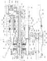
図1、2において、1は前後4輪駆動型のトラクタの動力伝達装置であり、エンジンEの後端側に連結されたフライホイールハウジングFの後端側にミッションケースMが連結されており、このミッションケースMは前後ミッションケースMF、MRを有し、それらの内部にトランスミッションTが収納されている。前記エンジンE、フライホイールハウジングF、ミッションケースM等によってトラクタの車体が構成されている。
Hereinafter, embodiments of the present invention will be described with reference to the drawings.
1 and 2, reference numeral 1 denotes a power transmission device for a front and rear four-wheel drive tractor. A transmission case M is connected to a rear end side of a flywheel housing F connected to a rear end side of the engine E. The transmission case M has front and rear transmission cases MF and MR, and a transmission T is accommodated therein. The engine E, flywheel housing F, transmission case M, etc. constitute a tractor body.
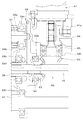
前記トランスミッションTは、エンジンEからの動力をフライホイール4及び緩衝機構5を介して推進軸6に伝達し、この推進軸6から4輪の前後駆動輪に伝達する走行駆動系と、推進軸6からPTO軸7に伝達するPTO駆動系とを有する。
このトランスミッションTの走行駆動系は、推進軸6の動力を正転で取り出す態様と逆転で取り出す態様とに変換する油圧切換式の前後進切換機構(シャトル装置)8と、前後進切換後の動力を4段変速する手動切換式の主変速機構9と、この主変速機構9で変速された動力を高低変速する手動切換式の副変速機構10と、高低切換後の動力を後輪(駆動輪)へ伝達する後輪デフ機構11と、前記副変速機構10による高低切換後の動力を前輪(駆動輪)へ伝達する前輪駆動系の前輪動力取出機構12とを備えている。
The transmission T transmits power from the engine E to the
The traveling drive system of the transmission T includes a hydraulically switched forward / reverse switching mechanism (shuttle device) 8 for converting the power of the
トランスミッションTのPTO駆動系は、前記推進軸6の後部にPTO駆動軸16が同軸心状に直結され、このPTO駆動軸16の後方に同軸心状に設けられたPTO伝動軸17と、PTO駆動軸16からPTO伝動軸17に動力を断接自在に伝達するPTOクラッチ18と、PTO伝動軸17からの動力を減速してPTO軸7に伝達する減速機構19とを備えている。
In the PTO drive system of the transmission T, a
前記前ミッションケースMFは前後に間隔をおいて第1支持壁Maと第2支持壁Mbとを有し、第1支持壁Maはフライホイール4及び緩衝機構5を収納したフライホイールハウジングF内と連通する第1室20と、前後進切換機構8が収納された第2室21とを区画しており、第2支持壁Mbは主変速機構9及び副変速機構10を収納した第3室22を前記第2室21と区画している。
The front mission case MF includes a first support wall Ma and a second support wall Mb spaced apart from each other in the front-rear direction. The first support wall Ma is disposed inside the flywheel housing F in which the flywheel 4 and the buffer mechanism 5 are housed. The
前記後ミッションケースMRは前後に間隔をおいて第3支持壁Mcと第4支持壁Mdとを有し、第3支持壁McはPTOクラッチ18を収納しかつ第3室22内と連通する第4室23とその後方の第5室24とを区画しており、第4支持壁Mdは第5室24と後輪デフ機構11を収納した第6室25とを区画している。
また、第1支持壁Maには中央に大きい開口Ma1が形成されていて、この開口Ma1を塞ぐように前軸支持ホルダ27がボルト等の固定具を介して取り付けられ、第3室22と第4室23との間にはそれらを前後に仕切るように後軸支持ホルダ28がボルト等の固定具を介して取り付けられている。この後軸支持ホルダ28は前ミッションケースMFの内周面に形成された突起に受持されかつボルト固定されている。
The rear transmission case MR has a third support wall Mc and a fourth support wall Md spaced apart from each other in the front-rear direction. The third support wall Mc houses the
The first support wall Ma has a large opening Ma1 formed at the center, and a front
前記推進軸6は、その前端が緩衝機構5と連結され、前部が前軸支持ホルダ27に支持され、後部が第2支持壁Mbに回転自在に支持されている。推進軸6と平行に後進伝動軸29が配置されており、この後進伝動軸29も推進軸6と同様に前後部が前軸支持ホルダ27と第2支持壁Mbとに回転自在に支持され、推進軸6と後進伝動軸29との間に油圧切換式の前後進切換機構8が配置されている。
The
油圧切換式前後進切換機構8は、推進軸6上に設けられた前進油圧クラッチ30と、この前進油圧クラッチ30の後側において推進軸6上に相対回転自在に支持された前進出力
ギヤ31と、後進油圧クラッチ32と、この後進油圧クラッチ32の前側において推進軸6上に相対回転自在に支持された後進出力ギヤ33と、後進伝動軸29の前部に一体回転自在に設けられた後進第1伝動ギヤ34と、後進伝動軸29の後部に一体回転自在に設けられた後進第2伝動ギヤ35とを備えている。
The hydraulic switching type forward /
前進出力ギヤ31と後進第2伝動ギヤ35とはともに、主変速機構9に動力を入力する入力ギヤ36に噛合しており、後進第1伝動ギヤ34は後進出力ギヤ33に噛合している。
前記前後進切換機構8は、前進油圧クラッチ30を作動することにより、推進軸6の正転動力を入力ギヤ36に伝達し、後進油圧クラッチ32を作動することにより、後進出力ギヤ33、後進第1伝動ギヤ34、後進伝動軸29及び後進第2伝動ギヤ35を介して推進軸6の正転動力を逆転して入力ギヤ36に伝達する。
Both the
The forward /
この前後進切換機構8は、前進油圧クラッチ30と後進油圧クラッチ32の両方を切ることにより、エンジンEから走行駆動系に伝達される動力を断接できるので、走行系メイン油圧クラッチの役目もしている。
図1〜5において、手動切換式の主変速機構9は、前記入力ギヤ36を有して前後進切換機構8から動力が入力される入力軸37と、この入力軸37と平行なカウンタ軸38との間に設けられている。カウンタ軸38は筒軸で前記PTO駆動軸16に外嵌しており、このカウンタ軸38と入力軸37とはともに、前部が第2支持壁Mbに、後部が後軸支持ホルダ28にそれぞれ回転自在に支持されている。
The forward /
1 to 5, a manually-switchable main transmission mechanism 9 includes an
入力軸37は前部が第2支持壁Mbから前方へ突出され、その突出前部に入力ギヤ36が装着され、第2支持壁Mbと後軸支持ホルダ28との間に、後方から順に主変速の第1速から第4速の駆動ギヤ39a〜42aが遊嵌されている。
前記第1速駆動ギヤ39aと第2速駆動ギヤ40aとは第1クラッチ手段43によって択一的に入力軸37と一体回転され、第3速駆動ギヤ41aと第4速駆動ギヤ42aとは第2クラッチ手段44によって択一的に入力軸37と一体回転される。
The front part of the
The first
カウンタ軸38には第1速から第4速の従動ギヤ39b〜42bが一体回転自在に設けられ、各従動ギヤ39b〜42bは前記入力軸37上の第1速から第4速の駆動ギヤ39a〜42aとそれぞれ噛合している。
カウンタ軸38上の第1〜4速従動ギヤ39b〜42bは、前方から後方へ高速側から低速側に順次配置され、従って、後側から前方に行くに従ってギヤ径が次第に小さくなっており、最前端の第4速従動ギヤ42bは最小径である。
The
The first to fourth speed driven
前記第1クラッチ手段43と第2クラッチ手段44とはシンクロメッシュ式になっていて、1本の変速レバーによって択一的に手動操作され、主変速機構9を中立状態から第1速ないし第4速のいずれかに変速操作できる。
カウンタ軸38の最小径の第4速従動ギヤ42b(最高速従動ギヤ)の前方部分には、副変速機構10用の低速駆動ギヤ46が形成され、副変速機構10用の高速駆動ギヤは前記第3速従動ギヤ41b(次高速従動ギヤ)が兼務している。
The first clutch means 43 and the second clutch means 44 are of a synchromesh type, and are alternatively manually operated by one shift lever, and the main transmission mechanism 9 is moved from the neutral state to the first to fourth speeds. The speed can be changed to either speed.
A low-
副変速機構10はカウンタ軸38とこれに平行に配置された出力軸47との間に設けられており、出力軸47上に、低速駆動ギヤ46と噛合する低速従動ギヤ48と、第3速従動ギヤ41bと噛合する高速従動ギヤ49とが遊嵌され、低速従動ギヤ48と高速従動ギヤ49とは第3クラッチ手段50によって択一的に出力軸47と一体回転可能に結合される。
The
前記第3速従動ギヤ41b及び第4速従動ギヤ42bは、主変速機構9の他の従動ギヤ39b、40bと比べて径が小さいので、低速従動ギヤ48及び高速従動ギヤ49はこれらの従動ギヤ41b、42bと軸方向にオーバラップして配置することが可能になっている。
即ち、低速従動ギヤ48及び高速従動ギヤ49の前後位置及び前後長さは、低速駆動ギヤ46、第3速従動ギヤ41b及び第4速従動ギヤ42bの前後位置及び前後長さと略同一になっており、第4速従動ギヤ42bが最小径であるので、出力軸47上に第3クラッチ手段50を配置しても干渉しないようになっている。逆に、低速駆動ギヤ46と第3速
従動ギヤ41bとの間に、第3クラッチ手段50に対応して第4速従動ギヤ42bを配置することができる。
Since the third speed driven
That is, the front and rear positions and front and rear lengths of the low speed driven
低速駆動ギヤ46を第4速従動ギヤ42bの前側に設けることにより、大径の低速従動ギヤ48を他の従動ギヤ39b、40bと干渉することなく、また周囲に無駄なスペースを作ることなく配置することが可能になっている。
前記出力軸47は第2支持壁Mbと後軸支持ホルダ28とに支持され、後端がベベルピニオン51と連結され、後輪デフ機構11に後輪動力を伝達する。
By providing the low-
The
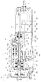
また、出力軸47の前端には低速従動ギヤ48の前側に隣接して前輪動力取出ギヤ53が装着され、この前輪動力取出ギヤ53は下方の伝動ギヤ54と噛合し、前輪動力取出手段52を構成している。
前記前輪動力取出手段52は、出力軸47の前部と前輪動力取出軸55の後部との間に設けられており、前記伝動ギヤ54は前輪動力取出軸55に遊嵌され、前輪駆動クラッチ手段56によって遊転と結合とが選択され、結合されることにより、出力軸47の動力は、前輪動力取出ギヤ53、伝動ギヤ54及び前輪動力取出軸55を介して、前輪動力として前輪デフ機構へ伝達される。
A front wheel power take-
The front wheel power take-out means 52 is provided between the front portion of the
前輪動力取出軸55は前後中途部が第1支持壁Maに貫通支持し、伝動ギヤ54を支持している後端が伝動ギヤ54の後側で第2支持壁Mbに支持し、それぞれ回転自在に支持されている。
図1、5において、前記出力軸47は入力軸37及びカウンタ軸38に対して平行状に配置され、かつそれらと三角配置されている。推進軸6及びPTO駆動軸16はエンジンEのクランク軸と同心であり、それらと前輪動力取出軸55とは、ミッションケースMの左右方向中央に位置し、出力軸47は左右一方(右側)に僅かにずれ、入力軸37はさらに大きく左右一方(右側)にずれて配置されている。
The front wheel power take-out
1 and 5, the
前記第2支持壁Mbは上下壁部Mb1、Mb2に上下分離形成されており、上部壁部Mb1は推進軸6及び後進伝動軸29の後端と、出力軸47、カウンタ軸38及び入力軸37の前端とを支持しており、下部壁部Mb2は前輪動力取出軸55を支持している。
上部壁部Mb1と下部壁部Mb2とは、それらの間に前輪動力取出ギヤ53及び伝動ギヤ54を配置するために前後に分離しており、従って、上部壁部Mb1と下部壁部Mb2との間には上下方向及び前後方向に開放した開口57が形成されている。
The second support wall Mb is vertically separated into upper and lower wall parts Mb1 and Mb2, and the upper wall part Mb1 has a rear end of the
The upper wall portion Mb1 and the lower wall portion Mb2 are separated from each other in order to dispose the front wheel power take-
この開口57は下部壁部Mb2が上部壁部Mb1の直下に位置する場合よりも前後に離れている分だけ大面積になっている。
ミッションケースM内は、第1室20以外は、第2室21から第6室25までオイルバスになっていて、トランスミッションTのための油及び油圧アクチュエータのためのミッション油が貯められている。
The
In the transmission case M, except for the
前記下部壁部Mb2、第3支持壁Mc、第4支持壁Md等はミッションケースMの底部との間にそれぞれ通路58が形成され、第2室21から第6室25までのミッション油の流通路になっている。
また、上部壁部Mb1は前輪動力取出ギヤ53より前側で出力軸47の前端を支持しているので、出力軸47の低速従動ギヤ48、高速従動ギヤ49及び前輪動力取出ギヤ53を配置している部分の前後部は、上部壁部Mb1と後軸支持ホルダ28とによって両持ち支持されている。
The lower wall Mb2, the third support wall Mc, the fourth support wall Md, and the like are each formed with a
Since the upper wall portion Mb1 supports the front end of the
下部壁部Mb2は低速従動ギヤ48の下方、前後方向直下に位置し、大径の低速従動ギヤ48の配置を可能にしており、低速従動ギヤ48と前輪動力取出ギヤ53との密接した隣接配置を可能にしている。
さらに、前輪動力取出ギヤ53を出力軸47の前端に配置可能にすることにより、前ミッションケースMF内における伝動ギヤ54の前後位置が可及的に前方となり、前輪動力取出軸55が出力軸47と前後方向にオーバラップする長さが短くなり、前輪動力取出軸55を短くかつ安価に形成できる。
The lower wall portion Mb2 is located below the low-speed driven
Further, by allowing the front wheel power take-
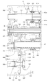
図1、5において、前ミッションケースMFの後端は大きく開放されており、その後部近傍の内周面に複数(4箇所)の突起59が設けられ、この突起59に前記後軸支持ホル
ダ28の外周部が受持されて、ボルト等の締結具で装着されている。
図1、2、4、5において、後軸支持ホルダ28の正面側には、入力軸37を軸受を介して支持する軸受凹部28aと、カウンタ軸38を軸受を介して支持する軸受凹部28bと、出力軸47を軸受を介して支持する軸受凹部28cとが形成され、背面側にはポンプ動力取出手段60が備えられ、内部には潤滑油路28dが形成されている。
1 and 5, the rear end of the front mission case MF is largely open, and a plurality (four places) of
1, 2, 4 and 5, on the front side of the rear
前ミッションケースMFの後端近傍の側壁外面にはトラクタの油圧機器へ作動油を供給する油圧ポンプ61が装着されており、前記ポンプ動力取出手段60を介してPTO駆動軸16から動力を取り出している。
前記ポンプ動力取出手段60は、PTO駆動軸16に嵌合装着された伝動ベベルギヤ62と、この伝動ベベルギヤ62に噛合している取出ベベルピニオン63とを有し、取出ベベルピニオン63と油圧ポンプ61のポンプ軸61aとはカップリング66を介して着脱自在に連結されている。前記取出ベベルピニオン63は軸部とベベルギヤとが一体成形されているが、別個に形成して固着したものでもよい。
A
The pump power take-out means 60 has a
後軸支持ホルダ28は背面側に、伝動ベベルギヤ62を軸受64を介して支持するギヤ保持部28eと、後方突出していて取出ベベルピニオン63を軸受65を介して支持するピニオン保持部28fとが形成されており、前記ギヤ保持部28eとピニオン保持部28fとは軸線が直交されている。
従って、前記後軸支持ホルダ28は、正面側から軸受凹部28a、28b及び28cが加工され、背面側にギヤ保持部28eが加工され、外側方から潤滑油路28d及びピニオン保持部28fが加工されており、これらは1物体に加工されているので、芯出しが正確にでき、また、伝動ベベルギヤ62と取出ベベルピニオン63との噛み合わせ調整も簡単かつ正確にできる。
The rear
Accordingly, in the rear
前記後軸支持ホルダ28のピニオン保持部28fの後端及び油圧ポンプ61の取付部61bの後端は、前ミッションケースMFの後端の後ミッションケースMR合わせ面70より前側に位置させており、前後ミッションケースMF、MRにそれぞれ構造物を組み込んでから合わせる際に、合わせ面70から突出する構造物を少なくして、組立てを容易にしている。
The rear end of the
後軸支持ホルダ28は前ミッションケースMFの後端から挿入して前ミッションケースMF内面の突起59に取り付け、伝動ベベルギヤ62と取出ベベルピニオン63とを組み込んだ後に、油圧ポンプ61を前ミッションケースMFの外方から組み付けることができる。
なお、本発明は前記実施形態における各部材の形状及びそれぞれの前後・左右・上下の位置関係は、図1〜5に示すように構成することが最良である。しかし、前記実施形態に限定されるものではなく、部材、構成を種々変形したり、組み合わせを変更したりすることもできる。
The rear
In the present invention, the shape of each member and the positional relationship between the front, back, left, and right in the above embodiment are best configured as shown in FIGS. However, it is not limited to the said embodiment, A member, a structure can be variously deformed, and a combination can also be changed.
例えば、走行系の変速機構は油圧切換式前後進切換機構8、主変速機構9及び副変速機構10としているが、前後進切換機構8は手動切換式であってもよく、前後進切換機構8の代わりに推進軸6の動力を高低切り換える油圧切換式又は手動切換式の高低切換機構であってもよい。
主変速機構9及び副変速機構10は油圧切換式であってもよく、副変速機構10を備えていなくてもよく、逆に、主変速機構9及び副変速機構10にさらに減速する超減速機構を追加してもよい。
For example, the traveling transmission mechanism is a hydraulic switching type forward /
The main transmission mechanism 9 and the
また、第2室21を前後に長く形成して、その内部に前後進切換機構8、主変速機構9及び副変速機構10等の複数の走行系の変速機構を配置し、この第2室21の後部を仕切る第2支持壁Mbに前輪動力取出軸55の後端を支持し、この前輪動力取出軸55が前記複数の走行系変速機構の前後方向略全長に亘ってそれらの下方に位置するものであってもよい。
Further, the
1 動力取出装置
6 推進軸
8 前後進切換機構
9 主変速機構
10 副変速機構
11 後輪デフ機構
12 前輪動力取出機構
16 駆動軸
20 第1室
21 第2室
22 第3室
27 前軸支持ホルダ
28 後軸支持ホルダ
29 後進伝動軸
36 入力ギヤ
37 入力軸
38 カウンタ軸
47 出力軸
48 副低速従動ギヤ
49 副高速従動ギヤ
52 前輪動力取出手段
53 前輪動力取出ギヤ
54 伝動ギヤ
55 前輪動力取出軸
56 前輪駆動クラッチ手段
57 開口
E エンジン
F フライホイールハウジング
M ミッションケース
MF 前ミッションケース
MR 後ミッションケース
Ma 第1支持壁
Mb 第2支持壁
Mb1 上部壁部
Mb2 下部壁部
T トランスミッション
DESCRIPTION OF SYMBOLS 1 Power take-out
Claims (2)
前記第2室(21)に推進軸(6)の動力を前後進に変速する前後進切換機構(8)を配置し、第3室(22)に前後進切換機構(8)から入力軸(37)に伝達される動力を多段変速してカウンタ軸(38)に伝達する主変速機構(9)、この主変速機構(9)で
変速された動力をカウンタ軸(38)から伝達して高低変速する副変速機構(10)及びこの副変速機構(10)から後輪動力を伝達する出力軸(47)を配置し、この出力軸(47)の動力を前輪動力取出手段(52)を介して前輪動力を取り出す前輪動力取出軸(55)を第1・第2支持壁(Ma・Mb)に支持したトラクタの動力伝達装置であって、
前記第2支持壁(Mb)を、前後進切換機構(8)の推進軸(6)、主変速機構(9)の入力軸(37)、副変速機構(10)のカウンタ軸(38)及び出力軸(47)をそれぞれ回転自在に支持する上部壁部(Mb1)と、この上部壁部(Mb1)から後下方に離れていて前輪動力取出軸(55)を支持する下部壁部(Mb2)とに上下前後分離形成して、上部壁部(Mb1)と下部壁部(Mb2)との間に上下方向及び前後方向に開放した開口(57)を形成し、この開口(57)に前記前輪動力取出手段(52)を配置しており、
前記前輪動力取出手段(52)は、上部壁部(Mb1)の後側で出力軸(47)の前端に配置された前輪動力取出ギヤ(53)と、この前輪動力取出ギヤ(53)と噛合していて前輪動力取出軸(55)の後端に支持された伝動ギヤ(54)とを有し、
前記出力軸(47)の前端に前輪動力取出ギヤ(53)と隣接して配置される副変速機構(10)の副低速従動ギヤ(48)を下部壁部(Mb2)の上方に配置し、伝動ギヤ(54)を前輪動力取出軸(55)に結合する前輪駆動クラッチ手段(56)を上部壁部(Mb1)の下方に配置していることを特徴とするトラクタの動力伝達装置。 First and second support walls (Ma, Mb) are provided in the front transmission case (MF) connected to the flywheel housing (F) to communicate with the flywheel housing (F). ), An intermediate second chamber (21) and a rear third chamber (22), and the second chamber (21) and the third chamber (22) are oil baths,
A forward / reverse switching mechanism (8) for shifting the power of the propulsion shaft (6) forward and backward is disposed in the second chamber (21), and an input shaft (from the forward / reverse switching mechanism (8) to the third chamber (22). 37) a main transmission mechanism (9) that multi-shifts the power transmitted to 37) and transmits it to the countershaft (38), and transmits the power shifted by this main transmission mechanism (9) from the countershaft (38). A sub-transmission mechanism (10) for shifting gears and an output shaft (47) for transmitting rear wheel power from the sub-transmission mechanism (10) are arranged, and the power of the output shaft (47) is transmitted via the front wheel power take-out means (52). A power transmission device for a tractor in which a front wheel power take-off shaft (55) for taking out front wheel power is supported by first and second support walls (Ma, Mb),
The second support wall (Mb) is connected to the propulsion shaft (6) of the forward / reverse switching mechanism (8), the input shaft (37) of the main transmission mechanism (9), the counter shaft (38) of the auxiliary transmission mechanism (10), and An upper wall portion (Mb1) that rotatably supports the output shaft (47), and a lower wall portion (Mb2) that is separated rearward and downward from the upper wall portion (Mb1) and supports the front wheel power take-off shaft (55). And an opening (57) opened in the vertical direction and the front-rear direction is formed between the upper wall portion (Mb1) and the lower wall portion (Mb2), and the front wheel is formed in the opening (57). Power take-out means (52) is arranged,
The front wheel power take-out means (52) meshes with the front wheel power take-out gear (53) disposed at the front end of the output shaft (47) on the rear side of the upper wall portion (Mb1), and the front wheel power take-out gear (53). possess a supported transmission gear (54) to the rear end of the front wheel power take-axis (55) and has,
An auxiliary low-speed driven gear (48) of the auxiliary transmission mechanism (10) arranged adjacent to the front wheel power take-off gear (53) at the front end of the output shaft (47) is arranged above the lower wall portion (Mb2); power transmission device of a tractor, characterized that you have placed below the upper wall portion of the front wheel drive clutch means (56) for coupling to a transmission gear (54) front power take-axis (55) (Mb1).
前記下部壁部(Mb2)は前ミッションケース(MF)の底部との間に、第2室(21)と第3室(22)とを連通する油の通路(58)を形成していることを特徴とする請求項1に記載のトラクタの動力伝達装置。 In the front wheel power take-out means (52), the front wheel power take-out gear (53) projects downward from the upper wall portion (Mb1) in the opening (57), and the transmission gear (54) falls in the lower wall portion in the opening (57). Projecting upward from (Mb2),
The lower wall portion (Mb2) forms an oil passage (58) communicating with the second chamber (21) and the third chamber (22) between the bottom portion of the front mission case (MF). The power transmission device for a tractor according to claim 1.
Priority Applications (7)
| Application Number | Priority Date | Filing Date | Title |
|---|---|---|---|
| JP2010217484A JP4916570B1 (en) | 2010-09-28 | 2010-09-28 | Power transmission device for tractor |
| CN201410122755.9A CN103867690B (en) | 2010-09-28 | 2011-09-26 | The transmission mechanism of tractor |
| CN201110287649.2A CN102418775B (en) | 2010-09-28 | 2011-09-26 | Tractor transmission device |
| US13/825,742 US9032822B2 (en) | 2010-09-28 | 2011-09-27 | Power transmission device of tractor |
| PCT/JP2011/072076 WO2012043561A1 (en) | 2010-09-28 | 2011-09-27 | Power transmission device of tractor |
| EP11829114.5A EP2623355B1 (en) | 2010-09-28 | 2011-09-27 | Power transmission device of tractor |
| EP18200050.5A EP3450800B1 (en) | 2010-09-28 | 2011-09-27 | Power transmission device of tractor |
Applications Claiming Priority (1)
| Application Number | Priority Date | Filing Date | Title |
|---|---|---|---|
| JP2010217484A JP4916570B1 (en) | 2010-09-28 | 2010-09-28 | Power transmission device for tractor |
Publications (2)
| Publication Number | Publication Date |
|---|---|
| JP4916570B1 true JP4916570B1 (en) | 2012-04-11 |
| JP2012071670A JP2012071670A (en) | 2012-04-12 |
Family
ID=45943339
Family Applications (1)
| Application Number | Title | Priority Date | Filing Date |
|---|---|---|---|
| JP2010217484A Active JP4916570B1 (en) | 2010-09-28 | 2010-09-28 | Power transmission device for tractor |
Country Status (2)
| Country | Link |
|---|---|
| JP (1) | JP4916570B1 (en) |
| CN (2) | CN102418775B (en) |
Cited By (2)
| Publication number | Priority date | Publication date | Assignee | Title |
|---|---|---|---|---|
| CN108223703A (en) * | 2016-12-09 | 2018-06-29 | 辽宁丹东新弘源农业科技发展有限公司企业技术研究开发中心 | Vapour drags all-in-one machine combined type speed change transfer case |
| CN108488344A (en) * | 2018-04-29 | 2018-09-04 | 郑宇虎 | A kind of multi-faceted power output positive and negative rotation power transmission box |
Families Citing this family (3)
| Publication number | Priority date | Publication date | Assignee | Title |
|---|---|---|---|---|
| CN104919925A (en) * | 2014-03-17 | 2015-09-23 | 张小霞 | Multifunctional walking tractor chassis |
| US10066730B2 (en) * | 2014-09-29 | 2018-09-04 | Aichi Machine Industry, Co., Ltd. | Gearbox and method for assembling same |
| US9964182B2 (en) | 2014-11-20 | 2018-05-08 | GM Global Technology Operations LLC | Multi-stage transmission |
Family Cites Families (9)
| Publication number | Priority date | Publication date | Assignee | Title |
|---|---|---|---|---|
| JPH05280615A (en) * | 1992-04-03 | 1993-10-26 | Kubota Corp | Mission structure for working vehicle |
| JP2003074648A (en) * | 2001-09-04 | 2003-03-12 | Kanzaki Kokyukoki Mfg Co Ltd | Hydraulic clutch |
| JP4368283B2 (en) * | 2004-09-28 | 2009-11-18 | 株式会社クボタ | Traveling vehicle |
| JP4390744B2 (en) * | 2005-04-27 | 2009-12-24 | 株式会社クボタ | Power transmission device for tractor |
| JP2006335248A (en) * | 2005-06-02 | 2006-12-14 | Kubota Corp | Power transmission for tractor |
| JP2007145217A (en) * | 2005-11-29 | 2007-06-14 | Kanzaki Kokyukoki Mfg Co Ltd | Travelling system auxiliary transmission |
| JP4765800B2 (en) * | 2006-07-10 | 2011-09-07 | マツダ株式会社 | transmission |
| JP4616321B2 (en) * | 2007-10-18 | 2011-01-19 | 株式会社クボタ | Transmission device for traveling vehicle |
| JP5006778B2 (en) * | 2007-12-28 | 2012-08-22 | 株式会社クボタ | Power transmission device for tractor |
-
2010
- 2010-09-28 JP JP2010217484A patent/JP4916570B1/en active Active
-
2011
- 2011-09-26 CN CN201110287649.2A patent/CN102418775B/en active Active
- 2011-09-26 CN CN201410122755.9A patent/CN103867690B/en active Active
Cited By (4)
| Publication number | Priority date | Publication date | Assignee | Title |
|---|---|---|---|---|
| CN108223703A (en) * | 2016-12-09 | 2018-06-29 | 辽宁丹东新弘源农业科技发展有限公司企业技术研究开发中心 | Vapour drags all-in-one machine combined type speed change transfer case |
| CN108223703B (en) * | 2016-12-09 | 2023-09-12 | 周明和 | Combined type speed change transfer case for steam-driven integrated machine |
| CN108488344A (en) * | 2018-04-29 | 2018-09-04 | 郑宇虎 | A kind of multi-faceted power output positive and negative rotation power transmission box |
| CN108488344B (en) * | 2018-04-29 | 2023-10-27 | 郑宇虎 | Multidirectional power output positive and negative power transmission case |
Also Published As
| Publication number | Publication date |
|---|---|
| CN102418775A (en) | 2012-04-18 |
| CN103867690A (en) | 2014-06-18 |
| CN102418775B (en) | 2014-08-27 |
| JP2012071670A (en) | 2012-04-12 |
| CN103867690B (en) | 2016-06-08 |
Similar Documents
| Publication | Publication Date | Title |
|---|---|---|
| KR100985673B1 (en) | Speed change device of traveling vehicle | |
| JP4916570B1 (en) | Power transmission device for tractor | |
| JP2008298223A (en) | Transmission | |
| WO2012043561A1 (en) | Power transmission device of tractor | |
| KR20150137379A (en) | Transmission assembly of an agriculture vehicle | |
| JP4809493B1 (en) | Power transmission device for tractor | |
| JP4809492B1 (en) | Power transmission device for tractor | |
| JP5006778B2 (en) | Power transmission device for tractor | |
| JP5821335B2 (en) | Travel transmission for work vehicle | |
| JP2009036227A (en) | Transmission | |
| JP2018189197A (en) | Power transmission device for vehicle | |
| JP4302603B2 (en) | Tractor transmission | |
| KR20150145041A (en) | Transmission assembly of an agriculture vehicle | |
| JP6097463B2 (en) | Driving force transmission structure for vehicles | |
| JP3505776B2 (en) | transmission | |
| JP5094104B2 (en) | Power transmission device for tractor | |
| JP4860449B2 (en) | Hydraulic pipeline structure | |
| JP2012001146A (en) | Tractor | |
| JP3483706B2 (en) | Tractor mission | |
| KR102350386B1 (en) | Transmission of agriculture vehicle | |
| JP3474705B2 (en) | Tractor mission | |
| JP5838618B2 (en) | Travel transmission for work vehicle | |
| JP2008030688A (en) | Transmission gear of agricultural tractor | |
| JP2018189196A (en) | Power transmission device for vehicle | |
| JPS5835885B2 (en) | tractor |
Legal Events
| Date | Code | Title | Description |
|---|---|---|---|
| TRDD | Decision of grant or rejection written | ||
| A01 | Written decision to grant a patent or to grant a registration (utility model) |
Free format text: JAPANESE INTERMEDIATE CODE: A01 Effective date: 20120124 |
|
| A01 | Written decision to grant a patent or to grant a registration (utility model) |
Free format text: JAPANESE INTERMEDIATE CODE: A01 |
|
| A61 | First payment of annual fees (during grant procedure) |
Free format text: JAPANESE INTERMEDIATE CODE: A61 Effective date: 20120124 |
|
| FPAY | Renewal fee payment (event date is renewal date of database) |
Free format text: PAYMENT UNTIL: 20150203 Year of fee payment: 3 |
|
| R150 | Certificate of patent or registration of utility model |
Ref document number: 4916570 Country of ref document: JP Free format text: JAPANESE INTERMEDIATE CODE: R150 Free format text: JAPANESE INTERMEDIATE CODE: R150 |