JP4909308B2 - Image processing method and apparatus - Google Patents
Image processing method and apparatus Download PDFInfo
- Publication number
- JP4909308B2 JP4909308B2 JP2008079195A JP2008079195A JP4909308B2 JP 4909308 B2 JP4909308 B2 JP 4909308B2 JP 2008079195 A JP2008079195 A JP 2008079195A JP 2008079195 A JP2008079195 A JP 2008079195A JP 4909308 B2 JP4909308 B2 JP 4909308B2
- Authority
- JP
- Japan
- Prior art keywords
- image
- color
- point
- brightness
- image processing
- Prior art date
- Legal status (The legal status is an assumption and is not a legal conclusion. Google has not performed a legal analysis and makes no representation as to the accuracy of the status listed.)
- Expired - Fee Related
Links
Images


Description
本発明は、原画像に対して画像補正を行う画像処理方法及び装置及び記憶媒体に関するものである。 The present invention relates to an image processing method and apparatus for performing image correction on an original image, and a storage medium.
従来、写真画像の色バランスを調整する方法としては、(1):撮る前に色バランスを合わせる方法と、(2):撮った後の画像を修正する方法という2通りの方法がある。方法(1)の例としては、例えばビデオカメラのホワイトバランススイッチを用いた色バランスの調整がある。この方法では、本撮影を開始する前に白い紙などを予備的に撮影し、撮影された画像の白の色バランスを調整する。 Conventionally, there are two methods for adjusting the color balance of a photographic image: (1): adjusting the color balance before taking a picture, and (2): correcting the image after taking a picture. As an example of the method (1), there is, for example, color balance adjustment using a white balance switch of a video camera. In this method, white paper or the like is preliminarily photographed before the actual photographing is started, and the white color balance of the photographed image is adjusted.
方法(2)は印刷の分野などで広く行われているが、その多くは職人の勘と経験によるところが多い。 Method (2) is widely used in the field of printing, etc., but most of it depends on the intuition and experience of craftsmen.
一方、近年とくにデジタルカメラやフォトスキャナが普及したことに伴って、フォト画像のデジタル化が一般の人にも手軽に行えるようになってきた。また、インクジェットプリンタを代表とする出力機器側も高画質化、低価格化が進み、一般のユーザが自宅で写真を手軽に出力することも可能となっている。 On the other hand, with the recent spread of digital cameras and photo scanners in particular, digitization of photo images has become easy for ordinary people. In addition, output devices such as inkjet printers have also been improved in image quality and price, so that ordinary users can easily output photos at home.
しかしながら、デジタル化したフォト画像を印刷出力する場合、出力される画像の画質にはまだ問題が多い。 However, when printing a digitized photo image, there are still many problems with the image quality of the output image.
例えば、いわゆるパーソナルコンピュータ等を介して、入力機器側のRGB信号を、インクジェットプリンタを代表する出力機器でプリントする場合を考えると、例えばアップル社のマッキントッシュ(登録商標)におけるカラーシンクや、マイクロソフト社のWindows(登録商標)におけるCMSなどによって、CIEのXYZ色空間を介した入力機器側と出力機器側とのカラーマッチングが試みられている。しかし、これらの調整を厳密に行うことは非常に困難である。というのも、入力機器側と出力機器側では当然色再現範囲が異なり、さらに入力機器側はR,G,Bの発光信号で、出力機器側はC,M,Y,Kの反射原稿であるという原理的な違いもあるためである。 For example, when the RGB signal on the input device side is printed by an output device typified by an ink jet printer via a so-called personal computer or the like, for example, the color sync in the Macintosh (registered trademark) of Apple Inc., the Microsoft Inc. Color matching between the input device side and the output device side through the CIE XYZ color space has been attempted by CMS or the like in Windows (registered trademark). However, it is very difficult to make these adjustments strictly. This is because the color reproduction range is naturally different between the input device side and the output device side, and the input device side is a light emission signal of R, G, B, and the output device side is a reflection original of C, M, Y, K. This is because there is a fundamental difference.
このような困難を克服して入力機器と出力機器とのカラーマッチングがとれたとしても、そもそも入力機器側からの画像が満足のいくものでない場合には、その画像を厳密に印刷物として再現できたとしてもユーザが満足できる画像は得られない。これには、画像の露出のオーバーやアンダーという状態や、「色かぶり」という現象によって画像全体の色バランスがくるってしまうことが大きな原因と考えられる。 Even if the color matching between the input device and the output device was achieved by overcoming such difficulties, if the image from the input device was not satisfactory in the first place, the image could be reproduced exactly as a printed matter. However, an image that satisfies the user cannot be obtained. This is considered to be caused mainly by an overexposed or underexposed state of the image or a color balance of the entire image due to the phenomenon of “color cast”.
例えば、カメラでオート撮影するとAE(自動露出)がかかってしまうため、背景の大部分に青空が含まれているような場合、全体として暗くなってしまい、いわゆる露出アンダーの状態になり、逆に背景の大部分が暗い部分であれば露出オーバーの状態になって、肝心の被写体が必ずしもベストな状態で写らないことがある。 For example, since AE (automatic exposure) is applied when shooting automatically with a camera, if the background contains a large amount of blue sky, it becomes dark as a whole, resulting in a so-called underexposed state. If the background is mostly dark, it may be overexposed, and the important subject may not always be in the best condition.
また、デジタルカメラを例に取ると、画像はCCDカメラで撮影されるため、人間の目では感じられない波長の色も画像信号として入ってしまう。その信号をRGB信号の一部として処理すると、本来見えないはずの色が顕在化して色バランスが狂ってしまう。もちろん赤外カットフィルタなどの処理がなされるが必ずしも完全ではなく、色バランス補正に関してもリアルタイム処理という制約もあって、結果的に処理しきれずに「色かぶり」という現象が生じ、全体の色バランスがおかしくなる場合がある。 Taking a digital camera as an example, an image is taken by a CCD camera, and therefore, a color having a wavelength that cannot be sensed by human eyes also enters as an image signal. If the signal is processed as a part of the RGB signal, the color that should not be visible becomes obvious and the color balance is lost. Of course, processing such as an infrared cut filter is performed, but it is not always perfect, and color balance correction is also limited by real-time processing. As a result, it cannot be processed and a phenomenon called “color cast” occurs, resulting in an overall color balance. May go wrong.
フォトスキャナやフラットヘッドスキャナに関しても同様の現象が生じる可能性があるため、たとえネガやリバーサルフィルムでベストな状態であったとしても、これをデジタル化した際に色バランスが狂ってしまうこともあり得る。 The same phenomenon may occur with photo scanners and flat head scanners, so even if it is the best with negatives and reversal film, the color balance may be distorted when digitized. obtain.
このように、良好な出力結果を得るためには、入力画像データそのものを色バランスのとれた適正な露出の画像データに補正する必要があり、しかもそのためには、ユーザーの手を煩わせず、処理速度としても十分許容できる簡易的な方法が求められている。 As described above, in order to obtain a good output result, it is necessary to correct the input image data itself to image data with an appropriate exposure in which color balance is achieved, and for that purpose, it does not bother the user. There is a need for a simple method that is sufficiently acceptable in terms of processing speed.
本発明は上記従来例に鑑みてなされたもので、簡単な構成で原画像の色かぶりの補正を行うことができるようにすることを目的とする。 The present invention has been made in view of the above-described conventional example, and an object thereof is to enable correction of color cast of an original image with a simple configuration.
上記目的を達成するために本発明は以下の構成を有する。すなわち本発明は、デジタルカメラにより撮影された原画像から画素数を減らした画像を用いて、前記原画像のハイライトポイントおよびシャドーポイントを検出し、
前記ハイライトポイントおよびシャドーポイントの色みを求め、
前記ハイライトポイント、前記シャドーポイントおよび前記色みに基づき、前記ハイライトポイント、前記シャドーポイントを明るさと色みの空間における明るさを示す軸に向かい少なくとも回転させる行列を算出し、
前記原画像の各画素に、前記行列に従い色かぶり補正をすることを特徴とする画像処理方法にある。
In order to achieve the above object, the present invention has the following configuration. That is, the present invention detects a highlight point and a shadow point of the original image using an image obtained by reducing the number of pixels from the original image taken by the digital camera ,
Find the highlight point and shadow point color,
Based on the highlight point, the shadow point, and the color , calculate a matrix that at least rotates the highlight point, the shadow point toward an axis indicating brightness in brightness and color space ,
In the image processing method, color fog correction is performed on each pixel of the original image according to the matrix .
本発明によれば、簡単な構成で原画像の色かぶりの補正を行うことができる。 According to the present invention, it is possible to correct a color cast of an original image with a simple configuration.
以下、本発明の好適な実施形態について、添付図面を参照しながら詳細に説明する。 DESCRIPTION OF EXEMPLARY EMBODIMENTS Hereinafter, preferred embodiments of the invention will be described in detail with reference to the accompanying drawings.
[第1の実施の形態]
本実施の形態における画像処理方法では、RGBの原画像データを、画素ごとに明るさを示す輝度と色みを示す色度のデータに変換する。この時、原画像データの彩度が既定値を越えている場合にはその画素を間引きながら画素を順次選択し、輝度ヒストグラムを作成していく。そして高輝度側、低輝度側それぞれからの累積度数値が夫々所定の度数に達する輝度位置(輝度値)を白位置(ハイライトポイント)、黒位置(シャドーポイント)として求める。またこの時、白位置、黒位置検出の精度を向上するために、高彩度画素を輝度ヒストグラム作成に含めない処理などを行っても良い。
[First Embodiment]
In the image processing method according to the present embodiment, RGB original image data is converted into luminance data indicating brightness and chromaticity data indicating color for each pixel. At this time, if the saturation of the original image data exceeds a predetermined value, the pixels are sequentially selected while thinning out the pixels, and a luminance histogram is created. Then, the luminance positions (luminance values) at which the cumulative frequency values from the high luminance side and the low luminance side respectively reach predetermined frequencies are obtained as white positions (highlight points) and black positions (shadow points). At this time, in order to improve the accuracy of the white position and black position detection, a process of not including the high saturation pixel in the luminance histogram creation may be performed.
こうして白位置と判断された輝度値を有する画素データの色度の平均値と、黒位置と判断された輝度値を有する画素データの色度の平均値とを計算し、色空間上でそれら2点を結んだ直線を原画像の色立体軸(グレーライン)と判断する。その色立体軸の輝度軸に対する傾きは、本来輝度のみの変化であるべき色立体軸が、色度の変化を伴っていること、即ち色かぶりが生じていることを示している。この色立体軸が前記色空間上で正規の位置になるように、全画素に変換処理(回転行列演算)を施すことで色かぶりを補正する。以下、図面を参照して本実施形態を詳細に説明する。 Thus, the average value of the chromaticity of the pixel data having the luminance value determined as the white position and the average value of the chromaticity of the pixel data having the luminance value determined as the black position are calculated. A straight line connecting points is determined as the color solid axis (gray line) of the original image. The inclination of the color solid axis with respect to the luminance axis indicates that the color solid axis, which should be a change only in luminance, is accompanied by a change in chromaticity, that is, a color cast is generated. The color cast is corrected by performing conversion processing (rotation matrix calculation) on all the pixels so that the color solid axis is a normal position in the color space. Hereinafter, this embodiment will be described in detail with reference to the drawings.
<画像処理システムの構成>
本実施形態におけるシステムの一例を図1に示す。ホストコンピュータ100には、例えばインクジェットプリンタなどのプリンタ105とモニタ106が接続されている。ホストコンピュータ100は、ワードプロセッサ、表計算、インターネットブラウザ等のアプリケーションソフトウエア101と、OS(Operating System)102、アプリケーション101によってOS102に発行される出力画像を示す各種描画命令群(イメージ描画命令、テキスト描画命令、グラフィックス描画命令)を処理して印刷データを作成するプリンタドライバ103、およびアプリケーション101が発行する各種描画命令群を処理してモニタ106に表示を行なうモニタドライバ104をソフトウエアとして持つ。
<Configuration of image processing system>
An example of the system in this embodiment is shown in FIG. For example, a
ホストコンピュータ100は、これらソフトウエアが動作可能な各種ハードウエアとして中央演算処理装置CPU108、ハードディスクドライバHD107、ランダムアクセスメモリRAM109、リードオンリーメモリROM110等を備える。
The
図1で示される画像処理システムの例として、例えば一般的に普及しているIBM社製のPC−AT互換のパーソナルコンピュータにMicrosoft社のWindows(登録商標)95をOSとして使用し、印刷を行える所望のアプリケーションをインストールし、モニタとプリンタとを接続した形態が考えられる。 As an example of the image processing system shown in FIG. 1, for example, a Windows-registered trademark 95 of Microsoft Corporation can be used as an OS for a PC-AT compatible personal computer manufactured by IBM, which can be used for printing. A form in which a desired application is installed and a monitor and a printer are connected is conceivable.
ホストコンピュータ100では、モニタに表示された表示画像にもとづき、アプリケーション101で、文字などのテキストに分類されるテキストデータ、図形などのグラフィックスに分類されるグラフィックスデータ、自然画などに分類されるイメージ画像データなどを用いて出力画像データを作成する。そして、出力画像データを印刷出力するときには、アプリケーション101からOS102に印刷出力要求を行ない、グラフィックスデータ部分はグラフィックス描画命令、イメージ画像データ部分はイメージ描画命令で構成される出力画像を示す描画命令群をOS102に発行する。OS102はアプリケーションの出力要求を受け、出力プリンタに対応するプリンタドライバ103に描画命令群を発行する。プリンタドライバ103はOS102から入力した印刷要求と描画命令群を処理しプリンタ105で印刷可能な印刷データを作成してプリンタ105に転送する。プリンタ105がラスタープリンタである場合は、プリンタドライバ103では、OSからの描画命令に対して順次画像補正処理を行い、そして順次RGB24ビットページメモリにラスタライズし、全ての描画命令をラスタライズした後にRGB24ビットページメモリの内容をプリンタ105が印刷可能なデータ形式、例えばCMYKデータに変換を行ないプリンタに転送する。
In the
プリンタドライバ103で行われる処理を図2に用いて説明する。
Processing performed by the
プリンタドライバ103は、OS102から入力した描画命令群に含まれるイメージ描画命令の色情報に対して、画像補正処理部120で後述する画像補正処理を行う。プリンタ用補正処理部121は、まず、画像補正処理された色情報によって描画命令をラスタライズし、RGB24ビットページメモリ上にドット画像データを生成する。そして、各画素に対してプリンタの色再現性に応じたマスキング処理、ガンマ補正処理および量子化処理などを行い、プリンタ特性に依存したCMYKデータを生成してプリンタ105に転送する。
The
<画像補正処理部>
次に、イメージ描画命令で示される原画像に対して画像補正処理部120で行われる処理を図3〜図7,図9を用いて説明する。グラフィクス描画命令あるいはテキスト描画命令で示される原画像に対しては以下の処理は行われない。
<Image correction processing unit>
Next, processing performed by the image
本実施形態の画像補正処理部120は、図3に示したように、ヒストグラム作成処理(図3−S20)とヒストグラムに応じた画像補正処理(図3−S30)を行う。ステップS20では、図4に示すような処理によりヒストグラムを作成する。そして、作成されたヒストグラムに基づき画像のハイライトポイントおよびシャドーポイントを決定する。
As shown in FIG. 3, the image
(輝度ヒストグラムの作成)
図4は本実施形態での輝度ヒストグラムを作成するフローチャートである。
(Create brightness histogram)
FIG. 4 is a flowchart for creating a luminance histogram in the present embodiment.
図4において、S1で原画像の輝度ヒストグラム作成のルーチンに入ると、S2で原画像の画素から輝度ヒストグラムの作成に用いる画素の選択比率を決定する。本実施形態では、処理対象の画像データが35万画素の場合に全画素を対象(選択比率1(あるいは100%))に輝度ヒストグラムを作成することとする。35万画素以上の画素数の画像データが入力された場合には、その総画素数の35万画素に対する比率に応じて画素選択(サンプリング)を行う。例えば、350万画素の画像データが入力された場合には、選択比率は350万/35万=10であり、10画素に1画素の割合(選択比率10(あるいは10%))で輝度ヒストグラムを作成する。本実施形態では選択比率nは次式により求める。
n=int(対象画像データの総画素数/基準画素数35万)、(但し、n<1の時はn=1、nは正数)。
In FIG. 4, when the routine for creating the luminance histogram of the original image is entered in S1, the selection ratio of the pixels used for creating the luminance histogram is determined from the pixels of the original image in S2. In the present embodiment, when the image data to be processed is 350,000 pixels, a luminance histogram is created for all pixels (selection ratio 1 (or 100%)). When image data having 350,000 or more pixels is input, pixel selection (sampling) is performed according to the ratio of the total number of pixels to 350,000 pixels. For example, when image data of 3.5 million pixels is input, the selection ratio is 3.5 million / 350,000 = 10, and a luminance histogram is displayed at a ratio of one pixel to 10 pixels (selection ratio 10 (or 10%)). create. In this embodiment, the selection ratio n is obtained by the following equation.
n = int (total number of pixels of target image data / reference number of pixels 350,000) (however, when n <1, n = 1 and n is a positive number).
続いてS3でライン番号を管理するカウンタをリセットあるいは所定の初期値にセットし、S4でそのカウンタをインクリメントして注目ラインのライン番号とする。 Subsequently, in S3, the counter for managing the line number is reset or set to a predetermined initial value, and in S4, the counter is incremented to be the line number of the target line.
本実施形態では画素の間引き(サンプリング)はライン単位で行うので、選択比率nの場合には、ライン番号をnで割ったときの余りが0の場合に、そのラインに属する画素を処理対象として選択する(S5−YES)。例えば選択比率10の場合であれば、ライン番号を10で割ったときの余りが0の場合に、そのラインに属する画素を処理対象として選択する注目ラインが間引かれるライン、すなわち処理対象とならないラインの場合にはS4に戻る。処理対象ラインの場合にはS6に進み、注目ラインに属する画素に順次注目し、その注目画素に対して輝度変換,色度変換を処理を行う。本実施形態における輝度変換、色度変換は以下の式により行う。なお、輝度、色度変換は以下の式に限らず様々な式を用いることが可能である。
Y(輝度)=int(0.30R+0.59G+0.11B)(Yは正数)、
C1(色度)=R−Y、C2(色度)=B−Y。
In this embodiment, pixel thinning (sampling) is performed in units of lines. Therefore, in the case of a selection ratio n, if the remainder when the line number is divided by n is 0, pixels belonging to that line are processed. Select (S5-YES). For example, in the case of a selection ratio of 10, when the remainder when the line number is divided by 10 is 0, the line of interest for selecting the pixel belonging to that line as the processing target is thinned out, that is, it is not the processing target. In the case of a line, the process returns to S4. In the case of the processing target line, the process proceeds to S6, where attention is sequentially paid to pixels belonging to the target line, and luminance conversion and chromaticity conversion are performed on the target pixel. Luminance conversion and chromaticity conversion in this embodiment are performed by the following equations. The luminance and chromaticity conversion is not limited to the following formulas, and various formulas can be used.
Y (luminance) = int (0.30R + 0.59G + 0.11B) (Y is a positive number),
C1 (chromaticity) = RY, C2 (chromaticity) = BY.
また本実施形態では白位置(ハイライトポイント)、黒位置(シャドーポイント)の検出精度を向上させるために次式により注目画素の彩度Sを計算し、予め定めた彩度値(Sconst)より大きいか否かを判断して(S7)、大きい場合には、その画素の情報は輝度ヒストグラムに反映させない。
彩度S=sqrt(C1^2+C2^2)。
ここでsqrt(x)はxの平方根を与える関数であり、x^yはxのy乗を表す。
In this embodiment, in order to improve the detection accuracy of the white position (highlight point) and the black position (shadow point), the saturation S of the target pixel is calculated by the following equation, and the saturation value (Sconst) is determined in advance. It is determined whether or not the pixel is large (S7). If the pixel is large, the pixel information is not reflected in the luminance histogram.
Saturation S = sqrt (C1 ^ 2 + C2 ^ 2).
Here, sqrt (x) is a function that gives the square root of x, and x ^ y represents x to the power of y.
即ち、(S>Sconst)の場合にはS6に戻り、注目画素のデータは以後の処理に反映させない。これは、後述する通り、白位置の彩度は高輝度の画素群の平均彩度により与えられ、その彩度の値は色かぶりにより生じた誤差となるため、本来高彩度であると考えられる画素はハイライトポイントの算出から除外したほうが良いためである。この処理の効果を具体例を上げて説明する。例えばイエローの画素(R=G=255、B=0)は、上式からその輝度Yは226となり、彩度Sは227となる。すなわち、この画素は極めて高輝度であるとともに、十分に彩度の高い色を有することが分かる。このような画素は、無彩色の画素がイエローに色かぶりした結果そのようになったと判断するよりも、本来イエローの画素であると判断した方が多くの場合間違えが少ない。このような高輝度・高彩度の画素を輝度ヒストグラムに含めると、検出される白位置に誤差が生じてしまう。よって、本実施形態では所定の彩度(Sconst)を定め、所定の彩度を越える彩度の画素は輝度ヒストグラムに含めない。こうすることで、高彩度の画素により検出される白位置に誤差が生じることを防ぎ、白位置の精度を向上させることができる。 That is, if (S> Sconst), the process returns to S6, and the data of the pixel of interest is not reflected in the subsequent processing. This is because, as will be described later, the saturation at the white position is given by the average saturation of the high-luminance pixel group, and the value of the saturation is an error caused by the color cast. This is because it is better to exclude from highlight point calculation. The effect of this processing will be described with a specific example. For example, a yellow pixel (R = G = 255, B = 0) has a luminance Y of 226 and a saturation S of 227 from the above equation. That is, it can be seen that this pixel has extremely high luminance and has a sufficiently saturated color. Such a pixel is more likely to be mistaken in many cases if it is determined that it is originally a yellow pixel than it is determined that an achromatic pixel is colored yellow. If such high luminance and high saturation pixels are included in the luminance histogram, an error occurs in the detected white position. Therefore, in the present embodiment, a predetermined saturation (Sconst) is determined, and pixels having a saturation exceeding the predetermined saturation are not included in the luminance histogram. By doing so, it is possible to prevent an error from occurring in the white position detected by the high-saturation pixel and improve the accuracy of the white position.
このように、S7における判断の後、条件(S≦Sconst)を満たした画素について輝度ヒストグラムを作成していく(S8)。ここで本実施形態で扱う画素データRGBは各8ビット(256階調)データであるので、輝度Yも256の深さに変換される。よって輝度ヒストグラムは、0から255までの256段階の各輝度値の画素が夫々何度数あるかを計数することで得られる。 As described above, after the determination in S7, a luminance histogram is created for pixels that satisfy the condition (S ≦ Sconst) (S8). Here, since the pixel data RGB handled in the present embodiment is 8-bit (256 gradations) data, the luminance Y is also converted to a depth of 256. Therefore, the luminance histogram is obtained by counting how many pixels of each luminance value in 256 stages from 0 to 255 are counted.
また色度C1,C2の計算値は、後の色かぶり補正時に、各輝度値を有する画素の平均色度を算出するためのデータとして用いるので、本実施形態では次のようにデータを保持する。すなわち、インデクスの範囲が0から255の構造体配列変数の形式で、度数,C1累積値,C2累積値の3メンバーを設定し、各画素ごとの演算結果をその画素の輝度値をインデクスとする各メンバーに反映していく。 The calculated values of the chromaticities C1 and C2 are used as data for calculating the average chromaticity of the pixels having the respective luminance values at the time of the subsequent color fog correction. In this embodiment, the data is held as follows. . That is, three members of frequency, C1 accumulated value, and C2 accumulated value are set in the form of a structure array variable with an index range of 0 to 255, and the calculation result for each pixel is set to the luminance value of that pixel as an index. It will be reflected in each member.
注目画素について処理を終えたなら、注目ラインの全画素の処理が終了したかどうかを判断し(S9)、注目ラインに未処理画素が残っている場合にはS6に戻り、S6以降の処理を繰り返す。注目ライン内の全画素の処理が終了したら、S10で未処理のラインが残っているかを判断し、全ライン終了であればS11で終了し、未処理のラインが残っていればS4に戻り、注目ラインを次のラインに移して上記処理を繰り返す。 When the process for the target pixel is completed, it is determined whether or not the process for all the pixels on the target line has been completed (S9). If unprocessed pixels remain in the target line, the process returns to S6, and the processes after S6 are performed. repeat. When the processing of all the pixels in the target line is completed, it is determined in S10 whether an unprocessed line remains. If all lines are completed, the process ends in S11. If there is an unprocessed line, the process returns to S4. Move the line of interest to the next line and repeat the above process.
以上の様に原画像データの画素を選択しながら輝度ヒストグラムを作成することにより、必要最小限の画素数で、且つ後の白位置、黒位置検出時の精度の向上も考慮した輝度ヒストグラムを作成することができる。 By creating a luminance histogram while selecting the pixels of the original image data as described above, create a luminance histogram with the minimum number of pixels and taking into account improvements in accuracy when detecting the white and black positions later. can do.
(白位置(ハイライトポイント),黒位置(シャドーポイント)の決定)
輝度ヒストグラムが完成したら、そのヒストグラムから白位置(ホワイトポイント)、黒位置(シャドーポイント)を決定する。本実施形態では、輝度ヒストグラムにおける輝度値0及び輝度値255の両端から中心方向に累積輝度度数値が1750になる点をそれぞれ黒位置および白位置と定める。
(Determine white position (highlight point), black position (shadow point))
When the luminance histogram is completed, a white position (white point) and a black position (shadow point) are determined from the histogram. In the present embodiment, the points at which the cumulative luminance value is 1750 in the central direction from both ends of the luminance value 0 and the luminance value 255 in the luminance histogram are determined as the black position and the white position, respectively.
すなわち、輝度値Yの画素の度数をPYとすると、P0+P1+……と累積度数を求めていき、累積度数が1750を越えた時の輝度値を黒位置の輝度値YSDとする。次いで輝度YSDの画素の平均色度を求める。前記の通り、輝度ヒストグラム作成時に各輝度値の色度の累積値が計算されている(輝度Nの画素の累積色度をC1Ntotal,C2Ntotalとする)ので、黒位置である輝度値YSDの画素の平均色度C1SD,C2SDを求める。
C1SD=C1YSDtotal/PYSD、
C2SD=C2YSDtotal/PYSD。
That is, if the frequency of the pixel having the luminance value Y is PY, the cumulative frequency is obtained as P0 + P1 +..., And the luminance value when the cumulative frequency exceeds 1750 is set as the luminance value YSD at the black position. Next, the average chromaticity of pixels with luminance YSD is obtained. As described above, when the luminance histogram is created, the cumulative value of the chromaticity of each luminance value is calculated (the cumulative chromaticity of the pixel of luminance N is C1Ntotal and C2Ntotal), so the pixel of the luminance value YSD that is the black position Average chromaticities C1SD and C2SD are obtained.
C1SD = C1YSDtotal / PYSD,
C2SD = C2YSDtotal / PYSD.
同様に白位置の決定を行う。P255+P254+……と累積度数を求めていき、該累積度数が1750を越えた時の輝度値を黒位置の輝度値YHLとする。次いで輝度YHLの画素の平均色度C1HL,C2HLを求める。
C1HL=C1YHLtotal/PYHL、
C2HL=C2YHLtotal/PYHL。
Similarly, the white position is determined. The cumulative frequency is obtained as P255 + P254 +... And the luminance value when the cumulative frequency exceeds 1750 is set as the luminance value YHL at the black position. Next, average chromaticities C1HL and C2HL of pixels with luminance YHL are obtained.
C1HL = C1YHLtotal / PYHL,
C2HL = C2YHLtotal / PYHL.
以上の演算を行うことにより、[C1,C2,Y]色空間において、白位置(C1HL,C2HL,YHL)と黒位置(C1SD,C2SD,YSD)を求めることができる。 By performing the above calculation, the white position (C1HL, C2HL, YHL) and the black position (C1SD, C2SD, YSD) can be obtained in the [C1, C2, Y] color space.
尚、本実施形態では輝度値0と輝度値255の輝度位置から累積度数を求めたが、輝度値1と輝度値254から求めるなど、所定のオフセットを与えても良い。
In the present embodiment, the cumulative frequency is obtained from the luminance positions of the luminance value 0 and the luminance value 255. However, a predetermined offset may be given, for example, from the
以上のようにして、図3のステップS20において、白位置(ハイライトポイント)/黒位置(シャドーポイント)を決定する。 As described above, the white position (highlight point) / black position (shadow point) is determined in step S20 of FIG.
次に、図3のS30において、S20で決定された白位置および黒位置に基づいた画像補正処理を行う。本実施形態では画像補正処理として、原画像の色かぶりを補正する色かぶり補正、原画像の露出を最適化すべく輝度のコントラストを補正する露出補正、および出力画像の色のみえを良くするための彩度補正を行う。 Next, in S30 of FIG. 3, image correction processing based on the white position and black position determined in S20 is performed. In the present embodiment, as image correction processing, color fog correction for correcting the color cast of the original image, exposure correction for correcting the contrast of brightness to optimize the exposure of the original image, and improvement of the color of the output image. Perform saturation correction.
図9は、画像補正処理部120により図3のステップS30で行われる補正処理の流れを示している。すなわち、まず色かぶり補正のための回転行列を求め、次にその回転行列を用いて色バランス(色かぶり)を補正し、最後に画像の露出の状態に応じて、輝度信号のガンマ変換を行う。これら各処理を、順を追って説明する。
FIG. 9 shows the flow of the correction process performed by the image
(色かぶり補正)
上記の通り原画像の(C1,C2,Y)色空間における白位置、黒位置が求められたら、引き続いて色かぶりの補正を行う。
(Color cast correction)
When the white position and the black position in the (C1, C2, Y) color space of the original image are obtained as described above, the color cast is subsequently corrected.
もし原画像に色かぶりが無く理想的な画像であるとすれば、無彩色はR=G=Bであり、白位置、黒位置の色度の演算値は「C1HL=C2HL=C1SD=C2SD=0」となる。しかし色かぶりがある場合には、かぶっている色相方向に、かぶっている程度に比例して、(C1HL,C2HL,YHL)と(C1SD,C2SD,YSD)を結ぶ直線(色立体軸)に傾きが生じる。色かぶり補正は色立体軸とY軸(輝度軸)が一致する様に変換することで達成できる。変換は色立体を回転、平行移動させることでも達成できるし、座標系を変換することでも達成できる。 If the original image has no color cast and is an ideal image, the achromatic color is R = G = B, and the calculated value of the chromaticity at the white position and the black position is “C1HL = C2HL = C1SD = C2SD = 0 ". However, when there is a color cast, it is inclined in a straight line (color solid axis) connecting (C1HL, C2HL, YHL) and (C1SD, C2SD, YSD) in proportion to the degree of the hue. Occurs. Color fog correction can be achieved by converting the color solid axis and the Y axis (luminance axis) to coincide. The conversion can be achieved by rotating and translating the color solid or by converting the coordinate system.
本実施形態ではまず原画像の色立体において、色立体軸の最低輝度点(下端点)を回転中心として、色立体軸をY軸と平行となる様に回転させる。次いで前記最低輝度点の位置が(C1,C2,Y)空間の原点となるように座標系を変換する。図5(b)の色立体に対して色かぶり補正を行った結果を図5(c)に示す。以上の処理により、最低輝度点が原点で、色立体軸がY軸と一致する変換結果が得られる。なお、図5(a)は色かぶりのない理想的な画像データの色分布を示す色立体である。上述の変換により、変換後の色立体(図5(c))は、理想的な色立体(図5(a))に近づけられる。 In this embodiment, first, in the color solid of the original image, the color solid axis is rotated so that it is parallel to the Y axis, with the lowest luminance point (lower end point) of the color solid axis as the rotation center. Next, the coordinate system is converted so that the position of the lowest luminance point is the origin of the (C1, C2, Y) space. FIG. 5C shows the result of color fog correction performed on the color solid of FIG. 5B. With the above processing, a conversion result is obtained in which the lowest luminance point is the origin and the color solid axis coincides with the Y axis. FIG. 5A is a color solid showing the color distribution of ideal image data without color cast. By the above-described conversion, the converted color solid (FIG. 5C) is brought close to the ideal color solid (FIG. 5A).
なお、色立体軸をY軸と平行に回転させる回転変換にあたっては、シャドーポイント及びハイライトポイントの座標値から、回転変換の回転軸及び回転角は簡単に決めることができる。3次元空間上で、立体を所望の回転軸周りに所望の角度で回転させる回転行列を求める手法は公知の技術であるので、この詳細な説明は省略する。 In the rotation conversion in which the color solid axis is rotated in parallel with the Y axis, the rotation axis and rotation angle of the rotation conversion can be easily determined from the coordinate values of the shadow point and the highlight point. Since a technique for obtaining a rotation matrix for rotating a solid at a desired angle around a desired rotation axis in a three-dimensional space is a known technique, this detailed description is omitted.
以上の様に、原画像の各画素を、色度と輝度とを軸とする3次元色空間の画素データ(C1,C2,Y)に変換し、その画像データを、黒位置と白位置とを結ぶ色立体軸(グレーライン)がY軸と一致し、かつ最低輝度が座標原点となるような画素データ(C1’,C2’,Y’)に回転、平行移動変換することにより、色かぶりの補正を行うことが可能となる。 As described above, each pixel of the original image is converted into pixel data (C1, C2, Y) in a three-dimensional color space with chromaticity and luminance as axes, and the image data is converted into black positions and white positions. By rotating and translating to a pixel data (C1 ′, C2 ′, Y ′) in which the solid color axis (gray line) connecting the lines coincides with the Y axis and the minimum luminance is the coordinate origin, Can be corrected.
(コントラスト及び彩度の調整)
次にコントラスト及び彩度の調整による画像のさらなる高品質を実現するために、画像の露出オーバー/アンダーを簡易的に判定し、それに応じて輝度信号にガンマ補正をかける方法を説明する。
(Adjustment of contrast and saturation)
Next, in order to realize further high quality of the image by adjusting the contrast and saturation, a method of simply determining whether the image is overexposed or underexposed and applying gamma correction to the luminance signal in accordance therewith will be described.
コントラストの調整は、黒位置(シャドーポイント)の輝度を“0”あるいはそれに近い値(例えば“10”)に調整し、白位置(ハイライトポイント)の輝度を“255”あるいはそれに近い値(例えば“245”)に調整することで行う。 The contrast is adjusted by adjusting the luminance at the black position (shadow point) to “0” or a value close thereto (for example, “10”), and the luminance at the white position (highlight point) to “255” or a value close thereto (for example, This is done by adjusting to “245”).
次に、画像の露出のオーバー・アンダーを簡易的に判定し、画像データに対してそれに応じたガンマ補正を施す際の一実施例を示す。 Next, an embodiment in which overexposure / underexposure of an image is simply determined and gamma correction corresponding to the image data is performed will be described.
まず、補正する色立体軸と輝度(Y)軸とが最小距離となる点、つまり図5(b)におけるT,T’を求める。これは幾何学的な関係から簡単に求めることができる。 First, the points where the color solid axis to be corrected and the luminance (Y) axis are the minimum distance, that is, T and T ′ in FIG. This can be easily obtained from the geometric relationship.
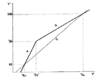
そして、点T’の色かぶり補正後の輝度成分YT'が点Tの輝度成分YTとなるようにコントラストを調整する。つまり図6に示すように(YT,YT')を屈折点とし、色かぶり補正後の輝度Y’がYT'より小さい場合は、輝度を直線aとして与えられる関数によりY”に補正し、YT'より大きい場合は、直線bとして与えられる関数によってY”に補正する。 Then, the contrast is adjusted so that the luminance component YT ′ after the color cast correction at the point T ′ becomes the luminance component YT at the point T. That is, as shown in FIG. 6, when (YT, YT ′) is a refraction point and the luminance Y ′ after color cast correction is smaller than YT ′, the luminance is corrected to Y ″ by a function given as a straight line a. If it is greater than ', it is corrected to Y "by a function given as a straight line b.
もちろん、このT,T’を使わずに、図6の直線l2で与えられるような補正をおこなってもよい。色立体軸が輝度軸と並行になる場合は、点T,T’は1対ではないし、また、T,T’が輝度の範囲[0,255]の外にある場合には、点(YT,YT')を屈折点とすることはできない。このような特殊なケースでは直線l2に従って補正すればよい。 Of course, the correction as given by the straight line l2 in FIG. 6 may be performed without using T and T '. When the color solid axis is parallel to the luminance axis, the points T and T ′ are not a pair, and when T and T ′ are outside the luminance range [0, 255], the point (YT , YT ′) cannot be the refraction point. In such a special case, correction may be made according to the straight line l2.
この2直線の最近接点T,T’を用いた補正の効果は、とくに露出のオーバーあるいはアンダーの画像に作用する。露出がオーバーになるのは空などの明るいところに画像全体が引っ張られるためである。この際デジタルカメラを代表する入力機器では、高輝度色抑圧が行われ、高輝度部の彩度がおとされる。すなわち、高輝度色抑圧の行われた画像の色立体軸を、図7(a)に示すように彩度と輝度とを軸とする2次元平面で考えると、高輝度の部分でもっとも無彩色に近い画素があらわれる。逆に、露出アンダーの画像に対しては低輝度色抑圧がかかるため、図7(b)のように、低輝度の部分で彩度が低くなる。 The effect of correction using the two straight line closest points T and T 'particularly affects an overexposed or underexposed image. The overexposure is because the entire image is pulled to a bright place such as the sky. At this time, in an input device typified by a digital camera, high luminance color suppression is performed, and saturation of the high luminance portion is reduced. That is, when the color solid axis of an image subjected to high luminance color suppression is considered as a two-dimensional plane having saturation and luminance as axes as shown in FIG. Pixels close to. On the contrary, since the low luminance color suppression is applied to the underexposed image, the saturation is lowered in the low luminance portion as shown in FIG. 7B.
実際の画像で色立体の輝度軸を輝度−彩度平面で考えると露出オーバーの画像に関しては例えば、図7(c)のようになる。逆にアンダーの画像に関しては例えば、図7(d)のようになる。そもそも本来あるべき(理想的な状態の)色立体から、なんらかの撮影状況や入力時(A/D変換時)の影響で実際の色立体がずれるのだと考えれば、T,T’の位置がもっともズレの小さい場所と考えられる。従って、本発明はこれを戻してやることで簡易的に適切なグレー、つまり全体の明るさ補正を行うものである。 Considering the luminance axis of the color solid in the luminance-saturation plane in an actual image, for example, an overexposed image is as shown in FIG. On the contrary, the under image is, for example, as shown in FIG. If the actual color solid is shifted from the original (ideal state) color solid by the influence of some shooting situation or input (A / D conversion), the positions of T and T ′ are It is considered to be the place with the smallest gap. Therefore, the present invention simply corrects the gray, that is, the overall brightness correction by returning this.
もちろんこのTを単に画像の露出オーバー・アンダーを簡易的に判定する手段として用い、あらかじめアンダー用のLUT(ルックアップテーブル)、オーバー用のLUTを用意し、点TあるいはT’の輝度成分に応じて輝度信号のガンマ調整を行ってもよい。例えば、図6の点(YT,YT’)を変曲点とするような曲線によってコントラストの調整を行ってもよい。従って、このT,T’の値によって簡易的に画像が露出オーバーなのか、アンダーなのか判定できる。すなわち、色立体軸においてもっとも彩度の低い点である点T’の輝度成分が高輝度よりにあれば、その画像の輝度−彩度の関係は図7(a)のような傾向を示すし、逆に点T’の輝度成分が低輝度よりにあれば、その画像の輝度−彩度の関係は図7(b)のような傾向を示す。したがって、高輝度色抑制及び低輝度色抑制された画像において、点T’の輝度成分が高輝度よりにあれば、その画像は露出オーバー傾向にあり、点T’の輝度成分が低輝度よりにあれば、その画像は露出アンダー傾向にあると考えられる。 Of course, this T is simply used as a means for simply determining whether the image is overexposed or underexposed, and an LUT (look-up table) for over and a LUT for over are prepared in advance, depending on the luminance component of the point T or T ′. Then, gamma adjustment of the luminance signal may be performed. For example, the contrast may be adjusted by a curve having the point (YT, YT ′) in FIG. 6 as an inflection point. Therefore, it is possible to easily determine whether the image is overexposed or underexposed based on the values of T and T ′. That is, if the luminance component of the point T ′, which is the point with the lowest saturation on the color solid axis, is higher than the luminance, the relationship between the luminance and saturation of the image shows a tendency as shown in FIG. On the contrary, if the luminance component at the point T ′ is lower than the low luminance, the luminance-saturation relationship of the image shows a tendency as shown in FIG. Therefore, in a high-luminance color-suppressed and low-luminance color-suppressed image, if the luminance component at the point T ′ is higher than the high luminance, the image tends to be overexposed, and the luminance component at the point T ′ is lower than the low luminance. If so, the image is considered underexposed.
一方、彩度調整は、色差C1,C2に彩度補正係数を乗ずることで簡単に行うことができる。例えば、彩度を20%あげる場合は、補正後の彩度は補正前の120%となることから、彩度補正係数を1.2として計算する。すなわち、
C1”=1.2×C1’、
C2”=1.2×C2’
として彩度補正を行うことができる。これは、(彩度)=sqrt(C1^2+C2^2)
で定義されることによる。
On the other hand, the saturation adjustment can be easily performed by multiplying the color differences C1 and C2 by a saturation correction coefficient. For example, when the saturation is increased by 20%, the saturation after the correction is 120% before the correction, and therefore the saturation correction coefficient is calculated as 1.2. That is,
C1 ″ = 1.2 × C1 ′,
C2 ″ = 1.2 × C2 ′
Saturation correction can be performed as follows. This is (saturation) = sqrt (C1 ^ 2 + C2 ^ 2)
By being defined in
(RGB空間への逆変換)
以上で本実施形態における各種補正が終了する。この時点で原画像の各画素は(R,G,B)の色信号データから(C1”,C2”,Y”)の色空間データに変換された状態にあるので、再度(R’,G’,B’)の色信号データに逆変換する。逆変換は以下の式により行う。
R’=Y”+C1”、
G’=Y”−(0.3/0.59)*C1”−(0.11/0.59)*C2”、
B’=Y”+C2”。
(Inverse conversion to RGB space)
The various corrections in this embodiment are thus completed. At this time, each pixel of the original image is in a state converted from the color signal data of (R, G, B) to the color space data of (C1 ″, C2 ″, Y ″), so again (R ′, G ', B') is converted back into color signal data, which is performed by the following equation.
R ′ = Y ″ + C1 ″,
G ′ = Y ″ − (0.3 / 0.59) * C1 ″ − (0.11 / 0.59) * C2 ″,
B ′ = Y ″ + C2 ″.
このようにして、原画像に対して、色かぶり,コントラスト、彩度が補正されたRGBデータを得ることができる。 In this way, RGB data in which the color cast, contrast, and saturation are corrected for the original image can be obtained.
以上のように、本実施形態によれば、少ない処理負荷で確実に色かぶり補正が可能となる。 As described above, according to the present embodiment, color cast correction can be reliably performed with a small processing load.
また、本実施形態によれば、サンプリング条件を原画像の画像データサイズに応じて設定しているので、入力画像にかかわらずヒストグラム総度数と、白位置及び黒位置を決定するための累積度数との関係をほぼ一定にすることができる。したがって、良好な色かぶり補正を実現することができる。 Further, according to the present embodiment, since the sampling condition is set according to the image data size of the original image, the histogram total frequency, the cumulative frequency for determining the white position and the black position, regardless of the input image, The relationship can be made almost constant. Therefore, it is possible to realize a good color cast correction.
さらに、補正対象画像の色立体軸と輝度軸との距離が最短となる点における輝度を維持するように画像全体を非線形にガンマ補正することで、もっとも原画像の値に近いと考えられる輝度を維持しつつ、コントラストを補正することができる。 Furthermore, the luminance that is considered to be closest to the value of the original image is obtained by nonlinearly gamma-correcting the entire image so as to maintain the luminance at the point where the distance between the color solid axis and the luminance axis of the correction target image is the shortest. The contrast can be corrected while maintaining.
さらに、画像が露出オーバーであるか露出アンダーであるかという露出状態を簡単に得ることができる。さらに、その露出状態に応じて異なるテーブルを選択し、ガンマ補正を施すこともできる。 Furthermore, it is possible to easily obtain an exposure state in which the image is overexposed or underexposed. Furthermore, a different table can be selected according to the exposure state and gamma correction can be performed.
なお、サンプリングをライン単位でなくカラム単位で行っても構わない。 Note that sampling may be performed not on a line basis but on a column basis.
[第2の実施の形態]
次に、上述した第1実施形態に対して、補正度合いを考慮した第2の実施形態について説明する。
[Second Embodiment]
Next, a second embodiment in consideration of the degree of correction will be described with respect to the first embodiment described above.
第1実施形態で説明したように、画像の色立体軸を求める際に、この軸の傾きがあまりにも大きい場合、これを無理に補正すると画像に不具合が生じる場合がある。これには例えば色フィルタなどをもちいて故意に色かぶりを起こしているような場合や、夕焼けのシーンを撮影した場合などが考えられる。 As described in the first embodiment, when the color solid axis of an image is obtained, if the inclination of the axis is too large, a problem may occur in the image if this is corrected forcibly. For example, a case where a color cast is intentionally caused using a color filter or a case where a sunset scene is photographed can be considered.
このような場合、求めたハイライトポイントとシャドーポイントが間違っていたと判断して補正を行わないか、または、回転角を適当に調整して補正度合いを弱めることで不具合をなくすことができる。このようなハイライトポイントとシャドーポイントが間違っていたという判定は、色立体軸の方向によって可能である。色立体軸の傾きから、どの色がかぶっているのか容易に判定できるので、特殊効果を得るために例えば色フィルタを用いて撮影された画像については色かぶりを補正しないというような判定もできる。 In such a case, it is possible to eliminate the problem by judging that the obtained highlight point and shadow point are wrong and not performing correction, or by appropriately adjusting the rotation angle to weaken the correction degree. Such a determination that the highlight point and the shadow point are wrong can be made according to the direction of the color solid axis. Since it is possible to easily determine which color is covered from the inclination of the color solid axis, it is possible to determine that the color cast is not corrected for an image photographed using, for example, a color filter in order to obtain a special effect.
このような場合、色立体軸の方向ベクトルと、輝度軸とのなす角度に着目し、色かぶり補正を行うことで逆に不都合が生じると判定して処理を行わないか、または、処理の度合をゆるめる。例えば、色立体軸が赤の色相方向に向いており、その角度が所定の角度、例えば40度以上の場合には、その画像は本来色かぶりした画像であると判断する。処理の度合をゆるめる場合には、色立体軸を所定角度、例えば20度だけ起こしたり、あるいは所定角度まで、例えばY軸に対する傾きが20度になるまで起こすことで色かぶりを補正する。この変換のための回転行列は、回転軸と回転角度とから容易に求めることができる。 In such a case, pay attention to the angle formed between the direction vector of the color solid axis and the luminance axis, and it is determined that inconvenience will occur if color fog correction is performed, or processing is not performed, or the degree of processing Loosen For example, when the color solid axis is oriented in the hue direction of red and the angle is a predetermined angle, for example, 40 degrees or more, it is determined that the image is originally a color cast image. When the degree of processing is loosened, the color cast is corrected by raising the color solid axis by a predetermined angle, for example, 20 degrees, or up to a predetermined angle, for example, until the inclination with respect to the Y axis becomes 20 degrees. The rotation matrix for this conversion can be easily obtained from the rotation axis and the rotation angle.
なお上記補正の度合いはユーザーがマニュアルで指定してもいいし、あらかじめ角度の大きさ、該色立体軸の方向に応じて設定しておいてもよい。例えば40度の場合、該画像の色立体を20度だけ回転して起こすとしたが、その補正の度合いをユーザに指定させてもよい。以後の処理は第1実施形態と同様である。 The degree of correction may be manually specified by the user, or may be set in advance according to the size of the angle and the direction of the color solid axis. For example, in the case of 40 degrees, the color solid of the image is rotated by 20 degrees, but the degree of correction may be specified by the user. The subsequent processing is the same as in the first embodiment.
また、色立体軸の方向によって、どの色がかぶっているのか容易に判定できるので、特殊効果を得るために例えば色フィルタを用いて撮影された画像については、フィルタの色方向に関しては補正しないというような判定もできる。すなわちこのような場合には、色かぶりを補正しない色を指定させ、C1−C2平面上において、補正を行わない色の方向に沿って回転変換の回転軸を設定し、その回転軸と色立体軸lとを含む平面が、Y軸と平行になるまで色立体を回転変換する。こうすることで、特定の色成分についてだけ色かぶりを補正できる。 In addition, since it can be easily determined which color is covered by the direction of the color solid axis, for example, for an image photographed using a color filter in order to obtain a special effect, the color direction of the filter is not corrected. Such a determination can also be made. That is, in such a case, a color that does not correct the color cast is designated, a rotation axis of rotation conversion is set along the direction of the color that is not corrected on the C1-C2 plane, and the rotation axis and the color solid are set. The color solid is rotated and converted until the plane including the axis l is parallel to the Y axis. In this way, the color cast can be corrected only for a specific color component.
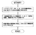
図10は、色立体軸が所定角度以上傾いている場合には、別途指定された角度まで色立体を回転させるように、画像を補正するための処理手順である。まず、ステップS101でハイライト/シャドーポイントを決定し、ステップS102で色立体軸の傾きが所定角度以上であるか判定する。もし所定角度に達していなければ、ステップS104,S105で、第1の実施の形態と同様に、色立体軸が輝度軸と一致するように変換して色かぶりを補正する。 FIG. 10 shows a processing procedure for correcting an image so that the color solid is rotated to a separately designated angle when the color solid axis is inclined by a predetermined angle or more. First, a highlight / shadow point is determined in step S101, and it is determined in step S102 whether the inclination of the color solid axis is equal to or greater than a predetermined angle. If the predetermined angle has not been reached, the color cast is corrected in steps S104 and S105 by converting the color solid axis so as to coincide with the luminance axis in the same manner as in the first embodiment.
一方、色立体軸が所定角度以上傾いていれば、色立体軸を、輝度軸に向かって20度だけ回転させるような回転行列をステップS103で求め、ステップS105で、その回転行列を用いて色立体を回転させて色かぶりを補正する。この場合、ステップS103で用いた20度という角度は、いかように指定しても構わない。 On the other hand, if the color solid axis is inclined by a predetermined angle or more, a rotation matrix that rotates the color solid axis by 20 degrees toward the luminance axis is obtained in step S103, and in step S105, the color matrix is used by using the rotation matrix. Rotate the solid to correct the color cast. In this case, the angle of 20 degrees used in step S103 may be specified in any way.
なお、しきい値を2段階設け、第1のしきい値(例えば40度)より色立体軸の傾きが大きい場合には、色立体軸を完全なグレーラインにしない程度に色立体軸を起こす(例えば20度)ように回転変換し、第1のしきい値と第2のしきい値(例えば20度)との間の場合には、回転変換を行わず、第2のしきい値よりも傾きが小さい場合には、色立体軸を輝度軸と一致させるように回転変換を行うこともできる。このようにすることで、意図的に色かぶりが生じさせられた画像については、不都合な補正を行うことがない。 If the threshold of the color solid axis is larger than the first threshold (for example, 40 degrees), the color solid axis is raised to the extent that the color solid axis is not a complete gray line. (For example, 20 degrees), the rotation conversion is performed, and if it is between the first threshold value and the second threshold value (for example, 20 degrees), the rotation conversion is not performed and the second threshold value is used. If the inclination is small, rotation conversion can be performed so that the color solid axis coincides with the luminance axis. By doing so, an inconvenient correction is not performed on an image in which a color cast is intentionally generated.
このように、画像データの画素により構成される色立体の軸の傾き、すなわち軸の方向と傾きの角度という2つの量から、補正するか否かのしきい値をすくなくとも2つ以上設定し画像を補正すべきか、すべきでない、補正度合いを調節すべきかの判定を行うことができ、非常に簡潔に特殊なケースの弊害だけをはじくことができる。 In this way, at least two threshold values for whether or not to correct are set from two amounts of the inclination of the axis of the color solid composed of pixels of the image data, that is, the direction of the axis and the angle of inclination. It is possible to determine whether the correction should be corrected or not, and the correction degree should be adjusted, so that only the harmful effects of a special case can be rejected very simply.
また、色立体軸の方向によって、どの色がかぶっているのか容易に判定できるので、かぶっている色方向に応じて色かぶりを補正しないようにすることもできる。 Further, since it is possible to easily determine which color is covered according to the direction of the color solid axis, it is possible not to correct the color cast according to the color direction.
[第3の実施の形態]
前記第1〜第2実施形態では、画像のハイライトポイント・シャドーポイントに基づいた色バランス補正について説明したが、この他の基準点に基づく補正の実施例について以下説明する。
[Third Embodiment]
In the first and second embodiments, the color balance correction based on the highlight point and the shadow point of the image has been described. Examples of correction based on other reference points will be described below.
まず、ハイライトポイントおよびシャドーポイントにおける平均色差量△Eを求める。
△E=sqrt((C1HL−C1SD)^2+(C2HL−C2SD)^2)。
色立体軸が輝度軸と平行であればΔE=0となるはずであるが、傾いていれば、0より大きな値となる。つまり、E(彩度)−Y(輝度)平面で考えると図8のようになる。
First, an average color difference amount ΔE at a highlight point and a shadow point is obtained.
ΔE = sqrt ((C1HL−C1SD) ^ 2 + (C2HL−C2SD) ^ 2).
If the color solid axis is parallel to the luminance axis, ΔE = 0 should be obtained, but if the color solid axis is inclined, the value is larger than 0. That is, FIG. 8 shows the E (saturation) -Y (luminance) plane.
次にハイライトとシャドーの間のサンプル輝度を数点用意する。そして、画像中で例えば輝度Ynの画素から、△Enより小さい彩度の画素を用いて、図8のように平均色差量を求める。ΔEnとしては、予め設定した一定彩度を用いてもよいし、また、色立体軸の傾き方向に限定した平均色差量を求めてもよい。 Next, prepare several sample luminances between highlight and shadow. Then, an average color difference amount is obtained as shown in FIG. 8 using pixels having a saturation smaller than ΔEn from pixels having luminance Yn in the image, for example. As ΔEn, a preset constant saturation may be used, or an average color difference amount limited to the inclination direction of the color solid axis may be obtained.
これらの数点の輝度について平均色差で最小二乗法的に直線を求め、これを色立体軸として第1実施形態に基づく処理を行う。 For these several luminance points, a straight line is obtained in the least-squares manner with an average color difference, and processing based on the first embodiment is performed using this as a color solid axis.
あるいは、求められた色差及び輝度を要素とする点をBシュプラインなどで近似曲線を求め、この曲線を輝度軸にする、すなわち色差を“0”とするように非線形の色バランス補正を行ってもよい。 Alternatively, an approximate curve is obtained by using a B-Spline or the like with the obtained color difference and luminance as elements, and this curve is used as a luminance axis, that is, nonlinear color balance correction is performed so that the color difference is “0”. Also good.
以上本発明を好ましい実施例により説明したが、本発明は上述した実施例に限ることなく、クレームに示した範囲で種々の変形が可能である。 Although the present invention has been described with reference to the preferred embodiments, the present invention is not limited to the above-described embodiments, and various modifications can be made within the scope shown in the claims.
このようにすることで、輝度軸となるべき線を、ハイライト及びシャドーだけではなく、画像全体から一様にサンプリングした画素から得ることができる。得られた線を輝度軸に一致するように画像データを変換することで、画像全体の特性を反映した色かぶり補正を行うことができる。 By doing in this way, the line which should become a brightness | luminance axis | shaft can be obtained from the pixel sampled uniformly from not only the highlight and the shadow but the whole image. By converting the image data so that the obtained line coincides with the luminance axis, color cast correction reflecting the characteristics of the entire image can be performed.
[他の実施形態]
なお、本発明は、複数の機器(例えばホストコンピュータ,インタフェイス機器,リーダ,プリンタなど)から構成されるシステムに適用しても、一つの機器からなる装置(例えば、複写機,ファクシミリ装置など)に適用してもよい。
[Other Embodiments]
Note that the present invention can be applied to a system including a plurality of devices (for example, a host computer, an interface device, a reader, a printer, etc.), or a device (for example, a copier, a facsimile device, etc.) including a single device You may apply to.
また、本発明の目的は、前述した実施形態の機能を実現するための、図3,4,9,10に示した手順のプログラムコードを記録した記憶媒体を、システムあるいは装置に供給し、そのシステムあるいは装置のコンピュータ(またはCPUやMPU)が記憶媒体に格納されたプログラムコードを読出し実行することによっても達成される。 In addition, an object of the present invention is to supply a storage medium in which a program code of the procedure shown in FIGS. 3, 4, 9, and 10 for realizing the functions of the above-described embodiments is supplied to a system or apparatus. This can also be achieved by a computer (or CPU or MPU) of the system or apparatus reading and executing the program code stored in the storage medium.
この場合、記憶媒体から読出されたプログラムコード自体が前述した実施形態の機能を実現することになり、そのプログラムコードを記憶した記憶媒体は本発明を構成することになる。 In this case, the program code itself read from the storage medium realizes the functions of the above-described embodiments, and the storage medium storing the program code constitutes the present invention.
プログラムコードを供給するための記憶媒体としては、例えば、フレキシブルディスク,ハードディスク,光ディスク,光磁気ディスク,CD−ROM,CD−R,磁気テープ,不揮発性のメモリカード,ROMなどを用いることができる。 As a storage medium for supplying the program code, for example, a flexible disk, a hard disk, an optical disk, a magneto-optical disk, a CD-ROM, a CD-R, a magnetic tape, a nonvolatile memory card, a ROM, or the like can be used.
また、コンピュータが読出したプログラムコードを実行することにより、前述した実施形態の機能が実現されるだけでなく、そのプログラムコードの指示に基づき、コンピュータ上で稼働しているOS(オペレーティングシステム)などが実際の処理の一部または全部を行い、その処理によって前述した実施形態の機能が実現される場合も含まれる。 Further, by executing the program code read by the computer, not only the functions of the above-described embodiments are realized, but also an OS (operating system) operating on the computer based on the instruction of the program code. A case where part or all of the actual processing is performed and the functions of the above-described embodiments are realized by the processing is also included.
さらに、記憶媒体から読出されたプログラムコードが、コンピュータに挿入された機能拡張ボードやコンピュータに接続された機能拡張ユニットに備わるメモリに書込まれた後、そのプログラムコードの指示に基づき、その機能拡張ボードや機能拡張ユニットに備わるCPUなどが実際の処理の一部または全部を行い、その処理によって前述した実施形態の機能が実現される場合も含まれる。 Further, after the program code read from the storage medium is written into a memory provided in a function expansion board inserted into the computer or a function expansion unit connected to the computer, the function expansion is performed based on the instruction of the program code. This includes a case where the CPU or the like provided in the board or the function expansion unit performs part or all of the actual processing, and the functions of the above-described embodiments are realized by the processing.
Claims (27)
前記ハイライトポイントおよびシャドーポイントの色みを求め、
前記ハイライトポイント、前記シャドーポイントおよび前記色みに基づき、前記ハイライトポイント、前記シャドーポイントを明るさと色みの空間における明るさを示す軸に向かい少なくとも回転させる行列を算出し、
前記原画像の各画素に、前記行列に従い色かぶり補正をすることを特徴とする画像処理方法。 Using an image obtained by reducing the number of pixels from an original image taken by a digital camera, a highlight point and a shadow point of the original image are detected,
Find the highlight point and shadow point color,
Based on the highlight point, the shadow point, and the color , calculate a matrix that at least rotates the highlight point, the shadow point toward an axis indicating brightness in brightness and color space ,
An image processing method , wherein color fog correction is performed on each pixel of the original image according to the matrix .
前記ハイライトポイントおよびシャドーポイントの色みを求める手段と、
前記ハイライトポイント、前記シャドーポイントおよび前記色みに基づき、前記ハイライトポイント、前記シャドーポイントを明るさと色みの空間における明るさを示す軸に向かい少なくとも回転させる行列を算出する手段と、
前記原画像の各画素に、前記行列に従い色かぶり補正をする手段と
を有することを特徴とする画像処理装置。 Means for detecting highlight points and shadow points of the original image using an image obtained by reducing the number of pixels from the original image taken by the digital camera ;
Means for determining the color of the highlight point and shadow point;
Means for calculating a matrix that at least rotates the highlight point, the shadow point toward an axis indicating brightness in brightness and tint space based on the highlight point, the shadow point, and the tint ;
Means for correcting color fog according to the matrix on each pixel of the original image;
An image processing apparatus comprising:
前記ハイライトポイントおよびシャドーポイントの色みを求め、
前記ハイライトポイント、前記シャドーポイントおよび前記色みに基づき、前記ハイライトポイント、前記シャドーポイントを明るさと色みの空間における明るさを示す軸に向かい少なくとも回転させる行列を算出し、
前記原画像の各画素を、前記行列に従い色かぶり補正し、
前記補正後の画像データにプリンタ用の画像信号変換をおこなうことを特徴とする画像処理方法。 Using an image obtained by reducing the number of pixels from an original image taken by a digital camera, a highlight point and a shadow point of the original image are detected,
Find the highlight point and shadow point color,
Based on the highlight point, the shadow point, and the color, calculate a matrix that at least rotates the highlight point, the shadow point toward an axis indicating brightness in brightness and color space,
Each pixel of the original image is color cast corrected according to the matrix,
An image processing method, wherein image signal conversion for a printer is performed on the corrected image data .
前記ハイライトポイントおよびシャドーポイントの色みを求める手段と、
前記ハイライトポイント、前記シャドーポイントおよび前記色みに基づき、前記ハイライトポイント、前記シャドーポイントを明るさと色みの空間における明るさを示す軸に向かい少なくとも回転させる行列を算出する手段と、
前記原画像の各画素を、前記行列に従い色かぶり補正する手段と、
前記補正後の画像データにプリンタ用の画像信号変換をおこなう手段と
を有することを特徴とする画像処理装置。 Means for detecting highlight points and shadow points of the original image using an image obtained by reducing the number of pixels from the original image taken by the digital camera ;
Means for determining the color of the highlight point and shadow point;
Means for calculating a matrix that at least rotates the highlight point, the shadow point toward an axis indicating brightness in brightness and tint space based on the highlight point, the shadow point, and the tint;
Means for correcting color cast according to the matrix for each pixel of the original image;
Means for performing image signal conversion for a printer on the corrected image data;
An image processing apparatus comprising:
Priority Applications (1)
| Application Number | Priority Date | Filing Date | Title |
|---|---|---|---|
| JP2008079195A JP4909308B2 (en) | 2008-03-25 | 2008-03-25 | Image processing method and apparatus |
Applications Claiming Priority (1)
| Application Number | Priority Date | Filing Date | Title |
|---|---|---|---|
| JP2008079195A JP4909308B2 (en) | 2008-03-25 | 2008-03-25 | Image processing method and apparatus |
Related Parent Applications (1)
| Application Number | Title | Priority Date | Filing Date |
|---|---|---|---|
| JP2005373522A Division JP4402041B2 (en) | 2005-12-26 | 2005-12-26 | Image processing method and apparatus, and storage medium |
Related Child Applications (1)
| Application Number | Title | Priority Date | Filing Date |
|---|---|---|---|
| JP2010088188A Division JP4909428B2 (en) | 2010-04-06 | 2010-04-06 | Image processing method and apparatus |
Publications (2)
| Publication Number | Publication Date |
|---|---|
| JP2008167504A JP2008167504A (en) | 2008-07-17 |
| JP4909308B2 true JP4909308B2 (en) | 2012-04-04 |
Family
ID=39696224
Family Applications (1)
| Application Number | Title | Priority Date | Filing Date |
|---|---|---|---|
| JP2008079195A Expired - Fee Related JP4909308B2 (en) | 2008-03-25 | 2008-03-25 | Image processing method and apparatus |
Country Status (1)
| Country | Link |
|---|---|
| JP (1) | JP4909308B2 (en) |
Family Cites Families (5)
| Publication number | Priority date | Publication date | Assignee | Title |
|---|---|---|---|---|
| JP2893682B2 (en) * | 1987-12-23 | 1999-05-24 | ミノルタ株式会社 | Color image processing method |
| JPH07222011A (en) * | 1994-01-31 | 1995-08-18 | Canon Inc | Method for color reproduction range expression method, and method and device for processing image |
| JPH08223433A (en) * | 1995-02-15 | 1996-08-30 | Fuji Xerox Co Ltd | Color image processing method |
| JP2914228B2 (en) * | 1995-06-22 | 1999-06-28 | 日本ビクター株式会社 | Color reproduction processing method |
| JPH10178557A (en) * | 1996-10-14 | 1998-06-30 | Oki Data:Kk | Color image processing method |
-
2008
- 2008-03-25 JP JP2008079195A patent/JP4909308B2/en not_active Expired - Fee Related
Also Published As
| Publication number | Publication date |
|---|---|
| JP2008167504A (en) | 2008-07-17 |
Similar Documents
| Publication | Publication Date | Title |
|---|---|---|
| JP4194133B2 (en) | Image processing method and apparatus, and storage medium | |
| US7929761B2 (en) | Image processing method and apparatus and storage medium | |
| JP4006347B2 (en) | Image processing apparatus, image processing system, image processing method, storage medium, and program | |
| US6608926B1 (en) | Image processing method, image processing apparatus and recording medium | |
| US7242800B2 (en) | Image processing apparatus, image processing system, image processing method, storage medium, and program | |
| JP2005210370A (en) | Image processor, photographic device, image processing method, image processing program | |
| JP2005210495A (en) | Image processing apparatus, method, and program | |
| JP3950551B2 (en) | Image processing method, apparatus, and recording medium | |
| JP4402041B2 (en) | Image processing method and apparatus, and storage medium | |
| JP2000013625A (en) | Image processing method, device and recording medium | |
| JP4909308B2 (en) | Image processing method and apparatus | |
| JP4818459B2 (en) | Image processing method and apparatus | |
| JP4909428B2 (en) | Image processing method and apparatus | |
| JP3817371B2 (en) | Image processing method, apparatus, and recording medium | |
| JP2002094810A (en) | Picture processor, picture processing method and memory medium having stored programs for the method | |
| JP4208889B2 (en) | Image processing method, apparatus, and recording medium | |
| JP4411357B2 (en) | Image processing method, apparatus, and recording medium | |
| JP2000013595A (en) | Image processing method, device and recording medium |
Legal Events
| Date | Code | Title | Description |
|---|---|---|---|
| A131 | Notification of reasons for refusal |
Free format text: JAPANESE INTERMEDIATE CODE: A131 Effective date: 20100205 |
|
| A521 | Written amendment |
Free format text: JAPANESE INTERMEDIATE CODE: A523 Effective date: 20100406 |
|
| A02 | Decision of refusal |
Free format text: JAPANESE INTERMEDIATE CODE: A02 Effective date: 20100712 |
|
| A01 | Written decision to grant a patent or to grant a registration (utility model) |
Free format text: JAPANESE INTERMEDIATE CODE: A01 |
|
| A61 | First payment of annual fees (during grant procedure) |
Free format text: JAPANESE INTERMEDIATE CODE: A61 Effective date: 20120113 |
|
| FPAY | Renewal fee payment (event date is renewal date of database) |
Free format text: PAYMENT UNTIL: 20150120 Year of fee payment: 3 |
|
| FPAY | Renewal fee payment (event date is renewal date of database) |
Free format text: PAYMENT UNTIL: 20150120 Year of fee payment: 3 |
|
| LAPS | Cancellation because of no payment of annual fees |