JP4900668B2 - Airtight container with lid - Google Patents
Airtight container with lid Download PDFInfo
- Publication number
- JP4900668B2 JP4900668B2 JP2006125339A JP2006125339A JP4900668B2 JP 4900668 B2 JP4900668 B2 JP 4900668B2 JP 2006125339 A JP2006125339 A JP 2006125339A JP 2006125339 A JP2006125339 A JP 2006125339A JP 4900668 B2 JP4900668 B2 JP 4900668B2
- Authority
- JP
- Japan
- Prior art keywords
- plate
- hook
- push button
- push
- front wall
- Prior art date
- Legal status (The legal status is an assumption and is not a legal conclusion. Google has not performed a legal analysis and makes no representation as to the accuracy of the status listed.)
- Expired - Fee Related
Links
- 230000037431 insertion Effects 0.000 claims description 3
- 238000003780 insertion Methods 0.000 claims description 3
- 210000000078 claw Anatomy 0.000 description 5
- 230000002093 peripheral effect Effects 0.000 description 3
- 238000000605 extraction Methods 0.000 description 2
- 230000000630 rising effect Effects 0.000 description 1
Images




Landscapes
- Closures For Containers (AREA)
Description
本発明はコンパクト等容器に関する。 The present invention relates to a compact container.
容器本体後部に、該容器本体上面を開閉する蓋体を枢着させ、容器本体周壁の前壁前面に、押板後面から屈曲部を介して押圧子を後方突出する押釦を前後方向への摺動が自在に装着させ、上記押圧子を、前壁前面から前方突出するガイド板上面が形成する斜下前方への傾斜面へ載置し、又該ガイド板上方の前壁前面へ付設した係合子へ、蓋体前部から垂設したフックを係合させ、上記押釦後方押込みで傾斜面に沿って押圧子が上昇して該押圧子の後端部上縁がフック下端面を押上げて上記係合からフックが外れるよう設けたコンパクト等容器が知られている。(特許資料1)。
上記従来例は、押釦後方押込みにより、押釦板の後面から屈曲部を介して後方突出する押圧子が上昇傾斜面に沿って移動することでの押圧子後端部の上昇でフック下端面を押上げ、該押上げにより係合子下面に係合するフックを強制的に押上げるから、フックと係合子との係合が多いとその離脱が困難となる欠点があった。本発明は押釦後方押込みによりフックを前方移動させて、上記係合子とフックとの係合面積を少くできる弾性板を押釦に付設させ、上記押圧子によるフックの押上げが容易としたものである。 In the above conventional example, when the push button is pushed backward, the pusher protruding rearward from the rear surface of the pushbutton plate through the bent portion moves along the rising slope surface, and the lower end surface of the pusher is pushed by the rise of the pusher rear end portion. The hook that is engaged with the lower surface of the engaging element is forcibly pushed up by the lifting operation, so that there is a drawback that it is difficult to disengage the hook when the engagement between the hook and the engaging element is large. According to the present invention, the hook is moved forward by pushing the push button backward, and an elastic plate capable of reducing the engagement area between the engagement element and the hook is attached to the push button, so that the hook can be easily pushed up by the push element. .
第1の手段として、
押板9後面から屈曲部を介して押圧子11を後方突出する押釦8を、前後方向への摺動自在に容器本体前壁前面へ装着させて、上記押圧子11を、前壁前面から前方突出するガイド板12上面が形成する斜下前方への傾斜面13上へ載置し、又該ガイド板12上方の前壁前面へ付設した係合突条6へ、蓋体前部から垂下させたフック4の爪5を係合させ、
上記押釦後方押込みで、傾斜面に沿って上昇した押圧子11の後端部がフック下端面を押上げて係合突条6から離脱可能に形成したコンパクト等容器において、
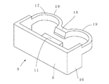
上記押板9の左右両端から左右両側板16を後方突出して、これら左右両側板16の各後端間に、上方からみてほぼ数字の3字形状の弾性板17を、該弾性板の両端を上記側板(16)の各後端に連結させて設け、又該弾性板17挿入用凹部20を上記係合突条6と傾斜面13上端との間の本体前壁部分へ穿設して、上記押釦装着状態からの後方押込みで、弾性板後面の左右両部に形成される後方突出部19、19が凹部20の後壁に圧接して弾性変形することで弾性板17の中間部18が前進して上記フック4の下部を前方押出し可能に形成した。
As a first means,
A
In a compact container such that the rear end of the
The left and
第2の手段として、上記第1の手段を有すると共に上記中間部18がフック4の前方押出しを開始した後に、傾斜面13を摺動して上昇する押圧子11後端部上面がフック下端面を押上げ可能に形成した。
As a second means, the upper surface of the rear end portion of the
第3の手段として、上記第1又は第2の手段を有すると共に、
上記ガイド板12下方の前壁部分に前面開口の台板挿入用の穴14を穿設し、又押釦の押板9下端部から後端部下面に係合突子21を付設した台板15を上記穴14内へ進退自在に挿入させ、押釦8と共に台板15が前進したとき上記係合突子21が上記穴14内下面に形成した後向き段部14aへ係合して押釦8の前方抜出しを不能に形成した。
As the third means, the first or second means is provided,
A
請求項1記載のようにすることで、押釦8後方押込みによる該押釦から後方突出させた弾性板17の中間部18がフック下部を前方へ押出すこととなり、よってフック下端の爪と容器本体前壁前面に設けた係合子との係合面積を少くでき、よって押釦押圧子11によるフック4の押上げが容易となる。
According to the first aspect, the
請求項2のようにすることで、上記中間部18によるフック前方押出しが容易となって押圧子11によるフック押上げが更に容易となる。
According to the second aspect, the hook forward pushing by the
請求項3のようにすることで、容器本体前壁からの押釦抜け出しを確実に防止できる。 According to the third aspect, it is possible to reliably prevent the push button from coming out from the front wall of the container body.
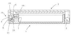
以下図面について説明する。まず従来公知の部分について簡単に説明すると1はコンパクト等容器の容器本体で、該容器本体周壁の後部には、該容器本体上面を開閉する蓋体2がピン3で枢着させてあり、該蓋体前部からはフック4を垂下させ、該フックの下部下面に付設した爪5を容器本体周壁前壁7の上部前面へ付設した係合突条6下面へ係合させて蓋体閉塞状態を保持可能といている。
The drawings will be described below. First, a conventionally known part will be briefly described.
又容器本体前壁7の前面へは、上記フック押上げ用の押釦8が装着させてある。該押釦は、押板9の後面から屈曲部10を介して押圧子11を後方へ突出し、該押圧子を容器本体前壁から前方突出したガイド板12の前部上面へ載置させ、押板9を後方へ押込みすると、上記押圧子がガイド板12上面へ形成した、斜下前方への傾斜面13に沿って押上げられることで、その押圧子の後端部上縁がフック4下端面を押上げして、既述係合突条6へ係合する爪5を外し蓋体前部が上昇可能としている。
The
上記ガイド板12下方の前壁部分には、前面開口の台板挿入用の穴14が穿設してあり、該穴内へ押釦の押板9下端から後方突出させた台板15が挿入させてある。
The front wall portion below the
上記構成において本願発明にあっては、既述押釦8を、図4から図6が示すように押釦の左右両側板16の各後端間に、上方からみてほぼ数字の3字形状の弾性板17を、その左右方向中間部18を前方突出させ、かつその中間部左右の両後方突出部19を後方突出させて設け、その弾性板17を、図2が示すように、既述係合突条6と傾斜面13上端との開口の前壁部分に穿設した、前面開口の凹部20内へ嵌合させた。該嵌合状態で既述後方突出部19の各後面は図2が示すように凹部20の後壁面に近接ないしほぼ接し、又このとき上記中間部18は図2が示すようにフック4の爪5下方部分後面へほぼ接するよう設け、該状態から押板9を後方へ押込みすると、図3が示すように、既述両後方突出部19、19が凹部20の後壁面へ押付けられることで中間部18が前方へ押出され、よってその中間部18の前面がフック4の爪下方部分を図3のように前方へ押出し、該押出しでフックの爪5が既述係合突条6下面から前方へ押出しされるよう設ける。尚このとき押釦の押圧子11は押釦後方押込みにより傾斜面13に沿い上昇することで、その押圧子の後面上端はフック下端面を押し上げ、よってそれ等中間部前面の前進と、押圧子後面上端の上昇とによりフック4の爪5は係合突条6から外されてフック4は押上げられる。
該状態から押釦の後方押込みを解放すると、弾性板17は弾性復帰し、よって押圧子11および弾性板の中間部17は元の位置へ復帰し、又押圧子11は傾斜面13を下降してガイド板12の前端部上面へ復帰する。
In the present invention having the above-described configuration, the
When the rear push of the push button is released from this state, the
尚既述台板15の後端部下面へは係合突子21が付設してあって、押釦復帰時に既述穴14内下面に設けた後向き段部14aへ係合して該押釦8の前方抜出しを防止する。
An
1 容器本体 4 フック
6 係合突条 8 押釦
10 屈曲部 11 押圧子
12 ガイド板 13 傾斜面
15 台板 17 弾性板
18 中間部 19 後方突出部
1
10
12
15
18
Claims (3)
上記押釦後方押込みで、傾斜面に沿って上昇した押圧子(11)の後端部がフック下端面を押上げて係合突条(6)から離脱可能に形成したコンパクト等容器において、
上記押板(9)の左右両端から左右両側板(16)を後方突出して、これら左右両側板(16)の各後端間に、上方からみてほぼ数字の3字形状の弾性板(17)を、該弾性板の両端を上記側板(16)の各後端に連結させて設け、又該弾性板(17)挿入用凹部(20)を上記係合突条(6)と傾斜面(13)上端との間の本体前壁部分へ穿設して、上記押釦装着状態からの後方押込みで、弾性板後面の左右両部に形成される後方突出部(19,19)が凹部(20)の後壁に圧接して弾性変形することで弾性板(17)の中間部(18)が前進して上記フック(4)の下部を前方押出し可能に形成した
ことを特徴とするコンパクト等の容器。 Push plate to push button (8) to rearward projection (9) pressing elements from the rear via a bend (11), by attaching to slidably container body front wall front surface of the front-rear direction, the pushing element (11 ) Is placed on the slanted front surface ( 13 ) formed by the upper surface of the guide plate ( 12 ) protruding forward from the front surface of the front wall, and attached to the front surface of the front wall above the guide plate ( 12 ) . to engage ridges (6), engaging the pawl (5) of the hook is suspended from the lid front (4),
In a compact container such that the rear end of the presser ( 11 ) raised along the inclined surface by pushing the rear side of the push button pushes up the lower end surface of the hook and is detachable from the engaging protrusion ( 6 ) .
The left and right side plates (16) protrude rearward from the left and right ends of the push plate (9), and between the rear ends of the left and right side plates (16), a substantially 3-digit elastic plate (17) viewed from above The elastic plate is provided with both ends thereof connected to the respective rear ends of the side plate (16) , and the elastic plate ( 17 ) insertion recess ( 20 ) is provided with the engaging protrusion ( 6 ) and the inclined surface ( 13 ). ) Drilled in the front wall portion of the main body between the upper end and the rear protrusions ( 19, 19 ) formed on both the left and right portions of the rear surface of the elastic plate by the rear push-in from the push button mounted state are the recesses ( 20 ) A compact container or the like characterized in that the intermediate portion ( 18 ) of the elastic plate ( 17 ) moves forward by pressing against the rear wall and elastically deforms so that the lower portion of the hook ( 4 ) can be pushed forward. .
ことを特徴とする請求項1記載のコンパクト等容器。 After the intermediate part ( 18 ) starts to push the hook ( 4 ) forward, the upper surface of the rear end of the presser ( 11 ) that slides and rises by sliding on the inclined surface ( 13 ) is formed so that the lower end of the hook can be pushed up. The compact container according to claim 1, wherein the container is a compact container.
ことを特徴とする請求項1又は2記載のコンパクト等容器。 The guide plate (12) engages the rear end lower surface from the front wall section is drilled a hole (14) for the base plate insertion of the front opening, and a push button of the push plate (9) the lower end of the lower projections ( 21) a base plate that attached to the (15) is inserted retractably into the bore (14) within the engaging projections (21) of said hole when the base plate together with the push button (8) (15) has been advanced ( 14) The compact container according to claim 1 or 2, wherein the push button ( 8 ) is formed so as to be unable to be pulled out forward by engaging with a rearward stepped portion ( 14a ) formed on the inner and lower surfaces.
Priority Applications (1)
| Application Number | Priority Date | Filing Date | Title |
|---|---|---|---|
| JP2006125339A JP4900668B2 (en) | 2006-04-28 | 2006-04-28 | Airtight container with lid |
Applications Claiming Priority (1)
| Application Number | Priority Date | Filing Date | Title |
|---|---|---|---|
| JP2006125339A JP4900668B2 (en) | 2006-04-28 | 2006-04-28 | Airtight container with lid |
Publications (2)
| Publication Number | Publication Date |
|---|---|
| JP2007296046A JP2007296046A (en) | 2007-11-15 |
| JP4900668B2 true JP4900668B2 (en) | 2012-03-21 |
Family
ID=38766076
Family Applications (1)
| Application Number | Title | Priority Date | Filing Date |
|---|---|---|---|
| JP2006125339A Expired - Fee Related JP4900668B2 (en) | 2006-04-28 | 2006-04-28 | Airtight container with lid |
Country Status (1)
| Country | Link |
|---|---|
| JP (1) | JP4900668B2 (en) |
Families Citing this family (2)
| Publication number | Priority date | Publication date | Assignee | Title |
|---|---|---|---|---|
| KR101389317B1 (en) * | 2011-07-25 | 2014-04-28 | 주식회사 리홈쿠첸 | Opening assembly for the inner pot cover |
| JP7292809B2 (en) * | 2019-12-27 | 2023-06-19 | 株式会社吉野工業所 | compact container |
Family Cites Families (3)
| Publication number | Priority date | Publication date | Assignee | Title |
|---|---|---|---|---|
| JPS60173212A (en) * | 1984-02-15 | 1985-09-06 | Kaiyo Kogyo Kk | Compacting work of soft ground |
| JP4387080B2 (en) * | 2002-01-29 | 2009-12-16 | 株式会社吉野工業所 | Compact container for makeup |
| JP2005245949A (en) * | 2004-03-08 | 2005-09-15 | Yoshida Industry Co Ltd | Compact container |
-
2006
- 2006-04-28 JP JP2006125339A patent/JP4900668B2/en not_active Expired - Fee Related
Also Published As
| Publication number | Publication date |
|---|---|
| JP2007296046A (en) | 2007-11-15 |
Similar Documents
| Publication | Publication Date | Title |
|---|---|---|
| JPH0746167Y2 (en) | buckle | |
| JP4356567B2 (en) | connector | |
| KR20090092276A (en) | Connector position assurance device and a connector assembly incorporating the connector position assurance device | |
| JP2007044535A (en) | Slide fastener and slide fastener | |
| JP4432797B2 (en) | connector | |
| JP2005166604A (en) | Lock structure of connector | |
| CN114175416A (en) | Connector with a locking member | |
| JP2009231069A (en) | Locked connector for fpc | |
| JP2001085109A (en) | Connector | |
| JPH0667324B2 (en) | buckle | |
| CN100589731C (en) | Self-locking zipper pull | |
| JP6462510B2 (en) | buckle | |
| JP4175254B2 (en) | connector | |
| JP2007296046A (en) | Highly airtight container with lid | |
| JP3948525B2 (en) | Terminal disengagement jig | |
| JP4549653B2 (en) | Cosmetic container | |
| US6974354B2 (en) | Bulb assembly | |
| JP4457936B2 (en) | connector | |
| KR200466409Y1 (en) | Connector assembly | |
| JP4920294B2 (en) | Compact container | |
| JP2009187846A (en) | Connector device | |
| JP5330956B2 (en) | Electrical connector | |
| JP4707429B2 (en) | Sliding compact container | |
| JP2004235018A (en) | Card connector | |
| JPS5831825Y2 (en) | Replacement blade container |
Legal Events
| Date | Code | Title | Description |
|---|---|---|---|
| A621 | Written request for application examination |
Free format text: JAPANESE INTERMEDIATE CODE: A621 Effective date: 20081030 |
|
| A131 | Notification of reasons for refusal |
Free format text: JAPANESE INTERMEDIATE CODE: A131 Effective date: 20111005 |
|
| A521 | Request for written amendment filed |
Free format text: JAPANESE INTERMEDIATE CODE: A523 Effective date: 20111202 |
|
| TRDD | Decision of grant or rejection written | ||
| A01 | Written decision to grant a patent or to grant a registration (utility model) |
Free format text: JAPANESE INTERMEDIATE CODE: A01 Effective date: 20111221 |
|
| A01 | Written decision to grant a patent or to grant a registration (utility model) |
Free format text: JAPANESE INTERMEDIATE CODE: A01 |
|
| A61 | First payment of annual fees (during grant procedure) |
Free format text: JAPANESE INTERMEDIATE CODE: A61 Effective date: 20111221 |
|
| R150 | Certificate of patent or registration of utility model |
Free format text: JAPANESE INTERMEDIATE CODE: R150 Ref document number: 4900668 Country of ref document: JP Free format text: JAPANESE INTERMEDIATE CODE: R150 |
|
| FPAY | Renewal fee payment (event date is renewal date of database) |
Free format text: PAYMENT UNTIL: 20150113 Year of fee payment: 3 |
|
| LAPS | Cancellation because of no payment of annual fees |