JP4894666B2 - Hair catcher - Google Patents

Hair catcher Download PDF

Info

Publication number
JP4894666B2
JP4894666B2 JP2007195238A JP2007195238A JP4894666B2 JP 4894666 B2 JP4894666 B2 JP 4894666B2 JP 2007195238 A JP2007195238 A JP 2007195238A JP 2007195238 A JP2007195238 A JP 2007195238A JP 4894666 B2 JP4894666 B2 JP 4894666B2
Authority
JP
Japan
Prior art keywords
drainage
hair
water
hair catcher
drain
Prior art date
Legal status (The legal status is an assumption and is not a legal conclusion. Google has not performed a legal analysis and makes no representation as to the accuracy of the status listed.)
Expired - Fee Related
Application number
JP2007195238A
Other languages
Japanese (ja)
Other versions
JP2009030333A (en
Inventor
慎一郎 三木
成晴 福澤
智明 磯部
正博 浅地
利治 佐古
Current Assignee (The listed assignees may be inaccurate. Google has not performed a legal analysis and makes no representation or warranty as to the accuracy of the list.)
Panasonic Corp
Panasonic Electric Works Co Ltd
Original Assignee
Panasonic Corp
Matsushita Electric Works Ltd
Priority date (The priority date is an assumption and is not a legal conclusion. Google has not performed a legal analysis and makes no representation as to the accuracy of the date listed.)
Filing date
Publication date
Application filed by Panasonic Corp, Matsushita Electric Works Ltd filed Critical Panasonic Corp
Priority to JP2007195238A priority Critical patent/JP4894666B2/en
Publication of JP2009030333A publication Critical patent/JP2009030333A/en
Application granted granted Critical
Publication of JP4894666B2 publication Critical patent/JP4894666B2/en
Expired - Fee Related legal-status Critical Current
Anticipated expiration legal-status Critical

Links

Images

Landscapes

  • Sink And Installation For Waste Water (AREA)

Description

本発明は排水孔に設置されて毛髪等を捕集するヘアキャッチャーに関する。   The present invention relates to a hair catcher that is installed in a drain hole and collects hair and the like.

浴室の洗い場や、キッチンシンク、洗面シンク等に形成される排水孔等には髪の毛、湯垢、体毛、金属石鹸、残飯等(以下、これら捕集物を毛髪等と記載する)を捕集するためにヘアキャッチャー(排水目皿)が配置される(例えば特許文献1)。   To collect hair, scales, body hair, metal soap, leftovers, etc. (hereinafter these collected materials will be referred to as hair etc.) in the drainage holes, etc. formed in bathroom washrooms, kitchen sinks, wash sinks, etc. A hair catcher (drainage plate) is disposed on the surface (for example, Patent Document 1).

ところで、ヘアキャッチャーは目詰まりを防止するために捕集した毛髪等を定期的に取り除く必要があるが、この手入れ作業は毛髪等が排水用孔に絡まることもあり非常に面倒である。また、この手入れは捕集した毛髪等を指で直接摘むなどして取り出す必要があり、清潔ではない。また、ヘアキャッチャーで捕集した毛髪等を簡単且つ清潔に取り除くには、例えば裏返したヘアキャッチャーを指で摘んで振り、これによりヘアキャッチャーに付着した毛髪等を振り落とすことが考えられる。しかし、従来の一般的なヘアキャッチャーは排水を受ける排水受部の全面に亘って均等に多数の排水用孔を形成しているため、排水受部の全面の広い範囲に毛髪等が広い範囲に堆積し、また毛髪等が排水受部の表面に付着しやすく、このため前述のようにヘアキャッチャーを振ったとしても毛髪等が落下し難く、結果、前述の清潔ではない手入れ作業を行う必要があった。
特開2005−83118号公報
By the way, the hair catcher needs to regularly remove the collected hair and the like in order to prevent clogging, but this care work is very troublesome because the hair and the like may get tangled in the drainage hole. In addition, this care is not clean because it is necessary to pick up the collected hair directly with a finger or the like. In order to easily and cleanly remove the hair collected by the hair catcher, for example, it is conceivable to pick and shake the inverted hair catcher with a finger and thereby shake off the hair attached to the hair catcher. However, since the conventional general hair catcher has a large number of drainage holes formed evenly over the entire surface of the drainage receiving portion for receiving drainage, hair etc. can be spread over a wide area on the entire surface of the drainage receiving portion. As a result, it is difficult for hair to fall even if the hair catcher is shaken as described above, and as a result, it is necessary to perform the above-mentioned unclean maintenance work. there were.
JP 2005-83118 A

本発明は上記従来の問題点に鑑みて発明したものであって、毛髪等を排水受部上にまとめて堆積させ、毛髪等の排水受部の表面に対する付着力を低減し、簡単且つ清潔に毛髪等を取り除くことができるヘアキャッチャーを提供することを課題とするものである。   The present invention has been invented in view of the above-mentioned conventional problems, and it is possible to deposit hair and the like together on the drainage receiving portion, reduce the adhesion force to the surface of the drainage receiving portion such as hair, and be simple and clean. It is an object of the present invention to provide a hair catcher that can remove hair and the like.

上記課題を解決するために本発明に係るヘアキャッチャーは、複数の排水用孔28を形成した排水部29と、該排水部29に連続して設けられて排水部29へと排水を誘導する誘導部31a、31bとを有する排水受部27を備え、該排水受部27の片側半部を前記排水部29とし、該排水受部27の他側半部に上方に向けて突出するオーバーフロー管部30を突設すると共に該他側半部におけるオーバーフロー管部30の両側に前記誘導部31a、31bを設け、前記誘導部31a、31bを非開口又は排水用の通水孔43は形成されるが排水部29よりも排水効率の低いものとし、前記排水部29の表面の水接触角を90度以上とし、前記誘導部31a、31bが排水部29側に向かうに従って傾斜角が大きくなるよう下向きに傾斜して成ることを特徴とするものである。このように誘導部31a、31bを非開口又は排水用の通水孔43は形成されるが排水部29よりも排水効率の低いものとすることで、排水時においてヘアキャッチャー1の排水受部27で受けた排水を誘導部31a、31bにより排水部29側にスムーズに誘導でき、このため排水に含まれる毛髪等を排水用孔28を設けた排水部29上にまとめて堆積させることができる。また、この毛髪等が堆積する排水部29の表面の水接触角は90度以上となっているので、水分を含んだ毛髪等の排水部29の表面に対する付着力を低減できる。また、前記誘導部31a、31bが排水部29側に向かうに従って傾斜角が大きくなるよう下向きに傾斜していることで、排水を誘導部31a、31bによって排水部29側により確実に誘導でき、毛髪等を確実に排水部29上にまとめて堆積させることができる。 In order to solve the above problems, a hair catcher according to the present invention includes a drainage portion 29 having a plurality of drainage holes 28 , and a guide that is provided continuously to the drainage portion 29 and guides drainage to the drainage portion 29. part 31a, provided with a waste water receiving portion 27 and a 31b, and one side half portion of the drainage receiving portion 27 and the water discharge section 29, the overflow pipe protruding upward on the other side half portion of the drainage receiving portion 27 The guide part 31a, 31b is provided on both sides of the overflow pipe part 30 in the other half, and the guide part 31a, 31b is not opened or a drainage water passage hole 43 is formed. The drainage portion 29 has a lower drainage efficiency, the water contact angle of the surface of the drainage portion 29 is 90 degrees or more, and the guide portions 31a and 31b face downward so that the inclination angle increases toward the drainage portion 29 side. Inclined to And it is characterized in Rukoto. In this way, the guide portions 31a and 31b are not opened or the drainage water passage holes 43 are formed, but the drainage efficiency is lower than that of the drainage portion 29, so that the drainage receiving portion 27 of the hair catcher 1 is drained. The drainage received in the step can be smoothly guided to the drainage portion 29 side by the guide portions 31a and 31b, so that the hair and the like contained in the drainage can be collectively deposited on the drainage portion 29 provided with the drainage holes 28. Moreover, since the water contact angle of the surface of the drainage part 29 where this hair etc. accumulates is 90 degree | times or more, the adhesive force with respect to the surface of the drainage part 29, such as hair containing water, can be reduced. Further, since the guide portions 31a and 31b are inclined downward so that the inclination angle increases toward the drainage portion 29, the drainage can be reliably guided to the drainage portion 29 side by the guide portions 31a and 31b. And the like can be reliably collected and accumulated on the drainage part 29.

また、前記誘導部31a、31b(又は31c)の表面の水滴滑落角(水滴滑落角測定時の水滴は0.03mlとする)を20度以下とすることが好ましい。これにより排水を誘導部31a、31b(又は31c)によって排水部29側により確実に誘導でき、毛髪等を確実に排水部29上にまとめて堆積させることができる。   Moreover, it is preferable that the water drop sliding angle on the surface of the guiding portions 31a, 31b (or 31c) (the water drop at the time of measuring the water sliding angle is 0.03 ml) is 20 degrees or less. Accordingly, the drainage can be reliably guided to the drainage portion 29 side by the guide portions 31a and 31b (or 31c), and hairs and the like can be reliably collected and deposited on the drainage portion 29.

請求項1に係る発明では、毛髪等を排水用孔を設けた排水部上にまとめて堆積させることができ、また、この毛髪等が堆積する排水部の表面の水接触角は90度以上となっているので、水分を含んだ毛髪等の排水部の表面に対する付着力を低減でき、これにより例えばヘアキャッチャーを振るだけで堆積した毛髪等を簡単に振り落とすことができ、ヘアキャッチャーの手入れを簡単且つ清潔に行うことができる。また、誘導部が排水部側に向かうに従って傾斜角が大きくなるよう下向きに傾斜していることで、毛髪等をより確実に排水部上にまとめて堆積させることができ、ヘアキャッチャーの手入れが一層容易になる。 In the invention according to claim 1, hair or the like can be deposited collectively on the drainage part provided with drainage holes, and the water contact angle of the surface of the drainage part on which the hair or the like is deposited is 90 degrees or more. As a result, it is possible to reduce the adhesion of moisture-containing hair etc. to the surface of the drainage part, so that, for example, by simply shaking the hair catcher, the accumulated hair can be easily shaken off, and the hair catcher can be maintained. Easy and clean. In addition, since the guide portion is inclined downward so that the inclination angle increases toward the drainage portion side, hair and the like can be more reliably deposited on the drainage portion, and the hair catcher can be further maintained. It becomes easy.

また請求項2に係る発明では、請求項1に係る発明の効果に加えて、毛髪等をより確実に排水部上にまとめて堆積させることができ、ヘアキャッチャーの手入れが一層容易になる。   In addition, in the invention according to claim 2, in addition to the effect of the invention according to claim 1, hair and the like can be more reliably collected and deposited on the drainage part, and the hair catcher can be further easily maintained.

以下、本発明の実施形態の一例のヘアキャッチャーを添付図面に基づいて説明する。本例のヘアキャッチャー1を水受面となる浴室の洗い場に形成した排水孔2に配置した状態を図3に示す。図に示すように浴室の床パン3は洗い場を構成する洗い場部4と浴槽が設置される浴槽設置部5を備え、洗い場部4と浴槽設置部5の間には堰部6を立ち上げている。床パン3の浴槽設置部5側の端部には取付口7を形成してあり、取付口7に排水トラップ8を取り付けることで排水孔2を形成している。   Hereinafter, an example of a hair catcher according to an embodiment of the present invention will be described with reference to the accompanying drawings. The state which has arrange | positioned the hair catcher 1 of this example in the drain hole 2 formed in the washroom of the bathroom used as a water receiving surface is shown in FIG. As shown in the figure, the bathroom floor pan 3 is provided with a washing place 4 constituting a washing place and a bathtub setting part 5 in which a bathtub is installed, and a weir part 6 is raised between the washing place 4 and the bathtub setting part 5. Yes. An attachment port 7 is formed at the end of the floor pan 3 on the bathtub installation portion 5 side, and the drain hole 2 is formed by attaching a drain trap 8 to the attachment port 7.

排水トラップ8は、取付口7の下方に配置される容器状のトラップ本体9と、トラップ本体9に取り付けた取付用筒体10と、トラップ本体9の内側に挿入される封水筒体11とを備えている。   The drain trap 8 includes a container-shaped trap body 9 disposed below the attachment port 7, a mounting cylinder 10 attached to the trap body 9, and a sealed cylinder 11 inserted inside the trap body 9. I have.

トラップ本体9の上面に形成した開口部11には取付用筒体10の下部をねじ込んで取り付けてあり、この取付用筒体10の上端部外周から突設した上側鍔部50とトラップ本体9の開口部11の周縁部とでパッキン12を介して取付口7の周縁部を挟持して、トラップ本体9を水密的に取付口7に取り付けている。取付口7の周縁部は段部13を介して床パン3の洗い場部4の上面よりも低くなっており、これにより洗い場部4に排水カバー14を配置するための凹所15を形成している。   The lower part of the mounting cylinder 10 is screwed into the opening 11 formed on the upper surface of the trap body 9, and the upper flange 50 projecting from the outer periphery of the upper end of the mounting cylinder 10 and the trap body 9. The trap body 9 is attached to the attachment port 7 in a watertight manner by sandwiching the periphery of the attachment port 7 with the periphery of the opening 11 via the packing 12. The peripheral edge of the attachment port 7 is lower than the upper surface of the washing area 4 of the floor pan 3 through the step 13, thereby forming a recess 15 for arranging the drainage cover 14 in the washing area 4. Yes.

トラップ本体9の外周壁部の上部には排出口部16を設けてあり、排出口部16にはトラップ本体9内の排水を外部に排出するための排水管17を接続している。また、トラップ本体9の外周壁部の下部には連通口部18を設けてあり、連通口部18には浴槽から排出された水をトラップ本体9内へと導く導入管(図示せず)を接続している。   A discharge port portion 16 is provided at an upper portion of the outer peripheral wall portion of the trap body 9, and a drain pipe 17 for discharging the waste water in the trap body 9 to the outside is connected to the discharge port portion 16. In addition, a communication port 18 is provided at the lower part of the outer peripheral wall of the trap body 9, and an introduction pipe (not shown) for guiding water discharged from the bathtub into the trap body 9 is provided in the communication port 18. Connected.

取付用筒体10の下端部内周からは下側鍔部20を突設してあり、下側鍔部20上には封水筒体11の上端部に周設したフランジ部21を載設している。封水筒体11の下部はトラップ本体9の排出口部16よりも下方の位置まで挿入してあり、これにより封水筒体11の下部はトラップ本体9内の溜水22内に浸かってトラップ本体9内に封水部23を形成する。   A lower flange portion 20 protrudes from the inner periphery of the lower end portion of the mounting cylinder 10, and a flange portion 21 provided around the upper end portion of the sealed water cylinder 11 is placed on the lower flange portion 20. Yes. The lower part of the sealed water cylinder 11 is inserted to a position below the discharge port 16 of the trap body 9, so that the lower part of the sealed water cylinder 11 is immersed in the stored water 22 in the trap body 9. A sealed portion 23 is formed inside.

ヘアキャッチャー1は取付用筒体10の内側且つ封水筒体11の上方に配置される。ヘアキャッチャー1は例えば外周縁部を排水孔2の周縁部(取付用筒体10の周縁部)上に載設して設置される。なお、ヘアキャッチャー1は排水孔2にねじ込んだり、排水孔2の内周面に係止することで、排水孔2に着脱自在に取り付けても良い。   The hair catcher 1 is disposed inside the mounting cylinder 10 and above the sealed cylinder 11. The hair catcher 1 is installed, for example, by placing the outer peripheral edge on the peripheral edge of the drain hole 2 (peripheral edge of the mounting cylinder 10). The hair catcher 1 may be detachably attached to the drainage hole 2 by screwing into the drainage hole 2 or by engaging with the inner peripheral surface of the drainage hole 2.

前述の凹所15には排水カバー14を配置している。排水カバー14の外周部には下方に向けて脚部24を突設している。排水カバー14は脚部24を取付口7の周縁部よりも一段高くなった凹所15の底部に載置することでヘアキャッチャー1の上方に設置され、ヘアキャッチャー1を含めて上記取付口7に取り付けた排水トラップ8の取付用筒体10及び封水筒体11で構成される排水孔2の上端開口を覆い隠す。   A drainage cover 14 is disposed in the recess 15 described above. A leg portion 24 protrudes downward from the outer peripheral portion of the drainage cover 14. The drainage cover 14 is installed above the hair catcher 1 by placing the leg portion 24 on the bottom of the recess 15 that is one step higher than the peripheral edge of the attachment port 7, and includes the hair catcher 1 and the attachment port 7. The upper end opening of the drainage hole 2 constituted by the mounting cylinder 10 and the sealing cylinder 11 of the drain trap 8 attached to is covered.

排水カバー14の上面は床パン3の洗い場部4の上面と略面一となる。また、排水カバー14と凹所15の内周面との間には排水孔2側に水を流すための流水用隙間25が形成される。流水用隙間25は、排水カバー14の外周縁から下方に突出して前記脚部24を構成する外周壁部の下端部に切欠を設け、該切欠を流水用隙間25としたり、排水カバー14の外周部の周方向の複数箇所に脚部24を設け、脚部24間の隙間を流水用隙間25とする等して形成される。なお、流水用隙間25は排水カバー14の四方に形成されて排水が排水カバー14の全周から流入するように設定されるものとする。   The upper surface of the drainage cover 14 is substantially flush with the upper surface of the washing area 4 of the floor pan 3. Further, a running water gap 25 is formed between the drain cover 14 and the inner peripheral surface of the recess 15 to allow water to flow to the drain hole 2 side. The running water gap 25 protrudes downward from the outer peripheral edge of the drainage cover 14 and is provided with a notch at the lower end portion of the outer peripheral wall portion constituting the leg portion 24, and the notch is used as the running water gap 25 or the outer circumference of the drainage cover 14. Leg portions 24 are provided at a plurality of locations in the circumferential direction of the portion, and gaps between the leg portions 24 are formed as running water gaps 25. The running water gap 25 is formed on all sides of the drainage cover 14 so that drainage flows from the entire circumference of the drainage cover 14.

上記排水構造にあっては、床パン3の洗い場部4上の水が凹所15の内周面と排水カバー14の外周面との間の隙間26から前記流水用隙間25を介して排水カバー14の下方に流入し、次いで取付用筒体10及び封水筒体11で構成された排水孔2に流入してヘアキャッチャー1で毛髪やゴミが捕集され、この後、封水部23を介して排出口部16から外部に排出される。   In the drainage structure, the water on the washing area 4 of the floor pan 3 is drained from the gap 26 between the inner circumferential surface of the recess 15 and the outer circumferential surface of the drainage cover 14 via the running water gap 25. 14, then flows into the drainage hole 2 constituted by the mounting cylinder 10 and the sealing cylinder 11, and hair and dust are collected by the hair catcher 1, and thereafter, through the sealing part 23. Then, it is discharged from the discharge port 16 to the outside.

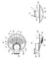
図1及び図2に示すように本例のヘアキャッチャー1は床パン3から流れ込んだ排水を受ける排水受部27で主体を構成してあり、排水受部27は厚みが薄く平面視円形の皿状をしている。図2(a)に示すように排水受部27は、片側半部(図2(a)に示す境界線aよりも右側の部分)を多数の排水用孔28を形成した排水部29とすると共に、他側半部(図2(a)に示す境界線aよりも左側の部分)には上方に向けて突出する円管状のオーバーフロー管部30を形成している。オーバーフロー管部30はヘアキャッチャー1の排水部29に形成した排水用孔28が毛髪等で目詰まりした場合に排水を通過させる流路を構成する。オーバーフロー管部30は排水受部27の他側半部の中央に位置し、オーバーフロー管部30を挟んだ他側半部の両側部分は排水部29へと排水を誘導する誘導部31a、31bとなり、各誘導部31a、31bは排水部29に連続して排水部29と両側の誘導部31a、31bとで平面視で三日月状をなす。また、ヘアキャッチャー1は平面視でその中心(排水受部27の中心)とオーバーフロー管部30の中心を通過する中心線bを中心にして線対称に形成してあり、各誘導部31a、31bの上面の面積は同じである。   As shown in FIGS. 1 and 2, the hair catcher 1 of this example is mainly composed of a drain receiving portion 27 that receives drainage flowing from the floor pan 3, and the drain receiving portion 27 is thin and has a circular dish in plan view. It has a shape. As shown in FIG. 2 (a), the drainage receiving portion 27 is a drainage portion 29 in which one side half (the portion on the right side of the boundary line a shown in FIG. 2 (a)) is formed with a number of drainage holes 28. At the same time, a circular overflow pipe portion 30 protruding upward is formed in the other half (the portion on the left side of the boundary line a shown in FIG. 2A). The overflow pipe part 30 constitutes a flow path through which waste water passes when the drain hole 28 formed in the drain part 29 of the hair catcher 1 is clogged with hair or the like. The overflow pipe part 30 is located at the center of the other half of the drainage receiving part 27, and both side parts of the other half part sandwiching the overflow pipe part 30 serve as guide parts 31a and 31b for guiding drainage to the drainage part 29. Each of the guide portions 31a and 31b is formed in a crescent shape in plan view with the drainage portion 29 and the guide portions 31a and 31b on both sides continuous to the drainage portion 29. The hair catcher 1 is formed symmetrically about a center line b passing through the center (center of the drainage receiving portion 27) and the center of the overflow pipe portion 30 in plan view, and the guide portions 31a and 31b. The area of the upper surface of is the same.

各誘導部31a、31bは排水部側に向かうに従って徐々に傾斜角が大きくなるよう下向きに傾斜しており、水勾配を設けている。また各誘導部31a、31bには排水用の孔を形成しておらず、非開口としている。さらに各誘導部31a、31bの表面の水滴滑落角を20度以下としている。このため、排水部29と反対側からヘアキャッチャー1に流れ込んだ排水は各誘導部31a、31bによって排水部29側にスムーズに誘導される。なお、上記各誘導部31a、31bの表面の水滴滑落角を20度以下とする手段としては表面をシリコン樹脂でコーティングすることが挙げられるが、これに限定されるものではない。また、上記水滴滑落角とは材料表面に滴下した水滴が滑落する材料表面の最低傾斜角度であり、上記又は以下の説明における水滴滑落角測定時の水滴の体積は0.03mlとする。   Each guide part 31a, 31b is inclined downward so that the inclination angle gradually increases toward the drainage part, and a water gradient is provided. In addition, drain holes are not formed in the guide portions 31a and 31b and are not opened. Further, the water drop sliding angle on the surface of each guiding portion 31a, 31b is set to 20 degrees or less. For this reason, the waste water that has flowed into the hair catcher 1 from the side opposite to the drainage portion 29 is smoothly guided to the drainage portion 29 side by the guide portions 31a and 31b. In addition, as a means to make the water drop sliding angle of the surface of each said guidance | induction part 31a, 31b below 20 degree | times, although coating the surface with a silicone resin is mentioned, it is not limited to this. The water drop sliding angle is the minimum inclination angle of the material surface on which the water drop dropped on the material surface slides, and the volume of the water drop at the time of measuring the water drop sliding angle in the above or the following description is 0.03 ml.

排水部29の最下部は水平な底部32で構成してあり、該底部32はオーバーフロー管部30に対向する箇所に位置する。排水部29の底部32を除く部分は底部32に向かって滑らかに下り傾斜し、ここにも水勾配を設けている。即ち排水受部27には最下部に位置する排水部29の底部32に向かって周囲の全方向から水勾配が設けられている。また、排水部29の底部32と排水受部の周縁部を構成する環状の鍔状部33の排水部29側の半部とを接続する部分は各誘導部31a、31bの水勾配よりも急な水勾配となった急勾配部34としてあり、排水部29においては急勾配部34を除いた全面に亘って多数の排水用孔28を形成している。   The lowermost part of the drainage part 29 is constituted by a horizontal bottom part 32, and the bottom part 32 is located at a location facing the overflow pipe part 30. A portion of the drainage portion 29 excluding the bottom portion 32 is smoothly inclined downward toward the bottom portion 32, and a water gradient is also provided here. That is, the drainage receiving portion 27 is provided with a water gradient from all the surrounding directions toward the bottom portion 32 of the drainage portion 29 located at the lowermost portion. Further, the portion connecting the bottom portion 32 of the drainage portion 29 and the half portion on the drainage portion 29 side of the annular bowl-shaped portion 33 constituting the peripheral portion of the drainage receiving portion is steeper than the water gradient of each of the guide portions 31a and 31b. The drain portion 29 has a large number of drain holes 28 extending over the entire surface except for the steep portion 34.

また、上記排水部29は表面に水分を含んだ毛髪等が付着し難くなるように表面の水接触角(静止時)を90度以上(好ましくは100度以上)としてあり、撥水性を高めている。なお、排水部29の表面の水接触角を90度以上とする手段としては、排水部29全体をテフロン(登録商標、ポリ四フッ化エチレン)などの表面の水接触角が90度以上となる材料で形成しても良いし、樹脂にシリコンやフッ素などの撥水性分を配合して排水部29を成形しても良いし、表面にシリコン樹脂やフッ素樹脂をコーティングしても良い。   Further, the drainage part 29 has a surface water contact angle (at rest) of 90 degrees or more (preferably 100 degrees or more) so as to make it difficult for hair containing moisture to adhere to the surface, thereby improving water repellency. Yes. As a means for setting the water contact angle of the surface of the drainage part 29 to 90 degrees or more, the water contact angle of the surface of the drainage part 29 as a whole such as Teflon (registered trademark, polytetrafluoroethylene) becomes 90 degrees or more. The drainage part 29 may be formed by blending a water-repellent component such as silicon or fluorine into the resin, or the surface may be coated with a silicon resin or a fluororesin.

排水受部27の外周部から突出したオーバーフロー管部30の上端部からは排水部29と反対側に向かって横片状の摘み部35を突出しており、該摘み部35を突出したオーバーフロー管部30で取手部36を構成している。即ち、オーバーフロー管部30は取手部36の立上部37を構成する。摘み部35の先端部は排水受部27よりも外側に突出し、図3のようにヘアキャッチャー1を設置した状態ではオーバーフロー管部30が排水孔2よりも上方に突出して、摘み部35が排水孔2の上方に位置する。このためヘアキャッチャー1の手入れの際には上方に突出した取手部36の摘み部35を指で摘んでヘアキャッチャー1を容易に排水孔2から出し入れできる。   From the upper end portion of the overflow pipe portion 30 protruding from the outer peripheral portion of the drainage receiving portion 27, a horizontal piece-like knob portion 35 protrudes toward the opposite side of the drainage portion 29, and the overflow pipe portion protruding from the knob portion 35 The handle portion 36 is constituted by 30. That is, the overflow pipe part 30 constitutes a rising part 37 of the handle part 36. The tip of the knob portion 35 protrudes outward from the drainage receiving portion 27, and in the state where the hair catcher 1 is installed as shown in FIG. 3, the overflow pipe portion 30 protrudes above the drainage hole 2 and the knob portion 35 is drained. Located above the hole 2. For this reason, when the hair catcher 1 is cared for, the hair catcher 1 can be easily taken in and out of the drain hole 2 by picking the knob 35 of the handle portion 36 protruding upward with a finger.

上記ヘアキャッチャー1は例えば排水受部27の外周縁を構成する環状の鍔状部33から突出した係合突部42を排水孔2を構成する取付用筒体10の内周面に形成した係合溝(図示せず)に係合することで排水孔2に着脱自在に取付けられる。なお、ヘアキャッチャー1の設置状態における向きは限定されるものではなく、偏心位置にあるオーバーフロー管部30が浴槽側や洗い場側に配置されるように設置したり、また浴槽側を前方、洗い場側を後方とした場合に、ヘアキャッチャー1のオーバーフロー管部30が左右方向の片側に配置されるように設置しても良く、また、ヘアキャッチャー1は排水孔2の周縁部上に単に載置するだけであっても良い。   In the hair catcher 1, for example, an engagement protrusion 42 that protrudes from an annular flange 33 that forms the outer peripheral edge of the drain receiving portion 27 is formed on the inner peripheral surface of the mounting cylinder 10 that forms the drain hole 2. It is detachably attached to the drain hole 2 by engaging with a mating groove (not shown). In addition, the direction in the installation state of the hair catcher 1 is not limited, It installs so that the overflow pipe part 30 in an eccentric position may be arrange | positioned at the bathtub side or the washroom side, and the bathtub side is the front, the washroom side May be installed so that the overflow pipe portion 30 of the hair catcher 1 is arranged on one side in the left-right direction, and the hair catcher 1 is simply placed on the peripheral edge of the drain hole 2. May be just.

上記設置されたヘアキャッチャー1には前述のように床パン3からの排水が通過するが、この際、排水は排水カバー14の流水用隙間25及び排水孔2の周縁部上を経てヘアキャッチャー1の外側から排水受部27に流入し、この後、排水部29に形成した多数の排水用孔28から下流側に排出される。   As described above, the drainage from the floor pan 3 passes through the installed hair catcher 1. At this time, the drainage passes through the gap 25 for running water of the drainage cover 14 and the peripheral portion of the drainage hole 2. It flows into the drain receiving part 27 from the outside, and is then discharged downstream from a number of drain holes 28 formed in the drain part 29.

ここで、本例のヘアキャッチャー1の排水受部27は、複数の排水用孔28を形成した排水部29と、該排水部29へと排水を誘導する誘導部31a、31bを備え、誘導部31a、31bを非開口としているので、上記の排水時においては、ヘアキャッチャー1の排水受部27で受けられた排水は各誘導部31a、31bにより排水部29側にスムーズに誘導され、この排水部29に形成した多数の排水用孔28を介して排水がなされる。このため毛髪等は排水用孔28を設けた排水部29上にまとまって堆積することとなり、各誘導部31a、31bには毛髪等がたまり難くなる。従って、ヘアキャッチャー1の手入れの際には排水部29上の一箇所にまとまって堆積した毛髪等を取り除けば良く、手入れが容易になる。また、この毛髪等が堆積する排水部29の表面の水接触角は90度以上となっているので、水分を含んだ毛髪等の排水部29の表面に対する付着力を低減でき、排水部29上の毛髪等をより簡単に取り除くことできる。また、本例のヘアキャッチャー1にあっては排水受部27からは取手部36を突出しているため、手入れの際に裏返したヘアキャッチャー1の取手部36の摘み部35を指で摘んで振ることができ、この時には前述したように排水部29に一箇所にかたまりとなって堆積した毛髪等を簡単に振り落とすことができ、毛髪等を直接指で摘むなどすることなく簡単且つ清潔に手入れができる。   Here, the drainage receiving portion 27 of the hair catcher 1 of the present example includes a drainage portion 29 in which a plurality of drainage holes 28 are formed, and guide portions 31 a and 31 b that guide drainage to the drainage portion 29. Since the 31a and 31b are not opened, the drainage received by the drainage receiving portion 27 of the hair catcher 1 is smoothly guided to the drainage portion 29 side by the guiding portions 31a and 31b during the drainage. Drainage is performed through a number of drain holes 28 formed in the portion 29. For this reason, hair etc. will accumulate on the drainage part 29 which provided the hole 28 for drainage, and it will become difficult to collect hair etc. in each induction | guidance | derivation part 31a, 31b. Therefore, when the hair catcher 1 is cared for, it is only necessary to remove the hair, etc., collected in one place on the drainage part 29, and the care is facilitated. Moreover, since the water contact angle of the surface of the drainage part 29 on which the hair or the like is deposited is 90 degrees or more, the adhesion force to the surface of the drainage part 29 such as hair containing moisture can be reduced. It is possible to remove the hair etc. more easily. Moreover, in the hair catcher 1 of this example, since the handle part 36 protrudes from the drainage receiving part 27, the knob part 35 of the handle part 36 of the hair catcher 1 turned over at the time of maintenance is picked and shaken. At this time, as described above, the hair accumulated in one place on the drainage portion 29 can be easily shaken off, and it can be easily and cleanly maintained without directly picking the hair with a finger. Can do.

次に他例のヘアキャッチャー1について説明する。なお、以下の説明では図1及び図2に示す一例のヘアキャッチャー1と同一の構成については同一の番号を付与し、重複する説明は省略する。   Next, another example of the hair catcher 1 will be described. In the following explanation, the same number is given about the same composition as hair catcher 1 of an example shown in Drawing 1 and Drawing 2, and duplicate explanation is omitted.

図4に示す本例のヘアキャッチャー1の各誘導部31a、31bには複数の通水孔43を形成してあり、各誘導部31a、31bの通水孔43からも排水を行えるようにしてある。また各誘導部31a、31bに形成した通水孔43は排水部29に形成した排水用孔28よりも小径であり、また単位面積当たりの数も少なく、通水孔43の開口面積を合計した各誘導部31a、31bにおける開口面積は排水用孔28の開口面積を合計した排水部29における開口面積よりも小さく、これにより各誘導部31a、31bにおける排水効率は排水部29の排水効率よりも低くなっている。なお、本例においても、先の一例と同じく排水部29の表面の水接触角を90度以上とし、各誘導部31a、31bの表面の水滴滑落角(水滴滑落角測定時の水滴は0.03mlとする)を20度以下としている。   A plurality of water passage holes 43 are formed in each of the guiding portions 31a and 31b of the hair catcher 1 of this example shown in FIG. 4 so that drainage can also be performed from the water passing holes 43 of the respective guiding portions 31a and 31b. is there. Further, the water passage holes 43 formed in each of the guiding portions 31a and 31b have a smaller diameter than the water drain holes 28 formed in the drainage portion 29, and the number per unit area is small, and the opening areas of the water passage holes 43 are totaled. The opening area in each guiding part 31a, 31b is smaller than the opening area in the draining part 29, which is the sum of the opening areas of the draining holes 28, whereby the draining efficiency in each guiding part 31a, 31b is more than the draining efficiency of the draining part 29. It is low. Also in this example, the water contact angle on the surface of the drainage part 29 is set to 90 degrees or more as in the previous example, and the water drop sliding angle on the surface of each guiding part 31a, 31b (the water drop at the time of measuring the water drop sliding angle is 0. 0). 03 ml) is set to 20 degrees or less.

このように各誘導部31a、31bにおける排水効率を排水部29の排水効率よりも低くして、各誘導部31a、31bにおける排水量を排水部29における排水量よりも少なくすることでも、ヘアキャッチャー1の排水受部27で受けられた排水を各誘導部31a、31bにより排水部29側にスムーズに誘導でき、毛髪等を排水用孔28を設けた排水部29上にまとまって堆積させることができる。   Thus, even if the drainage efficiency in each induction | guidance | derivation part 31a, 31b is made lower than the drainage efficiency of the drainage part 29, and the drainage amount in each guidance | induction part 31a, 31b is made smaller than the drainage amount in the drainage part 29, the hair catcher 1 of FIG. The drainage received by the drainage receiving portion 27 can be smoothly guided to the drainage portion 29 side by the respective guiding portions 31a and 31b, and hair or the like can be accumulated and accumulated on the drainage portion 29 provided with the drainage holes 28.

次に更に他例のヘアキャッチャー1について説明する。なお、以下の説明では図1及び図2に示す一例のヘアキャッチャー1と同一の構成については同一の番号を付与し、重複する説明は省略する。   Next, another example of the hair catcher 1 will be described. In the following explanation, the same number is given about the same composition as hair catcher 1 of an example shown in Drawing 1 and Drawing 2, and duplicate explanation is omitted.

図5に示すように本例のヘアキャッチャー1は円形皿状の排水受部27を中央の排水部29と外周部の誘導部31cとで構成してあり、誘導部31cは排水部29を囲む環状に形成されている。なお、本例のヘアキャッチャー1にはオーバーフロー管部30を設けていない。   As shown in FIG. 5, the hair catcher 1 of this example includes a circular dish-shaped drainage receiving portion 27 including a central drainage portion 29 and an outer peripheral guide portion 31 c, and the guide portion 31 c surrounds the drainage portion 29. It is formed in an annular shape. In addition, the overflow pipe part 30 is not provided in the hair catcher 1 of this example.

排水部29は水平で排水受部27の底部を構成するものであって、該排水部29には一例と同様に多数の排水用孔28を形成してあり、また表面の水接触角を90度以上としている。誘導部31cは非開口であり、外周縁から中央の排水部29側に向かって下り傾斜する水勾配がつけられている。また誘導部31cの表面の水滴滑落角(水滴滑落角測定時の水滴は0.03mlとする)は一例と同様に20度以下としている。   The drainage part 29 is horizontal and constitutes the bottom part of the drainage receiving part 27. The drainage part 29 is formed with a number of drainage holes 28 as in the example, and the water contact angle on the surface is 90. It ’s over. The guiding portion 31c is not open and has a water gradient that is inclined downward from the outer peripheral edge toward the central drainage portion 29 side. Further, the water drop sliding angle on the surface of the guiding portion 31c (the water drop at the time of measuring the water drop sliding angle is 0.03 ml) is set to 20 degrees or less as in the example.

なお、図示は省略するが、上記誘導部31cには図4に示す他例のヘアキャッチャー1における誘導部31a、31bと同様に誘導部31cの排水効率が排水部29の排水効率よりも低くなるように小径の通水孔を形成しても良いものとする。また、上記誘導部31cは排水部29側に向かうに従って傾斜角が小さくなるよう下向きに傾斜しているが、図6に示すように誘導部31cを断面で内側に突となる弧状とし、排水部29側に向かうに従って傾斜角が大きくなるよう下向きに傾斜させても良く、この場合は、誘導部31cに毛髪が留まることを一層防止できる。   In addition, although illustration is abbreviate | omitted, the drainage efficiency of the guidance | induction part 31c becomes lower than the drainage efficiency of the drainage part 29 similarly to the guidance | induction parts 31a and 31b in the hair catcher 1 of the other example shown in FIG. Thus, a small-diameter water passage hole may be formed. Further, the guide portion 31c is inclined downward so that the inclination angle becomes smaller toward the drainage portion 29 side. However, as shown in FIG. You may make it incline downward so that an inclination | tilt angle may become large as it goes to 29 side, In this case, it can prevent further that hair stays in the induction | guidance | derivation part 31c.

本発明の実施の形態の一例のヘアキャッチャーを示す斜視図である。It is a perspective view which shows the hair catcher of an example of embodiment of this invention. 同上のヘアキャッチャーを示し、(a)は平面図、(b)は側面図、(c)は背面図である。The hair catcher same as the above is shown, (a) is a plan view, (b) is a side view, and (c) is a rear view. 同上のヘアキャッチャーを排水孔に設置した状態を示す断面図である。It is sectional drawing which shows the state which installed the hair catcher same as the above in the drain hole. 他例のヘアキャッチャーの平面図である。It is a top view of the hair catcher of other examples. 更に他例のヘアキャッチャーを示し、(a)は平面図であり、(b)は正面図である。Furthermore, the hair catcher of another example is shown, (a) is a top view, (b) is a front view. 更に他例のヘアキャッチャーの正面図である。Furthermore, it is a front view of the hair catcher of another example.

符号の説明Explanation of symbols

1 ヘアキャッチャー
27 排水受部
28 排水用孔
29 排水部
31a〜31c 誘導部
43 通水孔
DESCRIPTION OF SYMBOLS 1 Hair catcher 27 Drain receiving part 28 Drain hole 29 Drain part 31a-31c Guide part 43 Water flow hole

Claims (2)

複数の排水用孔を形成した排水部と、該排水部に連続して設けられて排水部へと排水を誘導する誘導部とを有する排水受部を備え、該排水受部の片側半部を前記排水部とし、該排水受部の他側半部に上方に向けて突出するオーバーフロー管部を突設すると共に該他側半部におけるオーバーフロー管部の両側に前記誘導部を設け、前記誘導部を非開口又は排水用の通水孔は形成されるが排水部よりも排水効率の低いものとし、前記排水部の表面の水接触角を90度以上とし、前記誘導部が排水部側に向かうに従って傾斜角が大きくなるよう下向きに傾斜して成ることを特徴とするヘアキャッチャー。 A drainage receiving portion having a drainage portion in which a plurality of drainage holes are formed , and a guiding portion that is provided continuously to the drainage portion and guides drainage to the drainage portion, and has a half on one side of the drainage receiving portion. The drainage portion is provided with an overflow pipe portion projecting upward on the other half portion of the drainage receiving portion, and the guide portions are provided on both sides of the overflow pipe portion in the other half portion, The part is not opened or drainage water holes are formed, but drainage efficiency is lower than the drainage part, the water contact angle of the surface of the drainage part is 90 degrees or more, and the guide part is on the drainage part side A hair catcher characterized by being inclined downward so that the inclination angle increases as it goes. 前記誘導部の表面の水滴滑落角(水滴滑落角測定時の水滴は0.03mlとする)を20度以下とすることを特徴とする請求項1に記載のヘアキャッチャー。   The hair catcher according to claim 1, wherein a water drop sliding angle on the surface of the guiding portion (a water drop at the time of measuring a water drop sliding angle is 0.03 ml) is 20 degrees or less.
JP2007195238A 2007-07-26 2007-07-26 Hair catcher Expired - Fee Related JP4894666B2 (en)

Priority Applications (1)

Application Number Priority Date Filing Date Title
JP2007195238A JP4894666B2 (en) 2007-07-26 2007-07-26 Hair catcher

Applications Claiming Priority (1)

Application Number Priority Date Filing Date Title
JP2007195238A JP4894666B2 (en) 2007-07-26 2007-07-26 Hair catcher

Publications (2)

Publication Number Publication Date
JP2009030333A JP2009030333A (en) 2009-02-12
JP4894666B2 true JP4894666B2 (en) 2012-03-14

Family

ID=40401134

Family Applications (1)

Application Number Title Priority Date Filing Date
JP2007195238A Expired - Fee Related JP4894666B2 (en) 2007-07-26 2007-07-26 Hair catcher

Country Status (1)

Country Link
JP (1) JP4894666B2 (en)

Families Citing this family (3)

* Cited by examiner, † Cited by third party
Publication number Priority date Publication date Assignee Title
JP5712478B2 (en) * 2009-09-17 2015-05-07 株式会社ノーリツ Drainage basket
JP6232242B2 (en) * 2013-10-08 2017-11-15 株式会社フジワラテクノアート Heat treatment device
CN104594461A (en) * 2015-02-06 2015-05-06 成都陶玛斯卫浴有限责任公司 Washing device capable of preventing articles from falling

Family Cites Families (7)

* Cited by examiner, † Cited by third party
Publication number Priority date Publication date Assignee Title
JP2001161575A (en) * 1999-12-10 2001-06-19 Toto Ltd Counter top board
JP4635268B2 (en) * 2000-09-21 2011-02-23 サンウエーブ工業株式会社 Eye plate
JP2004083816A (en) * 2002-08-29 2004-03-18 Kansai Paint Co Ltd Aerosol composition and method for forming water-slipping film by using the same
JP4104404B2 (en) * 2002-09-12 2008-06-18 日本曹達株式会社 A slime remover for bathroom drains with a fixed eye plate.
JP3915772B2 (en) * 2003-11-11 2007-05-16 松下電工株式会社 Hair catcher
JP4512888B2 (en) * 2004-06-17 2010-07-28 パナソニック電工株式会社 Bathroom drainage equipment
JP4895760B2 (en) * 2006-01-16 2012-03-14 株式会社Lixil Hair catcher

Also Published As

Publication number Publication date
JP2009030333A (en) 2009-02-12

Similar Documents

Publication Publication Date Title
JP5387194B2 (en) Draining eye plate
JP2009030333A (en) Hair catcher
JP4840267B2 (en) Hair catcher
JP4837684B2 (en) Hair catcher
JP2015214809A (en) Hair catcher
JP5703824B2 (en) Drain trap
JP5446123B2 (en) Drain trap
JP5330842B2 (en) Hair catcher
JP5319900B2 (en) Hair catcher
JP2008025105A (en) Hair catcher and bathroom unit having it
JP4512888B2 (en) Bathroom drainage equipment
JP2009150111A (en) Hair catcher and bathroom unit having hair catcher
JP5712478B2 (en) Drainage basket
JP4840266B2 (en) Hair catcher
JP2010275717A (en) Drain grating
JP2009030330A (en) Drainage structure
JP5573000B2 (en) Draining eye plate
JP4849664B2 (en) Drain trap
JP6454841B2 (en) Drainage structure with collecting member
JP5270881B2 (en) Hair catcher
JPS6014865Y2 (en) collective drain trap
JP2009185537A (en) Hair catcher and bathroom unit with this hair catcher
JP6586299B2 (en) Hair catcher
JP2013221377A (en) Catch basin of urinal, and urinal
JP5904451B2 (en) urinal

Legal Events

Date Code Title Description
A621 Written request for application examination

Free format text: JAPANESE INTERMEDIATE CODE: A621

Effective date: 20090525

RD04 Notification of resignation of power of attorney

Free format text: JAPANESE INTERMEDIATE CODE: A7424

Effective date: 20101028

A977 Report on retrieval

Free format text: JAPANESE INTERMEDIATE CODE: A971007

Effective date: 20110527

A131 Notification of reasons for refusal

Free format text: JAPANESE INTERMEDIATE CODE: A131

Effective date: 20110531

A521 Written amendment

Free format text: JAPANESE INTERMEDIATE CODE: A523

Effective date: 20110801

A131 Notification of reasons for refusal

Free format text: JAPANESE INTERMEDIATE CODE: A131

Effective date: 20110906

A521 Written amendment

Free format text: JAPANESE INTERMEDIATE CODE: A523

Effective date: 20111107

TRDD Decision of grant or rejection written
A01 Written decision to grant a patent or to grant a registration (utility model)

Free format text: JAPANESE INTERMEDIATE CODE: A01

Effective date: 20111129

A01 Written decision to grant a patent or to grant a registration (utility model)

Free format text: JAPANESE INTERMEDIATE CODE: A01

A61 First payment of annual fees (during grant procedure)

Free format text: JAPANESE INTERMEDIATE CODE: A61

Effective date: 20111212

R151 Written notification of patent or utility model registration

Ref document number: 4894666

Country of ref document: JP

Free format text: JAPANESE INTERMEDIATE CODE: R151

FPAY Renewal fee payment (event date is renewal date of database)

Free format text: PAYMENT UNTIL: 20150106

Year of fee payment: 3

LAPS Cancellation because of no payment of annual fees