JP4893777B2 - Recording apparatus, recording method, reproducing apparatus, reproducing method, and recording medium - Google Patents
Recording apparatus, recording method, reproducing apparatus, reproducing method, and recording medium Download PDFInfo
- Publication number
- JP4893777B2 JP4893777B2 JP2009114241A JP2009114241A JP4893777B2 JP 4893777 B2 JP4893777 B2 JP 4893777B2 JP 2009114241 A JP2009114241 A JP 2009114241A JP 2009114241 A JP2009114241 A JP 2009114241A JP 4893777 B2 JP4893777 B2 JP 4893777B2
- Authority
- JP
- Japan
- Prior art keywords
- error correction
- recording
- address
- recording medium
- version
- Prior art date
- Legal status (The legal status is an assumption and is not a legal conclusion. Google has not performed a legal analysis and makes no representation as to the accuracy of the status listed.)
- Expired - Fee Related
Links
Images


Classifications
-
- G—PHYSICS
- G11—INFORMATION STORAGE
- G11B—INFORMATION STORAGE BASED ON RELATIVE MOVEMENT BETWEEN RECORD CARRIER AND TRANSDUCER
- G11B20/00—Signal processing not specific to the method of recording or reproducing; Circuits therefor
- G11B20/10—Digital recording or reproducing
- G11B20/12—Formatting, e.g. arrangement of data block or words on the record carriers
-
- G—PHYSICS
- G11—INFORMATION STORAGE
- G11B—INFORMATION STORAGE BASED ON RELATIVE MOVEMENT BETWEEN RECORD CARRIER AND TRANSDUCER
- G11B7/00—Recording or reproducing by optical means, e.g. recording using a thermal beam of optical radiation by modifying optical properties or the physical structure, reproducing using an optical beam at lower power by sensing optical properties; Record carriers therefor
- G11B7/007—Arrangement of the information on the record carrier, e.g. form of tracks, actual track shape, e.g. wobbled, or cross-section, e.g. v-shaped; Sequential information structures, e.g. sectoring or header formats within a track
-
- G—PHYSICS
- G11—INFORMATION STORAGE
- G11B—INFORMATION STORAGE BASED ON RELATIVE MOVEMENT BETWEEN RECORD CARRIER AND TRANSDUCER
- G11B20/00—Signal processing not specific to the method of recording or reproducing; Circuits therefor
- G11B20/10—Digital recording or reproducing
- G11B20/12—Formatting, e.g. arrangement of data block or words on the record carriers
- G11B20/1217—Formatting, e.g. arrangement of data block or words on the record carriers on discs
-
- G—PHYSICS
- G11—INFORMATION STORAGE
- G11B—INFORMATION STORAGE BASED ON RELATIVE MOVEMENT BETWEEN RECORD CARRIER AND TRANSDUCER
- G11B7/00—Recording or reproducing by optical means, e.g. recording using a thermal beam of optical radiation by modifying optical properties or the physical structure, reproducing using an optical beam at lower power by sensing optical properties; Record carriers therefor
- G11B7/24—Record carriers characterised by shape, structure or physical properties, or by the selection of the material
- G11B7/26—Apparatus or processes specially adapted for the manufacture of record carriers
- G11B7/261—Preparing a master, e.g. exposing photoresist, electroforming
-
- G—PHYSICS
- G11—INFORMATION STORAGE
- G11B—INFORMATION STORAGE BASED ON RELATIVE MOVEMENT BETWEEN RECORD CARRIER AND TRANSDUCER
- G11B20/00—Signal processing not specific to the method of recording or reproducing; Circuits therefor
- G11B20/10—Digital recording or reproducing
- G11B20/18—Error detection or correction; Testing, e.g. of drop-outs
-
- G—PHYSICS
- G11—INFORMATION STORAGE
- G11B—INFORMATION STORAGE BASED ON RELATIVE MOVEMENT BETWEEN RECORD CARRIER AND TRANSDUCER
- G11B20/00—Signal processing not specific to the method of recording or reproducing; Circuits therefor
- G11B20/10—Digital recording or reproducing
- G11B20/12—Formatting, e.g. arrangement of data block or words on the record carriers
- G11B20/1217—Formatting, e.g. arrangement of data block or words on the record carriers on discs
- G11B2020/1218—Formatting, e.g. arrangement of data block or words on the record carriers on discs wherein the formatting concerns a specific area of the disc
- G11B2020/1222—ECC block, i.e. a block of error correction encoded symbols which includes all parity data needed for decoding
-
- G—PHYSICS
- G11—INFORMATION STORAGE
- G11B—INFORMATION STORAGE BASED ON RELATIVE MOVEMENT BETWEEN RECORD CARRIER AND TRANSDUCER
- G11B20/00—Signal processing not specific to the method of recording or reproducing; Circuits therefor
- G11B20/10—Digital recording or reproducing
- G11B20/12—Formatting, e.g. arrangement of data block or words on the record carriers
- G11B20/1217—Formatting, e.g. arrangement of data block or words on the record carriers on discs
- G11B2020/1218—Formatting, e.g. arrangement of data block or words on the record carriers on discs wherein the formatting concerns a specific area of the disc
- G11B2020/1227—Formatting, e.g. arrangement of data block or words on the record carriers on discs wherein the formatting concerns a specific area of the disc one layer of multilayer disc
-
- G—PHYSICS
- G11—INFORMATION STORAGE
- G11B—INFORMATION STORAGE BASED ON RELATIVE MOVEMENT BETWEEN RECORD CARRIER AND TRANSDUCER
- G11B20/00—Signal processing not specific to the method of recording or reproducing; Circuits therefor
- G11B20/10—Digital recording or reproducing
- G11B20/12—Formatting, e.g. arrangement of data block or words on the record carriers
- G11B20/1217—Formatting, e.g. arrangement of data block or words on the record carriers on discs
- G11B2020/1218—Formatting, e.g. arrangement of data block or words on the record carriers on discs wherein the formatting concerns a specific area of the disc
- G11B2020/1238—Formatting, e.g. arrangement of data block or words on the record carriers on discs wherein the formatting concerns a specific area of the disc track, i.e. the entire a spirally or concentrically arranged path on which the recording marks are located
- G11B2020/1239—Formatting, e.g. arrangement of data block or words on the record carriers on discs wherein the formatting concerns a specific area of the disc track, i.e. the entire a spirally or concentrically arranged path on which the recording marks are located the track being a pregroove, e.g. the wobbled track of a recordable optical disc
-
- G—PHYSICS
- G11—INFORMATION STORAGE
- G11B—INFORMATION STORAGE BASED ON RELATIVE MOVEMENT BETWEEN RECORD CARRIER AND TRANSDUCER
- G11B20/00—Signal processing not specific to the method of recording or reproducing; Circuits therefor
- G11B20/10—Digital recording or reproducing
- G11B20/12—Formatting, e.g. arrangement of data block or words on the record carriers
- G11B2020/1264—Formatting, e.g. arrangement of data block or words on the record carriers wherein the formatting concerns a specific kind of data
- G11B2020/1265—Control data, system data or management information, i.e. data used to access or process user data
- G11B2020/1267—Address data
- G11B2020/1268—Address in pregroove [ADIP] information
-
- G—PHYSICS
- G11—INFORMATION STORAGE
- G11B—INFORMATION STORAGE BASED ON RELATIVE MOVEMENT BETWEEN RECORD CARRIER AND TRANSDUCER
- G11B20/00—Signal processing not specific to the method of recording or reproducing; Circuits therefor
- G11B20/10—Digital recording or reproducing
- G11B20/12—Formatting, e.g. arrangement of data block or words on the record carriers
- G11B2020/1264—Formatting, e.g. arrangement of data block or words on the record carriers wherein the formatting concerns a specific kind of data
- G11B2020/1265—Control data, system data or management information, i.e. data used to access or process user data
- G11B2020/1267—Address data
- G11B2020/1271—Address data the address data being stored in a subcode, e.g. in the Q channel of a CD
- G11B2020/1272—Burst indicator subcode [BIS]
-
- G—PHYSICS
- G11—INFORMATION STORAGE
- G11B—INFORMATION STORAGE BASED ON RELATIVE MOVEMENT BETWEEN RECORD CARRIER AND TRANSDUCER
- G11B20/00—Signal processing not specific to the method of recording or reproducing; Circuits therefor
- G11B20/10—Digital recording or reproducing
- G11B20/12—Formatting, e.g. arrangement of data block or words on the record carriers
- G11B2020/1264—Formatting, e.g. arrangement of data block or words on the record carriers wherein the formatting concerns a specific kind of data
- G11B2020/1265—Control data, system data or management information, i.e. data used to access or process user data
- G11B2020/1278—Physical format specifications of the record carrier, e.g. compliance with a specific standard, recording density, number of layers, start of data zone or lead-out
-
- G—PHYSICS
- G11—INFORMATION STORAGE
- G11B—INFORMATION STORAGE BASED ON RELATIVE MOVEMENT BETWEEN RECORD CARRIER AND TRANSDUCER
- G11B20/00—Signal processing not specific to the method of recording or reproducing; Circuits therefor
- G11B20/10—Digital recording or reproducing
- G11B20/18—Error detection or correction; Testing, e.g. of drop-outs
- G11B20/1833—Error detection or correction; Testing, e.g. of drop-outs by adding special lists or symbols to the coded information
- G11B2020/1836—Error detection or correction; Testing, e.g. of drop-outs by adding special lists or symbols to the coded information using a Reed Solomon [RS] code
-
- G—PHYSICS
- G11—INFORMATION STORAGE
- G11B—INFORMATION STORAGE BASED ON RELATIVE MOVEMENT BETWEEN RECORD CARRIER AND TRANSDUCER
- G11B20/00—Signal processing not specific to the method of recording or reproducing; Circuits therefor
- G11B20/10—Digital recording or reproducing
- G11B20/18—Error detection or correction; Testing, e.g. of drop-outs
- G11B20/1833—Error detection or correction; Testing, e.g. of drop-outs by adding special lists or symbols to the coded information
- G11B2020/1846—Error detection or correction; Testing, e.g. of drop-outs by adding special lists or symbols to the coded information using a picket code, i.e. a code in which a long distance code [LDC] is arranged as an array and columns containing burst indicator subcode [BIS] are multiplexed for erasure decoding
-
- G—PHYSICS
- G11—INFORMATION STORAGE
- G11B—INFORMATION STORAGE BASED ON RELATIVE MOVEMENT BETWEEN RECORD CARRIER AND TRANSDUCER
- G11B2220/00—Record carriers by type
- G11B2220/20—Disc-shaped record carriers
- G11B2220/23—Disc-shaped record carriers characterised in that the disc has a specific layer structure
- G11B2220/235—Multilayer discs, i.e. multiple recording layers accessed from the same side
-
- G—PHYSICS
- G11—INFORMATION STORAGE
- G11B—INFORMATION STORAGE BASED ON RELATIVE MOVEMENT BETWEEN RECORD CARRIER AND TRANSDUCER
- G11B2220/00—Record carriers by type
- G11B2220/20—Disc-shaped record carriers
- G11B2220/25—Disc-shaped record carriers characterised in that the disc is based on a specific recording technology
- G11B2220/2537—Optical discs
- G11B2220/2541—Blu-ray discs; Blue laser DVR discs
-
- G—PHYSICS
- G11—INFORMATION STORAGE
- G11B—INFORMATION STORAGE BASED ON RELATIVE MOVEMENT BETWEEN RECORD CARRIER AND TRANSDUCER
- G11B2220/00—Record carriers by type
- G11B2220/20—Disc-shaped record carriers
- G11B2220/25—Disc-shaped record carriers characterised in that the disc is based on a specific recording technology
- G11B2220/2537—Optical discs
- G11B2220/2562—DVDs [digital versatile discs]; Digital video discs; MMCDs; HDCDs
-
- G—PHYSICS
- G11—INFORMATION STORAGE
- G11B—INFORMATION STORAGE BASED ON RELATIVE MOVEMENT BETWEEN RECORD CARRIER AND TRANSDUCER
- G11B27/00—Editing; Indexing; Addressing; Timing or synchronising; Monitoring; Measuring tape travel
- G11B27/10—Indexing; Addressing; Timing or synchronising; Measuring tape travel
- G11B27/19—Indexing; Addressing; Timing or synchronising; Measuring tape travel by using information detectable on the record carrier
- G11B27/28—Indexing; Addressing; Timing or synchronising; Measuring tape travel by using information detectable on the record carrier by using information signals recorded by the same method as the main recording
- G11B27/32—Indexing; Addressing; Timing or synchronising; Measuring tape travel by using information detectable on the record carrier by using information signals recorded by the same method as the main recording on separate auxiliary tracks of the same or an auxiliary record carrier
-
- G—PHYSICS
- G11—INFORMATION STORAGE
- G11B—INFORMATION STORAGE BASED ON RELATIVE MOVEMENT BETWEEN RECORD CARRIER AND TRANSDUCER
- G11B7/00—Recording or reproducing by optical means, e.g. recording using a thermal beam of optical radiation by modifying optical properties or the physical structure, reproducing using an optical beam at lower power by sensing optical properties; Record carriers therefor
- G11B7/24—Record carriers characterised by shape, structure or physical properties, or by the selection of the material
- G11B7/2407—Tracks or pits; Shape, structure or physical properties thereof
- G11B7/24073—Tracks
- G11B7/24082—Meandering
Description
本発明は、光ディスク等の記録媒体、およびその記録媒体に対応する記録装置、記録方法、再生装置、再生方法に関する。 The present invention relates to a recording medium such as an optical disc, and a recording apparatus, recording method, reproducing apparatus, and reproducing method corresponding to the recording medium.
デジタルデータを記録・再生する記録媒体として、例えばCD(Compact Disk),MD(Mini-Disk),DVD(Digital Versatile Disk)、ブルーレイディスク(Blu-ray Disc(登録商標))などの光ディスク(光磁気ディスクを含む)が知られている。
光ディスクとは、金属薄板をプラスチックで保護した円盤に、レーザ光を照射し、その反射光の変化で信号を読み取る記録メディアの総称である。
As recording media for recording / reproducing digital data, for example, optical discs (magneto-optical) such as CD (Compact Disk), MD (Mini-Disk), DVD (Digital Versatile Disk), Blu-ray Disc (Blu-ray Disc (registered trademark)) Including disk).
An optical disk is a generic term for recording media that irradiate laser light onto a disk in which a thin metal plate is protected with plastic, and read signals by changes in reflected light.
近年、ブルーレイディスクに見られるような高密度記録により著しい大容量化が実現されている。
現行のブルーレイディスクとしては、記録層が1層又は2層のものが知られており、約25GB(Giga Byte)又は約50GBの記録容量が実現され、ビデオコンテンツやアプリケーションプログラムの記録に利用されている。
ここでブルーレイディスクフォーマットにおいて高密度記録や多層構造等により、更なる大容量化が検討されている。
In recent years, a marked increase in capacity has been realized by high-density recording as found in Blu-ray Discs.
As current Blu-ray discs, one with two or more recording layers is known, and a recording capacity of about 25 GB (Giga Byte) or about 50 GB is realized and used for recording video contents and application programs. Yes.
Here, a further increase in capacity is being studied in the Blu-ray Disc format due to high-density recording, a multilayer structure, and the like.
ところが、現行バージョンのブルーレイディスク(以下「Ver1.0ディスク」ともいう)に対応して各種スペックが決められ、既に市販されているディスクドライブ装置(以下「Ver1.0ドライブ」ともいう)との間で問題が生ずるおそれがある。
例えば3層以上の多層構造などとされる新たなバージョンのブルーレイディスク(以下「Ver2.0ディスク」ともいう)が、将来的に市販されるようになると、ユーザサイドではVer2.0ディスクをVer1.0ドライブに装填することも起こりえる。
基本的には同一のブルーレイディスクフォーマットであるため、Ver2.0ディスクをVer1.0ドライブで記録又は再生が絶対に不可能というわけではない。しかし、Ver2.0ディスクを、高密度化や多層化により実現すると、Ver1.0ドライブが備えた各種スペックでは不十分となることが想定される。
すると、Ver2.0ディスクをVer1.0ドライブで記録再生する場合において、記録エラーや再生エラーの発生頻度が高くなる恐れがある。
However, various specifications have been determined corresponding to the current version of the Blu-ray Disc (hereinafter also referred to as “Ver1.0 disc”), and the disk drive device (hereinafter also referred to as “Ver1.0 drive”) already on the market. May cause problems.
For example, when a new version of a Blu-ray disc (hereinafter also referred to as a “Ver2.0 disc”) having a multi-layer structure of three or more layers, etc., will be commercially available in the future, the Ver2.0 disc is replaced with Ver1. It is possible to load the 0 drive.
Since they are basically the same Blu-ray disc format, it is not absolutely impossible to record or play back a Ver 2.0 disc with a Ver 1.0 drive. However, if the Ver2.0 disk is realized by increasing the density or the number of layers, it is assumed that the various specifications provided in the Ver1.0 drive are insufficient.
Then, when recording / reproducing a Ver 2.0 disc with a Ver 1.0 drive, there is a possibility that the frequency of occurrence of recording errors and reproduction errors increases.
本発明はこのような事情に鑑み、Ver2.0ディスクをVer1.0ドライブに装填しても、記録再生ができないようにするものである。つまり、中途半端に記録再生ができるよりは、Ver1.0ドライブに対するVer2.0ディスクの互換性が無いようにする。これによってユーザサイドでのブルーレイディスクシステムの使用性を逆に高める。 In view of such circumstances, the present invention prevents recording and reproduction even when a Ver2.0 disc is loaded in a Ver1.0 drive. In other words, the Ver2.0 disc is not compatible with the Ver1.0 drive, rather than being able to record / reproduce halfway. This in turn increases the usability of the Blu-ray disc system on the user side.
本発明の記録装置は、共にアドレス情報をエラー訂正符号化するデータフォーマットであり、再生時に共通のエラー訂正処理が採用される同一種別の記録媒体としての第1のバージョンと第2のバージョンが存在する記録媒体種別における、上記第2のバージョンとしての記録媒体に対応する記録装置である。そして、上記第1のバージョンに対する場合と共通のエラー訂正符号化処理で、アドレス情報をエラー訂正符号化するエラー訂正符号化部と、上記エラー訂正符号化部で得られるエラー訂正符号化データを、上記第2のバージョンの記録媒体に非対応の再生装置ではアドレス復号が不能となるように変形するエラー訂正符号化データ変形部と、上記エラー訂正符号化データ変形部から得られるアドレス情報を記録媒体に記録する記録部とを備える。
また上記エラー訂正符号化データ変形部は、上記エラー訂正符号化データの一部をビット反転する。
また上記エラー訂正符号化データ変形部は、上記エラー訂正符号化データの一部として、上記第2のバージョンの記録媒体に非対応の再生装置での再生時においてシンボルエラー訂正能力を超えるシンボル数の各シンボルについて、ビット反転する。
また上記エラー訂正符号化データ変形部において上記エラー訂正符号化データをビット反転する位置は、上記第2のバージョンの記録媒体に非対応の再生装置での再生時においてビットエラーが発生しても、アドレス復号が不能となる位置であるとする。
また上記記録部は、アドレス情報を含む変調信号に応じて蛇行させたウォブリンググルーブとしてアドレス情報を記録媒体に記録する。
また上記記録部は、アドレス情報をメインデータ内アドレスとして記録媒体に記録する。
本発明の記録方法は、上記エラー訂正符号化部の処理に相当するエラー訂正符号化ステップと、上記エラー訂正符号化データ変形部の処理に相当するエラー訂正符号化データ変形ステップと、上記記録部の処理に相当する記録ステップを行う。
The recording apparatus of the present invention is a data format in which address information is error-correction encoded, and there are a first version and a second version as recording media of the same type in which a common error correction process is adopted during reproduction. This is a recording apparatus corresponding to the recording medium as the second version in the recording medium type. An error correction encoding unit that performs error correction encoding of address information in an error correction encoding process common to the case of the first version, and error correction encoded data obtained by the error correction encoding unit, An error correction encoded data deforming unit that deforms so that address decoding is impossible in a playback device that is not compatible with the recording medium of the second version, and address information obtained from the error correction encoded data deforming unit is recorded on the recording medium And a recording unit for recording.
The error correction encoded data transformation unit bit-inverts a part of the error correction encoded data.
In addition, the error correction encoded data transformation unit has, as a part of the error correction encoded data, the number of symbols exceeding the symbol error correction capability at the time of reproduction on a reproduction device not compatible with the recording medium of the second version. Bit invert for each symbol.
In addition, the position where the error correction encoded data is bit-reversed in the error correction encoded data transformation unit is the same even if a bit error occurs during playback on a playback device not compatible with the recording medium of the second version. It is assumed that the address cannot be decoded.
The recording unit records the address information on the recording medium as a wobbling groove meandered according to the modulation signal including the address information.
The recording unit records the address information as a main data address on a recording medium.
The recording method of the present invention includes an error correction encoding step corresponding to the process of the error correction encoding unit, an error correction encoded data transformation step corresponding to the process of the error correction encoded data transformation unit, and the recording unit The recording step corresponding to the above process is performed.
本発明の再生装置は、共にアドレス情報をエラー訂正符号化するデータフォーマットであり、再生時に共通のエラー訂正処理が採用される同一種別の記録媒体としての第1のバージョンと第2のバージョンが存在する記録媒体種別における、上記第2のバージョンとしての記録媒体であり、アドレス情報が、上記第1のバージョンに対する場合と共通のエラー訂正符号化処理でアドレス情報がエラー訂正符号化され、さらにエラー訂正符号化データが、上記第2のバージョンの記録媒体に非対応の再生装置ではアドレス復号が不能となるように変形処理されて記録されている上記第2のバージョンの記録媒体に対応する再生装置である。
そして、上記第2のバージョンとしての記録媒体から情報の読み出しを行う読出部と、上記記録媒体から読み出されるアドレス情報のエラー訂正符号化データについて、上記変形処理に対応する復元処理を行い、上記変形処理前のエラー訂正符号化データを得るエラー訂正符号化データ復元部と、上記エラー訂正符号化データ復元部で復元処理されたエラー訂正符号化データについて、エラー訂正処理を行ってアドレス情報を復号するエラー訂正処理部とを備える。
また上記エラー訂正符号化データ復元部は、上記復元処理として、記録時の上記変形処理においてビット反転されたエラー訂正符号化データの一部をビット反転する。
本発明の再生方法は、上記読出部の処理に相当する読出ステップと、上記エラー訂正符号化データ復元部の処理に相当するエラー訂正符号化データ復元ステップと、上記エラー訂正処理部の処理に相当するエラー訂正処理ステップとを行う。
Both of the playback apparatuses of the present invention are data formats in which address information is subjected to error correction coding, and there are a first version and a second version as recording media of the same type in which a common error correction process is adopted during playback. The recording medium type is a recording medium as the second version, and the address information is subjected to error correction encoding by error correction encoding processing common to the case of the first version, and further error correction is performed. In the playback apparatus corresponding to the second version of the recording medium, the encoded data is recorded by being transformed so that the address decoding is impossible in the playback apparatus not compatible with the second version of the recording medium. is there.
Then, a reading unit that reads information from the recording medium as the second version, and error correction encoded data of the address information read from the recording medium, a restoration process corresponding to the deformation process is performed, and the deformation An error correction encoded data restoration unit that obtains error correction encoded data before processing, and error correction encoded data restored by the error correction encoded data restoration unit performs error correction processing and decodes address information And an error correction processing unit.
In addition, the error correction encoded data restoration unit bit-inverts part of the error correction encoded data bit-inverted in the deformation process at the time of recording as the restoration process.
The reproduction method of the present invention corresponds to a reading step corresponding to the process of the reading unit, an error correction encoded data restoring step corresponding to the process of the error correction encoded data restoring unit, and a process of the error correction processing unit. Error correction processing step.
本発明の記録媒体は、共にアドレス情報をエラー訂正符号化するデータフォーマットであり、再生時に共通のエラー訂正処理が採用される同一種別の記録媒体としての第1のバージョンと第2のバージョンが存在する記録媒体種別における、上記第2のバージョンとしての記録媒体であり、アドレス情報が、上記第1のバージョンに対する場合と共通のエラー訂正符号化処理でアドレス情報がエラー訂正符号化され、さらにエラー訂正符号化データが、上記第2のバージョンの記録媒体に非対応の再生装置ではアドレス復号が不能となるように変形処理されて記録されている記録媒体である。 Both of the recording media of the present invention are data formats for error correction encoding of address information, and there are a first version and a second version as recording media of the same type in which a common error correction process is adopted during reproduction. The recording medium type is a recording medium as the second version, and the address information is subjected to error correction encoding by error correction encoding processing common to the case of the first version, and further error correction is performed. This is a recording medium in which encoded data is recorded after being subjected to a modification process so that address decoding is impossible in a playback device that does not support the recording medium of the second version.
このような本発明では、第2のバージョンの記録媒体には、エラー訂正符号化されたアドレス情報が、第2のバージョンの記録媒体に非対応の再生装置ではアドレス復号が不能となるように変形処理されて記録されている。従って第2のバージョンの記録媒体は、非対応の再生装置(例えば第1のバージョンの記録媒体のみに対応して製造された再生装置)では、アドレスデコードができない。
つまり第1,第2のバージョンではエラー訂正符号化処理が共通であるが、エラー訂正符号化データが特定のビット反転等の変形処理によって、第2のバージョンの記録媒体に非対応の再生装置ではアドレスエラー訂正不能の状態に導かれ、アドレス復号不能となる。アドレス復号不能となることで、その非対応再生装置では、第2のバージョンの記録媒体が装填されてもアクセス不能(記録再生が不能)の状態とすることができる。
In the present invention, the second version of the recording medium is modified so that the error correction encoded address information cannot be decoded by a playback device that does not support the second version of the recording medium. Processed and recorded. Therefore, the second version of the recording medium cannot be address-decoded by an incompatible playback device (for example, a playback device manufactured only for the first version of the recording medium).
In other words, the error correction encoding process is common in the first and second versions, but the error correction encoded data is modified by a specific bit inversion process or the like in a playback device that is not compatible with the recording medium of the second version. The address error cannot be corrected and the address cannot be decoded. Since the address decoding becomes impossible, the incompatible playback device can be made inaccessible (recording / playback is impossible) even when the second version of the recording medium is loaded.
本発明によれば、本発明の記録媒体(第2のバージョンの記録媒体)は、共通のデータフォーマット、エラー訂正処理が採用される第1のバージョンの記録媒体のみに対応する従前の再生装置や記録装置では、アドレス復号不能の状態とし、記録再生不能とできる。これによって、同一種別の記録媒体でありながら、本発明の第2のバージョンの記録媒体のみについて従前の再生装置、記録装置であえて使用できないようにすることができ、不安定な動作状態が生ずることを回避できる。そのため、システム全体としての使用性が向上する。 According to the present invention, the recording medium of the present invention (second version recording medium) is a conventional playback device that supports only the first version recording medium that employs a common data format and error correction processing. In the recording device, the address cannot be decoded, and recording / reproduction cannot be performed. As a result, although the recording medium is of the same type, only the recording medium of the second version of the present invention can be prevented from being used by the conventional reproducing apparatus and recording apparatus, resulting in an unstable operation state. Can be avoided. Therefore, the usability of the entire system is improved.
以下、本発明の実施の形態を次の順序で説明する。
[1.ディスク]
[2.データ内アドレスの記録再生]
[3.ウォブルアドレスの記録再生]
[4.ディスクドライブ装置]
[5.マスタリング装置]
Hereinafter, embodiments of the present invention will be described in the following order.
[1. disk]
[2. Recording and playback of addresses in data]
[3. Recording and playback of wobble addresses]
[4. Disk drive device]
[5. Mastering device]
[1.ディスク]
まず実施の形態となるディスクにおける物理的な特性及びウォブリングトラックについて説明する。
本例の光ディスクは、ブルーレイディスクの範疇に属するものとする。実施の形態のブルーレイディスクは、現行のブルーレイディスクと同じく、アドレス情報をエラー訂正符号化するデータフォーマットを採用し、再生時に現行のブルーレイディスクに対するものと共通のエラー訂正処理が採用される。
なお以下では、先に述べたように現行のブルーレイディスクを「Ver1.0ディスク」、実施の形態のディスクに相当するブルーレイディスクを「Ver2.0ディスク」と呼ぶこととする。
また、従前のブルーレイディスクの記録装置、再生装置を「Ver1.0ドライブ」と呼ぶ。これに対応して、本実施の形態の記録装置/再生装置、即ちVer2.0ディスクに対応するディスクドライブ装置については「Ver2.0ドライブ」と呼ぶ場合もある。
[1. disk]
First, physical characteristics and a wobbling track in the disk according to the embodiment will be described.
The optical disc of this example belongs to the category of Blu-ray disc. Like the current Blu-ray disc, the Blu-ray disc of the embodiment adopts a data format for error-correction encoding of address information, and an error correction process common to that for the current Blu-ray disc is adopted during reproduction.
Hereinafter, as described above, the current Blu-ray disc is referred to as “Ver1.0 disc”, and the Blu-ray disc corresponding to the disc of the embodiment is referred to as “Ver2.0 disc”.
Also, a conventional Blu-ray disc recording device and playback device are referred to as “Ver1.0 drive”. Correspondingly, the recording / reproducing apparatus of the present embodiment, that is, the disk drive apparatus corresponding to the Ver2.0 disk may be referred to as “Ver2.0 drive”.
まず、ブルーレイディスクの基本的な物理構造やデータ構造について述べる。
ブルーレイディスクとしては、BD−ROMとして知られている再生専用タイプのものと、ユーザーデータが記録可能なタイプがある。
再生専用タイプのものは、いわゆるエンボスピット列により情報記録が行われる。
記録可能タイプのものは、色素膜変化記録方式、相変化記録方式が利用されることで、データが記録可能とされる。
色素膜変化記録方式はライトワンス記録方式とも呼ばれ、一度だけデータ記録が可能で書換不能であるためデータ保存用途などに好適とされる。一方、相変化記録方式は、データの書換が可能であり音楽、映像、ゲーム、アプリケーションプログラム等の各種コンテンツデータの記録を始めとして各種用途に利用される。
First, the basic physical structure and data structure of a Blu-ray disc will be described.
As a Blu-ray disc, there are a read-only type known as a BD-ROM and a type capable of recording user data.
In the reproduction-only type, information recording is performed by a so-called embossed pit train.
In the recordable type, data can be recorded by using a dye film change recording method and a phase change recording method.
The dye film change recording method is also called a write-once recording method, and can be recorded only once and cannot be rewritten. On the other hand, the phase change recording method can rewrite data and is used for various purposes including recording of various content data such as music, video, games, application programs and the like.
ブルーレイディスクのディスクサイズは、直径が120mmとされる。また、ディスク厚は1.2mmとなる。即ちこれらの点では外形的に見ればCD(Compact Disc)方式のディスクや、DVD(Digital Versatile Disc)方式のディスクと同様となる。
記録/再生のためのレーザ波長は405nmとされ、いわゆる青色レーザが用いられるものとなる。光学系のNAは0.85とされる。
エンボスピット列によって形成されるトラックや、色素変化マーク、相変化マーク(フェイズチェンジマーク)が記録されるグルーブトラックのトラックピッチは0.32μm、線密度0.12μmとされる。そしてユーザーデータ容量としては1層あたりで約23〜25GBを実現している。
The disc size of the Blu-ray disc is 120 mm in diameter. The disc thickness is 1.2 mm. In other words, these are the same as CD (Compact Disc) type discs and DVD (Digital Versatile Disc) type discs in terms of external appearance.
The laser wavelength for recording / reproducing is 405 nm, and so-called blue laser is used. The NA of the optical system is 0.85.
The track pitch of the track formed by the embossed pit row, the groove track on which the dye change mark and the phase change mark (phase change mark) are recorded is 0.32 μm and the linear density is 0.12 μm. The user data capacity is about 23 to 25 GB per layer.
色素膜変化記録方式、相変化記録方式などの記録可能なディスクに対してデータを記録するには、データトラックに対するトラッキングを行うための案内手段が必要になる。このために、プリグルーブとして予め溝(グルーブ)を形成し、そのグルーブもしくはランド(グルーブとグルーブに挟まれる断面台地状の部位)をデータトラックとすることが行われている。
またデータトラック上の所定の位置にデータを記録することができるようにアドレス情報を記録する必要もあるが、このアドレス情報は、グルーブをウォブリング(蛇行)させることで記録される。
In order to record data on a recordable disc such as a dye film change recording method and a phase change recording method, a guide means for tracking the data track is required. For this purpose, a groove is formed in advance as a pre-groove, and the groove or land (a section plate-like portion sandwiched between the groove and the groove) is used as a data track.
Further, it is necessary to record address information so that data can be recorded at a predetermined position on the data track, but this address information is recorded by wobbling (meandering) the groove.
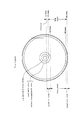
図1(a)に模式的に示すように、ディスク100上は、最内周側から最外周側までグルーブGVがスパイラル状に形成される。なお再生専用タイプの場合は、グルーブは形成されないが、このようにスパイラル状にエンボスピット列によるトラックが形成されることになる。
また、ディスクはCLV(線速度一定)方式で回転駆動されてデータの記録再生が行われるものとしているが、グルーブGVについてもCLVとされる。従って、トラック1周回のグルーブのウォブリング波数はディスク外周側に行くほど多くなる。
As schematically shown in FIG. 1A, on the
The disk is driven to rotate by the CLV (constant linear velocity) method to record and reproduce data, but the groove GV is also set to CLV. Therefore, the wobbling wave number of the groove per track increases as it goes to the outer periphery side of the disk.
このようなグルーブGVは、図1(b)に示すようにウォブリング(蛇行)されて形成されることにより物理アドレスが表現される。つまりグルーブGVの左右の側壁は、アドレス等に基づいて生成された信号に対応して蛇行している。
グルーブGVとその隣のグルーブGVの間はランドLとされ、上述のようにデータの記録はグルーブGVに行われる。つまりグルーブGVがデータトラックとなる。なお、ランドLをデータトラックとしてデータの記録をランドLに行うようにすることや、グルーブGVとランドLの両方をデータトラックとして用いることも考えられる。
Such a groove GV is formed by wobbling (meandering) as shown in FIG. 1B to express a physical address. That is, the left and right side walls of the groove GV meander corresponding to a signal generated based on an address or the like.
A land L is formed between the groove GV and the adjacent groove GV, and data is recorded in the groove GV as described above. That is, the groove GV becomes a data track. It is also conceivable to record data on the land L using the land L as a data track, or to use both the groove GV and the land L as data tracks.
このようにデータを記録するトラックがプリグループとして予め形成され、かつプリグループの側壁がアドレス情報に対応してウォブリングされていることで、記録時や再生時に、反射光情報として得られるウォブリング情報からアドレスを読み取ることができる。例えばアドレスを示すピットデータ等を予めトラック上に形成しておかなくても、所望の位置にアクセスしてデータを記録再生することができる。
なお、このようなウォブリングされたグルーブにより表現されるアドレス情報は、ATIP(Absolute Time In Pregroove)又はADIP(Adress In Pregroove)と呼ばれる。
In this way, tracks for recording data are formed in advance as a pre-group, and the side wall of the pre-group is wobbling corresponding to the address information, so that wobbling information obtained as reflected light information at the time of recording or reproduction can be used. The address can be read. For example, even if pit data indicating an address is not formed on a track in advance, a desired position can be accessed and data can be recorded and reproduced.
The address information expressed by such a wobbling groove is called ATIP (Absolute Time In Pregroove) or ADIP (Adress In Pregroove).
図2は、ディスク全体のレイアウト(領域構成)を示す。なお、図2は記録可能型のディスクの場合の例である。
ディスク上の領域としては、内周側からリードインゾーン、データゾーン、リードアウトゾーンが配される。
また、記録・再生に関する領域構成としてみれば。リードインゾーンの内周側がPBゾーン(再生専用領域)、リードインゾーンの外周側からリードアウトゾーンまでがRWゾーン(記録再生領域)とされる。
FIG. 2 shows the layout (area configuration) of the entire disc. FIG. 2 shows an example of a recordable disc.
As an area on the disc, a lead-in zone, a data zone, and a lead-out zone are arranged from the inner peripheral side.
If you look at the area structure related to recording and playback. The inner circumference side of the lead-in zone is a PB zone (reproduction-only area), and the outer circumference side of the lead-in zone to the lead-out zone is an RW zone (recording / reproduction area).
リードインゾーンは、半径24mmより内側に位置する。そして半径22.3〜23.1mmがプリレコーデッドデータゾーンとされる。
プリレコーデッドデータゾーンは、あらかじめコピープロテクションにつかう情報等(プリレコーデッド情報)を、ディスク上にスパイラル状に形成されたグルーブをウォブリングすることによって記録してある。これは書換不能な再生専用の情報であり、つまりプリレコーデッドデータゾーンが上記PBゾーン(再生専用領域)となる。
The lead-in zone is located inside a radius of 24 mm. A radius of 22.3 to 23.1 mm is set as a prerecorded data zone.
In the pre-recorded data zone, information used for copy protection (pre-recorded information) is recorded in advance by wobbling a groove formed in a spiral shape on the disk. This is reproduction-only information that cannot be rewritten, that is, the prerecorded data zone becomes the PB zone (reproduction-only area).
プリレコーデッドデータゾーンにおいてプリレコーデッド情報として例えばコピープロテクション情報が記録されるが、このコピープロテクション情報を用いて、例えば次のようなことが行われる。
本例にかかる光ディスクシステムでは、登録されたドライブ装置メーカー、ディスクメーカーがビジネスを行うことができ、その登録されたことを示す、メディアキー、あるいは、ドライブキーを有している。
ハックされた場合、そのドライブキー或いはメディアキーがコピープロテクション情報として記録される。このメディアキー、ドライブキーを有した、メディア或いはドライブは、この情報により、記録再生をすることをできなくすることができる。
For example, copy protection information is recorded as pre-recorded information in the pre-recorded data zone. For example, the following is performed using this copy protection information.
In the optical disc system according to this example, registered drive device manufacturers and disc manufacturers can conduct business, and have a media key or a drive key indicating that the registration has been performed.
When hacked, the drive key or media key is recorded as copy protection information. With this information, the medium or drive having the media key and the drive key can be made unrecordable.
リードインゾーンにおいて半径23.1〜24mmにはテストライトエリア及びディフェクトマネジメントエリアが設けられる。
テストライトエリアは記録/再生時のレーザパワー等、フェーズチェンジマークの記録再生条件を設定する際の試し書きなどにつかわれる。
ディフェクトマネジメントエリアはディスク上のディフェクト情報を管理する情報を記録再生する。
In the lead-in zone, a test write area and a defect management area are provided at a radius of 23.1 to 24 mm.
The test write area is used for test writing when setting recording / playback conditions for phase change marks such as laser power during recording / playback.
The defect management area records and reproduces information for managing defect information on the disc.
半径24.0〜58.0mmがデータゾーンとされる。データゾーンは、実際にユーザーデータがフェイズチェンジマークにより記録再生される領域である。
半径58.0〜58.5mmはリードアウトゾーンとされる。リードアウトゾーンは、リードインゾーンと同様のディフェクトマネジメントエリアが設けられたり、また、シークの際、オーバーランしてもよいようにバッファエリアとしてつかわれる。
半径23.1mm、つまりテストライトエリアから、リードアウトゾーンまでが、フェイズチェンジマークが記録再生されるRWゾーン(記録再生領域)とされる。
A radius of 24.0 to 58.0 mm is a data zone. The data zone is an area where user data is actually recorded and reproduced by phase change marks.
A radius of 58.0 to 58.5 mm is a lead-out zone. The lead-out zone is provided with a defect management area similar to the lead-in zone, and is used as a buffer area so that overrun may occur during seek.
A radius of 23.1 mm, that is, from the test write area to the lead-out zone is an RW zone (recording / reproducing area) where the phase change mark is recorded / reproduced.
以上は記録可能タイプのディスクの例であるが、再生専用タイプの場合も、リードインゾーン、データゾーン、リードアウトゾーンが配されることは同様である。但しテストライトエリア、ディフェクトマネジメントエリアは設けられず、またディスクの全範囲がエンボスピットによる再生専用領域となる。 The above is an example of a recordable type disc, but the lead-in zone, the data zone, and the lead-out zone are also arranged in the read-only type. However, the test write area and the defect management area are not provided, and the entire range of the disc is a reproduction-only area by the embossed pits.
続いて、主たるデータとして相変化マークやエンボスピット列等で記録されるデータ及びADIP情報としてトラックウォブリングにより記録されるデータのECC構造について図3,図4,図5により説明する。
なお、トラック上に相変化マーク、色素変化マーク、或いはエンボスピット列により記録される情報を「メインデータ」と呼び、またトラックウォブリングにより記録されるデータを「ウォブルデータ」と呼んで区別する。
Next, the ECC structure of data recorded as phase change marks and embossed pit strings as main data and data recorded as ADIP information by track wobbling will be described with reference to FIGS.
The information recorded by the phase change mark, the dye change mark, or the embossed pit string on the track is called “main data”, and the data recorded by the track wobbling is called “wobble data”.
まず図3には、メインデータ(ユーザーデータ)についてのECCフォーマットを示している。
ECC(エラー訂正コード)としては、メインデータ64KB(=1セクターの2048バイト×32セクター)に対するLDC(long distance code)と、BIS(Burst indicator subcode)の2つがある。
First, FIG. 3 shows an ECC format for main data (user data).
There are two types of ECC (Error Correction Code): LDC (long distance code) for
図3(a)に示すメインデータ64KBについては、図3(b)のようにECCエンコードされる。即ちメインデータは1セクタ2048Bについて4BのEDC(error detection code)を付加し、32セクタに対し、LDCを符号化する。LDCはRS(248,216,33)、符号長248、データ216、ディスタンス33のRS(reed solomon)コードである。304の符号語がある。
The
一方、BISは、図3(c)に示す720B(Byte)のデータに対して、図3(d)のようにECCエンコードされる。即ちRS(62,30,33)、符号長62、データ30、ディスタンス33のRS(reed solomon)コードである。24の符号語がある。
On the other hand, BIS is ECC-encoded as shown in FIG. 3D with respect to 720 B (Byte) data shown in FIG. That is, the RS (62, 30, 33),
図5(a)にメインデータについてのフレーム構造を示している。
上記LDCのデータと、BISは図示するフレーム構造を構成する。即ち1フレームにつき、データ(38B)、BIS(1B)、データ(38B)、BIS(1B)、データ(38B)が配されて155Bの構造となる。つまり1フレームは38B×4の152Bのデータと、38BごとにBISが1B挿入されて構成される。
フレームシンクFS(フレーム同期信号)は、1フレーム155Bの先頭に配される。1つのブロックには496のフレームがある。
LDCデータは、0,2,・・・の偶数番目の符号語が、0,2,・・・の偶数番目のフレームに位置し、1,3,・・・の奇数番目の符号語が、1,3,・・・の奇数番目のフレームに位置する。
FIG. 5A shows a frame structure for main data.
The LDC data and the BIS constitute the frame structure shown in the figure. That is, for each frame, data (38B), BIS (1B), data (38B), BIS (1B), and data (38B) are arranged to form a 155B structure. That is, one frame is configured by inserting 38B × 4 152B data and 1B of BIS for each 38B.
A frame sync FS (frame synchronization signal) is arranged at the head of one frame 155B. There are 496 frames in one block.
In the LDC data, even-numbered
BISはLDCの符号より訂正能力が非常に優れた符号をもちいており、ほぼ、すべて訂正される。つまり符号長62に対してディスタンスが33という符号を用いている。
このため、エラーが検出されたBISのシンボルは次のように使うことができる。
ECCのデコードの際、BISを先にデコードする。図5(a)のフレーム構造において隣接したBISあるいはフレームシンクFSの2つがエラーの場合、両者のあいだにはさまれたデータ38Bはバーストエラーとみなされる。このデータ38Bにはそれぞれエラーポインタが付加される。LDCではこのエラーポインタをつかって、ポインターイレージャ訂正をおこなう。
これによりLDCだけの訂正より、訂正能力を上げることができる。
BISにはアドレス情報等が含まれている。このアドレス情報は、ROMタイプディスク等で、ウォブリンググルーブによるアドレス情報がない場合等につかわれる。もちろん記録可能ディスクにおける再生時のアドレス取得にも使用できる。
The BIS uses a code having a much better correction capability than the LDC code, and almost all are corrected. That is, a code having a distance of 33 with respect to the
Therefore, the BIS symbol in which an error is detected can be used as follows.
When decoding ECC, BIS is decoded first. In the frame structure of FIG. 5A, when two adjacent BIS or frame sync FS are in error, the data 38B sandwiched between them is regarded as a burst error. An error pointer is added to each data 38B. The LDC uses this error pointer to correct the pointer erasure.
As a result, the correction capability can be improved as compared with correction using only LDC.
The BIS includes address information and the like. This address information is used when there is no address information by a wobbling groove on a ROM type disk or the like. Of course, it can also be used for address acquisition during playback on a recordable disc.
なお、最小記録単位となるRUB(recording unit block:記録再生クラスタ)は、図5(a)に示したメインデータのECCブロックの496フレームに、その前後に2フレームのPLL等のためのリンクエリアを付加した498フレームで構成される。 Note that the RUB (recording unit block: recording / playback cluster) serving as the minimum recording unit is the link area for the PLL of 2 frames before and after the 496 frames of the ECC block of the main data shown in FIG. Is composed of 498 frames.
次に図4にウォブルデータについてのECCフォーマットを示す。
この場合ECCには、データ4KB(1セクタ2048B×2セクタ)に対するLDC(long distance code)とBIS(Burst indicator subcode)の2つがある。
Next, FIG. 4 shows an ECC format for wobble data.
In this case, there are two ECCs, LDC (long distance code) and BIS (Burst indicator subcode) for
図4(a)に示すウォブルデータとしてのデータ4KBについては、図4(b)のようにECCエンコードされる。即ちデータは1セクタ2048Bについて4BのEDC(error detection code)を付加し、2セクタに対し、LDCを符号化する。LDCはRS(248,216,33)、符号長248、データ216、ディスタンス33のRS(reed solomon)コードである。19の符号語がある。
The data 4KB as wobble data shown in FIG. 4A is ECC-encoded as shown in FIG. 4B. In other words, 4B EDC (error detection code) is added to 1 sector 2048B, and LDC is encoded to 2 sectors. LDC is an RS (reed solomon) code of RS (248, 216, 33),
一方、BISは、図4(c)に示す120Bのデータに対して、図4(d)のようにECCエンコードされる。即ちRS(62,30,33)、符号長62、データ30、ディスタンス33のRS(reed solomon)コードである。4つの符号語がある。
On the other hand, the BIS is ECC-encoded as shown in FIG. 4D with respect to the 120B data shown in FIG. That is, the RS (62, 30, 33),
図5(b)にウォブルデータについてのフレーム構造を示している。
上記LDCのデータと、BISは図示するフレーム構造を構成する。即ち1フレームにつき、フレームシンクFS(1B)、データ(10B)、BIS(1B)、データ(9B)が配されて21Bの構造となる。つまり1フレームは19Bのデータと、BISが1B挿入されて構成される。
フレームシンクFS(フレーム同期信号)は、1フレームの先頭に配される。1つのブロックには248のフレームがある。
FIG. 5B shows a frame structure for wobble data.
The LDC data and the BIS constitute the frame structure shown in the figure. That is, for each frame, the frame sync FS (1B), data (10B), BIS (1B), and data (9B) are arranged to form a 21B structure. That is, one frame is configured by inserting 19B data and 1B BIS.
A frame sync FS (frame synchronization signal) is arranged at the head of one frame. There are 248 frames in one block.
この場合もBISはLDCの符号より訂正能力が非常に優れた符号をもちいており、ほぼ、すべて訂正される。このため、エラーが検出されたBISのシンボルは次のように使うことができる。
ECCのデコードの際、BISを先にデコードする。隣接したBIS或いはフレームシンクFSの2つがエラーの場合、両者のあいだにはさまれたデータ10B、あるいは9Bはバーストエラーとみなされる。このデータ10B、あるいは9Bにはそれぞれエラーポインタが付加される。LDCではこのエラーポインタをつかって、ポインターイレージャ訂正をおこなう。
これによりLDCだけの訂正より、訂正能力をあげることができる。
Also in this case, the BIS uses a code having a much better correction capability than the LDC code, and almost all are corrected. Therefore, the BIS symbol in which an error is detected can be used as follows.
When decoding ECC, BIS is decoded first. When two adjacent BISs or frame sync FSs are in error, the data 10B or 9B sandwiched between them is regarded as a burst error. An error pointer is added to each of the data 10B or 9B. The LDC uses this error pointer to correct the pointer erasure.
As a result, the correction capability can be improved rather than the correction only by the LDC.
図5,図6からわかるように、フェイズチェンジマークによるデータとプリレコーデッド情報は、ECCフォーマットとしては、同一の符号及び構造が採用される。
これは、プリレコーデッド情報のECCデコード処理は、フェイズチェンジマークによるデータ再生時のECCデコード処理を行う回路系で実行でき、ディスクドライブ装置としてはハードウエア構成の効率化を図ることができることを意味する。
As can be seen from FIGS. 5 and 6, the same code and structure are adopted as the ECC format for the data by the phase change mark and the pre-recorded information.
This means that ECC decoding processing of pre-recorded information can be executed by a circuit system that performs ECC decoding processing at the time of data reproduction by phase change marks, and the disk drive device can improve the efficiency of the hardware configuration. To do.
[2.データ内アドレスの記録再生]
本例のディスク(Ver2.0ディスク)におけるデータ内アドレスの記録再生について説明する。データ内アドレスとは、図3,図5(a)で述べたメインデータのECCブロック構造においてBISに含まれるアドレス情報のことである。
[2. Recording and playback of addresses in data]
The recording / reproduction of the in-data address on the disc of this example (Ver 2.0 disc) will be described. The in-data address is address information included in the BIS in the ECC block structure of the main data described with reference to FIGS.
図6(a)(b)は、Ver1.0ディスクと、Ver2.0ディスク(本実施の形態のディスク)におけるアドレスユニットナンバ(AUN)構造を示している。
まず図6(a)のように、Ver1.0ディスクは、4シンボル(1シンボル=8ビット)のAUNとしてAUN0〜AUN3で形成される。この4シンボルを、ビットA0〜A31で示している。
A0〜A4の5ビットは、クラスタ内ナンバである。クラスタは、データの記録単位である1つのRUB(recording unit block:記録再生クラスタ)を構成する単位である。
A5〜A23の19ビットは、クラスタアドレスとなる。
A24〜A26の3ビットはレイヤーナンバ(記録層のナンバ)となる。
A27〜A31はリザーブとされている。
FIGS. 6A and 6B show the address unit number (AUN) structure of the Ver1.0 disk and the Ver2.0 disk (the disk of the present embodiment).
First, as shown in FIG. 6A, a Ver1.0 disc is formed of AUN0 to AUN3 as AUN of 4 symbols (1 symbol = 8 bits). These four symbols are indicated by bits A0 to A31.
The five bits A0 to A4 are intra-cluster numbers. A cluster is a unit constituting one RUB (recording unit block) that is a data recording unit.
The 19 bits from A5 to A23 are a cluster address.
The three bits A24 to A26 are a layer number (recording layer number).
A27 to A31 are reserved.
これに対しVer2.0ディスクの場合は、AUN構造は図6(b)のようになる。
4シンボルのAUN0〜AUN3としてのビットA0〜A31において、A0〜A4の5ビットは、クラスタ内ナンバである。
A5〜A24の20ビットは、クラスタアドレスとなる。
A25〜A27の3ビットはレイヤーナンバとなる。
A28〜A31はリザーブとされている。
つまり、大容量化によって総クラスタ数が増えることに対応し、クラスタアドレスのビット数を20ビットにしている。
On the other hand, in the case of a Ver2.0 disc, the AUN structure is as shown in FIG.
In bits A0 to A31 as four symbols AUN0 to AUN3, five bits A0 to A4 are intra-cluster numbers.
The 20 bits A5 to A24 serve as a cluster address.
The 3 bits A25 to A27 are layer numbers.
A28 to A31 are reserved.
In other words, the number of bits of the cluster address is set to 20 bits in response to the increase in the total number of clusters due to the increase in capacity.
このようなアドレス情報のエラー訂正符号化(ECCエンコード)は、図7のアドレスユニット単位で行われる。
図7(a)では、それぞれ9バイトのアドレスユニットAU0〜AU15を示している。
アドレスユニットAU0は、アドレスフィールドAF0,0〜AF8,0で構成される。
アドレスユニットAU1は、アドレスフィールドAF0,1〜AF8,1で構成される。
同様にしてアドレスユニットAU15までがそれぞれ9バイトで構成される。
1つのアドレスフィールドAFは1バイト(1シンボル)である。
Such error correction encoding (ECC encoding) of address information is performed in units of address units in FIG.
FIG. 7A shows 9-byte address units AU0 to AU15, respectively.
The address unit AU0 is composed of address fields AF0,0 to AF8,0.
The address unit AU1 is composed of address fields AF0, 1 to AF8,1.
Similarly, the address units AU15 are each composed of 9 bytes.
One address field AF is one byte (one symbol).
この9バイトのアドレスユニット単位でECCエンコードが行われる。アドレスユニットAUは、図6に示したAUNとパリティを含む。
例えばアドレスユニットAU0を例に採ると、図7(b)のようになる。
アドレスユニットAU0のアドレスフィールドAF0,0、AF1,0、AF2,0、AF3,0については、アドレスユニットナンバAUN3,AUN2,AUN1,AUN0が、それぞれ割り当てられる。
アドレスフィールドAF4,0はフラグビットとされる。
アドレスフィールドAF5,0〜AF8,0には、パリティ(Parity3〜Parity0)が割り当てられる。
このアドレスユニット単位のECCエンコードによるエラー訂正は、9シンボル内に4シンボルのパリティを持つことで、2シンボル以内の誤りを訂正できる能力を持つことになる。
即ちアドレスユニットとして形成されるエラー訂正符号化データは、RS(9,5,5)、符号長9、データ5、ディスタンス5のRSコードである。
ECC encoding is performed in units of address units of 9 bytes. The address unit AU includes the AUN and parity shown in FIG.
For example, taking the address unit AU0 as an example, it is as shown in FIG.
Address unit numbers AUN3, AUN2, AUN1, and AUN0 are assigned to address fields AF0,0, AF1,0, AF2,0, AF3,0 of address unit AU0, respectively.
Address field AF4,0 is a flag bit.
Parities (
This error correction by ECC encoding in units of address units has the ability to correct errors within 2 symbols by having 4 symbols of parity within 9 symbols.
That is, the error correction encoded data formed as an address unit is RS (9, 5, 5),
図8に、メインデータブロック内のアドレスユニットの配置を示す。このメインデータブロックは図5(a)に示したものである。
496フレームのメインデータブロックにおいて、31フレーム単位でアドレスユニットがBISを用いて配置される。
1フレームにつきBISは3バイトあり、31フレームでは、BISは93バイトとなるが、そのうちの先頭の9バイトでアドレスユニットが配置される。残りのBISバイトにはコントロールデータ等が配置される。
図示のように、アドレスユニットAU0を構成するアドレスフィールドAF0,0〜AF8,0は、最初の31フレームにおいてBISの9バイトに配置される。
またアドレスユニットAU1を構成するアドレスフィールドAF0,1〜AF8,1は、2番目の31フレームにおけるBISの9バイトに配置される。
以降、同様にアドレスユニットAU2〜AU15が、同様に各31フレーム内のBISに配置される。
FIG. 8 shows the arrangement of address units in the main data block. This main data block is as shown in FIG.
In the main data block of 496 frames, address units are arranged using BIS in units of 31 frames.
There are 3 bytes of BIS per frame and BIS is 93 bytes in 31 frames, but the address unit is arranged in the first 9 bytes. Control data and the like are arranged in the remaining BIS bytes.
As shown in the figure, the address fields AF0,0 to AF8,0 constituting the address unit AU0 are arranged in 9 bytes of BIS in the first 31 frames.
The address fields AF0,1 to AF8,1 constituting the address unit AU1 are arranged in 9 bytes of BIS in the second 31 frames.
Thereafter, the address units AU2 to AU15 are similarly arranged in the BIS in each 31 frame.
上述したようにBISはエラー訂正能力は高いものであるが、アドレスユニットのエラー訂正については、アドレスユニット単位で行われる。これは迅速性が要求されるアドレスデコードに関しては、図3(d)のBISブロックを用いた訂正では間に合わないためである。
そのためアドレス情報の訂正能力はアドレスユニットAUの訂正能力に依存するものとなり、上述のように2シンボル以内の訂正が可能とされる。
換言すれば、3シンボル以上のエラーは訂正できないものとなる。さらに言えば、3シンボル以上のエラーを敢えて生じさせると、アドレスが復号できないことになる。
As described above, BIS has a high error correction capability, but error correction of address units is performed in units of address units. This is because the correction using the BIS block in FIG. 3D is not in time for address decoding that requires quickness.
Therefore, the correction capability of the address information depends on the correction capability of the address unit AU, and correction within two symbols is possible as described above.
In other words, an error of 3 symbols or more cannot be corrected. Furthermore, if an error of 3 symbols or more is generated, the address cannot be decoded.
本実施の形態では、Ver2.0ディスクは、Ver1.0ドライブにおいて記録再生ができないようにする。記録再生ができないようにするには、Ver1.0ドライブにおいてアドレスデコードができないようにすればよい。アドレス情報が復号できなければ、記録再生のためのアクセスができないためである。
そこで上記のようなアドレスユニットAUとしてECCエンコードされるアドレス情報の記録再生に関して次のような処理を行う。
In the present embodiment, the Ver2.0 disc cannot be recorded / reproduced by the Ver1.0 drive. In order to prevent recording / reproduction, it is only necessary to prevent address decoding in the Ver1.0 drive. This is because if the address information cannot be decoded, access for recording and reproduction cannot be performed.
Therefore, the following processing is performed for recording / reproducing address information that is ECC-encoded as the address unit AU as described above.
本例のVer2.0ディスクに対して情報を記録する際、まずアドレス情報のエラー訂正符号化については、Ver1.0ディスクと共通のエラー訂正符号化を行う。つまり図7に示したアドレスユニットAU単位のエラー訂正符号化である。
但し、そのままアドレス情報を図8のメインデータブロックのBISに割り当てていくのではなく、9シンボル(9個のアドレスフィールド)のアドレスユニットAUの一部を変形する。具体的には所定のシンボルにおいて全部又は一部のビットを反転させる。その上で、一部ビット反転されたエラー訂正符号化データ(アドレスユニット)を、図8のようにBISに割り当て、メインデータブロックを形成して記録する。
When information is recorded on the Ver2.0 disc of this example, first, error correction encoding of address information is performed in common with Ver1.0 disc. That is, the error correction encoding is performed in units of the address unit AU shown in FIG.
However, the address information is not directly assigned to the BIS of the main data block in FIG. 8, but a part of the address unit AU of 9 symbols (9 address fields) is modified. Specifically, all or some of the bits are inverted in a predetermined symbol. After that, error correction encoded data (address unit) partially inverted in bit is assigned to the BIS as shown in FIG. 8, and a main data block is formed and recorded.
一方、Ver2.0ディスクに対応するVer2.0ドライブ(本実施の形態の再生装置)では、上記の変形処理に対応するため、ビット反転による変形処理に対する復元処理を行う。例えば反転されたビット位置に対してさらにビット反転を行うことで、元のアドレスフィールドを復元する。そしてその復元されたアドレスフィールドによって構成されるアドレスユニットAU単位でのエラー訂正デコードを行うものである。 On the other hand, a Ver 2.0 drive (a playback apparatus according to the present embodiment) corresponding to a Ver 2.0 disc performs restoration processing for deformation processing by bit inversion in order to support the above deformation processing. For example, the original address field is restored by further performing bit inversion on the inverted bit position. Then, error correction decoding is performed in units of address units AU constituted by the restored address field.
図9に、本例のVer2.0ディスクに対する記録と、そのVer2.0ディスクに対して再生を行う場合のアドレス処理の流れを示す。
処理S1〜S6は、Ver2.0ディスクへのデータ記録までの流れを示している。
FIG. 9 shows the flow of address processing when recording is performed on the Ver2.0 disc of this example, and playback is performed on the Ver2.0 disc.
Processes S1 to S6 show the flow up to data recording on the Ver 2.0 disc.
処理S1として、記録すべきアドレスユニットナンバ(AUN0〜AUN3)及びフラグデータを発生させる。
処理S2として、ECCエンコードを行う。即ち処理S1で発生させたAUN0〜AUN3及びフラグデータの5シンボルに対して、4シンボルのパリティ(Parity0〜Parity3)を生成する。即ちアドレスユニットAUを形成するための9シンボルを得る。
処理S3として、シンボルの変形処理を行う。
ここでは、9シンボルのうちAUN0,AUN1,Parity3,Parity2の4シンボルについてビット反転処理を行うものとする。なおシンボルのビット反転とは、シンボルを形成する8ビット全てを反転させてもよいし、所定の一部ビットのみを反転させるものでもよい。
一方、AUN2,AUN3,フラグビット,Parity1,Parity0の5シンボルについては反転処理は行わない。
As process S1, an address unit number (AUN0 to AUN3) to be recorded and flag data are generated.
As process S2, ECC encoding is performed. That is, 4-symbol parity (
As processing S3, symbol transformation processing is performed.
Here, it is assumed that bit inversion processing is performed on four symbols of AUN0, AUN1, Parity3, and Parity2 among nine symbols. The symbol bit inversion may invert all 8 bits forming the symbol or invert only a predetermined part of bits.
On the other hand, the inversion process is not performed for five symbols AUN2, AUN3, flag bits, Parity1 and Parity0.
処理S3としてアドレスフィールド形成を行う。
即ち反転処理されたAUN0,AUN1,Parity3,Parity2と、反転処理されていないAUN2,AUN3,フラグビット,Parity1,Parity0を、図7(b)のようにアドレスフィールドAF0〜AF8に割り当て、図7(a)のようにアドレスユニットAUを形成していく。
As a process S3, an address field is formed.
That is, AUN0, AUN1, Parity3, Parity2 subjected to inversion processing, and AUN2, AUN3, flag bits, Parity1, Parity0 not subjected to inversion processing are assigned to address fields AF0 to AF8 as shown in FIG. The address unit AU is formed as in a).
処理S4として記録データ(変調データ)を形成するエンコードが行われる。ブルーレイディスクの場合、変調方式としてRLL(1,7)PP変調方式(RLL;Run Length Limited、PP:Parity preserve/Prohibit rmtr(repeated minimum transition runlength))が用いられる。
図7のアドレスユニットAU0〜AU15とされたアドレス情報は、図8のようなメインデータブロック内に配置される。そして該メインデータブロックを構成するデータストリームがRLL(1,7)PP変調される。
そして処理S6として、変調データに応じたレーザ発光が行われ,ディスク(Ver2.0ディスク)に対してデータ記録が行われる。
As processing S4, encoding for forming recording data (modulation data) is performed. In the case of a Blu-ray disc, an RLL (1, 7) PP modulation method (RLL: Run Length Limited, PP: Parity preserve / Prohibit rmtr (repeated minimum transition runlength)) is used as a modulation method.
The address information set as the address units AU0 to AU15 in FIG. 7 is arranged in the main data block as shown in FIG. The data stream constituting the main data block is RLL (1, 7) PP modulated.
In step S6, laser light emission is performed according to the modulation data, and data recording is performed on the disc (Ver 2.0 disc).
以上の処理S1〜S6が、本実施の形態のVer2.0ドライブ(記録装置)で行われる。
例えばディスクが記録可能タイプであれば、Ver2.0ドライブとしての記録装置における記録時に、以上のアドレスに関する処理が行われる。
また再生専用タイプのディスクを想定する場合は、以上のアドレスに関する処理が、ディスク原盤のマスタリング工程(後述)において行われることになる。その場合、後述するマスタリング装置が、本実施の形態のVer2.0ドライブとしての記録装置となる。
The above processes S1 to S6 are performed by the Ver 2.0 drive (recording apparatus) of the present embodiment.
For example, if the disc is a recordable type, the above-described processing relating to the address is performed at the time of recording in a recording device as a Ver 2.0 drive.
When a read-only type disk is assumed, the above-described processing relating to the address is performed in a mastering process (described later) of the master disk. In that case, a mastering device to be described later is a recording device as a Ver2.0 drive of the present embodiment.
処理S7〜S11は、以上の記録が行われたVer2.0ディスクを、Ver2.0ドライブ(本実施の形態の記録再生装置)で再生する場合のアドレス処理を示している。
Ver2.0ディスクから読み出された情報については、処理S7として復調が行われる。即ちRLL(1,7)PP変調データの復調である。
これによりアドレス情報に関しては、図7(a)のアドレスユニットAU0〜AU15を構成する各アドレスフィールドのデータが得られる。
Processes S7 to S11 show address processing when the Ver2.0 disc on which the above recording has been performed is reproduced by a Ver2.0 drive (recording / reproducing apparatus of the present embodiment).
The information read from the Ver2.0 disc is demodulated as processing S7. That is, demodulation of RLL (1, 7) PP modulated data.
As a result, with respect to the address information, data of each address field constituting the address units AU0 to AU15 in FIG. 7A is obtained.
但し、記録時の処理S3の変形処理により、所定のアドレスフィールドのデータはビット反転処理が施されている。
そこで処理S8として復元処理を行う。
ここでは、アドレスユニットAUを構成する9シンボルのうちAUN0,AUN1,Parity3,Parity2の4シンボルについてビット反転処理を行う。つまり処理S3で反転されたビットを、再度反転させて元のシンボル値を復元する。
一方、AUN2,AUN3,フラグビット,Parity1,Parity0の5シンボルについては処理S3で反転されていないため、ここでもビット反転処理は行わない。
この復元処理により、元のアドレスフィールドのデータが得られる。
However, the bit inversion process is performed on the data of the predetermined address field by the deformation process of the process S3 at the time of recording.
Therefore, restoration processing is performed as processing S8.
Here, bit inversion processing is performed on four symbols of AUN0, AUN1, Parity3, and Parity2 among the nine symbols constituting the address unit AU. That is, the original symbol value is restored by inverting again the bit inverted in the process S3.
On the other hand, since the five symbols AUN2, AUN3, flag bit, Parity1 and Parity0 are not inverted in the process S3, the bit inversion process is not performed here either.
By this restoration process, the original address field data is obtained.
処理S9でこの復元処理されたアドレスフィールドのデータとして、AUN0〜AUN3、フラグデータ、Parity0〜Parity3を得る。即ちアドレスユニットAUとしての9シンボルを得る。
処理S10で、アドレスユニットAUに対してエラー訂正デコードを行う。この場合、処理S8の復元によって、処理S2のECCエンコード時のアドレスユニットが復元されたものについてエラー訂正デコードが行われることになる。従って正常のエラー訂正デコードが行われ、処理S11として、アドレス情報(AUN0〜AUN3)が正しく復号されることになる。
In the process S9, AUN0 to AUN3, flag data, and Parity0 to Parity3 are obtained as the address field data restored. That is, 9 symbols are obtained as the address unit AU.
In step S10, error correction decoding is performed on the address unit AU. In this case, the error correction decoding is performed on the address unit restored in the ECC encoding of the process S2 by the restoration of the process S8. Accordingly, normal error correction decoding is performed, and the address information (AUN0 to AUN3) is correctly decoded as processing S11.
このようにVer2.0ドライブによっては、Ver2.0ディスクの再生時においてデータ内アドレスを適正に読み出すことができる。従って、データ内アドレスを用いて通常に再生アクセスや記録アクセスを行うことができ、適正な再生動作、記録動作が可能となる。 As described above, depending on the Ver2.0 drive, the address in the data can be properly read when the Ver2.0 disc is reproduced. Therefore, it is possible to perform normal reproduction access and recording access using the in-data address, and appropriate reproduction operation and recording operation are possible.
一方、処理S7→S12〜S14は、上記のアドレス記録が行われたVer2.0ディスクを、Ver1.0ドライブ(従前の再生装置)で再生する場合のアドレス処理を示している。
Ver2.0ディスクから読み出された情報については、処理S7として復調が行われる。即ちRLL(1,7)PP変調データの復調である。
On the other hand, processes S7 → S12 to S14 show address processing when the Ver2.0 disc on which the above address recording has been performed is played back by a Ver1.0 drive (former playback device).
The information read from the Ver2.0 disc is demodulated as processing S7. That is, demodulation of RLL (1, 7) PP modulated data.
これによりアドレス情報に関しては、処理S12として、図7(a)のアドレスユニットAU0〜AU15を構成する各アドレスフィールドのデータが得られる。
但し、記録時の処理S3の変形処理により、所定のアドレスフィールドのデータ(AUN0,AUN1,Parity3,Parity2に相当するアドレスフィールド)はビット反転処理が施されている。
この反転処理された各アドレスフィールドのデータが、そのまま次の処理S13のエラー訂正デコードに供される。
各アドレスユニットAUに対してエラー訂正デコードを行う際、アドレスユニットAUを構成するアドレスフィールドの一部のデータは、ECCエンコード(処理S2)時とは異なった値となっている。アドレスユニットAU0で言えば、AUN0,AUN1,Parity3,Parity2に相当するアドレスフィールドAF2,0、AF3,0、AF5,0、AF6,0はビット反転による変形処理がされたシンボル値となっている。
アドレスユニットAUは、上述のとおり2シンボル以下の誤り訂正能力を持つところ、この場合、4シンボルの誤りが発生した状態となっていることになる。
従ってエラー訂正結果は「DF」(Decord Failure:エラー訂正失敗)となる。
つまり処理S14として、アドレス情報(AUN0〜AUN3)は正しく復号できない。
As a result, regarding the address information, as processing S12, data of each address field constituting the address units AU0 to AU15 of FIG. 7A is obtained.
However, the data in a predetermined address field (address fields corresponding to AUN0, AUN1, Parity3, and Parity2) has been subjected to bit inversion processing by the deformation process of the process S3 at the time of recording.
The data in each address field that has been subjected to the inversion processing is directly used for error correction decoding in the next processing S13.
When error correction decoding is performed on each address unit AU, a part of the data in the address field constituting the address unit AU has a value different from that at the time of ECC encoding (processing S2). In the address unit AU0, the address fields AF2,0, AF3,0, AF5,0, AF6,0 corresponding to AUN0, AUN1, Parity3, and Parity2 are symbol values that have undergone transformation processing by bit inversion.
As described above, the address unit AU has an error correction capability of 2 symbols or less. In this case, an error of 4 symbols has occurred.
Therefore, the error correction result is “DF” (Decord Failure).
That is, as process S14, the address information (AUN0 to AUN3) cannot be correctly decoded.
このようにVer1.0ドライブによっては、Ver2.0ディスクの再生時においてデータ内アドレスを適正に読み出すことができない。従って、通常に再生アクセス、記録アクセスを行うことができず、エラー処理として再生動作、記録動作は開始されない。
換言すれば、Ver2.0ディスクを、Ver1.0ドライブで記録再生不能とすることができる。
再生専用タイプのVer2.0ディスクの場合は、グルーブが存在しないため、以上のようにデータ内アドレスを読出不能とすることで、Ver1.0ドライブによる再生を不能とできる。
記録可能タイプのVer2.0ディスクの場合は、データ内アドレスが読出不能であっても、ウォブルアドレスについて読み出せると記録再生が可能となってしまう。そのため次に述べるように、ウォブルアドレスについてもVer1.0ドライブでは読み出せないようにするものである。
As described above, some Ver1.0 drives cannot properly read the address in the data during the reproduction of the Ver2.0 disc. Accordingly, normal reproduction access and recording access cannot be performed, and the reproduction operation and recording operation are not started as error processing.
In other words, it is possible to make a Ver2.0 disc unrecordable / reproducible with a Ver1.0 drive.
In the case of a read-only type Ver2.0 disc, since there is no groove, reproduction by a Ver1.0 drive can be disabled by making the address in the data unreadable as described above.
In the case of a recordable type Ver2.0 disc, even if the in-data address cannot be read, recording and reproduction are possible if the wobble address can be read. Therefore, as described below, the wobble address cannot be read by the Ver1.0 drive.
なお、以上の図9の例では、処理S3としての変形処理で、アドレスユニットAUを構成する9シンボルの内で4シンボルについてビット反転をおこなった。本例の場合、アドレスユニットAUの訂正能力は、3シンボルエラー以上で訂正不能となるため、処理S3では少なくとも3シンボル以上、ビット反転処理を行えばよい。
また、例えば4シンボルをビット反転する場合において、その処理対象は、AUN0,AUN1,Parity3,Parity2に限られるものではない。但し、この例のように、アドレス情報で2シンボル、パリティで2シンボルとして偏りを無くしてビット反転させることが好適と考えられる。
もちろん4シンボルを反転処理する場合、アドレスで4シンボルを反転処理させる例や、フラグビットのシンボルを反転処理対象とする例なども考えられる。
In the example of FIG. 9 described above, the bit inversion is performed for 4 symbols among the 9 symbols constituting the address unit AU in the transformation process as the process S3. In the case of this example, the correction capability of the address unit AU becomes uncorrectable after 3 symbol errors or more, and therefore, in the process S3, bit inversion processing should be performed for at least 3 symbols or more.
For example, in the case of bit inversion of 4 symbols, the processing target is not limited to AUN0, AUN1, Parity3, and Parity2. However, as shown in this example, it is considered preferable to perform bit inversion with no bias as
Of course, when four symbols are inverted, an example in which four symbols are inverted by an address, an example in which a flag bit symbol is an inversion target, and the like can be considered.
またアドレス情報については下位シンボルをビット反転対象としていることも適切と考えられる。これは、アドレスをECCデコードしないドライブも存在し、そのようなドライブにおいてアドレスがインクリメントしないようになるため、エラーとできるためである。
もちろんアドレス情報の上位シンボルAUN2,AUN3を反転対象に加える例も考えられる。
For address information, it is considered appropriate to set the lower symbol as a bit inversion target. This is because there is a drive that does not ECC decode the address, and the address does not increment in such a drive, so that an error can occur.
Of course, an example in which the upper symbols AUN2 and AUN3 of the address information are added to the inversion target is also conceivable.
[3.ウォブルアドレスの記録再生]
次に本例のディスク(Ver2.0ディスク)におけるウォブルアドレスの記録再生について説明する。
[3. Recording and playback of wobble addresses]
Next, recording / reproduction of wobble addresses on the disc of this example (Ver 2.0 disc) will be described.
図10(a)(b)は、Ver1.0ディスクと、Ver2.0ディスク(本実施の形態のディスク)におけるウォブルアドレス構造を示している。
まず図10(a)のように、Ver1.0ディスクは、ウォブルアドレスはビットA0〜A23で示す24ビットで構成される。なお、ウォブルアドレスは4ビットを1シンボルとして扱うが、4ビットシンボルを以下、ニブル(Nibble)と呼ぶ。24ビットのウォブルアドレスは6ニブルとなる。
A0、A1の2ビットは、クラスタ内ナンバである。
A2〜A20の19ビットは、クラスタアドレスとなる。
A21〜A23の3ビットはレイヤーナンバとなる。
FIGS. 10A and 10B show the wobble address structure in the Ver1.0 disk and the Ver2.0 disk (the disk of the present embodiment).
First, as shown in FIG. 10A, a Ver1.0 disk is composed of 24 bits indicated by bits A0 to A23. The wobble address handles 4 bits as one symbol, but the 4-bit symbol is hereinafter referred to as a nibble. A 24-bit wobble address is 6 nibbles.
The two bits A0 and A1 are intra-cluster numbers.
The 19 bits from A2 to A20 are cluster addresses.
The 3 bits A21 to A23 are layer numbers.
これに対しVer2.0ディスクの場合は、ウォブルアドレス構造は図10(b)のようになる。
6ニブルのビットA0〜A23において、A0,A1の2ビットは、クラスタ内ナンバである。
A2〜A21の21ビットは、クラスタアドレスとなる。大容量化によって総クラスタ数が増えることに対応し、クラスタアドレスのビット数を20ビットにしている。
A22〜A23の2ビットはレイヤーナンバとなる。
On the other hand, in the case of a Ver 2.0 disc, the wobble address structure is as shown in FIG.
In 6 nibble bits A0 to A23, 2 bits A0 and A1 are intra-cluster numbers.
The 21 bits of A2 to A21 are cluster addresses. Corresponding to the increase in the total number of clusters due to the increase in capacity, the number of bits of the cluster address is set to 20 bits.
Two bits A22 to A23 are layer numbers.
本例の場合、データの記録単位である1つのRUB(recording unit block:記録再生クラスタ)に対しては、ADIPアドレスとして3つのアドレスが入るものとされる。
図11にその様子を示す。RUB(記録再生クラスタ)は、図5(a)に示したデータのECCブロックの496フレームに、その前後に2フレームのPLL等のためのリンクエリアを付加した498フレームとして記録再生の単位である。
そして図11(a)のように1つのRUBに相当する区間において、ADIPとしては3つのアドレスブロックが含まれることになる。
1つのアドレスブロックは83ビットから形成される。
In the case of this example, one RUB (recording unit block: recording / reproducing cluster) which is a data recording unit is assumed to have three addresses as ADIP addresses.
This is shown in FIG. The RUB (recording / reproducing cluster) is a unit of recording / reproducing as 498 frames obtained by adding a link area for two frames of PLL or the like to the 496 frames of the ECC block of the data shown in FIG. .
In the section corresponding to one RUB as shown in FIG. 11 (a), three address blocks are included as ADIP.
One address block is formed from 83 bits.
図11(b)に1つのアドレスブロックの構成を示している。83ビットのアドレスブロックは、8ビットのシンクパート(同期信号パート)と、75ビットのデータパートからなる。
シンクパートの8ビットでは、モノトーンビット(1ビット)とシンクビット(1ビット)によるシンクブロックが4単位形成される。
データパートの75ビットでは、モノトーンビット(1ビット)とADIPビット(4ビット)によるADIPブロックが15単位形成される。
モノトーンビット、シンクビット、及びADIPビットは、それぞれ56ウォブル期間のウォブルで形成される。これらのビットの先頭にはビットシンクの為のMSK(minimam shift keying)マークが配される。
そしてモノトーンビットはMSKマークに続いて、キャリア周波数によるウォブルが連続して形成される。シンクビット及びADIPビットは、MSKマークに続いて、MSK変調波形及びSTW(saw tooth wobble)変調波形によるウォブルを有して形成される。
アドレス情報としては、データパートのADIPビット(4ビット)×15の60ビットを用いて記録される。
FIG. 11B shows the configuration of one address block. The 83-bit address block is composed of an 8-bit sync part (synchronization signal part) and a 75-bit data part.
In the 8 bits of the sync part, 4 units of sync blocks are formed by monotone bits (1 bit) and sync bits (1 bit).
In the 75 bits of the data part, 15 units of ADIP blocks are formed by monotone bits (1 bit) and ADIP bits (4 bits).
The monotone bit, the sync bit, and the ADIP bit are each formed by 56 wobble periods. An MSK (minimum shift keying) mark for bit sync is arranged at the head of these bits.
In the monotone bit, a wobble with a carrier frequency is continuously formed following the MSK mark. The sync bit and the ADIP bit are formed with an MSK mark followed by a wobble with an MSK modulation waveform and an STW (saw tooth wobble) modulation waveform.
The address information is recorded using 60 bits of ADIP bits (4 bits) × 15 of the data part.
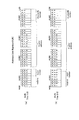
この60ビットで形成されるアドレスフォーマット(エラー訂正ブロック構造)は図12のようになる。アドレスデータとしてのECC単位は、このように合計60ビットの単位とされ、図示するようにNibble0〜Nibble14の15ニブル(1ニブル=4ビット)で構成される。このエラー訂正ブロック構造はデータが9ニブル(=36ビット)あり、これに対してパリティが6ニブル(=24ビット)付加される。 The address format (error correction block structure) formed of 60 bits is as shown in FIG. The ECC unit as address data is thus a unit of 60 bits in total, and is composed of 15 nibbles (1 nibble = 4 bits) of Nibble0 to Nibble14 as shown. In this error correction block structure, data has 9 nibbles (= 36 bits), and parity is added with 6 nibbles (= 24 bits).
9ニブル(36ビット)のデータにおいては、Nibble0〜Nibble5の6ニブル(24ビット)がADIPアドレス情報、つまり図10に示した24ビットのウォブルアドレスに用いられる。
Nibble6〜Nibble8の3ニブル(12ビット)が記録再生レーザパワー等の記録条件を記録したdisc ID等、AUXデータに用いられる。
Nibble9〜Nibble14の24ビットはパリティとされる。
エラー訂正方式としては4ビットを1ニブルとした、nibbleベースのリードソロモン符号RS(15,9,7)である。つまり、符号長15ニブル、データ9ニブル、パリティ6ニブルである。
In 9 nibble (36 bits) data, 6 nibbles (24 bits) of Nibble0 to Nibble5 are used for ADIP address information, that is, the 24-bit wobble address shown in FIG.
Three nibbles (12 bits) of Nibble6 to Nibble8 are used for AUX data such as disc ID in which recording conditions such as recording / reproducing laser power are recorded.
The 24 bits from Nibble9 to Nibble14 are used as parity.
The error correction method is a nibble-based Reed-Solomon code RS (15, 9, 7) in which 4 bits are 1 nibble. That is, the code length is 15 nibbles, the data is 9 nibbles, and the parity is 6 nibbles.
Nibble0〜Nibble5については、図12においてレイヤアドレス3ビット、RUBナンバ(クラスタアドレス)20ビット、アドレスナンバ(クラスタ内アドレス)2ビットを示しているが、これは図10(a)のVer1.0ディスクの場合である。
図10(b)のVer2.0ディスクの場合は、この24ビットが、レイヤアドレス2ビット、RUBナンバ(クラスタアドレス)21ビット、アドレスナンバ(クラスタ内アドレス)2ビットとなる。
For Nibble0 to Nibble5, the
In the case of the Ver2.0 disc shown in FIG. 10B, these 24 bits are a
図13に、本例のVer2.0ディスクに対する記録と、そのVer2.0ディスクに対して再生を行う場合のアドレス処理の流れを示す。
処理S20〜S21は、Ver2.0ディスクへのウォブルアドレス記録までの流れを示している。なお、ここでいうウォブルアドレス記録とは、ディスク原盤に対するマスタリング工程において行われるウォブリンググルーブ形成の際のこととなる。従って、この場合の記録装置とはマスタリング装置となる。
FIG. 13 shows a flow of address processing in the case of recording on the Ver2.0 disc of this example and reproducing on the Ver2.0 disc.
Processes S20 to S21 show the flow up to recording the wobble address on the Ver2.0 disc. The wobble address recording here refers to the formation of the wobbling groove performed in the mastering process for the master disc. Therefore, the recording apparatus in this case is a mastering apparatus.
処理S20として、記録すべきアドレスデータを発生させる。つまり図10(b)のウォブルアドレスの24ビット(6ニブル)である。
処理S21として、ECCエンコードを行う。即ち処理S20で発生させた6ニブルのウォブルアドレスに対して、3ニブルのAUXデータ、6ニブルのパリティを生成する。即ち図12の構造のエラー訂正符号化データを得る。
In process S20, address data to be recorded is generated. That is, it is 24 bits (6 nibbles) of the wobble address of FIG.
As process S21, ECC encoding is performed. That is, 3 nibble AUX data and 6 nibble parity are generated for the 6 nibble wobble address generated in step S20. That is, error correction encoded data having the structure shown in FIG. 12 is obtained.
処理S22として、ニブルの変形処理を行う。
図12に示したようにエラー訂正符号化データは15ニブル(Nibble14〜Nibble0)となる。この15ニブルのうちの所定位置のニブルに対してビット反転処理を行う。なおニブルのビット反転とは、ニブルを形成する4ビット全てを反転させてもよいし、所定の一部ビットのみを反転させるものでもよい。
図13では、処理S22として「111100010000100」と図示している。
これは、「1」はビット反転処理を行うこと、「0」はビット反転処理を行わないことを示し、それを15個のニブルの各位置に対応して示している。
つまり「111100010000100」は15ニブル(Nibble14〜Nibble0)のそれぞれに対応して、ビット反転処理を行うか否かを表す。
この場合、「1」に対応するNibble14、Nibble13、Nibble12、Nibble11、Nibble7、Nibble2についてビット反転処理を行い、他のニブルについてはビット反転処理を行わないことを示す。
As a process S22, a nibble deformation process is performed.
As shown in FIG. 12, the error correction encoded data is 15 nibbles (Nibble14 to Nibble0). Bit inversion processing is performed on nibbles at predetermined positions in the 15 nibbles. The bit inversion of the nibble may invert all the 4 bits forming the nibble, or may invert only a part of predetermined bits.
In FIG. 13, “111100010000100” is illustrated as the process S22.
This means that “1” indicates that bit inversion processing is performed, and “0” indicates that bit inversion processing is not performed, which are shown corresponding to the positions of 15 nibbles.
That is, “111100010000100” represents whether or not to perform bit inversion processing corresponding to each of 15 nibbles (Nibble14 to Nibble0).
In this case, bit inversion processing is performed for Nibble14, Nibble13, Nibble12, Nibble11, Nibble7, and Nibble2 corresponding to “1”, and bit inversion processing is not performed for other nibbles.
処理S23としてディスクへの記録を行う。この場合、処理S22の後におけるADIP情報に基づいてマスタリング(ディスク原盤のカッティング)を行い、ディスク原盤へADIP情報の変調信号に基づいて蛇行されたウォブリンググルーブ形成(露光)を行う。
後述するが、その後、ディスク原盤の現像、スタンパの作成、スタンパを用いたディスクの製造が行われる。
製造されるディスクは、Ver2.0ディスクとしての記録可能型ディスクとなる。
In step S23, recording on the disk is performed. In this case, mastering (cutting of the disc master) is performed based on the ADIP information after the process S22, and wobbling grooves formed (exposure) are performed on the disc master based on the modulation signal of the ADIP information.
As will be described later, development of the master disc, creation of a stamper, and manufacture of the disc using the stamper are performed thereafter.
The manufactured disc is a recordable disc as a Ver 2.0 disc.
処理S24〜S26は、以上のようにウォブリンググルーブが形成されているVer2.0ディスクに対して、Ver2.0ドライブ(本実施の形態の記録再生装置)で記録又は再生する場合のアドレス処理を示している。 Processes S24 to S26 indicate address processing when recording or playback is performed with the Ver2.0 drive (recording / playback apparatus according to the present embodiment) on the Ver2.0 disk on which the wobbling groove is formed as described above. ing.
Ver2.0ディスクのウォブリンググルーブから読み出された情報については、処理S24として復元処理を行う。
マスタリング時の処理22の変形処理により、ADIP情報の所定ニブルのデータはビット反転処理が施されているためである。
ここでも処理S27として「111100010000100」と図示している。
上記同様に「1」はビット反転処理を行うこと、「0」はビット反転処理を行わないことを示し、それを15個のニブルの各位置に対応して示している。従って、処理S22と同じく、「1」に対応するNibble14、Nibble13、Nibble12、Nibble11、Nibble7、Nibble2についてビット反転処理を行い、他のニブルについてはビット反転処理を行わない。
すると、マスタリング時に処理S21のECCエンコードにより得られた時点でのエラー訂正符号化データとして、図12に示すADIP情報が得られることになる。
The information read from the wobbling groove of the Ver 2.0 disc is restored as process S24.
This is because the bit inversion process is performed on the data of the predetermined nibble of the ADIP information by the deformation process of the
Here, “111100010000100” is illustrated as the process S27.
Similarly to the above, “1” indicates that bit inversion processing is performed, and “0” indicates that bit inversion processing is not performed, which are shown corresponding to the positions of 15 nibbles. Accordingly, similarly to the processing S22, the bit inversion processing is performed for Nibble14, Nibble13, Nibble12, Nibble11, Nibble7, and Nibble2 corresponding to “1”, and the bit inversion processing is not performed for the other nibbles.
Then, the ADIP information shown in FIG. 12 is obtained as the error correction encoded data obtained at the time of the master encoding by the ECC encoding in the process S21.
処理S25で、ADIP情報(図12の60ビット単位のエラー訂正符号化データ)に対してエラー訂正デコードを行う。この場合、処理S24の復元によって、処理S21のECCエンコード時のADIP情報が対象としてエラー訂正デコードが行われるため、ウォブルアドレスの情報(図10(b)のA0〜A23)が正しく復号されることになる。 In process S25, error correction decoding is performed on the ADIP information (60-bit error correction encoded data in FIG. 12). In this case, since the error correction decoding is performed on the ADIP information at the time of ECC encoding of the processing S21 by the restoration of the processing S24, the wobble address information (A0 to A23 in FIG. 10B) is correctly decoded. become.
このようにVer2.0ドライブによっては、Ver2.0ディスクの記録又は再生時においてウォブルアドレスを適正に読み出すことができる。従って、ウォブルアドレスを用いて通常に再生アクセスや記録アクセスを行うことができ、適正な再生動作、記録動作が可能となる。 As described above, depending on the Ver2.0 drive, the wobble address can be properly read when recording or reproducing the Ver2.0 disc. Accordingly, it is possible to perform normal reproduction access and recording access using the wobble address, and appropriate reproduction operation and recording operation are possible.
一方、処理S27〜S29は、上記のようにウォブリンググルーブ形成が行われたVer2.0ディスクを、Ver1.0ドライブ(従前の記録再生装置)で記録再生する場合のアドレス処理を示している。 On the other hand, the processes S27 to S29 show the address process when the Ver2.0 disc on which the wobbling groove is formed as described above is recorded and reproduced by the Ver1.0 drive (former recording / reproducing apparatus).
Ver2.0ディスクのウォブリンググルーブから読み出された情報については、処理S27としてのビット反転処理が行われる。
但し、この処理は処理22の変形処理に対応した本例で言う「復元処理」ではなく、従前の記録再生装置で行われている処理である。
ウォブリンググルーブによるアドレス処理に関しては、マスタリング時及びウォブルアドレス読出時に、15ニブルのうち6ニブルを反転させる処理が行われている。
これは、例えばADIP情報が入力されないときなどとして、ECCデコード処理に入力されるADIP情報が全て「0」になると、誤ってエラー訂正OKとなる場合があり、これを回避するために行われているものである。
Ver1.0ディスクについては、図示のように15ニブルについて、「000000000111111」としての反転(Nibble5〜Nibble0の反転)が、マスタリング時及びウォブルアドレス読出時に行われている。
For the information read from the wobbling groove of the Ver2.0 disc, the bit inversion processing as processing S27 is performed.
However, this process is not the “restoration process” in the present example corresponding to the deformation process of the
As for address processing by the wobbling groove, processing for inverting 6 nibbles of 15 nibbles is performed during mastering and wobble address reading.
This is done to avoid error correction OK when all ADIP information input to the ECC decoding process becomes “0”, for example, when ADIP information is not input. It is what.
For the Ver1.0 disc, as shown in the figure, for 15 nibbles, inversion as “000000000111111” (inversion of Nibble5 to Nibble0) is performed during mastering and wobble address reading.
Ver1.0ドライブでは、ADIP情報デコード時に、処理S27としてこのような反転処理が行われる。そして、この反転処理されたADIP情報について、処理S28としてECCデコード処理される。
ここでVer2.0ディスクは、処理S22による変形処理で「111100010000100」のビット反転処理が行われている。
すると、ECCデコードに供されるADIP情報は、処理S22の「111100010000100」の反転処理と、処理27の「000000000111111」の反転処理が加わることになり、「111100010111011」の状態となる。
つまり処理S21でのECCエンコード時のADIP情報に対して、Nibble14、Nibble13、Nibble12、Nibble11、Nibble7、Nibble5、Nibble4、Nibble3、Nibble1、Nibble0が反転された状態である。
このようなADIP情報に対しては、エラー訂正デコードできず、エラー訂正結果は「DF」(Decord Failure:エラー訂正失敗)となる。
つまり処理S29として、ウォブルアドレス(A0〜A23)は正しく復号できない。
In the Ver1.0 drive, such inversion processing is performed as processing S27 when ADIP information is decoded. The inverted ADIP information is subjected to ECC decoding processing as step S28.
Here, the Ver 2.0 disc is subjected to the bit inversion processing of “111100010000100” in the deformation processing in step S22.
Then, the ADIP information used for ECC decoding is subjected to the inversion process of “111100010000100” in process S22 and the inversion process of “000000000111111” in process 27, and becomes the state of “111100010111011”.
That is, Nibble14, Nibble13, Nibble12, Nibble11, Nibble7, Nibble5, Nibble4, Nibble3, Nibble1, Nibble0 are inverted with respect to the ADIP information at the time of ECC encoding in the process S21.
Such ADIP information cannot be subjected to error correction decoding, and the error correction result is “DF” (Decord Failure).
That is, as process S29, the wobble addresses (A0 to A23) cannot be correctly decoded.
このようにVer1.0ドライブによっては、Ver2.0ディスクの記録/再生時においてウォブルアドレスを適正に読み出すことができない。従って、通常に再生アクセス、記録アクセスを行うことができず、エラー処理として再生動作、記録動作は開始されない。
換言すれば、Ver2.0ディスクを、Ver1.0ドライブで記録再生不能とすることができる。
Thus, some Ver1.0 drives cannot properly read the wobble address during recording / reproduction of a Ver2.0 disc. Accordingly, normal reproduction access and recording access cannot be performed, and the reproduction operation and recording operation are not started as error processing.
In other words, it is possible to make a Ver2.0 disc unrecordable / reproducible with a Ver1.0 drive.
なお上述したように、Ver1.0ドライブによっては、Ver2.0ディスクのデータ内アドレスについても読み出せない。
記録可能タイプのディスクの場合、メインデータ記録済であれば、ウォブルアドレスが読み出せなくとも、データ内アドレスによってアドレス読出が可能であれば、再生可能となることもあり得るが、ウォブルアドレスもデータ内アドレスも読み出せないようにすることにより、Ver1.0ドライブによって、記録可能タイプのVer2.0ディスクに対する記録再生を、完全に不能とすることができる。
As described above, some Ver1.0 drives cannot read data addresses in Ver2.0 discs.
In the case of a recordable type disc, if the main data has been recorded, even if the wobble address cannot be read, it may be reproducible if the address can be read by the address in the data. By preventing the internal address from being read, the Ver1.0 drive can completely disable recording / reproduction on a recordable type Ver2.0 disc.
ところで、処理S22の変形処理、処理S24の復元処理では、15ニブル(Nibble14〜Nibble0)のそれぞれに対して、「111100010000100」とする反転を行うものとした。
これは、Ver1.0ドライブにおいて、必ずエラー訂正失敗となるようにニブル反転位置を選んだものである。
By the way, in the transformation process of the process S22 and the restoration process of the process S24, the inversion of “111100010000100” is performed for each of the 15 nibbles (Nibble14 to Nibble0).
In this case, the nibble inversion position is selected so that the error correction always fails in the Ver1.0 drive.
再生時には、データは常に正しく再生されるものではなく、そもそもそのためエラー訂正が行われる。
すると、変形処理として敢えてビット反転させても、復号エラーによってビット反転されていない状態になってしまうことがある。これは、復号エラーの生じ方によっては、変形処理させたにもかかわらず、Ver1.0ドライブにおいてエラー訂正OKとなる可能性があるということになる。ビット反転による変形が、復号エラーによって修正されてしまう部分が生ずることによる。
At the time of reproduction, data is not always reproduced correctly, and error correction is performed in the first place.
Then, even if bit inversion is intentionally performed as a deformation process, there is a case where the bit is not inverted due to a decoding error. This means that, depending on how the decoding error occurs, there is a possibility that the error correction is OK in the Ver1.0 drive despite the deformation process. This is because the deformation caused by bit inversion is corrected by a decoding error.
このため復号エラーが生じたとしても、Ver1.0ドライブにおいて必ず復号エラーとなるような変形処理を適切に選定する必要がある。ウォブルアドレスの場合、ビット反転するニブルの位置が重要となる。 For this reason, even if a decoding error occurs, it is necessary to appropriately select a deformation process that always causes a decoding error in the Ver1.0 drive. In the case of a wobble address, the position of the nibble where the bit is inverted is important.
図12で述べたようにADIP情報は、nibbleベースのRS(15,9,7)であって、シンボルが9ニブル、パリティが6ニブルであり、3ニブル訂正可能である。
すると、3ニブルの復号エラーが生じたとしても、その場合にVer1.0ドライブにおいてDF(エラー訂正失敗)とできればよい。
つまり15ニブルに対する反転位置パターンとして、そのようなパターンを見つければよいことになる。
As described in FIG. 12, the ADIP information is nibble-based RS (15, 9, 7), the symbol is 9 nibbles, the parity is 6 nibbles, and 3 nibbles can be corrected.
Then, even if a decoding error of 3 nibbles occurs, it is only necessary to be able to make DF (error correction failure) in the Ver1.0 drive in that case.
That is, it is only necessary to find such a pattern as an inverted position pattern for 15 nibbles.
そこで反転位置の設定のため、15ニブルに対する反転パターンとして考え得る全てのパターンについて、全ての反転位置パターンでビット復号エラーが発生した場合、エラー訂正が失敗となるか否かを検証した。 Therefore, in order to set the inversion position, it was verified whether or not error correction failed when bit decoding errors occurred in all inversion position patterns for all patterns that could be considered as inversion patterns for 15 nibbles.
15ニブルの反転位置のそれぞれのうちで、1誤り(ビット復号エラー)が発生する場合は、誤り発生のパターンとしては15通りある。この1誤り発生の場合、15通りの全てにおいて、Ver1.0ドライブにおいてエラー訂正失敗とすることができる。
また2誤り発生は1575通りあるが、これも全てにおいて、エラー訂正失敗とすることができる。
ところが3誤り102375通りを検証すると、95717通りでエラー訂正失敗とできるが、残りの6658通りはエラー訂正OKとなる。つまり、エラー訂正失敗とできる確率が約95%に落ちてしまう。
また全誤り103965通りについては、97307通りがエラー訂正失敗となり、残りはエラー訂正OKとなってしまう。
When one error (bit decoding error) occurs in each of the 15 nibble inversion positions, there are 15 error occurrence patterns. In the case of this one error occurrence, error correction failure can be made in the Ver1.0 drive in all 15 ways.
There are 1,575 occurrences of two errors, but all of these can be considered as error correction failures.
However, if three error 102375 patterns are verified, 95717 patterns can be considered as error correction failures, but the remaining 6658 patterns are error correction OK. That is, the probability of error correction failure falls to about 95%.
As for all errors 103965, 97307 are error correction failures and the rest are error correction OK.
つまり3誤り以上が発生すると、確実にエラー訂正失敗とさせることが困難である。但し、通常はアドレスデコードでは、アドレス連続性検出が併用される。
例えば仮に、アドレス値として「00」→「01」→「02」・・・という連続性が判別されており、或るアドレス値がデコードされても、前後と連続性が無い場合はアドレスエラーとされる。例えば「00」→「01」→「85」のように非連続な値の場合、エラー訂正OKであっても、そのアドレス値「85」はエラーとされる。
結局、Ver1.0ドライブでも、アドレス連続性検出が併用されることが通常であるので、エラー訂正がOKとなっても、連続性検出結果でアドレスエラーとなればよい。
In other words, when three or more errors occur, it is difficult to reliably fail the error correction. However, address continuity detection is usually used in combination with address decoding.
For example, if the continuity of “00” → “01” → “02”... Is determined as the address value and there is no continuity before and after a certain address value is decoded, an address error is indicated. Is done. For example, in the case of non-continuous values such as “00” → “01” → “85”, even if error correction is OK, the address value “85” is regarded as an error.
In the end, address continuity detection is usually used together with a Ver1.0 drive. Therefore, even if error correction is OK, an address error may be generated as a result of continuity detection.
すると、15ニブルについて反転位置としては、最もエラー訂正失敗となるパターンを選ぶことが適切となる。
結局、図14に示す(1)〜(16)の16パターンが、Ver1.0ドライブに対してエラー訂正失敗が最大になるパターンとして求められた。(「1」が反転を示す)
この16パターンは、このような反転が、ECCエンコードされた15ニブルのデータに与えられた状態で、Ver1.0ドライブのECCデコード処理に供されたとき、各種の復号エラー発生に対して、エラー訂正失敗が最大確率となるものである。
Then, as the inversion position for 15 nibbles, it is appropriate to select the pattern that causes the most error correction failure.
Eventually, the 16 patterns (1) to (16) shown in FIG. 14 were obtained as patterns with the maximum error correction failure for the Ver1.0 drive. ("1" indicates reversal)
These 16 patterns are error-free for various decoding error occurrences when such inversion is applied to ECC-encoded 15 Verb drive data with the Ver1.0 drive. Correction failure is the maximum probability.
上記図13で示した例は、(16)のパターン「111100010111011」を採用するものである。
上述のようにVer1.0ドライブでは処理S27として、「000000000111111」の反転が行われる。
従って、(16)のパターン「111100010111011」で反転された状態でECCデコード処理に供するには、「111100010111011」と「000000000111111」についてのEX−ORをとった、「111100010000100」の反転を、予め与えておけばよい。
つまり、この「111100010000100」で示される「1」の位置のニブルに対するビット反転処理を処理S22で行うことで、Ver1.0ドライブで、復号エラーがあったとしても、アドレスエラーによる記録再生不能の状態を確実に引き起こさせることができる。
The example shown in FIG. 13 employs the pattern “111100010111011” of (16).
As described above, in the Ver 1.0 drive, “00000000000011111” is inverted as the process S27.
Therefore, in order to use it for ECC decoding in the state inverted by the pattern “111100010111011” of (16), an inversion of “111100010000100” is obtained in advance by taking EX-OR for “111100010111011” and “000000000111111”. Just keep it.
In other words, by performing the bit inversion process for the nibble at the position “1” indicated by “111100010000100” in the process S22, even if there is a decoding error in the Ver1.0 drive, the recording / reproduction is impossible due to the address error Can be surely caused.
なお、図14の(1)〜(15)のパターンを用いても良い。即ち(1)〜(15)のうちのいずれかのパターンと、「000000000111111」のEX−ORをとったパターンを、処理S22のビット反転処理のパターンとしてもよい。
その場合もVer1.0ドライブでの記録再生不能の状態を確実に引き起こさせることができる。
Note that the patterns of (1) to (15) in FIG. 14 may be used. That is, any one of patterns (1) to (15) and an EX-OR pattern of “000000000111111” may be used as the pattern of the bit inversion process in step S22.
Even in this case, it is possible to reliably cause a state in which recording / reproduction cannot be performed with the Ver 1.0 drive.
[4.ディスクドライブ装置]
本発明の記録装置、再生装置の実施の形態となるディスクドライブ装置(Ver2.0ドライブ)の構成を図15に示す。即ち実施の形態のVer2.0ディスクに対して、記録時に図9の処理S1〜S6を行い、また再生時に図9の処理S7〜S11、及び図13の処理S24〜S26の処理を行うディスクドライブ装置である。
[4. Disk drive device]
FIG. 15 shows the configuration of a disk drive device (Ver 2.0 drive) which is an embodiment of the recording device and playback device of the present invention. That is, the disk drive that performs the processes S1 to S6 in FIG. 9 at the time of recording and the processes S7 to S11 in FIG. 9 and the processes S24 to S26 in FIG. Device.
ディスク100(Ver2.0ディスク)は、図示しないターンテーブルに積載され、記録/再生動作時においてスピンドルモータ2によって一定線速度(CLV)で回転駆動される。
そしてディスク100が記録可能タイプのディスクである場合、光学ピックアップ1によってディスク100上のグルーブトラックのウォブリングとして埋め込まれたADIP情報の読み出しがおこなわれる。
また記録時には光学ピックアップによってトラックにメインデータがフェイズチェンジマークや色素変化マークとして記録され、再生時には光学ピックアップによって記録されたマーク(ユーザデータ及びデータ内アドレス等)の読出が行われる。
ディスク100が再生専用タイプのディスクである場合、光学ピックアップ1によってディスク100上のエンボスピット列によるトラックからユーザデータやデータ内アドレス等の読出が行われる。
The disc 100 (Ver 2.0 disc) is loaded on a turntable (not shown) and is rotationally driven by the
When the
During recording, main data is recorded on the track as a phase change mark or dye change mark by the optical pickup, and marks (user data, addresses in the data, etc.) recorded by the optical pickup are read out during reproduction.
When the
ピックアップ1内には、レーザ光源となるレーザダイオードや、反射光を検出するためのフォトディテクタ、レーザ光の出力端となる対物レンズ、レーザ光を対物レンズを介してディスク記録面に照射し、またその反射光をフォトディテクタに導く光学系(図示せず)が形成される。
レーザダイオードは、波長405nmのいわゆる青色レーザを出力する。また光学系によるNAは0.85である。
In the
The laser diode outputs a so-called blue laser having a wavelength of 405 nm. The NA by the optical system is 0.85.
ピックアップ1内において対物レンズは二軸機構によってトラッキング方向及びフォーカス方向に移動可能に保持されている。
またピックアップ1全体はスレッド機構3によりディスク半径方向に移動可能とされている。
またピックアップ1におけるレーザダイオードはレーザドライバ13からのドライブ信号(ドライブ電流)によってレーザ発光駆動される。
In the
The
The laser diode in the
ディスク100からの反射光情報はフォトディテクタによって検出され、受光光量に応じた電気信号とされてマトリクス回路4に供給される。
マトリクス回路4には、フォトディテクタとしての複数の受光素子からの出力電流に対応して電流電圧変換回路、マトリクス演算/増幅回路等を備え、マトリクス演算処理により必要な信号を生成する。
例えば再生データに相当する高周波信号(再生データ信号)、サーボ制御のためのフォーカスエラー信号、トラッキングエラー信号などを生成する。
さらに、グルーブのウォブリングに係る信号、即ちウォブリングを検出する信号としてプッシュプル信号を生成する。
Reflected light information from the
The
For example, a high frequency signal (reproduction data signal) corresponding to reproduction data, a focus error signal for servo control, a tracking error signal, and the like are generated.
Further, a push-pull signal is generated as a signal related to groove wobbling, that is, a signal for detecting wobbling.
マトリクス回路4から出力される再生データ信号はリーダ/ライタ回路5へ、フォーカスエラー信号及びトラッキングエラー信号はサーボ回路11へ、プッシュプル信号はウォブル回路8へ、それぞれ供給される。
The reproduction data signal output from the
リーダ/ライタ回路5は、再生データ信号に対して2値化処理、PLLによる再生クロック生成処理等を行い、ピックアップ1により読み出されたデータを再生して、変復調回路6に供給する。
変復調回路6は、再生時のデコーダとしての機能部位と、記録時のエンコーダとしての機能部位を備える。
再生時にはデコード処理として、再生クロックに基づいてRLL(1−7)PP変調に対する復調処理を行う。
またECCエンコーダ/デコーダ7は、記録時にエラー訂正コードを付加するECCエンコード処理と、再生時にエラー訂正を行うECCデコード処理を行う。
再生時には、変復調回路6で復調されたデータを内部メモリに取り込んで、エラー検出/訂正処理及びデインターリーブ等の処理を行い、再生データを得る。
ECCエンコーダ/デコーダ7で再生データにまでデコードされたデータは、システムコントローラ10の指示に基づいて、読み出され、AV(Audio-Visual)システム20に転送される。
またECCエンコーダ/デコーダ7でデコードされたデータ内アドレス(AUN0〜AUN3)はシステムコントローラ10に供給され、アクセス処理等に用いられる。
The reader /
The
At the time of reproduction, as a decoding process, a demodulation process for RLL (1-7) PP modulation is performed based on the reproduction clock.
The ECC encoder /
At the time of reproduction, the data demodulated by the modulation /
The data decoded up to the reproduction data by the ECC encoder /
The in-data addresses (AUN0 to AUN3) decoded by the ECC encoder /
グルーブのウォブリングに係る信号としてマトリクス回路4から出力されるプッシュプル信号は、ウォブル回路8において処理される。ADIP情報としてのプッシュプル信号は、ウォブル回路8においてMSK復調/STW復調され、ADIPアドレスを構成するデータストリームに復調されてアドレスデコーダ9に供給される。
アドレスデコーダ9は、供給されるデータについてのデコードを行い、ウォブルアドレスとしてのアドレス値を得て、システムコントローラ10に供給する。
またアドレスデコーダ9はウォブル回路8から供給されるウォブル信号を用いたPLL処理でクロックを生成し、例えば記録時のエンコードクロックとして各部に供給する。
The push-pull signal output from the
The
The
記録時には、AVシステム20から記録データが転送されてくるが、その記録データはECCエンコーダ/デコーダ7におけるメモリに送られてバッファリングされる。
この場合ECCエンコーダ/デコーダ7は、バファリングされた記録データのエンコード処理として、エラー訂正コード付加やインターリーブ、サブコード等の付加を行う。
またECCエンコードされたデータは、変復調回路6においてRLL(1−7)PP方式の変調が施され、リーダ/ライタ回路5に供給される。
記録時においてこれらのエンコード処理のための基準クロックとなるエンコードクロックは上述したようにウォブル信号から生成したクロックを用いる。
At the time of recording, recording data is transferred from the
In this case, the ECC encoder /
The ECC-encoded data is subjected to RLL (1-7) PP modulation in the modulation /
As described above, the clock generated from the wobble signal is used as the reference clock for the encoding process during recording.
エンコード処理により生成された記録データは、リーダ/ライタ回路5で記録補償処理として、記録層の特性、レーザー光のスポット形状、記録線速度等に対する最適記録パワーの微調整やレーザドライブパルス波形の調整などが行われた後、レーザドライブパルスとしてレーザードライバ13に送られる。
レーザドライバ13では供給されたレーザドライブパルスをピックアップ1内のレーザダイオードに与え、レーザ発光駆動を行う。これによりディスク100に記録データに応じたマークが形成されることになる。
The recording data generated by the encoding process is subjected to a recording compensation process by the reader /
The
なお、レーザドライバ13は、いわゆるAPC回路(Auto Power Control)を備え、ピックアップ1内に設けられたレーザパワーのモニタ用ディテクタの出力によりレーザ出力パワーをモニターしながらレーザーの出力が温度などによらず一定になるように制御する。記録時及び再生時のレーザー出力の目標値はシステムコントローラ10から与えられ、記録時及び再生時にはそれぞれレーザ出力レベルが、その目標値になるように制御する。
The
サーボ回路11は、マトリクス回路4からのフォーカスエラー信号、トラッキングエラー信号から、フォーカス、トラッキング、スレッドの各種サーボドライブ信号を生成しサーボ動作を実行させる。
即ちフォーカスエラー信号、トラッキングエラー信号に応じてフォーカスドライブ信号、トラッキングドライブ信号を生成し、ピックアップ1内の二軸機構のフォーカスコイル、トラッキングコイルを駆動することになる。これによってピックアップ1、マトリクス回路4、サーボ回路11、二軸機構によるトラッキングサーボループ及びフォーカスサーボループが形成される。
The
That is, the focus drive signal and the tracking drive signal are generated according to the focus error signal and the tracking error signal, and the focus coil and tracking coil of the biaxial mechanism in the
またサーボ回路11は、システムコントローラ10からのトラックジャンプ指令に応じて、トラッキングサーボループをオフとし、ジャンプドライブ信号を出力することで、トラックジャンプ動作を実行させる。
The
またサーボ回路11は、トラッキングエラー信号の低域成分として得られるスレッドエラー信号や、システムコントローラ10からのアクセス実行制御などに基づいてスレッドドライブ信号を生成し、スレッド機構3を駆動する。スレッド機構3には、図示しないが、ピックアップ1を保持するメインシャフト、スレッドモータ、伝達ギア等による機構を有し、スレッドドライブ信号に応じてスレッドモータを駆動することで、ピックアップ1の所要のスライド移動が行なわれる。
The
スピンドルサーボ回路12はスピンドルモータ2をCLV回転させる制御を行う。
スピンドルサーボ回路12は、ウォブル信号に対するPLL処理で生成されるクロックを、現在のスピンドルモータ2の回転速度情報として得、これを所定のCLV基準速度情報と比較することで、スピンドルエラー信号を生成する。
またデータ再生時においては、リーダ/ライタ回路5内のPLLによって生成される再生クロック(デコード処理の基準となるクロック)が、現在のスピンドルモータ2の回転速度情報となるため、これを所定のCLV基準速度情報と比較することでスピンドルエラー信号を生成することもできる。
そしてスピンドルサーボ回路12は、スピンドルエラー信号に応じて生成したスピンドルドライブ信号を出力し、スピンドルモータ2のCLV回転を実行させる。
またスピンドルサーボ回路12は、システムコントローラ10からのスピンドルキック/ブレーキ制御信号に応じてスピンドルドライブ信号を発生させ、スピンドルモータ2の起動、停止、加速、減速などの動作も実行させる。
The
The
At the time of data reproduction, the reproduction clock (clock serving as a reference for decoding processing) generated by the PLL in the reader /
The
Further, the
以上のようなサーボ系及び記録再生系の各種動作はマイクロコンピュータによって形成されたシステムコントローラ10により制御される。
システムコントローラ10は、AVシステム20からのコマンドに応じて各種処理を実行する。
Various operations of the servo system and the recording / reproducing system as described above are controlled by a
The
例えばAVシステム20から書込命令(ライトコマンド)が出されると、システムコントローラ10は、まず書き込むべきアドレスにピックアップ1を移動させる。そしてECCエンコーダ/デコーダ7、変復調回路6により、AVシステム20から転送されてきたデータ(例えばMPEG2などの各種方式のビデオデータや、オーディオデータ等)について上述したようにエンコード処理を実行させる。そして上記のようにリーダ/ライタ回路5からのレーザドライブパルスがレーザドライバ13に供給されることで、記録が実行される。
For example, when a write command (write command) is issued from the
また例えばAVシステム20から、ディスク100に記録されている或るデータ(MPEG2ビデオデータ等)の転送を求めるリードコマンドが供給された場合は、まず指示されたアドレスを目的としてシーク動作制御を行う。即ちサーボ回路11に指令を出し、シークコマンドにより指定されたアドレスをターゲットとするピックアップ1のアクセス動作を実行させる。
その後、その指示されたデータ区間のデータをAVシステム20に転送するために必要な動作制御を行う。即ちディスク100からのデータ読出を行い、リーダ/ライタ回路5、変復調回路6、ECCエンコーダ/デコーダ7におけるデコード/バファリング等を実行させ、要求されたデータを転送する。
For example, when a read command for transferring certain data (MPEG2 video data or the like) recorded on the
Thereafter, operation control necessary for transferring the data in the designated data section to the
なお、これらのデータ記録再生時には、システムコントローラ10は、ウォブル回路8及びアドレスデコーダ9によって検出されるウォブルアドレスや、ECCエンコーダ/デコーダ7で得られるデータ内アドレスを用いてアクセスや記録再生動作の制御を行う。
At the time of data recording / reproducing, the
ここで、ECCエンコーダ/デコーダ7は、記録時には図9の処理S1〜S4を行うことになる。
即ちデータ内アドレスの記録のため、処理S1として、記録すべきアドレスユニットナンバ(AUN0〜AUN3)及びフラグデータを発生させる。そして処理S2としてECCエンコードを行い。AUN0〜AUN3及びフラグデータの5シンボルに対して、4シンボルのパリティ(Parity0〜Parity3)を生成する。
そして処理S3の変形処理としてAUN0,AUN1,Parity3,Parity2の4シンボルについてビット反転処理を行う。そして反転処理結果のシンボルでECCエンコードブロックとしてのアドレスフィールド形成を行う。
Here, the ECC encoder /
That is, in order to record the address in the data, the address unit number (AUN0 to AUN3) to be recorded and flag data are generated as process S1. In step S2, ECC encoding is performed. For 5 symbols of AUN0 to AUN3 and flag data, 4 symbol parity (Parity0 to Parity3) is generated.
Then, the bit inversion process is performed for the four symbols AUN0, AUN1, Parity3, and Parity2 as a modification process of the process S3. Then, an address field is formed as an ECC encode block with the symbol of the inversion processing result.
このECCエンコードされたデータが変復調回路6に供給され、処理S5としてのRLL(1,7)PP変調される。そして処理S6として、RW回路5,レーザドライバ13による変調信号に基づいたレーザ発光駆動が行われ、データ記録が行われるものとなる。
The ECC encoded data is supplied to the modulation /
また再生時には、データ内アドレス再生のために、ECCエンコーダ/デコーダ7は、図9の処理S8〜S11を行うことになる。
ディスク100から読み出された情報は、上記のようにマトリクス回路4、RW回路5、変復調回路6によって復調される(処理S7)。
これによりアドレス情報に関しては、図7(a)のアドレスユニットAU0〜AU15を構成する各アドレスフィールドのデータが得られ、ECCエンコーダ/デコーダ7に供給される。
但し、記録時の処理S3の変形処理により、所定のアドレスフィールドのデータはビット反転処理が施されているため、ECCエンコーダ/デコーダ7は、処理S8としての復元処理を行う。例えばアドレスユニットAUを構成する9シンボルのうちAUN0,AUN1,Parity3,Parity2の4シンボルについてビット反転処理を行う。この復元処理により、元のアドレスフィールドのデータが得られる(処理S9)。
そしてECCエンコーダ/デコーダ7は処理S10としてのECCデコード処理を行う。これによってアドレス情報(AUN0〜AUN3)が復号され、CCエンコーダ/デコーダ7はアドレス情報をシステムコントローラ10に供給する。
At the time of reproduction, the ECC encoder /
Information read from the
As a result, with respect to the address information, data of each address field constituting the address units AU0 to AU15 of FIG. 7A is obtained and supplied to the ECC encoder /
However, since the data of the predetermined address field has been subjected to the bit inversion process by the deformation process of the process S3 at the time of recording, the ECC encoder /
The ECC encoder /
記録可能タイプのディスク100の記録再生時は、アドレスデコーダ9によって図13の処理S24〜S26が行われる。
ディスク100のウォブリンググルーブから読み出された情報について、アドレスデコーダ9は、処理S24として復元処理を行う。例えば図13に「111100010000100」として示した場合であればNibble14、Nibble13、Nibble12、Nibble11、Nibble7、Nibble2についてビット反転処理を行うことになる。
これにより、ECCエンコード時のADIP情報が得られる。その状態で処理S25としてのECCエンコードを行い、ウォブルアドレスを復号する(S26)。このウォブルアドレスをシステムコントローラ10に供給する。
At the time of recording / reproducing of the
For the information read from the wobbling groove of the
Thereby, ADIP information at the time of ECC encoding is obtained. In this state, ECC encoding is performed as processing S25, and the wobble address is decoded (S26). This wobble address is supplied to the
本例のディスクドライブ装置では、以上の処理を行うことで、Ver2.0ディスクに対しての記録又は再生時において、データ内アドレスやウォブルアドレスを適正に読み出すことができる。従って適正な再生動作、記録動作が可能となる。 In the disk drive device of this example, by performing the above processing, it is possible to appropriately read the in-data address and the wobble address during recording or reproduction with respect to the Ver2.0 disk. Accordingly, proper reproduction and recording operations can be performed.
なお、この図15の構成例は、AVシステム20に接続されるディスクドライブ装置としたが、実施の形態のディスクドライブ装置としては例えばパーソナルコンピュータ等と接続されるものとしてもよい。
さらには他の機器に接続されない形態もあり得る。その場合は、操作部や表示部が設けられたり、データ入出力のインターフェース部位の構成が、図15とは異なるものとなる。つまり、ユーザーの操作に応じて記録や再生が行われるとともに、各種データの入出力のための端子部が形成されればよい。
もちろん構成例としては他にも多様に考えられ、例えば記録専用装置、再生専用装置としての例も考えられる。
The configuration example of FIG. 15 is a disk drive device connected to the
Furthermore, there may be a form that is not connected to other devices. In that case, an operation unit and a display unit are provided, and the configuration of the interface portion for data input / output is different from that in FIG. That is, it is only necessary that recording and reproduction are performed in accordance with a user operation and a terminal unit for inputting / outputting various data is formed.
Of course, there are various other configuration examples. For example, examples of a recording-only device and a reproduction-only device are also possible.
[5.マスタリング装置]
続いて、本発明の記録装置の実施の形態となるマスタリング装置を説明する。
ディスクの製造プロセスは、大別すると、いわゆる原盤工程(マスタリングプロセス)と、ディスク化工程(レプリケーションプロセス)に分けられる。原盤工程はディスク化工程で用いる金属原盤(スタンパー)を完成するまでのプロセスであり、ディスク化工程はスタンパーを用いて、その複製である光ディスクを大量生産するプロセスである。
[5. Mastering device]
Subsequently, a mastering apparatus as an embodiment of the recording apparatus of the present invention will be described.
The disc manufacturing process is roughly divided into a so-called master process (mastering process) and a disc forming process (replication process). The master process is a process until the completion of a metal master (stamper) used in the disc making process, and the disc making process is a process for mass-producing an optical disc as a duplicate using the stamper.
具体的には、原盤工程は、研磨した硝子基板にフォトレジストを塗布し、この感光膜にレーザビームによる露光によってピットやグルーブを形成する、いわゆるカッティングを行なう。
本例の場合、ディスクの最内周側のPBゾーン(図2参照)に相当する部分でプリレコーデッド情報に基づいたウォブリングによるグルーブのカッティングが行われる。またRWゾーンに相当する部分で、ADIPアドレスに基づいたウォブリングによるグルーブのカッティングが行われる。 記録するプリレコーデッド情報はプリマスタリングと呼ばれる準備工程で用意される。
Specifically, in the master process, so-called cutting is performed in which a photoresist is applied to a polished glass substrate, and pits and grooves are formed on the photosensitive film by exposure with a laser beam.
In the case of this example, groove cutting by wobbling based on prerecorded information is performed in a portion corresponding to the PB zone (see FIG. 2) on the innermost circumference side of the disc. In the portion corresponding to the RW zone, the groove is cut by wobbling based on the ADIP address. The prerecorded information to be recorded is prepared in a preparation process called premastering.
カッティングが終了すると、現像等の所定の処理を行なった後、例えば電鋳によって金属表面上への情報の転送を行ない、ディスクの複製を行なう際に必要なスタンパーを作成する。
次に、このスタンパーを用いて例えばインジェクション法等によって、樹脂基板上に情報を転写し、その上に反射膜を生成した後、必要なディスク形態に加工する等の処理を行なって、最終製品を完成する。これが本例のVer2.0ディスクとなる。
When cutting is completed, after performing predetermined processing such as development, information is transferred onto the metal surface by, for example, electroforming, and a stamper necessary for copying the disk is created.
Next, using this stamper, the information is transferred onto a resin substrate by, for example, an injection method, and after a reflective film is formed thereon, processing such as processing into a required disk form is performed to obtain a final product. Complete. This is the Ver2.0 disc of this example.
マスタリング装置は、例えば図16に示すように、プリレコーデッド情報発生部71,アドレス発生部72、切換部73、カッティング部74、コントローラ70を備える。
プリレコーデッド情報発生部71は、プリマスタリング工程で用意されたプリレコーデッド情報を出力する。
アドレス発生部72は、絶対アドレスとしての値を順次出力する。
As shown in FIG. 16, for example, the mastering device includes a prerecorded
The prerecorded
The
カッティング部74は、無機レジスト等が塗布された硝子基板101にレーザービームを照射してカッティングを行なう光学部(82,83,84)を備える。また硝子基板101を回転駆動及びスライド移送する基板回転/移送部85を備える。また入力データを記録データに変換して光学部に供給する信号処理部81と、基板回転/移送部85の位置から、カッティング位置がPBゾーンとRWゾーンのいずれであるかを判別できるようにしたセンサ86を有する。
The cutting unit 74 includes optical units (82, 83, 84) that perform cutting by irradiating a laser beam onto the
上記光学部としては、レーザ光源82と、このレーザ光源82からの出射光を記録データに基づいて変調する変調部83と、変調部83からの変調ビームを集光して硝子基板101のフォトレジスト面に照射するカッティングヘッド部84が設けられている。
変調部83としてはレーザ光源82からの出射光をオン/オフする音響光学型の光変調器(AOM)と、さらにレーザ光源82からの出射光をウォブル生成信号に基づいて偏向する音響光学型の光偏向器(AOD)が設けられる。
The optical unit includes a
The
また、基板回転/移送部85は、硝子基板101を回転駆動する回転モータと、回転モータの回転速度を検出する検出部(FG)と、硝子基板101をその半径方向にスライドさせるためのスライドモータと、回転モータ、スライドモータの回転速度や、カッティングヘッド部84のトラッキング等を制御するサーボコントローラなどを有して構成される。
The substrate rotation /
信号処理部81は、例えば切換部73を介して供給されるプリレコーデッド情報やアドレス情報に対して、例えばエラー訂正符号等を付加して入力データを形成するフォーマティング処理や、フォーマティング処理データに所定の演算処理を施して変調信号を形成する変調信号生成処理を行う。
そして変調信号に基づいて変調部83の光変調器及び光偏向器を駆動する駆動処理も行う。
For example, the
Based on the modulation signal, drive processing for driving the optical modulator and the optical deflector of the
カッティング部74では、カッティングの際、基板回転/移送部85が硝子基板101を一定線速度で回転駆動するとともに、硝子基板71を回転させたまま、所定のトラックピッチでらせん状のトラックが形成されていくようにスライドさせる。
同時に、レーザ光源82からの出射光は変調部83を介して、信号処理部81からの変調信号に基づく変調ビームとされてカッティングヘッド部84から硝子基板71のフォトレジスト面に照射されていき、その結果、フォトレジストがデータやグルーブに基づいて感光される。
In the cutting unit 74, when cutting, the substrate rotation /
At the same time, the light emitted from the
コントローラ70は、このようなカッティング部74のカッティング時の動作を実行制御するとともに、センサ86からの信号を監視しながらプリレコーデッド情報発生部71、アドレス発生部72、切換部73を制御する。
コントローラ70は、カッティング開始時には、カッティング部74に対してカッティングヘッド部84が最内周側からレーザ照射を開始するように、基板回転/移送部85のスライド位置を初期位置とさせる。そして硝子基板101のCLV回転駆動と、所定トラックピッチのグルーブを形成するためのスライド移送を開始させる。
この状態で、プリレコーデッド情報発生部71からプリレコーデッド情報を出力させ、切換部73を介して信号処理部81に供給させる。また、レーザ光源82からのレーザ出力を開始させ、変調部83は信号処理部81からの変調信号、即ちプリレコーデッド情報のFMコード変調信号に基づいてレーザ光を変調させ、硝子基板101へのグルーブカッティングを実行させる。
これにより、PBゾーンに相当する領域にグルーブのカッティングが行われていく。
The
At the start of cutting, the
In this state, pre-recorded information is output from the pre-recorded
As a result, the cutting of the groove is performed in the area corresponding to the PB zone.
その後、コントローラ70はセンサ86の信号から、カッティング動作がPBゾーンに相当する位置まで進んだことを検出したら、切換部73をアドレス発生部72側に切り換えると共に、アドレス発生部72からアドレス値を順次発生させるように指示する。
これによりアドレス発生部72からアドレス情報が切換部73を介して信号処理部81に供給される。そして、レーザ光源82からのレーザ光は変調部83において信号処理部81からの変調信号、即ちアドレス情報の変調信号に基づいて変調され、その変調レーザ光により硝子基板101へのグルーブカッティングが実行される。
これにより、RWゾーンに相当する領域に、ウォブルアドレスを含むグルーブのカッティングが行われていく。
コントローラ70はセンサ86の信号から、当該カッティング動作がリードアウトゾーンの終端に達したことを検出したら、カッティング動作を終了させる。
After that, when the
As a result, the address information is supplied from the
As a result, cutting of the groove including the wobble address is performed in an area corresponding to the RW zone.
When the
このような動作により、硝子基板101上にPBゾーン及びRWゾーンとしてのウォブリンググルーブに対応する露光部が形成されていく。
その後、現像、電鋳等を行ないスタンパーが生成され、スタンパーを用いて上述のディスクが生産される。
By such an operation, exposure portions corresponding to the wobbling grooves as the PB zone and the RW zone are formed on the
Thereafter, development, electroforming, and the like are performed to produce a stamper, and the above-described disk is produced using the stamper.
ここで、信号処理部81では、アドレス発生部72から順次供給されるアドレス情報に関して、図13の処理S21、S22を行うことになる。
図13の処理S20としてのアドレスデータ発生は、アドレス発生部72の処理となる。つまり図10(b)のウォブルアドレスの24ビット(6ニブル)をアドレス発生部72が出力する。
信号処理部81は、処理S21としてのECCエンコードを行う。即ち処理S20で発生させた6ニブルのウォブルアドレスに対して、3ニブルのAUXデータ、6ニブルのパリティを生成し、図12の構造のエラー訂正符号化データを得る。そして処理S22として、ニブルの変形処理を行う。即ち図13で「111100010000100」と図示したビット反転処理として、Nibble14、Nibble13、Nibble12、Nibble11、Nibble7、Nibble2についてビット反転処理を行う。
信号処理部81は、このように処理したADIP情報により変調信号を生成し、変調部83を制御することになる。
これによって図13で述べたウォブルアドレスに関する露光処理が行われる。
Here, the
The generation of the address data as the process S20 in FIG. That is, the
The
The
As a result, the exposure processing related to the wobble address described in FIG. 13 is performed.
なお、再生専用タイプのディスクを想定した場合のマスタリング装置は、ウォブリンググルーブではなく、ピット列の露光を行うものとなる。
その場合、アドレス情報及びユーザデータが上述した図3,図6〜図8の構造でエンコードされ、エンコードデータに応じてレーザ光源82からのレーザ光が変調されることになる。
そのようなマスタリング装置の場合は、図16のプリレコーデッド情報発生部71に代えてユーザデータ発生部を設ける。そしてユーザデータ及びアドレス発生部72からのアドレス情報(AUN)について、信号処理部81でECCエンコードを行う。この際に、図9の処理S2〜S5が行われることになる。
これによってVer2.0ディスクとしての再生専用ディスク製造のための原盤のピット列露光が行われる。その後、現像、スタンパ製造、基板作成、記録層やカバー層等の層形成が行われ、Ver2.0ディスクが製造される。
Note that the mastering apparatus in the case of assuming a reproduction-only type disc exposes the pit row, not the wobbling groove.
In this case, the address information and user data are encoded with the structure shown in FIGS. 3 and 6 to 8 described above, and the laser light from the
In the case of such a mastering device, a user data generation unit is provided instead of the prerecorded
As a result, pit row exposure is performed on the master for producing a read-only disc as a Ver 2.0 disc. Thereafter, development, stamper production, substrate creation, layer formation such as a recording layer and a cover layer are performed, and a Ver 2.0 disc is produced.
以上、実施の形態のディスク及びそれに対応するディスクドライブ装置、マスタリング装置について説明してきたが、本発明はこれらの例に限定されるものではなく、要旨の範囲内で各種変形例が考えられるものである。 The disk of the embodiment and the disk drive apparatus and mastering apparatus corresponding thereto have been described above, but the present invention is not limited to these examples, and various modifications can be considered within the scope of the gist. is there.
1 ピックアップ、2 スピンドルモータ、3 スレッド機構、4 マトリクス回路、5 リーダ/ライタ回路、6 変復調回路、7 ECCエンコーダ/デコーダ、8 ウォブル回路、9 アドレスデコーダ、10 システムコントローラ、11 サーボ回路、12 スピンドルサーボ回路、13 レーザドライバ、20 AVシステム、70 コントローラ、71 プリレコーデッド情報発生部、72 アドレス発生部、73 切換部、74 カッティング部、100 ディスク 1 pickup, 2 spindle motor, 3 thread mechanism, 4 matrix circuit, 5 reader / writer circuit, 6 modulation / demodulation circuit, 7 ECC encoder / decoder, 8 wobble circuit, 9 address decoder, 10 system controller, 11 servo circuit, 12 spindle servo Circuit, 13 laser driver, 20 AV system, 70 controller, 71 pre-recorded information generating unit, 72 address generating unit, 73 switching unit, 74 cutting unit, 100 disc
Claims (11)
上記第1のバージョンに対する場合と共通のエラー訂正符号化処理で、アドレス情報をエラー訂正符号化するエラー訂正符号化部と、
上記エラー訂正符号化部で得られるエラー訂正符号化データを、上記第2のバージョンの記録媒体に非対応の再生装置ではアドレス復号が不能となるように変形するエラー訂正符号化データ変形部と、
上記エラー訂正符号化データ変形部から得られるアドレス情報を記録媒体に記録する記録部と、
を備えた記録装置。 Both are data formats for error-correction encoding of address information, and the recording medium type in which the first version and the second version exist as the same type of recording medium in which common error correction processing is adopted during reproduction. A recording device corresponding to a recording medium as a second version,
An error correction encoding unit that performs error correction encoding of address information in an error correction encoding process common to the case of the first version;
An error correction encoded data transformation unit that transforms the error correction encoded data obtained by the error correction encoding unit so that address decoding is impossible in a playback device that does not support the recording medium of the second version;
A recording unit for recording address information obtained from the error correction encoded data transformation unit on a recording medium;
Recording device.
上記第1のバージョンに対する場合と共通のエラー訂正符号化処理で、アドレス情報をエラー訂正符号化するエラー訂正符号化ステップと、
上記エラー訂正符号化ステップで得られるエラー訂正符号化データを、上記第2のバージョンの記録媒体に非対応の再生装置ではアドレス復号が不能となるように変形するエラー訂正符号化データ変形ステップと、
上記エラー訂正符号化データ変形ステップで得られるアドレス情報を記録媒体に記録する記録ステップと、
を行う記録方法。 Both are data formats for error-correction encoding of address information, and the recording medium type in which the first version and the second version exist as the same type of recording medium in which common error correction processing is adopted during reproduction. A recording method for a recording medium as a second version,
An error correction encoding step for error correcting encoding address information in an error correction encoding process common to the case of the first version;
An error correction encoded data transformation step for transforming the error correction encoded data obtained in the error correction encoding step so that address decoding is impossible in a playback device not compatible with the recording medium of the second version;
A recording step of recording the address information obtained in the error correction encoded data transformation step on a recording medium;
Recording method.
上記第2のバージョンとしての記録媒体から情報の読み出しを行う読出部と、
上記記録媒体から読み出されるアドレス情報のエラー訂正符号化データについて、上記変形処理に対応する復元処理を行い、上記変形処理前のエラー訂正符号化データを得るエラー訂正符号化データ復元部と、
上記エラー訂正符号化データ復元部で復元処理されたエラー訂正符号化データについて、エラー訂正処理を行ってアドレス情報を復号するエラー訂正処理部と、
を備えた再生装置。 Both are data formats for error-correction encoding of address information, and the recording medium type in which the first version and the second version exist as the same type of recording medium in which common error correction processing is adopted during reproduction. A recording medium as a second version, the address information is error correction encoded by an error correction encoding process common to the case of the first version, and the error correction encoded data is A playback device corresponding to the second version of the recording medium recorded by being modified so that address decoding is impossible in a playback device that is not compatible with the second version of the recording medium,
A reading unit for reading information from the recording medium as the second version;
For error correction encoded data of address information read from the recording medium, an error correction encoded data recovery unit that performs a recovery process corresponding to the deformation process and obtains error correction encoded data before the deformation process;
For the error correction encoded data restored by the error correction encoded data restoration unit, an error correction processing unit that performs error correction processing and decodes address information;
A playback device.
上記第2のバージョンとしての記録媒体から情報の読み出しを行う読出ステップと、
上記記録媒体から読み出されるアドレス情報のエラー訂正符号化データについて、上記変形処理に対応する復元処理を行い、上記変形処理前のエラー訂正符号化データを得るエラー訂正符号化データ復元ステップと、
上記エラー訂正符号化データ復元ステップで復元処理されたエラー訂正符号化データについて、エラー訂正処理を行ってアドレス情報を復号するエラー訂正処理ステップと、
を行う再生方法。 Both are data formats for error-correction encoding of address information, and the recording medium type in which the first version and the second version exist as the same type of recording medium in which common error correction processing is adopted during reproduction. A recording medium as a second version, the address information is error correction encoded by an error correction encoding process common to the case of the first version, and the error correction encoded data is A playback method for the above-mentioned second version of the recording medium recorded by being modified so that address decoding is impossible in a playback device that does not support the second version of the recording medium,
A reading step of reading information from the recording medium as the second version;
For error correction encoded data of address information read from the recording medium, an error correction encoded data recovery step for performing a recovery process corresponding to the deformation process and obtaining error correction encoded data before the deformation process;
For the error correction encoded data restored in the error correction encoded data restoration step, an error correction processing step of performing error correction processing and decoding address information;
Play method.
Priority Applications (20)
| Application Number | Priority Date | Filing Date | Title |
|---|---|---|---|
| JP2009114241A JP4893777B2 (en) | 2009-05-11 | 2009-05-11 | Recording apparatus, recording method, reproducing apparatus, reproducing method, and recording medium |
| TW099113892A TWI428911B (en) | 2009-05-11 | 2010-04-30 | Later generation optical disc, and manufacturing method, playback method, playback apparatus and recroding apparatus thereof |
| US13/257,524 US20120008473A1 (en) | 2009-05-11 | 2010-05-06 | Playback method for optical disc, playback apparatus for optical disc, non-transistory computer program product |
| EP10774698A EP2430633A1 (en) | 2009-05-11 | 2010-05-06 | Playback method for optical disc, playback apparatus for optical disc, non-transitory computer program product |
| CN2010800018503A CN102067225A (en) | 2009-05-11 | 2010-05-06 | Manufacturing method for optical disc, optical disc, playback method for optical disc, playback apparatus for optical disc, and recording apparatus for optical disc |
| CN2010800195989A CN102414752A (en) | 2009-05-11 | 2010-05-06 | Playback method for optical disc, playback apparatus for optical disc, non-transitory computer program product |
| KR1020117026367A KR20120014560A (en) | 2009-05-11 | 2010-05-06 | Playback method for optical disc, playback apparatus for optical disc, non-transitory computer program product |
| RU2010153600/28A RU2524746C2 (en) | 2009-05-11 | 2010-05-06 | Method of making optical disc, optical disc, optical disc playback method, optical disc playback device and optical disc recording device |
| AU2010248688A AU2010248688A1 (en) | 2009-05-11 | 2010-05-06 | Playback method for optical disc, playback apparatus for optical disc, non-transitory computer program product |
| CA2755267A CA2755267A1 (en) | 2009-05-11 | 2010-05-06 | Playback method for optical disc, playback apparatus for optical disc, non-transitory computer program product |
| EP20100774697 EP2297733A4 (en) | 2009-05-11 | 2010-05-06 | Manufacturing method for optical disc, optical disc, playback method for optical disc, playback apparatus for optical disc, recording apparatus for optical disc |
| BRPI1003631A BRPI1003631A2 (en) | 2009-05-11 | 2010-05-06 | method for making a master disc, state-of-the-art optical disc, method and apparatus for reproducing a state-of-the-art optical disc, and apparatus for recording for a state-of-the-art optical disc |
| EP14175246.9A EP2811486A2 (en) | 2009-05-11 | 2010-05-06 | Manufacturing method for optical disc, optical disc, playback method for optical disc, playback apparatus for optical disc, recording apparatus for optical disc |
| PCT/JP2010/003113 WO2010131437A1 (en) | 2009-05-11 | 2010-05-06 | Manufacturing method for optical disc, optical disc, playback method for optical disc, playback apparatus for optical disc, recording apparatus for optical disc |
| PCT/JP2010/003117 WO2010131438A1 (en) | 2009-05-11 | 2010-05-06 | Playback method for optical disc, playback apparatus for optical disc, non-transitory computer program product |
| US12/993,227 US8498185B2 (en) | 2009-05-11 | 2010-05-06 | Manufacturing method for optical disc, optical disc, playback method for optical disc, playback apparatus for optical disc, recording apparatus for optical disc |
| US13/629,870 US8705329B2 (en) | 2009-05-11 | 2012-09-28 | Manufacturing method for optical disc, optical disc, playback method for optical disc, playback apparatus for optical disc, recording apparatus for optical disc |
| US13/629,829 US8750084B2 (en) | 2009-05-11 | 2012-09-28 | Manufacturing method for optical disc, optical disc, playback method for optical disc, playback apparatus for optical disc, recording apparatus for optical disc |
| US13/629,850 US8760985B2 (en) | 2009-05-11 | 2012-09-28 | Manufacturing method for optical disc, optical disc, playback method for optical disc, playback apparatus for optical disc, recording apparatus for optical disc |
| US13/629,811 US8724437B2 (en) | 2009-05-11 | 2012-09-28 | Manufacturing method for optical disc, optical disc, playback method for optical disc, playback apparatus for optical disc, recording apparatus for optical disc |
Applications Claiming Priority (1)
| Application Number | Priority Date | Filing Date | Title |
|---|---|---|---|
| JP2009114241A JP4893777B2 (en) | 2009-05-11 | 2009-05-11 | Recording apparatus, recording method, reproducing apparatus, reproducing method, and recording medium |
Publications (2)
| Publication Number | Publication Date |
|---|---|
| JP2010262713A JP2010262713A (en) | 2010-11-18 |
| JP4893777B2 true JP4893777B2 (en) | 2012-03-07 |
Family
ID=43084824
Family Applications (1)
| Application Number | Title | Priority Date | Filing Date |
|---|---|---|---|
| JP2009114241A Expired - Fee Related JP4893777B2 (en) | 2009-05-11 | 2009-05-11 | Recording apparatus, recording method, reproducing apparatus, reproducing method, and recording medium |
Country Status (11)
| Country | Link |
|---|---|
| US (6) | US20120008473A1 (en) |
| EP (3) | EP2297733A4 (en) |
| JP (1) | JP4893777B2 (en) |
| KR (1) | KR20120014560A (en) |
| CN (2) | CN102414752A (en) |
| AU (1) | AU2010248688A1 (en) |
| BR (1) | BRPI1003631A2 (en) |
| CA (1) | CA2755267A1 (en) |
| RU (1) | RU2524746C2 (en) |
| TW (1) | TWI428911B (en) |
| WO (2) | WO2010131438A1 (en) |
Families Citing this family (8)
| Publication number | Priority date | Publication date | Assignee | Title |
|---|---|---|---|---|
| JP4893777B2 (en) * | 2009-05-11 | 2012-03-07 | ソニー株式会社 | Recording apparatus, recording method, reproducing apparatus, reproducing method, and recording medium |
| KR101607307B1 (en) * | 2009-07-09 | 2016-03-30 | 삼성전자주식회사 | information encoding method, information decoding method, recording/reproducing apparatus, and information storage medium |
| WO2014208135A1 (en) * | 2013-06-24 | 2014-12-31 | シャープ株式会社 | Information recording medium and reproducing device |
| CN109273026B (en) | 2013-09-30 | 2020-07-28 | 夏普株式会社 | Information recording medium and reproducing apparatus |
| WO2015053015A1 (en) * | 2013-10-11 | 2015-04-16 | ソニー株式会社 | Information processing device, information recording medium, information processing method, and program |
| US10579645B2 (en) * | 2015-03-20 | 2020-03-03 | International Business Machines Corporation | Arranging and displaying content from a social media feed based on relational metadata |
| CN112292725B (en) * | 2018-06-20 | 2022-11-01 | 索尼公司 | Information recording device, information reproducing device, information recording medium, method, and program |
| RU196327U1 (en) * | 2019-04-26 | 2020-02-26 | Общество с ограниченной ответственностью "Мехатроника-Томск" | Servo controller |
Family Cites Families (17)
| Publication number | Priority date | Publication date | Assignee | Title |
|---|---|---|---|---|
| JPS63113871A (en) * | 1986-10-31 | 1988-05-18 | Mitsubishi Electric Corp | Address part recording system |
| US5030219A (en) * | 1990-01-22 | 1991-07-09 | Boehringer Mannheim Corporation | Glenoid component installation tools |
| US5180384A (en) * | 1991-02-08 | 1993-01-19 | Mikhail Michael W E | Method for implanting a patellar prosthesis |
| JPH0581774A (en) | 1991-09-20 | 1993-04-02 | Olympus Optical Co Ltd | Information recording and reproducing device |
| JP3346999B2 (en) * | 1996-01-08 | 2002-11-18 | 株式会社東芝 | I / O device |
| JP3671572B2 (en) | 1997-01-10 | 2005-07-13 | ソニー株式会社 | Optical disk device |
| JPH10261271A (en) * | 1997-03-17 | 1998-09-29 | Seiko Epson Corp | Coding device |
| JP2001118331A (en) * | 1999-10-19 | 2001-04-27 | Sony Corp | Recorder, recording and reproducing device and recording method |
| JP4300727B2 (en) | 2001-10-09 | 2009-07-22 | ソニー株式会社 | DISC RECORDING MEDIUM, DISC DRIVE DEVICE, REPRODUCTION METHOD, AND DISC MANUFACTURING METHOD |
| JP2005516326A (en) * | 2002-01-22 | 2005-06-02 | コーニンクレッカ フィリップス エレクトロニクス エヌ ヴィ | Record carrier |
| JP4130884B2 (en) * | 2002-09-09 | 2008-08-06 | ソニー株式会社 | Playback device and playback method |
| US20060044999A1 (en) * | 2004-04-28 | 2006-03-02 | Hitachi Maxell, Ltd. | Information recording medium, driving apparatus for the same and method for recording secondary information of information recording medium |
| US8017210B2 (en) * | 2006-11-14 | 2011-09-13 | Panasonic Corporation | Multilayer information recording medium and method for manufacturing the same |
| JP5186179B2 (en) | 2007-11-02 | 2013-04-17 | 桜宮化学株式会社 | Composite fine particles consisting of saponified fine particles of ethylene-vinyl acetate copolymer coated with silica fine particles |
| US8218408B2 (en) | 2007-12-07 | 2012-07-10 | Panasonic Corporation | Information recording method and information reproducing method |
| JP4893777B2 (en) * | 2009-05-11 | 2012-03-07 | ソニー株式会社 | Recording apparatus, recording method, reproducing apparatus, reproducing method, and recording medium |
| US8523867B2 (en) * | 2009-07-31 | 2013-09-03 | Zimmer Gmbh | Orthopaedic reamer |
-
2009
- 2009-05-11 JP JP2009114241A patent/JP4893777B2/en not_active Expired - Fee Related
-
2010
- 2010-04-30 TW TW099113892A patent/TWI428911B/en not_active IP Right Cessation
- 2010-05-06 CA CA2755267A patent/CA2755267A1/en not_active Abandoned
- 2010-05-06 EP EP20100774697 patent/EP2297733A4/en not_active Withdrawn
- 2010-05-06 KR KR1020117026367A patent/KR20120014560A/en not_active Application Discontinuation
- 2010-05-06 RU RU2010153600/28A patent/RU2524746C2/en not_active IP Right Cessation
- 2010-05-06 WO PCT/JP2010/003117 patent/WO2010131438A1/en active Application Filing
- 2010-05-06 EP EP14175246.9A patent/EP2811486A2/en not_active Withdrawn
- 2010-05-06 CN CN2010800195989A patent/CN102414752A/en active Pending
- 2010-05-06 AU AU2010248688A patent/AU2010248688A1/en not_active Abandoned
- 2010-05-06 BR BRPI1003631A patent/BRPI1003631A2/en not_active IP Right Cessation
- 2010-05-06 US US13/257,524 patent/US20120008473A1/en not_active Abandoned
- 2010-05-06 US US12/993,227 patent/US8498185B2/en not_active Expired - Fee Related
- 2010-05-06 CN CN2010800018503A patent/CN102067225A/en active Pending
- 2010-05-06 WO PCT/JP2010/003113 patent/WO2010131437A1/en active Application Filing
- 2010-05-06 EP EP10774698A patent/EP2430633A1/en not_active Withdrawn
-
2012
- 2012-09-28 US US13/629,811 patent/US8724437B2/en not_active Expired - Fee Related
- 2012-09-28 US US13/629,850 patent/US8760985B2/en not_active Expired - Fee Related
- 2012-09-28 US US13/629,870 patent/US8705329B2/en not_active Expired - Fee Related
- 2012-09-28 US US13/629,829 patent/US8750084B2/en not_active Expired - Fee Related
Also Published As
| Publication number | Publication date |
|---|---|
| EP2430633A1 (en) | 2012-03-21 |
| US8724437B2 (en) | 2014-05-13 |
| CN102067225A (en) | 2011-05-18 |
| US8760985B2 (en) | 2014-06-24 |
| EP2297733A1 (en) | 2011-03-23 |
| US20130088945A1 (en) | 2013-04-11 |
| RU2010153600A (en) | 2012-07-10 |
| WO2010131437A1 (en) | 2010-11-18 |
| US20130028067A1 (en) | 2013-01-31 |
| US8750084B2 (en) | 2014-06-10 |
| RU2524746C2 (en) | 2014-08-10 |
| US8498185B2 (en) | 2013-07-30 |
| US20130039158A1 (en) | 2013-02-14 |
| US20130021895A1 (en) | 2013-01-24 |
| AU2010248688A1 (en) | 2011-09-22 |
| KR20120014560A (en) | 2012-02-17 |
| TWI428911B (en) | 2014-03-01 |
| JP2010262713A (en) | 2010-11-18 |
| US20120008473A1 (en) | 2012-01-12 |
| CA2755267A1 (en) | 2010-11-18 |
| US8705329B2 (en) | 2014-04-22 |
| TW201110109A (en) | 2011-03-16 |
| WO2010131438A1 (en) | 2010-11-18 |
| BRPI1003631A2 (en) | 2016-02-23 |
| US20110103208A1 (en) | 2011-05-05 |
| EP2811486A2 (en) | 2014-12-10 |
| EP2297733A4 (en) | 2011-12-14 |
| CN102414752A (en) | 2012-04-11 |
Similar Documents
| Publication | Publication Date | Title |
|---|---|---|
| US7355936B2 (en) | Disc recording medium, disc drive apparatus, and reproduction method | |
| JP4893777B2 (en) | Recording apparatus, recording method, reproducing apparatus, reproducing method, and recording medium | |
| JP4300727B2 (en) | DISC RECORDING MEDIUM, DISC DRIVE DEVICE, REPRODUCTION METHOD, AND DISC MANUFACTURING METHOD | |
| JP2004014088A (en) | Disk recording medium, recording method and disk drive system | |
| JP4337341B2 (en) | Reproduction-only recording medium, reproduction apparatus, reproduction method, and disc manufacturing method | |
| JP5184577B2 (en) | Disc recording medium, disc drive apparatus, and playback method | |
| JP4577427B2 (en) | DISC RECORDING MEDIUM, DISC DRIVE DEVICE, REPRODUCTION METHOD, AND DISC MANUFACTURING METHOD | |
| JP4775401B2 (en) | Reproduction-only recording medium, reproduction apparatus, reproduction method, and disc manufacturing method | |
| WO2014208135A1 (en) | Information recording medium and reproducing device | |
| JP5001337B2 (en) | Recording method and recording apparatus | |
| JP5204829B2 (en) | Disc recording medium, reproducing method and reproducing apparatus | |
| JP5267724B2 (en) | Disc recording medium, disc drive apparatus, and playback method | |
| JP5494713B2 (en) | Disc recording medium, recording method, disc drive apparatus, and reproducing method | |
| WO2015053015A1 (en) | Information processing device, information recording medium, information processing method, and program | |
| JP2008305550A (en) | Disk recording medium, disk driving device, and reproducing method |
Legal Events
| Date | Code | Title | Description |
|---|---|---|---|
| A621 | Written request for application examination |
Free format text: JAPANESE INTERMEDIATE CODE: A621 Effective date: 20111025 |
|
| A871 | Explanation of circumstances concerning accelerated examination |
Free format text: JAPANESE INTERMEDIATE CODE: A871 Effective date: 20111025 |
|
| TRDD | Decision of grant or rejection written | ||
| A975 | Report on accelerated examination |
Free format text: JAPANESE INTERMEDIATE CODE: A971005 Effective date: 20111116 |
|
| A01 | Written decision to grant a patent or to grant a registration (utility model) |
Free format text: JAPANESE INTERMEDIATE CODE: A01 Effective date: 20111122 |
|
| A01 | Written decision to grant a patent or to grant a registration (utility model) |
Free format text: JAPANESE INTERMEDIATE CODE: A01 |
|
| A61 | First payment of annual fees (during grant procedure) |
Free format text: JAPANESE INTERMEDIATE CODE: A61 Effective date: 20111205 |
|
| FPAY | Renewal fee payment (event date is renewal date of database) |
Free format text: PAYMENT UNTIL: 20150106 Year of fee payment: 3 |
|
| R250 | Receipt of annual fees |
Free format text: JAPANESE INTERMEDIATE CODE: R250 |
|
| LAPS | Cancellation because of no payment of annual fees |