JP4887319B2 - Analysis system using automatic analyzer and photomultiplier tube - Google Patents
Analysis system using automatic analyzer and photomultiplier tube Download PDFInfo
- Publication number
- JP4887319B2 JP4887319B2 JP2008066951A JP2008066951A JP4887319B2 JP 4887319 B2 JP4887319 B2 JP 4887319B2 JP 2008066951 A JP2008066951 A JP 2008066951A JP 2008066951 A JP2008066951 A JP 2008066951A JP 4887319 B2 JP4887319 B2 JP 4887319B2
- Authority
- JP
- Japan
- Prior art keywords
- sensitivity
- measurement
- photomultiplier tube
- concentration
- signal
- Prior art date
- Legal status (The legal status is an assumption and is not a legal conclusion. Google has not performed a legal analysis and makes no representation as to the accuracy of the status listed.)
- Active
Links
- 238000004458 analytical method Methods 0.000 title description 12
- 230000035945 sensitivity Effects 0.000 claims description 68
- 238000005259 measurement Methods 0.000 claims description 36
- 238000001514 detection method Methods 0.000 description 30
- 238000006243 chemical reaction Methods 0.000 description 17
- 238000000034 method Methods 0.000 description 17
- 239000003153 chemical reaction reagent Substances 0.000 description 10
- 238000011088 calibration curve Methods 0.000 description 9
- 201000010099 disease Diseases 0.000 description 8
- 208000037265 diseases, disorders, signs and symptoms Diseases 0.000 description 8
- 239000000126 substance Substances 0.000 description 8
- 102000011923 Thyrotropin Human genes 0.000 description 5
- 108010061174 Thyrotropin Proteins 0.000 description 5
- 210000004369 blood Anatomy 0.000 description 5
- 239000008280 blood Substances 0.000 description 5
- 230000003287 optical effect Effects 0.000 description 5
- 238000004364 calculation method Methods 0.000 description 4
- 229920006395 saturated elastomer Polymers 0.000 description 3
- 210000002966 serum Anatomy 0.000 description 3
- 239000000243 solution Substances 0.000 description 3
- 108091003079 Bovine Serum Albumin Proteins 0.000 description 2
- DGAQECJNVWCQMB-PUAWFVPOSA-M Ilexoside XXIX Chemical compound C[C@@H]1CC[C@@]2(CC[C@@]3(C(=CC[C@H]4[C@]3(CC[C@@H]5[C@@]4(CC[C@@H](C5(C)C)OS(=O)(=O)[O-])C)C)[C@@H]2[C@]1(C)O)C)C(=O)O[C@H]6[C@@H]([C@H]([C@@H]([C@H](O6)CO)O)O)O.[Na+] DGAQECJNVWCQMB-PUAWFVPOSA-M 0.000 description 2
- 210000001124 body fluid Anatomy 0.000 description 2
- 239000010839 body fluid Substances 0.000 description 2
- 229940098773 bovine serum albumin Drugs 0.000 description 2
- 238000012937 correction Methods 0.000 description 2
- 238000010790 dilution Methods 0.000 description 2
- 239000012895 dilution Substances 0.000 description 2
- 230000000694 effects Effects 0.000 description 2
- 229940088597 hormone Drugs 0.000 description 2
- 239000005556 hormone Substances 0.000 description 2
- 238000003018 immunoassay Methods 0.000 description 2
- 238000004020 luminiscence type Methods 0.000 description 2
- 238000002156 mixing Methods 0.000 description 2
- 108090000623 proteins and genes Proteins 0.000 description 2
- 102000004169 proteins and genes Human genes 0.000 description 2
- 229910052708 sodium Inorganic materials 0.000 description 2
- 239000011734 sodium Substances 0.000 description 2
- VEXZGXHMUGYJMC-UHFFFAOYSA-M Chloride anion Chemical compound [Cl-] VEXZGXHMUGYJMC-UHFFFAOYSA-M 0.000 description 1
- 102000004190 Enzymes Human genes 0.000 description 1
- 108090000790 Enzymes Proteins 0.000 description 1
- ZLMJMSJWJFRBEC-UHFFFAOYSA-N Potassium Chemical compound [K] ZLMJMSJWJFRBEC-UHFFFAOYSA-N 0.000 description 1
- 238000007259 addition reaction Methods 0.000 description 1
- 230000003321 amplification Effects 0.000 description 1
- 238000010586 diagram Methods 0.000 description 1
- 238000007865 diluting Methods 0.000 description 1
- 239000003792 electrolyte Substances 0.000 description 1
- 230000002349 favourable effect Effects 0.000 description 1
- 238000005194 fractionation Methods 0.000 description 1
- 229910052736 halogen Inorganic materials 0.000 description 1
- 150000002367 halogens Chemical class 0.000 description 1
- 230000013632 homeostatic process Effects 0.000 description 1
- 230000008105 immune reaction Effects 0.000 description 1
- 239000007924 injection Substances 0.000 description 1
- 238000002347 injection Methods 0.000 description 1
- 230000010354 integration Effects 0.000 description 1
- 150000002500 ions Chemical class 0.000 description 1
- 150000002632 lipids Chemical class 0.000 description 1
- 239000007788 liquid Substances 0.000 description 1
- 239000006249 magnetic particle Substances 0.000 description 1
- 239000000463 material Substances 0.000 description 1
- 238000003199 nucleic acid amplification method Methods 0.000 description 1
- 239000013307 optical fiber Substances 0.000 description 1
- 230000003204 osmotic effect Effects 0.000 description 1
- 230000001575 pathological effect Effects 0.000 description 1
- 238000000053 physical method Methods 0.000 description 1
- 239000002504 physiological saline solution Substances 0.000 description 1
- 229910052700 potassium Inorganic materials 0.000 description 1
- 239000011591 potassium Substances 0.000 description 1
- 238000012545 processing Methods 0.000 description 1
- 238000003672 processing method Methods 0.000 description 1
- 238000004451 qualitative analysis Methods 0.000 description 1
- 238000004445 quantitative analysis Methods 0.000 description 1
- 238000010206 sensitivity analysis Methods 0.000 description 1
- 238000002798 spectrophotometry method Methods 0.000 description 1
- 235000000346 sugar Nutrition 0.000 description 1
- 150000008163 sugars Chemical class 0.000 description 1
- 238000012360 testing method Methods 0.000 description 1
- 210000002700 urine Anatomy 0.000 description 1
- 229910052724 xenon Inorganic materials 0.000 description 1
- FHNFHKCVQCLJFQ-UHFFFAOYSA-N xenon atom Chemical compound [Xe] FHNFHKCVQCLJFQ-UHFFFAOYSA-N 0.000 description 1
Images


Classifications
-
- G—PHYSICS
- G01—MEASURING; TESTING
- G01N—INVESTIGATING OR ANALYSING MATERIALS BY DETERMINING THEIR CHEMICAL OR PHYSICAL PROPERTIES
- G01N21/00—Investigating or analysing materials by the use of optical means, i.e. using sub-millimetre waves, infrared, visible or ultraviolet light
- G01N21/75—Systems in which material is subjected to a chemical reaction, the progress or the result of the reaction being investigated
- G01N21/76—Chemiluminescence; Bioluminescence
-
- G—PHYSICS
- G01—MEASURING; TESTING
- G01N—INVESTIGATING OR ANALYSING MATERIALS BY DETERMINING THEIR CHEMICAL OR PHYSICAL PROPERTIES
- G01N21/00—Investigating or analysing materials by the use of optical means, i.e. using sub-millimetre waves, infrared, visible or ultraviolet light
- G01N21/17—Systems in which incident light is modified in accordance with the properties of the material investigated
- G01N21/25—Colour; Spectral properties, i.e. comparison of effect of material on the light at two or more different wavelengths or wavelength bands
- G01N21/27—Colour; Spectral properties, i.e. comparison of effect of material on the light at two or more different wavelengths or wavelength bands using photo-electric detection ; circuits for computing concentration
- G01N21/274—Calibration, base line adjustment, drift correction
-
- G—PHYSICS
- G01—MEASURING; TESTING
- G01N—INVESTIGATING OR ANALYSING MATERIALS BY DETERMINING THEIR CHEMICAL OR PHYSICAL PROPERTIES
- G01N2201/00—Features of devices classified in G01N21/00
- G01N2201/12—Circuits of general importance; Signal processing
- G01N2201/124—Sensitivity
- G01N2201/1241—Multirange
Description
本発明は光学的特性の変化に基づいて化学成分の定性・定量分析を行う自動分析装置に係り、特に光電子増倍管を検出器として用いる自動分析装置、及び分析システムに関する。 The present invention relates to an automatic analyzer that performs qualitative / quantitative analysis of chemical components based on changes in optical characteristics, and more particularly to an automatic analyzer that uses a photomultiplier tube as a detector, and an analysis system.
血液等に含まれるホルモン等の極めて微量な化学成分を測定する方法として、ヘテロジニアス免疫分析法がある。この方法では、特許文献1に示されるような化学発光法や、特許文献2に示される電気化学発光酵素イムノアッセイといった発光反応を、光電子増倍管によって検出する。光電子増倍管について、複数の検出感度について、複数のキャリブレーションカーブをもつ方法が、分光蛍光光度計において特許文献3に開示されている。また、前記化学発光法における光電子増倍管を用いた検出系について、信号処理の方法として、特許文献4に開示されている。 There is a heterogeneous immunoassay as a method for measuring extremely minute chemical components such as hormones contained in blood or the like. In this method, a luminescence reaction such as a chemiluminescence method as shown in Patent Document 1 or an electrochemiluminescence enzyme immunoassay as shown in Patent Document 2 is detected by a photomultiplier tube. For a photomultiplier tube, a method having a plurality of calibration curves for a plurality of detection sensitivities is disclosed in Patent Document 3 in a spectrofluorimeter. A detection system using a photomultiplier tube in the chemiluminescence method is disclosed in Patent Document 4 as a signal processing method.
血液や尿などの体液成分に含まれる、タンパク,脂質,糖,イオンおよびそれらを構成する各種成分などの化学物質の濃度について、定量的に測定する方法が、臨床検査として行われている。このうち、体液等の検体試料の定量分取,試薬との混合、および試薬との反応の結果、試薬に含まれる物質の変化を測定する方法を自動化した自動分析装置がある。自動分析装置では、分析に必要な、試料と試薬との混合,一定温度での反応、といったプロセスを所定の時間で次々とこなすように構成される。これらの自動分析装置では、最終的な検出手段として、光学的なセンサーを用いていることが多い。例えば、透過性の容器に収められた反応液に対して、光を入射し、反応液によってどの程度減衰したかを検出する分光光度法がある。この場合、従来用いられてきた光源は、ハロゲンランプやキセノンランプであり、一方検出器としては、フォトダイオードが一般的である。検出器の内部には、回折格子などの分光器や光学フィルタ,光路となる光ファイバが含まれる。また、より高感度な分析には、化学発光法があり、この場合、化学的な反応により対象測定物質量に応じて得られる発光量を、例えば光電子増倍管といった素子により検出される。 As a clinical test, a method for quantitatively measuring the concentrations of chemical substances such as proteins, lipids, sugars, ions and various components constituting them contained in body fluid components such as blood and urine. Among these, there is an automatic analyzer that automates a method for measuring a change in a substance contained in a reagent as a result of quantitative fractionation of a specimen sample such as a body fluid, mixing with a reagent, and reaction with the reagent. The automatic analyzer is configured so that processes necessary for analysis, such as mixing of a sample and a reagent and reaction at a constant temperature, are performed one after another in a predetermined time. In these automatic analyzers, an optical sensor is often used as the final detection means. For example, there is a spectrophotometric method in which light is incident on a reaction solution stored in a permeable container and the degree of attenuation by the reaction solution is detected. In this case, conventionally used light sources are halogen lamps and xenon lamps, while photodiodes are commonly used as detectors. The detector includes a spectroscope such as a diffraction grating, an optical filter, and an optical fiber serving as an optical path. Further, there is a chemiluminescence method for more sensitive analysis. In this case, the amount of luminescence obtained according to the amount of the target measurement substance by a chemical reaction is detected by an element such as a photomultiplier tube.
検出系の設計にあたっては、化学反応により得られる信号の変化の度合いを考慮し、さらに反応容器の形状すなわち光路長等を勘案して決定される。一般的な傾向として、より小さな反応容器を用い、微量の検出をすることが指向されている。 In designing the detection system, the degree of change of the signal obtained by the chemical reaction is taken into consideration, and the shape of the reaction vessel, that is, the optical path length is taken into consideration. As a general tendency, it is directed to detect a trace amount using a smaller reaction vessel.
測定システムの設計にあたっては、臨床検査として必要な分解能と、測定範囲をカバーすることが必要である。これは、正常値の範囲と、想定される疾患で生じる病的な範囲のそれぞれによって決定される。健常者の検診では、正常値の範囲に入っているか否かがまず重要な診断基準となる。範囲外であれば、その濃度範囲によって、疾病の原因を追究し、処置を選択する。 In designing a measurement system, it is necessary to cover the resolution required for clinical examination and the measurement range. This is determined by each of the normal value range and the pathological range occurring in the envisaged disease. In the examination of a healthy person, whether or not it is within the normal value range is an important diagnostic criterion. If it is out of the range, the cause of the disease is investigated according to the concentration range, and the treatment is selected.
一般的に、血中濃度の高い成分、例えば、ナトリウム,カリウムおよび塩素イオンといった電解質成分においては、モル濃度も高く、かつその濃度範囲は極めて狭く保たれている傾向にある。例えば、ナトリウムでは、135−149mEq/lという範囲が正常値とされ、+/−5%の範囲の変動しかない。血清中に含まれるたんぱく質においては、正常値範囲が6.3〜7.8g/dlとされ、+/−10%程度の変動範囲である。これらの物質は、血清中の浸透圧の調整等を担っているため、大幅な変動が生じれば生命活動自体が維持できなくなるためである。この場合、集団における濃度データは、正規分布や対数席分布などの一峰性の分布となり、平均値に対して、どの程度の範囲まで測定可能とするかによって感度が選定される。正常値および標準偏差に対して、例えば+/−5SDの範囲を測定可能に検出感度および化学反応系の濃度を設定する。 In general, components having a high blood concentration, for example, electrolyte components such as sodium, potassium and chloride ions, have a high molar concentration and the concentration range tends to be kept extremely narrow. For example, for sodium, the range of 135-149 mEq / l is a normal value, and there is only a variation of +/− 5%. In the protein contained in serum, the normal value range is 6.3 to 7.8 g / dl, and the fluctuation range is about +/− 10%. This is because these substances are responsible for the adjustment of osmotic pressure in serum and the like, and if a significant fluctuation occurs, life activity itself cannot be maintained. In this case, the concentration data in the group is a unimodal distribution such as a normal distribution or a logarithmic seat distribution, and the sensitivity is selected depending on how much the average value can be measured. For the normal value and standard deviation, for example, the detection sensitivity and the concentration of the chemical reaction system are set so that a range of +/− 5 SD can be measured.
一方、ホルモン等の濃度が極めて小さい物質の場合、その濃度自体は、恒常性に影響する程度は少ない。従って、濃度の範囲は著しく広くなる。高感度な免疫反応を用いた分析法では、例えば血中における甲状腺刺激ホルモンが検出される。検出濃度は0.001μIU/mlから100μIU/mlと100,000倍の濃度範囲について検量できることが要求される。同時に、それぞれの濃度領域において、得られるデータの目的が異なることから、極微量の範囲,正常な範囲,高濃度の範囲とそれぞれで、所定の分解能が要求される。このような測定対象に対して、場合によっては、同一の測定対象に対して、異なる感度の試薬を提供することもある。しかし、頻度の極めて小さい測定対象に対して、それぞれ専用の試薬を提供することは、経済的に許容されない。そのため、高感度側に検出器や反応系を準備しておき、濃度が高いケースに対しては、数倍から数百倍の希釈を行うことにより、実質的な検出感度の増大を図ることが一般的であった。しかし、極めて濃度の低い物質であって、かつ、血清中のほかの成分の存在下で、濃度平衡に到達している物質に対して、例えば生理食塩水によって希釈をすると、希釈倍率にしたがって信号量が変化しない場合がある。このため、希釈に用いる資材について、BSA(ウシ血清アルブミン)を含む溶液を用いる場合がある。 On the other hand, in the case of a substance having a very low concentration of hormone or the like, the concentration itself has little influence on homeostasis. Accordingly, the concentration range is significantly widened. In the analysis method using a highly sensitive immune reaction, for example, thyroid stimulating hormone is detected in blood. The detection concentration is required to be able to be calibrated over a concentration range of 0.001 μIU / ml to 100 μIU / ml and 100,000 times. At the same time, since the purpose of the obtained data is different in each concentration region, a predetermined resolution is required in each of a very small range, a normal range, and a high concentration range. In some cases, reagents having different sensitivities may be provided for such a measurement object. However, it is economically unacceptable to provide a dedicated reagent for each measurement object with a very low frequency. Therefore, a detector or reaction system is prepared on the high sensitivity side, and in cases where the concentration is high, the detection sensitivity can be substantially increased by diluting several to several hundred times. It was general. However, if a substance that is very low in concentration and has reached concentration equilibrium in the presence of other components in serum is diluted with, for example, physiological saline, the signal is determined according to the dilution factor. The amount may not change. For this reason, a solution containing BSA (bovine serum albumin) may be used as a material used for dilution.
かかる課題を解決するためには、実質的に検出側の感度を拡大することが必要である。 In order to solve such a problem, it is necessary to substantially increase the sensitivity on the detection side.
一般に、このような高感度分析に用いられる光電子増倍管は、一種の真空管であり、真空管の内部において陰極と陽極の間に1000V程度の高電圧を印加し、このポテンシャル差を利用して光電子増倍管の陰極面に照射された光を増倍し、数千倍から数万倍の増幅効果により、最終的に電流ないしは電圧へと変換される。この光電子増倍管は、低光量側では、熱電子によるノイズの影響を受け、高光量側では、飽和して、出力が不安定になるという欠点がある。したがって、測定のための試薬濃度を決定するにあたっては、この熱電子によるノイズの影響を受ける範囲より高い光量の範囲に、信号量の下限を設定し、飽和しない範囲を上限とすることが求められる。特に、飽和した場合には、再現性が低下するという課題がある。本発明の目的は、測定対象物が異なった場合でも安定して測定結果が得られる自動分析装置、及び分析システムを提供することにある。 In general, the photomultiplier tube used for such high-sensitivity analysis is a kind of vacuum tube, and a high voltage of about 1000 V is applied between the cathode and the anode inside the vacuum tube, and photoelectrons are utilized by utilizing this potential difference. The light applied to the cathode surface of the multiplier tube is multiplied and finally converted into current or voltage by an amplification effect of several thousand times to several tens of thousands times. This photomultiplier tube is affected by noise due to thermal electrons on the low light quantity side, and is saturated on the high light quantity side, resulting in an unstable output. Therefore, when determining the reagent concentration for measurement, it is required to set the lower limit of the signal amount in the range of the light amount higher than the range affected by the noise due to the thermoelectrons and set the upper limit to the range not saturated. . In particular, when saturated, there is a problem that the reproducibility is lowered. An object of the present invention is to provide an automatic analyzer and an analysis system that can stably obtain a measurement result even when a measurement object is different.
上記目的を達成するため、本発明では、検出に用いられる検出器に、あらかじめ感度を調整する機能を有し、システムが測定可能な複数の測定項目について、それぞれで要求される濃度領域に対して最適な感度を選択し、当該感度領域に対してあらかじめ用意された校正曲線もしくは、補正式に基づいて、演算し、濃度を得る。また、一測定のうちに、少なくとも2つの感度でバックグラウンド測定と信号測定を行い、適切な検出感度の範囲で信号取得を行う。 In order to achieve the above object, in the present invention, a detector used for detection has a function of adjusting sensitivity in advance, and a plurality of measurement items that can be measured by the system are measured with respect to each required concentration region. An optimum sensitivity is selected, and a density is obtained by calculation based on a calibration curve or a correction formula prepared in advance for the sensitivity region. Further, in one measurement, background measurement and signal measurement are performed with at least two sensitivities, and signal acquisition is performed within an appropriate detection sensitivity range.
同一の測定システム,測定用試薬により、広い濃度範囲を、再現性良く、より高い信頼性により、測定できる。 With the same measurement system and measurement reagent, a wide concentration range can be measured with good reproducibility and higher reliability.
以下、図面を用いて本発明の実施例を説明する。 Embodiments of the present invention will be described below with reference to the drawings.
第一に、光電子増倍管を検出部として用いた検出システムにおける実施例を図1に示す。本実施例では、例えば甲状腺刺激ホルモン(TSH)においては主に、(1)疾患に由来する極低濃度の範囲、(2)正常値の範囲、(3)疾患に由来する高濃度の範囲といった3つの濃度範囲がある。 First, an embodiment of a detection system using a photomultiplier tube as a detection unit is shown in FIG. In this example, for example, thyroid stimulating hormone (TSH) mainly includes (1) a range of extremely low concentration derived from disease, (2) a range of normal value, and (3) a range of high concentration derived from disease. There are three concentration ranges.
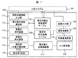
分析システムの構成を、図1に示す。分析システムは、分析部102を統括する上位システム101より依頼情報を測定依頼情報入力部111において受け付ける。測定は、ひとつの検体に対して複数の項目が依頼されるものとする。項目検出感度選択部112により、当該検体の当該項目に対する検出感度は、項目対検出感度選択テーブル121によって検出感度を選択する。この場合、上位システム101にアクセスして、過去のデータにおける測定データの範囲や、他の項目における過去データ、推定される疾患から推測される濃度範囲等を用いてロジックを組むことも可能である。この結果得られた検出感度に従い、感度を決定する高電圧指示装置113により、所定の指示電圧を高電圧発生装置114に出力し、当該指示電圧に従って、高電圧発生装置114は、検出部115である光電子増倍管に1000V程度の高電圧を印加する。高電圧は、例えば600Vから1100Vといった範囲である。ここに、測定依頼情報入力部111と関連づけられて調製,反応された試料が、例えば特開2003−50204号公報に示されるような化学発光方式によって、試料中の測定対象物の濃度に応じて発光し、電流に変換され、電流電圧変換増幅器117に出力される。電流電圧変換増幅器117によって電圧信号に変換された信号は、アナログデジタル(A/D)変換器118により、デジタル信号に変換され、例えば特開2007−85804号公報に示すような積分法によって、特徴量演算部119により特徴量が演算される。この特徴量は、濃度演算部123によって、あらかじめ用意された感度別校正曲線テーブル122によって、濃度に変換され、濃度出力部124より上位システム101に報告する。
The configuration of the analysis system is shown in FIG. The analysis system accepts request information from the
ここで、感度と特徴量の関係について図2を用いて詳細に説明する。横軸にある測定項目における濃度201、縦軸に特徴量として出力信号202を取る。ここで、異なる3つの検出感度における、濃度201と出力信号202の関係、すなわち校正曲線をそれぞれ、高感度モード211,中間感度モード221および低感度モード231とする。例えば光電子増倍管に対する印加電圧として、600Vから1100Vにおいて、高感度モード211では、1000Vを与え、中間感度モード221では850V、低感度モードでは700Vを与える。上限下限に、100Vの裕度があるのは、光電子増倍管による個体差を吸収するために、±100Vの範囲を考慮したためである。ここで例えば、甲状腺刺激ホルモン(TSH)における高感度測定が必要な場合は、高感度モード211の検量線に従う条件を用い、正常範囲を確認するためには中間感度モード221を用いる。さらに、血中濃度が高い疾患に対しては、低感度モード231を用いる。実施例では、直線性を重視し、それぞれの感度モードにおいて、直線の領域のみを使用している。一般に、光電子増倍管においては、光量が小さい側ではノイズの影響により、直線より、やや高めの信号が出る傾向があり、光量が大きい側では、飽和により、直線よりやや低い信号が出、かつ再現性が悪くなる傾向がある。このため、それぞれの感度領域における中央部付近の直線の領域を使うことで、良好な直線性,濃度の変換および補正を容易なものとすることができる。
Here, the relationship between the sensitivity and the feature amount will be described in detail with reference to FIG. The
次に、図1の項目対検出感度選択121における項目と検出感度の考え方について、分析の流れを図3に示す。分析は、検体を採取し、351にて検査項目を測定をシステムに対して登録する。次いで、352にて感度を選択する。感度の選択にあたっては、当該検体の状態、例えば問診において推定された基礎疾患や、病歴および前回測定値といった情報に従って、あらかじめ定められたルールを集めた項目−疾患−感度対応テーブル360に従って、自動的に感度を決定する方法が考えられる。次いで353により測定を実施し、信号量もあるいは信号から演算された特徴量を得る。本明細書では、以下物理的な測定によって得られた情報を特徴量と称する。354にてあらかじめ得られた特徴量とその特徴量を得た時点の感度に対応した検量線を用いて、濃度の演算を行い、355にて、検体に含まれる濃度を報告する。
Next, FIG. 3 shows a flow of analysis regarding the concept of items and detection sensitivity in the item-to-
次に、単一の測定において、測定可能な濃度範囲を調整する方法を示す。先ずこの測定を行うシステムの、検出部分を図Fに示す。401に示す主制御装置によって、検出部が制御される。反応容器431は、化学発光を行うための容器であって、当該容器中に磁性粒子に結合された、発光体が収められている。かかる化学発光方式については、特許参考文献に示されている。発光体に対し、ポンプA411が試薬タンクTA412をノズル413により添加し、しかるのち、ポンプB421がタンクTB422からノズル423より添加することにより発光を行う。これらの液体の添加と化学反応により発光部432が発光する。これを光電子増倍管441により検出する。光電子増倍管に対する入射光を、フィルタ440によって選択しても良い。ここに、複数のフィルタが交換可能とすることもできる。光電子増倍管441は、主制御装置401から与えられたデジタルな感度指示に従い、変換器442にて高電圧発生装置443のアナログ入力電圧に変換され、光電子増倍管441の感度を調整する。光電子増倍管より得られた微弱な電流信号は、対数増幅器444において電圧信号に変換され、さらにアナログデジタル変換器445にて、あらかじめ設定された時間単位の信号量として主制御装置401に送られる。
Next, a method for adjusting a measurable concentration range in a single measurement will be described. First, FIG. F shows a detection portion of the system for performing this measurement. The detection unit is controlled by the
次に時系列のデータ処理について、図5に説明する。時刻軸518に対し、感度を示す光電子増倍管に対する印加電圧511を時系列に示す512同時に得られる信号521を時系列に示す。ここでは、検出部が、バックグラウンド測定を開始するタイミング(t0)530から、特徴量取得のためのデータ取得を完了するタイミング(t7)537までを示す。まず、バックグランド測定は、時刻(t0)530から時刻(t1)531までの区間で取得され、平均値541を得る。この間、印加電圧512は高感度側515となっている。次いで、時刻(t1)531において、光電子増倍管の印加電圧は、低感度側515となる。安定するまでの時刻(t2)532をまって、第二のバックグラウンド542を得る。次いで、時刻(t3)533において、前記ノズル423からの発光のための試薬の注入により、発光が開始される。発光が平坦になる時刻(t4)534は、あらかじめ裕度を含めて求められており、時刻(t4)534から時刻(t5)535までの区間において、同一の印加電圧で得られたバックグラウンド542を除いた、実効的な信号の時間に対する積分値543が特徴量として報告される。さらに時刻(t5)535において、先に述べた高感度側514と同一のレベルの印加電圧とし、バックグラウンド541を用いて、実効的な信号の時間に対する積分値544が特徴量として報告される。このうち、それぞれの感度に対する検量線において、直線部分により近い特徴量を利用し、濃度を演算する。これまでは、検出感度の調整をもっぱら光電子増倍管441における印加高電圧によって説明してきた。しかし、フィルタ450による波長の選択的取得や、低感度側に赤色フィルタ、高感度側に青色フィルタといったように、測定する対象を時系列的に切り替えて、順次測定を行って言っても良い。また、光電子増倍管441の感度とフィルタ450による特性を組み合わせて設定し、フィルタ交換装置451により自動的にフィルタを交換して組み合わせることも可能である。
Next, time-series data processing will be described with reference to FIG. With respect to the
次に、発光プロセスがスパイク状になるケースについて図6を用いて説明する。図の主な構成は、図5と同じである。ここでは信号におけるスパイク691が発生することがもっとも重要である。スパイクがもたらす主要な問題は、短時間のスパイク状の発光691が信号飽和レベル671に到達することにより、スパイク後の信号が乱れることである。これが再現性不良の原因となる。そこで、スパイク形状を示す発光をするシステムにおいて、発光開始直後のスパイク部分については、検出感度を低い印加電圧(615)にて測定し、最大発光量においても、信号飽和レベル671まで到達させない。このときのスパイク頂点のスパイクレベル692を取得し、かかるスパイクからあらかじめ与えられた式に従って、平坦レベルの信号量を推定し、測定感度655のレベルを決定する。この感度で得られた信号による特徴量644を用いて、該当する検量線により濃度を算出する。
Next, a case where the light emission process is spiked will be described with reference to FIG. The main configuration of the figure is the same as that of FIG. Here, it is most important that a
101 上位システム
102 分析部
111 測定依頼情報入力部
112 項目検出感度選択部
113 高電圧指示装置
114 高電圧発生装置
115 検出部
116 発光部
117 電流電圧変換増幅器
118 アナログデジタル変換器
119 特徴量演算部
DESCRIPTION OF
Claims (1)
前記光電子増倍管の感度を調整する感度調整手段と、
当該感度調整手段の感度調整値を予め複数記憶する記憶手段と、
を備えた自動分析装置であって、
測定対象の濃度範囲に対応して前記複数の感度調整値が前記記憶手段に記憶されており、
測定対象に応じて、前記記憶手段に記憶された複数の感度調整値を切り替える切り替え手段を備え、
前記感度調整手段の感度を、発光の最大値が前記光電子増倍管の飽和値より低いレベルに設定し、
当該感度での発光の最大値に基づいて前記感度調整手段の感度を決定し、
当該感度で測定された特徴量に基づいて、測定対象の濃度を決定することを特徴とする自動分析装置。 A detector using a photomultiplier;
A sensitivity adjusting means for adjusting the sensitivity of the photomultiplier;
Storage means for storing in advance a plurality of sensitivity adjustment values of the sensitivity adjustment means;
An automatic analyzer equipped with
The plurality of sensitivity adjustment values corresponding to the concentration range of the measurement target are stored in the storage unit,
According to the measurement object, comprising switching means for switching a plurality of sensitivity adjustment values stored in the storage means,
The sensitivity of the sensitivity adjusting means is set to a level where the maximum value of light emission is lower than the saturation value of the photomultiplier tube,
Determine the sensitivity of the sensitivity adjustment means based on the maximum value of light emission at the sensitivity,
Based on the measured characteristic amount in the sensitivity, automatic analyzer and determining the concentration of the measurement object.
Priority Applications (4)
| Application Number | Priority Date | Filing Date | Title |
|---|---|---|---|
| JP2008066951A JP4887319B2 (en) | 2008-03-17 | 2008-03-17 | Analysis system using automatic analyzer and photomultiplier tube |
| EP09002143.7A EP2103923B1 (en) | 2008-03-17 | 2009-02-16 | Automatic analyzer and analysis system using photomultiplier tube |
| US12/388,300 US20090230291A1 (en) | 2008-03-17 | 2009-02-18 | Automatic analyzer and analysis system using photomultiplier tube |
| CN2009100080024A CN101539582B (en) | 2008-03-17 | 2009-02-19 | Automatic analyzer and analysis system using photomultiplier tube |
Applications Claiming Priority (1)
| Application Number | Priority Date | Filing Date | Title |
|---|---|---|---|
| JP2008066951A JP4887319B2 (en) | 2008-03-17 | 2008-03-17 | Analysis system using automatic analyzer and photomultiplier tube |
Publications (2)
| Publication Number | Publication Date |
|---|---|
| JP2009222536A JP2009222536A (en) | 2009-10-01 |
| JP4887319B2 true JP4887319B2 (en) | 2012-02-29 |
Family
ID=40590025
Family Applications (1)
| Application Number | Title | Priority Date | Filing Date |
|---|---|---|---|
| JP2008066951A Active JP4887319B2 (en) | 2008-03-17 | 2008-03-17 | Analysis system using automatic analyzer and photomultiplier tube |
Country Status (4)
| Country | Link |
|---|---|
| US (1) | US20090230291A1 (en) |
| EP (1) | EP2103923B1 (en) |
| JP (1) | JP4887319B2 (en) |
| CN (1) | CN101539582B (en) |
Families Citing this family (4)
| Publication number | Priority date | Publication date | Assignee | Title |
|---|---|---|---|---|
| JP5124498B2 (en) * | 2009-01-30 | 2013-01-23 | 株式会社日立ハイテクノロジーズ | Automatic analyzer |
| JP6708983B2 (en) * | 2016-01-22 | 2020-06-10 | ソニー株式会社 | Microparticle measuring device, information processing device and information processing method |
| JP6789108B2 (en) * | 2016-12-28 | 2020-11-25 | 富士フイルム株式会社 | Blood analysis method and blood test kit |
| JP7347979B2 (en) * | 2019-07-18 | 2023-09-20 | シスメックス株式会社 | Measuring device, measuring device adjustment method and program |
Family Cites Families (13)
| Publication number | Priority date | Publication date | Assignee | Title |
|---|---|---|---|---|
| JPS59125043A (en) | 1982-12-30 | 1984-07-19 | Shimadzu Corp | Spectro photofluorometer |
| US6190617B1 (en) * | 1992-03-27 | 2001-02-20 | Abbott Laboratories | Sample container segment assembly |
| FI116700B (en) * | 1994-04-28 | 2006-01-31 | Mitsubishi Materials Corp | Continuous flow analysis method and device |
| DE69637001T2 (en) | 1995-06-07 | 2007-12-06 | Bioveris Corp. | Electrochemiluminescent enzyme immunoassay |
| JP2001041891A (en) * | 1999-07-30 | 2001-02-16 | Shimadzu Corp | Method and apparatus for detecting fluorescence |
| JP2001153799A (en) * | 1999-11-29 | 2001-06-08 | Shimadzu Corp | Method and apparatus for quantitative analysis |
| US6664043B2 (en) | 2001-07-03 | 2003-12-16 | Bayer Corporation | Acridinium ester labels having hydrophilic modifiers |
| US6897954B2 (en) * | 2002-12-20 | 2005-05-24 | Becton, Dickinson And Company | Instrument setup system for a fluorescence analyzer |
| JP3960256B2 (en) * | 2003-04-25 | 2007-08-15 | 株式会社島津製作所 | Atomic absorption spectrophotometer |
| CN101052881B (en) * | 2004-10-29 | 2012-06-06 | 爱科来株式会社 | Analyzer, cartridge, and analysis kit |
| JP2007010314A (en) * | 2005-06-28 | 2007-01-18 | Shimadzu Corp | Flame type atomic absorption spectrophotometer |
| JP4521339B2 (en) | 2005-09-21 | 2010-08-11 | 株式会社日立ハイテクノロジーズ | Data processing method with check function in integral data operation method |
| JP2007322395A (en) * | 2006-06-05 | 2007-12-13 | Olympus Corp | Apparatus, method and program for analysis |
-
2008
- 2008-03-17 JP JP2008066951A patent/JP4887319B2/en active Active
-
2009
- 2009-02-16 EP EP09002143.7A patent/EP2103923B1/en active Active
- 2009-02-18 US US12/388,300 patent/US20090230291A1/en not_active Abandoned
- 2009-02-19 CN CN2009100080024A patent/CN101539582B/en active Active
Also Published As
| Publication number | Publication date |
|---|---|
| CN101539582B (en) | 2012-12-26 |
| JP2009222536A (en) | 2009-10-01 |
| US20090230291A1 (en) | 2009-09-17 |
| CN101539582A (en) | 2009-09-23 |
| EP2103923B1 (en) | 2018-08-29 |
| EP2103923A3 (en) | 2011-03-16 |
| EP2103923A2 (en) | 2009-09-23 |
Similar Documents
| Publication | Publication Date | Title |
|---|---|---|
| US7054759B2 (en) | Concentration measuring method | |
| US7760340B2 (en) | Sample analyzer | |
| US8008089B2 (en) | Method and system for checking measurement result | |
| JP2912957B2 (en) | Method and apparatus for measuring enzyme activity | |
| JP5124498B2 (en) | Automatic analyzer | |
| US7727769B2 (en) | Measurement result correction method, urine analysis system, and urine analyzer | |
| TWI600892B (en) | Method and biosensor system for determining analyte concentration in sample | |
| US11860095B2 (en) | Method and sensor for detecting presence or absence of a contaminant | |
| JPH1073535A (en) | Analyzer with means for detecting micro quantity of sample | |
| JP4887319B2 (en) | Analysis system using automatic analyzer and photomultiplier tube | |
| CN107923853A (en) | Automatic analysing apparatus, automatic analysis system and automatic analysis method | |
| JPH0759594A (en) | Measuring humor sample | |
| CN114137197A (en) | Calibration method and device of chemiluminescence immunoassay analyzer | |
| JP5427362B2 (en) | Method and apparatus for measuring hematocrit value or blood component concentration | |
| US20200103428A1 (en) | Calibration curve creation method, analyzer and non-transitory storage medium | |
| JP4838086B2 (en) | Chemiluminescence measuring device | |
| JPH09503856A (en) | Device for measuring the concentration of substances in blood | |
| TWI437222B (en) | Fluorescence detection system, method, and device for measuring biomolecules | |
| JPH07113604B2 (en) | Hemoglobin concentration measuring device | |
| CN117074300A (en) | Sample analyzer and control method thereof |
Legal Events
| Date | Code | Title | Description |
|---|---|---|---|
| A621 | Written request for application examination |
Free format text: JAPANESE INTERMEDIATE CODE: A621 Effective date: 20100226 |
|
| A521 | Request for written amendment filed |
Free format text: JAPANESE INTERMEDIATE CODE: A523 Effective date: 20100226 |
|
| A977 | Report on retrieval |
Free format text: JAPANESE INTERMEDIATE CODE: A971007 Effective date: 20100720 |
|
| A131 | Notification of reasons for refusal |
Free format text: JAPANESE INTERMEDIATE CODE: A131 Effective date: 20100727 |
|
| A521 | Request for written amendment filed |
Free format text: JAPANESE INTERMEDIATE CODE: A523 Effective date: 20100924 |
|
| A131 | Notification of reasons for refusal |
Free format text: JAPANESE INTERMEDIATE CODE: A131 Effective date: 20110201 |
|
| A521 | Request for written amendment filed |
Free format text: JAPANESE INTERMEDIATE CODE: A523 Effective date: 20110523 |
|
| TRDD | Decision of grant or rejection written | ||
| A01 | Written decision to grant a patent or to grant a registration (utility model) |
Free format text: JAPANESE INTERMEDIATE CODE: A01 Effective date: 20111115 |
|
| A01 | Written decision to grant a patent or to grant a registration (utility model) |
Free format text: JAPANESE INTERMEDIATE CODE: A01 |
|
| A61 | First payment of annual fees (during grant procedure) |
Free format text: JAPANESE INTERMEDIATE CODE: A61 Effective date: 20111212 |
|
| FPAY | Renewal fee payment (event date is renewal date of database) |
Free format text: PAYMENT UNTIL: 20141216 Year of fee payment: 3 |
|
| R150 | Certificate of patent or registration of utility model |
Ref document number: 4887319 Country of ref document: JP Free format text: JAPANESE INTERMEDIATE CODE: R150 Free format text: JAPANESE INTERMEDIATE CODE: R150 |
|
| S531 | Written request for registration of change of domicile |
Free format text: JAPANESE INTERMEDIATE CODE: R313531 |
|
| S533 | Written request for registration of change of name |
Free format text: JAPANESE INTERMEDIATE CODE: R313533 |
|
| R350 | Written notification of registration of transfer |
Free format text: JAPANESE INTERMEDIATE CODE: R350 |