JP4879471B2 - Method and apparatus for determining position in response to retroreflective objects - Google Patents
Method and apparatus for determining position in response to retroreflective objects Download PDFInfo
- Publication number
- JP4879471B2 JP4879471B2 JP2004248127A JP2004248127A JP4879471B2 JP 4879471 B2 JP4879471 B2 JP 4879471B2 JP 2004248127 A JP2004248127 A JP 2004248127A JP 2004248127 A JP2004248127 A JP 2004248127A JP 4879471 B2 JP4879471 B2 JP 4879471B2
- Authority
- JP
- Japan
- Prior art keywords
- retroreflected
- beams
- frequency
- angular position
- coordinates
- Prior art date
- Legal status (The legal status is an assumption and is not a legal conclusion. Google has not performed a legal analysis and makes no representation as to the accuracy of the status listed.)
- Expired - Fee Related
Links
Images


Classifications
-
- G—PHYSICS
- G01—MEASURING; TESTING
- G01S—RADIO DIRECTION-FINDING; RADIO NAVIGATION; DETERMINING DISTANCE OR VELOCITY BY USE OF RADIO WAVES; LOCATING OR PRESENCE-DETECTING BY USE OF THE REFLECTION OR RERADIATION OF RADIO WAVES; ANALOGOUS ARRANGEMENTS USING OTHER WAVES
- G01S17/00—Systems using the reflection or reradiation of electromagnetic waves other than radio waves, e.g. lidar systems
- G01S17/02—Systems using the reflection of electromagnetic waves other than radio waves
- G01S17/06—Systems determining position data of a target
- G01S17/46—Indirect determination of position data
- G01S17/48—Active triangulation systems, i.e. using the transmission and reflection of electromagnetic waves other than radio waves
-
- G—PHYSICS
- G06—COMPUTING; CALCULATING OR COUNTING
- G06F—ELECTRIC DIGITAL DATA PROCESSING
- G06F3/00—Input arrangements for transferring data to be processed into a form capable of being handled by the computer; Output arrangements for transferring data from processing unit to output unit, e.g. interface arrangements
- G06F3/01—Input arrangements or combined input and output arrangements for interaction between user and computer
- G06F3/03—Arrangements for converting the position or the displacement of a member into a coded form
- G06F3/033—Pointing devices displaced or positioned by the user, e.g. mice, trackballs, pens or joysticks; Accessories therefor
- G06F3/0354—Pointing devices displaced or positioned by the user, e.g. mice, trackballs, pens or joysticks; Accessories therefor with detection of 2D relative movements between the device, or an operating part thereof, and a plane or surface, e.g. 2D mice, trackballs, pens or pucks
- G06F3/03543—Mice or pucks
-
- G—PHYSICS
- G06—COMPUTING; CALCULATING OR COUNTING
- G06F—ELECTRIC DIGITAL DATA PROCESSING
- G06F3/00—Input arrangements for transferring data to be processed into a form capable of being handled by the computer; Output arrangements for transferring data from processing unit to output unit, e.g. interface arrangements
- G06F3/01—Input arrangements or combined input and output arrangements for interaction between user and computer
- G06F3/03—Arrangements for converting the position or the displacement of a member into a coded form
- G06F3/041—Digitisers, e.g. for touch screens or touch pads, characterised by the transducing means
- G06F3/042—Digitisers, e.g. for touch screens or touch pads, characterised by the transducing means by opto-electronic means
- G06F3/0421—Digitisers, e.g. for touch screens or touch pads, characterised by the transducing means by opto-electronic means by interrupting or reflecting a light beam, e.g. optical touch-screen
- G06F3/0423—Digitisers, e.g. for touch screens or touch pads, characterised by the transducing means by opto-electronic means by interrupting or reflecting a light beam, e.g. optical touch-screen using sweeping light beams, e.g. using rotating or vibrating mirror
Description
本発明は、一般に、物体の位置決定方法および位置決定装置に関するものであり、とりわけ、光学位置決定方法および装置に関するものである。 The present invention relates generally to an object position determination method and position determination apparatus, and more particularly to an optical position determination method and apparatus.
機械式マウスは、カーソルの位置決めをして、さまざまなアプリケーションにおける機能を選択するのに有用なツールとして、コンピュータ・ユーザには周知のところである。これらの機械式マウスは、ボールと、関連センサを利用して、相対運動を検出する。しかし、機械式マウスは、相対座標トラッキングを利用しており、一般に可動部を有し、2次元位置入力に制限され、分解能が低く、特定の表面においてしか有効に機能しない。
光学式マウスは、光を利用して、相対運動を検出する。一般に、光学式マウスは、マウス・パッドまたはテーブル表面のようなある表面を照射するための、発光ダイオード(LED)のような光源を備えている。光が表面に当たると、光の一部は反射される。光学式マウスは、反射光を検出するための搭載検出器を備えている。電子計算装置が、反射光に基づいて、光学式マウスの相対運動を測定する。
A mechanical mouse is well known to computer users as a useful tool for positioning a cursor and selecting functions in various applications. These mechanical mice use balls and associated sensors to detect relative movement. However, mechanical mice use relative coordinate tracking, generally have moving parts, are limited to two-dimensional position input, have low resolution, and function effectively only on specific surfaces.
An optical mouse uses light to detect relative movement. In general, an optical mouse includes a light source, such as a light emitting diode (LED), for illuminating a surface, such as a mouse pad or table surface. When light hits the surface, part of the light is reflected. The optical mouse includes an on-board detector for detecting reflected light. An electronic computing device measures the relative movement of the optical mouse based on the reflected light.
光学式マウスは、機械式マウスの制限のいくつかを克服するが、やはり、2次元位置入力に制限され、相対座標トラッキングを利用し、ミラーのような特定の表面には有効に機能しない。さらに、LED及び電子計算装置は、光学式マウスにおける電源の利用を必要とする。
本発明は、上記課題を解決し、走査空間内における再帰反射物体の角位置に関連した周波数を有する分散ビームの一部を再帰反射することによって、再帰反射物体の第2の角位置を求め、2つの角位置を利用して再帰反射物体の座標を求めることができる位置決定方法および装置を提供することを目的とする。
Optical mice overcome some of the limitations of mechanical mice, but are also limited to two-dimensional position input, utilize relative coordinate tracking, and do not function effectively on certain surfaces such as mirrors. Furthermore, LEDs and electronic computing devices require the use of a power source in an optical mouse.
The present invention solves the above-mentioned problem and obtains the second angular position of the retroreflective object by retroreflecting a part of the dispersed beam having a frequency related to the angular position of the retroreflective object in the scanning space, It is an object of the present invention to provide a position determination method and apparatus capable of obtaining the coordinates of a retroreflective object using two angular positions.
ある位置決定技法では、周波数依存回折(分散とも称する)を利用して、走査空間内における再帰反射物体の角位置が決定される。この技法には、周波数に基づいて、電磁(EM)ビームを走査空間内に分散することが必要になる。再帰反射物体は、走査空間内に配置されると、走査空間内における再帰反射物体の角位置に関連した周波数を有する分散ビームの一部を再帰反射する。再帰反射ビ−ムの周波数を利用して、走査空間内における再帰反射物体の角位置が決定される。第2のビームが走査空間内に分散され、第2のビームの一部が、説明したばかりのように再帰反射されると、再帰反射物体の第2の角位置を求めることが可能になる。再帰反射物体の座標は、2つの角位置を利用して、三角測量によって求められる。これらは、相対座標ではなく、絶対座標である。再帰反射物体の空間(3次元)座標は、3つ以上の角位置を利用して、三角測量によって求めることが可能である。 One position determination technique utilizes frequency dependent diffraction (also referred to as dispersion) to determine the angular position of a retroreflective object in scan space. This technique requires that an electromagnetic (EM) beam be distributed in the scan space based on frequency. When the retroreflective object is placed in the scan space, it retroreflects a portion of the dispersed beam having a frequency related to the angular position of the retroreflective object in the scan space. The angular position of the retroreflective object in the scanning space is determined using the frequency of the retroreflective beam. When the second beam is dispersed in the scan space and a portion of the second beam is retroreflected as just described, it is possible to determine the second angular position of the retroreflective object. The coordinates of the retroreflective object are obtained by triangulation using two angular positions. These are absolute coordinates, not relative coordinates. The space (three-dimensional) coordinates of the retroreflective object can be obtained by triangulation using three or more angular positions.
例証を目的とした図面に示すように、本発明は、位置決定に関するものである。実施態様の1つでは、本発明は、周波数依存回折に基づいて、走査空間内における再帰反射物体の角位置を決定する。 As shown in the drawings for purposes of illustration, the present invention relates to position determination. In one embodiment, the present invention determines the angular position of the retroreflective object in the scan space based on frequency dependent diffraction.
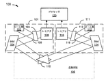
図1は、本発明による、走査空間130内に配置された再帰反射物体110に応答する位置決定システム100のブロック図である。図1の目的は、走査空間130のそれぞれの半径方向部分に関連した分散ビームの周波数値を利用して、再帰反射物体110の座標を計算する方法を例示することにある。システム100は、この周波数値を利用して、再帰反射物体110の角位置を計算し、角位置を利用して、再帰反射物体110の座標を三角測量することが可能である。(分散ビームの周波数値と走査空間130内における再帰反射物体110の半径方向位置との関係については、図2A及び図2Bに関連して後述する。この関係について解説するまで、ただ単に、こうした関係が存在するものと仮定しておく。)
FIG. 1 is a block diagram of a
システム100には、第1の角位置決定サブシステム101、第2の角位置決定サブシステム111、及び、プロセッサ120が含まれている。プロセッサは、コンピュータ技術において周知のところである。従って、本明細書では、プロセッサ120に関する詳細な説明は控えることにする。ただし、留意しておくべきは、プロセッサは、一般に、機能を実行するための命令を含む記憶媒体に結合されているという点である。記憶媒体は、命令がハードウェアで実施される場合、必要になることもあれば、不要になることもあり得る。従って、本明細書において用いられる限りにおいて、プロセッサ120は、関連する記憶媒体のない(オプションのレジスタ以外に)ハードウェア装置とすることが可能である。さらに、本明細書において用いられる限りにおいて、プロセッサ120は、実際には、マルチプロセッサまたは複数プロセッサとすることが可能である。
The
プロセッサ120は、入力として、2つのサブシステム101及び111の出力を受信する。実施態様の1つでは、2つのサブシステム101及び111の出力は周波数値である。プロセッサ120は、周波数値に対応する再帰反射物体(retro-reflective object)110の角位置を決定する。プロセッサ120は、次に、角位置を用いて、再帰反射物体110の座標を三角測量し、それに基づいて、再帰反射物体110の位置を決定する。ある代替実施態様では、サブシステム101及び111に、周波数から角位置を求め、プロセッサ120に対して角位置を出力する独立したプロセッサ(不図示)が設けられており、プロセッサ120は、この角位置を用いて、再帰反射物体110の座標を三角測量し、それに基づいて、再帰反射物体110の位置を決定する。
The
実施態様の1つでは、プロセッサ120は、コンピュータ・モニタ(不図示)のような出力装置に結合されている。プロセッサによって、走査空間130内における再帰反射物体110の座標が計算されるので、出力装置において、走査空間130内における再帰反射物体110の移動を表示することが可能である。ある代替実施態様では、再帰反射物体110の移動が記憶媒体に記憶される。もう1つの代替実施態様では、再帰反射物体110がコンピュータ入力装置として利用される。好都合なことには、再帰反射物体110は、再帰反射マウスまたはタッチ・スクリーン入力装置を含む、あるいは、書き込み端部に再帰反射表面を備えたペン、または、人の指または任意の物体に取り付けられた再帰反射テープさえ含む、ほぼ任意の再帰反射物体とすることが可能である。再帰反射物体110は、束縛をなくし、電力を消費せず、可動部を含まず、例えば、再帰反射テープのように、低コストにすることが可能である。
In one embodiment, the
サブシステム101には、電磁(EM)ビーム源102、部分反射表面103、ビーム分散装置(BDD)104、及び、レセプタ106が含まれている。EMビーム源102は、狭帯域の同調可能または掃引ビーム源、あるいは、発光ダイオード(LED)、光増幅器、白熱灯、または、EMビームを生じる他の何らかの装置を利用する、広帯域の光源とすることが可能である。広帯域及び狭帯域の同調可能ビーム源を利用する典型的な実施態様については、それぞれ、図3A及び図3Bに関連して後述する。EMビーム源は、光ファイバ、または、EMビームを供給するための他の何らかの装置とすることも可能である。部分反射表面103は、部分反射ミラー、偏光ビーム・スプリッタ、または、他の何らかの部分反射表面とすることが可能である。偏光ビーム・スプリッタを利用する典型的な実施態様については、図3A及び図3Bに関連して後述する。BDD104は、回折格子、プリズム、ホログラフィック素子、または、他の何らかのビーム分散装置とすることが可能である。回折格子を利用する典型的な実施態様については、図3A及び図3Bに関連して後述する。レセプタ106は、波長計、光検出器、または、他の何らかの周波数測定またはEM放射線検出装置とすることが可能である。波長計及び光検出器を利用する典型的な実施態様については、それぞれ、図3A及び図3Bに関連して後述する。
再帰反射物体110に入射するEMビームは、それが来た方向に反射される。再帰反射は、光物理学において周知のところである。再帰反射物体は、EM放射線を入射方向と平行な方向に反射する。再帰反射物体は、角度つき金属メッキミラーを利用して、または、テープまたはスプレーによる幾何学形状をなす低コスト・アレイによって製造することが可能である。
The EM beam incident on the
動作時、EMビーム源102は、部分反射表面103に入射するEMビーム108を発生する。EMビーム108の一部は、BDD104に向かって反射される。EMビーム108が広帯域ビーム源からのものであれば、BDD104は、複数周波数にビームを分散する。一方、EMビーム108が同調可能(または掃引)ビーム源からのものであれば、同調可能ビーム源は、時間依存可変周波数を備えたEMビームを発生する。換言すれば、ある時間期間にわたって、同調可能ビーム源は、順番に、ある範囲の周波数を飛び越すのが望ましい。BDD104は、EMビームの周波数に関連した回折角度でEMビームを分散させる。BDD104からのビームの最初の反射が済むと、本明細書では、そのビームは、「分散ビーム」と呼ばれる。周波数と回折角の関係は、位置決定にとってクリティカルであるため、特定の分散装置の周波数依存特性を得ることが必要である。この情報は、例えば、回折図、回折測定、または、他の技法を通じて得ることが可能である。
In operation, the
EMビームが狭帯域ビーム源からのものであるか、広帯域ビーム源からのものであるかにかかわらず、BDD104は、分散ビームを走査空間130に送り込む。走査空間130内に再帰反射物体110が存在する場合、分散ビームが、再帰反射物体110の配置されている走査空間130の半径方向部分に向けて送られるものと仮定すると、再帰反射物体110は、分散ビームの少なくとも一部をBDD104に向かって再帰反射するはずである。BDD104は、次に、再帰反射ビームを部分反射表面103の方に向け直す。再帰反射ビームの一部は、部分反射表面103を通過し、レセプタ106によって検出される。プロセッサ120は、周波数値(例えば、波長計からの)とすることもできるし、あるいは、ただ単に、再帰反射ビームに関連したEM信号を検出した旨の表示(例えば、光検出器からの)とすることも可能な、レセプタ106の出力を受信する。レセプタ106が、波長計の場合、再帰反射ビームの周波数(または波長)を測定する。レセプタ106が光検出器の場合、一般に、ある時点tにおけるEMビーム108の周波数は分るはずであり、従って、レセプタ106が、時点tにおいて再帰反射ビームを検出すると、再帰反射ビームの周波数を推定することが可能である
Regardless of whether the EM beam is from a narrow beam source or a broadband beam source, the
サブシステム111には、EMビーム源112、部分反射表面113、BDD114、レセプタ116、及び、EMビーム118が含まれている。サブシステム111は、サブシステム101と同様である。従って、サブシステム101についてのみ詳述する。
前述のように、サブシステム101及び111は、それぞれ、再帰反射物体110の角位置を求める(あるいは、それに基づいて、プロセッサ120による角位置の決定が可能になる周波数値を出力する)。追加角位置決定サブシステム(不図示)が、システム100に組み込まれている場合、3次元位置決定システム(不図示)が可能になる。このシステムは、再帰反射物体110の3つの角位置を求めて、それに基づいて、再帰反射物体110の空間座標を三角測量する。利用される角位置決定サブシステムの数に関係なく、プロセッサ120は、角位置を用いて、再帰反射物体110の座標(3次元実施態様の場合、空間座標)を三角測量することが可能である。角位置を利用した三角測量は、数学技術において周知のところであり、本発明での詳述は控えることにする。
As described above, each of the
図2A及び図2Bには、本発明による物体座標と分散ビームとの関係が例示されている。すなわち、図2Aには、走査空間230の半径方向部分とそれぞれの分散ビームの周波数(または波長)との関係が例示され、図2Bには、再帰反射物体210の座標とそれぞれの分散ビームの周波数との関係が例示されている。
2A and 2B illustrate the relationship between the object coordinates and the dispersed beam according to the present invention. That is, FIG. 2A illustrates the relationship between the radial portion of the
周波数依存分散(または回折)は、周知の現象である。この現象は、光を周波数依存レインボー・パターンに回折するプリズム(周知のビーム分散装置)を利用して、例証される場合もある。図2Aには、周波数依存パターンを走査空間230に広げることが可能な方法が示されている。
Frequency dependent dispersion (or diffraction) is a well-known phenomenon. This phenomenon may be illustrated using a prism (known beam disperser) that diffracts light into a frequency dependent rainbow pattern. FIG. 2A shows how a frequency dependent pattern can be spread over the
狭帯域同調可能(または掃引)ビーム源は、周波数が経時変化するEMビームを送り出すことが可能である。EMビームが、時間経過につれて走査空間230に分散する場合、走査空間230の最初の半径方向部分を時点0と関連づけ、走査空間230の最後の半径方向部分を時点Nと関連づけることが可能である。従って、時点0における分散ビームは、周波数がf0になるはずである。時間インクリメント(increment)1つ分が経過すると、分散ビームの周波数はf1になるはずである。時点tにおいて、分散ビームの周波数はftになるはずである。時点Nにおいて、分散ビームの周波数はfNになるはずである。時点Nの後、掃引ビーム源は、周波数f0から再始動する(または、f0とfNの間のある任意の周波数から再始動する)。こうして、分散ビームは、走査空間230の半径方向部分と周波数が関連づけられるようなやり方で、走査空間230の半径方向部分をカバーする。掃引ビーム源の代わりに、広帯域ビーム源が用いられる場合、EMビームは走査空間230内に同時に分散される。再帰反射物体の角変位は、図2Bに関連して解説のように、特定の周波数の分散角の関数として求められる。
A narrowband tunable (or swept) beam source can deliver an EM beam whose frequency changes over time. If the EM beam is dispersed in
図2Bには、BDD204(図1のBDD104と同様の)及びBDD214(図1のBDD114と同様の)が含まれている。例証のため、BDD204によって分散されるEMビームは、狭帯域同調可能(または掃引)ビーム源から生じるものと仮定する。BDD204は、EMビームを周波数に基づいて分散させる。すなわち、分散ビームの回折角は、分散ビームの周波数(または波長)の関数である。大まかな例として、もう一度プリズムの例を用いると、EMビーム源は、赤から紫まで掃引した後、再び、赤からやり直す(EMビームが可視光の周波数範囲内であると仮定すると)。こうして、任意の特定の時点tにおいて、BDD204は、EMビームを分散して、周波数がftの分散ビームにする。分散ビームは、周波数ftに対応する走査領域の半径方向部分に向けて送られる。再帰反射物体210は、周波数ftに対応する走査領域の部分内にあれば、周波数ftの分散ビームを再帰反射して、BDD204に、最終的には、図1に関連して既述のレセプタ(不図示)に送り返すことになるはずである。
2B includes BDD 204 (similar to
BDD214は、BDD204と全く同様に機能する。図2Bにおいて、BDD214によって分散された分散ビームの周波数は、f0'〜fN'で表わされている。前述のように、時点tにおいて、周波数がftの分散ビームは、再帰反射物体210から再帰反射されて、BDD204に向かって戻される。同様に時点t’において、周波数がft'の分散ビームは、再帰反射物体210から反射されて、BDD214に向かって戻される。これらの周波数ft及びft'は、それぞれ、走査空間230の半径方向位置と関連しているので、再帰反射物体210のそれぞれの角位置は、それに基づいて計算することが可能である(周波数が、測定されるか、または、別様に分るものと仮定する)。次に、前述のように、再帰反射物体210の座標を三角測量することが可能である。
The
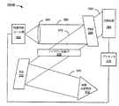
図3A及び図3Bは、本発明による角位置決定システムの典型的なブロック図である。図3Aは、広帯域ビーム源を用いて、再帰反射物体312の位置を決定するシステム300Aの例を示すことを意図したものである。図3Aには、部分反射表面103(図1)の実施態様の1つとして、ファラデー回転子(Faraday rotator)を備えた偏光ビーム・スプリッタ(PBS)306の利用も例示されている。ビーム源が、図3Aにおけるような広帯域ビーム源302であるか、あるいは、図3Bにおけるような狭帯域同調可能ビーム源352であるかにかかわらず、PBS306及びファラデー回転子308の組み合わせを利用することが可能であるという点に留意されたい。システム300Aは、前述のサブシステム101(図1)と同様である。システム300Aには、広帯域ビーム源302、レンズ304、PBS306、ファラデー回転子(Faraday rotator)308、回折格子(DG)310、波長計314、及び、プロセッサ316が含まれている。
3A and 3B are exemplary block diagrams of an angular position determination system according to the present invention. FIG. 3A is intended to illustrate an example of a
動作時、EMビームが、広帯域ビーム源302によってレンズ304に送られ、レンズ304によって集束させられて、PBS306に向かう光路320に送り込まれる。PBS306は、第1の偏光状態のEM放射線を反射するが、第1の偏光状態に対して直交する第2の偏光状態のEM放射線は通過させる。広帯域ビーム源302は、この例の目的が、第1の偏光状態のEMビームを送り出すことにあるものと仮定している。代替実施態様では、第1の偏光状態のEMビームを送り出す広帯域ビーム源302の代わりに、広帯域ビーム源302とPBS306の間に配置された偏光子(不図示)を利用して、EMビームの偏光状態を変えることが可能である。もう1つの代替実施態様では、広帯域ビーム源302によって、非偏光EMビームを生じさせることが可能であり、この場合、EMビームの一部は、PBS306を通過し、EMビームの一部は、反射される。いずれにせよ、PBS306は、ファラデー回転子308に向かう光路330に沿って、EMビームの少なくとも一部を反射する。ファラデー回転子308は、EMビームがDG310に向かって通過する際に、EMビームの偏光状態を45°回転させる。この回転の意味は、光路330に沿って戻るビームの偏光状態がもう一度45°回転して、全部で、90°回転することになり、第1の偏光状態に対して直交する(すなわち、PBS306によって反射されたEM放射線の偏光状態に対して直交する)ということである。従って、ビームは、その帰路においてPBS306を通過することになる。
In operation, the EM beam is sent to the
DG310は、周波数依存角でEMビームを分散するように構成されている。典型的な分散ビームは、光路340に沿って送られる。再帰反射物体312は、光路340内に配置されている。DG310は、一般に、広帯域ビーム源からのEMビームを走査空間に同時に分散するが、図が乱雑になるのを避けるため、再帰反射物体312に入射する分散ビームの一部だけしか例示されていない。再帰反射物体312は、分散ビームの一部を再帰反射し、光路340に沿ってDG310に送り返す。DG310は、次に、EMビームが最初に来た方向に(換言すれば、光路330に)再帰反射ビームの向きを直し、ファラデー・リフレクタ(reflector)308を通って、PBS306に戻るようにする。
The
前述のように、EMビームの偏光状態が第1の偏光状態であったので、PBS306は、最初にEMビームを反射した。ビームは、その光路においてファラデー・リフレクタ308を通過して、再帰反射物体312に向かい、再帰反射ビームは、再帰反射物体312からの帰路においてファラデー・リフレクタ308を通過したので、再帰反射ビームは、第2の偏光状態にある(すなわち、第1の偏光状態に対して直交している)。従って、前述のように、PBS306は、次に、再帰反射ビームが光路350においてPBS306を通過して、波長計314に向かうようにする。波長計314は、再帰反射ビームの周波数を測定する。プロセッサ316は、波長計314から測定周波数を受信し、その測定周波数を利用して、再帰反射物体312の角位置を求める。
As described above, since the polarization state of the EM beam was the first polarization state, the
図3Bは、狭帯域同調可能ビーム源を利用して、再帰反射物体312の位置を決定するシステム300Bの一例を示すことを意図したものである。システム300Bは、前述のサブシステム300A(図3A)と同様であるが、広帯域ビーム源302の代わりに同調可能ビーム源352を利用し、波長計314の代わりに光検出器364を利用する。
FIG. 3B is intended to illustrate an
動作時、時間依存可変周波数のEMビームが、同調可能ビーム源352によって、光路360に沿ってPBS306に送られ、PBS306によって、向きを直されて、光路370に沿って進み、ファラデー回転子308を通って、DG310に送られる。DG310は、EMビームの周波数によって決まる角度でEMビームを分散させる。この場合のEMビームは、可変周波数であるため、EMビームは、可変周波数に関連した角度で分散ビームとして分散される。再帰反射物体312が分散ビームに関連した角位置にあるものと仮定すると、DG310は、光路380に沿って、EMビームを再帰反射物体312に対して分散させる。再帰反射物体312は、分散ビームを再帰反射し、光路380に沿ってDG310に送り返す。次に、再帰反射ビームは、DG310によって向きが直されて、光路370に沿って進み、ファラデー回転子308を通って、PBS306に送り返されるが、さらに、再帰反射ビームは、PBS306によって、光検出器364に送られて、検出されることになる。
In operation, a time dependent variable frequency EM beam is sent by the
広帯域ビーム源302(図3A)の場合とは異なり、時点tにおいて、同調可能ビーム源352は、既知の周波数ftを備えることが可能であるが、ここで、この周波数は、既知の技法によって得られる。既知の技法には、例えば、レーザに組み込まれたMEMアクチュエータに印加される電圧とレーザの周波数出力との間に一定の関係がある場合に、印加電圧によってその周波数が制御される同調可能レーザ源を利用することが含まれる。あるいはまた、レーザに波長計を組み込み、1つ以上の光学エタロンによって、レーザ出力の一部をサンプリングして、その出力が光周波数の決定に用いられる1つ以上の検出器に、信号を供給することも可能である。これら既知の技法の1つを用いることによって、時点tにおける同調可能ビーム源352の周波数ftが分る。従って、光検出器364は、時点tにおける再帰反射ビームを検出すると、再帰反射ビームが周波数ftのEMビームに関連しているか推測することが可能になる。光検出器からの出力が、再帰反射ビームが時点tにおいて検出されたことを示している場合、プロセッサ376は、既知周波数ftを利用して、再帰反射物体312の角位置を求める。留意すべきは、同調可能ビーム源352からのEMビームが光検出器364に到達するのに要する時間量が比較的少なく、従って、例示の目的からして、その遅延は無視されるという点である。
Unlike the broadband source 302 (FIG. 3A), at time t,
さらに留意すべきは、同調可能ビーム源を備えた光検出器の代わりに、波長計を利用することが可能であるという点である。波長計は、周知のところであって、光学エタロンから、あるいは、光回折格子、または、波長によって決まる光透過のような測定可能特性を示す任意の装置といった分散装置を用いることによって、製作することが可能である。波長計を含む代替実施態様の場合、システムは、時点tにおける同調可能ビーム源の周波数に関して、同調可能ビーム源からフィードバックを受けることはできない。従って、波長計によって、検出された各再帰反射ビームの周波数を測定する。 It should be further noted that a wavelength meter can be used instead of a photodetector with a tunable beam source. Wavemeters are well known and can be fabricated from an optical etalon or by using a dispersion device such as an optical diffraction grating or any device that exhibits measurable properties such as light transmission determined by wavelength. Is possible. In an alternative embodiment including a wavemeter, the system cannot receive feedback from the tunable beam source regarding the frequency of the tunable beam source at time t. Therefore, the frequency of each detected retroreflected beam is measured by the wavelength meter.
2つの角位置決定サブシステムを一緒に動作させることによって、再帰反射物体に関して、2つの角位置を求め、図1に関連して前述のように、それらの角位置から再帰反射物体の座標を求めることが可能になる。留意すべきは、2次元実施態様の場合、こうしたシステムは、2次元走査空間に直交する方向に、再帰反射物体の限定トラッキング範囲を備えることができるという点である。この限定トラッキング範囲は、図4に関連して解説のように、楕円EMビームを用いて改善することが可能である。 By operating the two angular position determination subsystems together, the two angular positions are determined for the retroreflective object and the coordinates of the retroreflective object are determined from those angular positions as described above in connection with FIG. It becomes possible. It should be noted that in the case of a two-dimensional embodiment, such a system can have a limited tracking range of retroreflective objects in a direction orthogonal to the two-dimensional scanning space. This limited tracking range can be improved using an elliptical EM beam, as described in connection with FIG.
図4には、本発明による2次元走査空間に直交する方向に沿ったトラッキング範囲が例示されている。走査空間には、第1の走査空間402と第2の走査空間404が含まれている。座標軸410は、走査空間に直交している。第1のポイント420は、第1の走査空間402内に位置しており、第2のポイント430は、第2の走査空間404内に位置している。
FIG. 4 illustrates a tracking range along a direction orthogonal to the two-dimensional scanning space according to the present invention. The scanning space includes a
第1の走査空間402に関連したシステムは、ポイント420における再帰反射体の位置を検出することができるが、ポイント430における再帰反射体の位置を検出することはできなくなる。この問題は、例えば、楕円EMビームのような拡大ビームを利用して、第3の(直交)次元に走査空間を拡大することによって、ある程度改善することが可能である。拡大走査空間が、第2の走査空間404によって例示されている。例えば、楕円EMビームを利用することによって、システムは、ポイント430に配置された再帰反射体を検出することが可能になる。走査空間402から上方または下方に移動した再帰反射物体に関して、システムの許容差が改善されるが、直交方向における再帰反射物体の位置が測定されないので、システムは、やはり、2次元と称される。
The system associated with the
図5は、本発明によるEM位置決定コンピュータ・システム500のブロック図である。システム500には、プロセッサ502、コンピュータ可読媒体504、入力装置506、及び、モニタ508が含まれている。コンポーネントのそれぞれが、バス510に結合されている。コンピュータ可読媒体には、プログラム命令512及び514が含まれている。プロセッサ502は、プログラム命令を実行する。プログラム命令512では、入力装置506によって、EM信号の検出を知らせる入力が与えられると、周波数値に基づいて角位置の計算を行う。プログラム命令514では、2つ以上の角位置を利用して座標の三角測量を行う。座標は、例えば、モニタ508に矢印、カーソル、または、他の何らかの表示記号として表示するため、バス510に出力される。
FIG. 5 is a block diagram of an EM
システム500は、システム100(図1)と共に利用することが可能である。実際、ある実施態様では、プロセッサ502に、プロセッサ120(図1)が含まれ、入力装置506に、サブシステム101及び111(図1)が含まれている。
図6Aには、2次元走査空間において再帰反射物体の位置を決定するための方法のフローチャート600Aが例示されている。フローチャート600Aには、2つの開始点がある。フローチャート600Aは、第1の開始点から開始すると、ステップ602において、第1のEMビームを発生し、ステップ604において、EMビームを周波数に基づいて分散し、ステップ606において、再帰反射物体から分散ビームを再帰反射させ、ステップ608において、再帰反射ビームの周波数から再帰反射物体の第1の角位置を求める。第1のEMビームは、広帯域ビーム源からのものとすることが可能であるが、その場合、時点tにおいて、EMビームは、ある波長範囲にわたって同時に分散される。EMビームが掃引ビーム源からのものであれば、EMビームは、時間の関数としてのある波長範囲にわたって分散される。
FIG. 6A illustrates a
フローチャート600Aは、第2の開始点から開始すると、ステップ612において、第2のEMビームを発生し、ステップ614において、EMビームを分散ビームに分散し、ステップ616において、再帰反射物体から分散ビームを再帰反射させ、ステップ618において、再帰反射ビームの周波数から再帰反射物体の第2の角位置を求める。第1のEMビームと同様、第2のEMビームは、広帯域ビーム源または掃引ビーム源からのものとすることが可能である。第1の角位置及び第2の角位置の両方が求められると(ステップ608及び618において)、ステップ620において、第1の角位置と第2の角位置を利用して、再帰反射物体の座標を三角測量することが可能になる。これで、フローチャート600Aが終了する。
図6Bには、2次元または3次元走査空間における再帰反射物体の位置を決定するための方法のフローチャート600Bが例示されている。ステップ622において、1つ以上のEMビームを発生する。ステップ624において、EMビームはそれぞれの分散ビームに分散される。ステップ626において、それぞれの分散ビームは、再帰反射物体から再帰反射される。ステップ628において、それぞれの再帰反射ビームに関連した周波数を用いて、再帰反射物体のそれぞれの角位置が求められる。ステップ630において、それぞれの角位置の2つ以上を利用して、再帰反射物体の座標が三角測量される。それぞれの角位置の3つ以上を利用すると、再帰反射物体の空間(すなわち、3次元)座標を三角測量することが可能になる。
FIG. 6B illustrates a
EMビームに関連して用いられる場合、分散という用語は、本明細書では、大まかに言って、EMビームの反射、回折、または、別様の方向づけを含むものと定義される。EMビームの分散には、EMビームを周波数依存帯域に分割すること、あるいは、EMビームがある(中心)周波数を有する場合、その周波数に基づいて、EMビームの向きを直すことを含むことが可能である。 When used in connection with an EM beam, the term dispersion is broadly defined herein to include reflection, diffraction, or other orientation of the EM beam. Dispersion of the EM beam can include dividing the EM beam into frequency dependent bands, or, if the EM beam has a certain (center) frequency, reorienting the EM beam based on that frequency. It is.
本明細書において用いられる限りにおいて、広帯域ビーム源という用語は、大まかに、スペクトル的に広帯域のEMビームを生じる広帯域ビーム源を含むものと定義される。 As used herein, the term broadband beam source is broadly defined to include a broadband beam source that produces a spectrally broadband EM beam.
本発明の特定の実施態様について解説し、例示してきたが、本発明は、本明細書に解説及び例示した部分の特定の形態または構成に制限すべきではない。本発明は、特許請求の範囲による制限しか受けない。
記載を通して、同じ参照番号は同じ要素を示すように用いられる。
Although specific embodiments of the present invention have been described and illustrated, the present invention should not be limited to the specific forms or configurations of parts described and illustrated herein. The present invention is limited only by the claims.
Throughout the description, the same reference numerals are used to indicate the same elements.
108 電磁ビーム
110 再帰反射物体
108
Claims (20)
物体の位置を決定するために光源から光ビームとして1つ以上の電磁(EM)ビームを生じるステップと、
前記1つ以上のEMビームを、ビーム分散装置によって、それぞれ、前記EMビームの周波数に関連した回折角度で、走査空間に分散するステップと、
前記走査空間内に配置された物体から、前記それぞれの分散ビームの少なくとも一部を前記ビーム分散装置に向かって再帰反射させるステップと、
前記再帰反射ビームに関連した周波数に応答して、前記再帰反射させる物体のそれぞれの角位置を決定するステップと、
前記再帰反射させる物体の2つ以上の角位置を求めて、前記物体の座標を三角測量し、前記物体の位置を決定するステップとを有する、方法。 A method for determining the position of an object, comprising:
Generating one or more electromagnetic (EM) beams as a light beam from a light source to determine the position of the object;
The one or more EM beams, the beam dispersion devices, respectively, at diffraction angle in relation to the frequency of the EM beam, a step of dispersing the scanning space,
Retroreflecting at least a portion of each of the respective dispersed beams from the object disposed in the scanning space toward the beam disperser;
Determining each angular position of the retroreflected object in response to a frequency associated with the retroreflected beam;
Determining two or more angular positions of the object to be retroreflected, triangulating the coordinates of the object, and determining the position of the object.
前記再帰反射ビームの偏光状態を回転させて、前記1つ以上のEMビームと前記再帰反射ビームが、それぞれの光路に配置された偏光ビーム・スプリッタによって異なる処理を施されるようにするステップを有することを特徴とする、
請求項1に記載の方法。 Rotating the polarization state of the one or more EM beams;
Rotating the polarization state of the retro-reflected beam so that the one or more EM beams and the retro-reflected beam are subjected to different processing by polarization beam splitters disposed in respective optical paths. It is characterized by
The method of claim 1.
それぞれ、前記EMビームの周波数に関連した回折角度で、前記1つ以上のEMビームを走査空間に分散する1つ以上のビーム分散装置とが含まれており、前記走査空間内に配置された再帰反射させる物体に応答して、前記再帰反射させる物体によって、前記それぞれの分散ビームの少なくとも一部が、前記ビーム分散装置に再帰反射されるようにする構成が施されていることと、
前記それぞれの再帰反射ビームを受光して、再帰反射ビームに関連した周波数に応答して前記再帰反射させる物体のそれぞれの角位置を決定するための信号を送り出す1つ以上のレセプタが含まれ、
2つ以上の角位置から前記再帰反射させる物体の座標を三角測量によって検出することを特徴とする、位置決定装置。 One or more electromagnetic (EM) beam sources that emit an EM beam as a light beam;
Each said at diffraction angles in relation to the frequency of the EM beam, said one or more EM beams are included and one or more beam dispersion devices dispersing the scanning space, disposed in the scanning space In response to an object to be retroreflected, the object to be retroreflected is configured so that at least a part of each of the dispersed beams is retroreflected to the beam dispersion device;
Including one or more receptors that receive the respective retroreflected beam and send a signal to determine the respective angular position of the object to be retroreflected in response to a frequency associated with the retroreflected beam;
A position determination apparatus, wherein coordinates of the object to be retroreflected are detected by triangulation from two or more angular positions.
前記1つ以上のレセプタに、それぞれの光検出器が含まれることと、
前記それぞれの光検出器が、前記それぞれの再帰反射ビームの受光を検出すると、前記プロセッサが、前記それぞれの既知周波数を利用して、それぞれの角位置を決定することを特徴とする、請求項10に記載の装置。 That each of the frequencies is known;
Each of the one or more receptors includes a respective photodetector;
11. The processor according to claim 10, wherein when the respective photodetectors detect the reception of the respective retroreflected beams, the processor determines the respective angular positions using the respective known frequencies. The device described in 1.
前記それぞれの波長計が、前記それぞれの再帰反射ビームの受光を検出すると、前記プロセッサが、前記それぞれの再帰反射ビームが前記それぞれの周波数を備えるものと判断し、前記それぞれの周波数を利用して、それぞれの角位置を決定することを特徴とする、請求項10に記載の装置。 Each of the one or more receptors includes a respective wavemeter;
When the respective wavemeters detect the reception of the respective retroreflected beams, the processor determines that the respective retroreflected beams have the respective frequencies, and uses the respective frequencies, Device according to claim 10, characterized in that each angular position is determined.
前記1つ以上のレセプタに、前記それぞれの再帰反射ビームの周波数を求めるそれぞれの波長計が含まれることと、
前記それぞれの波長計が、前記それぞれの再帰反射ビームの受光を検出すると、前記プロセッサが、前記それぞれの再帰反射ビームの前記周波数を利用して、前記それぞれの角位置を決定することを特徴とする、請求項6に記載の装置。 The one or more EM beam sources include respective broadband beam sources for delivering the respective EM beams;
Each of the one or more receptors includes a respective wavemeter for determining a frequency of the respective retroreflected beam;
When each wavelength meter detects reception of the respective retroreflected beam, the processor determines the respective angular position using the frequency of the respective retroreflected beam. The apparatus according to claim 6.
それぞれの偏光ビーム・スプリッタと前記再帰反射させる物体の間に配置された1つ以上の偏光状態回転子が含まれることと、
前記それぞれのEMビームの前記偏光状態によって、前記それぞれの偏光ビーム・スプリッタが前記それぞれのEMビームを反射することと、
前記1つ以上の偏光状態回転子が、前記それぞれのEMビーム及び前記それぞれの再帰反射ビームの前記偏光状態を回転させ、前記それぞれの再帰反射ビームの前記偏光状態によって、前記それぞれの偏光ビーム・スプリッタが、前記それぞれの再帰反射ビームを前記それぞれのレセプタに送るようにすることを特徴とする、請求項15に記載の装置。 A polarization beam splitter is included in the one or more partially reflective surfaces;
Including one or more polarization state rotators disposed between each polarization beam splitter and the retroreflecting object;
Depending on the polarization state of the respective EM beam, the respective polarizing beam splitter reflects the respective EM beam;
The one or more polarization state rotators rotate the polarization state of the respective EM beam and the respective retroreflected beam, and depending on the polarization state of the respective retroreflected beam, the respective polarization beam splitter. 16. The apparatus of claim 15, wherein said apparatus sends said respective retroreflected beams to said respective receptors.
前記角位置と前記追加角位置を用いて、座標を三角測量するプログラム命令を含んでいることを特徴とする、請求項17に記載のコンピュータ・プログラム製品。 When receiving input indicating detection of an additional retroreflected beam, program instructions for calculating an additional angular position according to the additional frequency value;
The computer program product of claim 17, comprising program instructions for triangulating coordinates using the angular position and the additional angular position.
前記再帰反射ビームの検出を示す前記入力を光検出器から受信することを特徴とする、請求項17に記載のコンピュータ・プログラム製品。 Receiving the frequency value from a tunable electromagnetic beam source;
The computer program product of claim 17, wherein the input indicative of detection of the retroreflected beam is received from a photodetector.
前記再帰反射ビームの検出を示す前記入力が、前記周波数値それ自体であることを特徴とする、請求項17に記載のコンピュータ・プログラム製品。 Receiving the frequency value from a wavemeter;
The computer program product of claim 17, wherein the input indicating detection of the retroreflected beam is the frequency value itself.
Applications Claiming Priority (2)
| Application Number | Priority Date | Filing Date | Title |
|---|---|---|---|
| US10/652,638 US7633633B2 (en) | 2003-08-29 | 2003-08-29 | Position determination that is responsive to a retro-reflective object |
| US10/652638 | 2003-08-29 |
Publications (3)
| Publication Number | Publication Date |
|---|---|
| JP2005099009A JP2005099009A (en) | 2005-04-14 |
| JP2005099009A5 JP2005099009A5 (en) | 2010-02-12 |
| JP4879471B2 true JP4879471B2 (en) | 2012-02-22 |
Family
ID=34104751
Family Applications (1)
| Application Number | Title | Priority Date | Filing Date |
|---|---|---|---|
| JP2004248127A Expired - Fee Related JP4879471B2 (en) | 2003-08-29 | 2004-08-27 | Method and apparatus for determining position in response to retroreflective objects |
Country Status (4)
| Country | Link |
|---|---|
| US (1) | US7633633B2 (en) |
| EP (1) | EP1510836B1 (en) |
| JP (1) | JP4879471B2 (en) |
| DE (1) | DE202004021595U1 (en) |
Families Citing this family (24)
| Publication number | Priority date | Publication date | Assignee | Title |
|---|---|---|---|---|
| CN1910111A (en) * | 2003-10-27 | 2007-02-07 | 波科海姆技术公共有限公司 | Optical assembly with variable optical attenuator |
| US9679215B2 (en) | 2012-01-17 | 2017-06-13 | Leap Motion, Inc. | Systems and methods for machine control |
| US11493998B2 (en) | 2012-01-17 | 2022-11-08 | Ultrahaptics IP Two Limited | Systems and methods for machine control |
| US10691219B2 (en) | 2012-01-17 | 2020-06-23 | Ultrahaptics IP Two Limited | Systems and methods for machine control |
| US8638989B2 (en) | 2012-01-17 | 2014-01-28 | Leap Motion, Inc. | Systems and methods for capturing motion in three-dimensional space |
| US9501152B2 (en) | 2013-01-15 | 2016-11-22 | Leap Motion, Inc. | Free-space user interface and control using virtual constructs |
| US8693731B2 (en) | 2012-01-17 | 2014-04-08 | Leap Motion, Inc. | Enhanced contrast for object detection and characterization by optical imaging |
| US9285893B2 (en) | 2012-11-08 | 2016-03-15 | Leap Motion, Inc. | Object detection and tracking with variable-field illumination devices |
| US10609285B2 (en) | 2013-01-07 | 2020-03-31 | Ultrahaptics IP Two Limited | Power consumption in motion-capture systems |
| US9626015B2 (en) | 2013-01-08 | 2017-04-18 | Leap Motion, Inc. | Power consumption in motion-capture systems with audio and optical signals |
| US10042510B2 (en) | 2013-01-15 | 2018-08-07 | Leap Motion, Inc. | Dynamic user interactions for display control and measuring degree of completeness of user gestures |
| US9459697B2 (en) | 2013-01-15 | 2016-10-04 | Leap Motion, Inc. | Dynamic, free-space user interactions for machine control |
| US9702977B2 (en) | 2013-03-15 | 2017-07-11 | Leap Motion, Inc. | Determining positional information of an object in space |
| US10620709B2 (en) | 2013-04-05 | 2020-04-14 | Ultrahaptics IP Two Limited | Customized gesture interpretation |
| US9916009B2 (en) | 2013-04-26 | 2018-03-13 | Leap Motion, Inc. | Non-tactile interface systems and methods |
| US9747696B2 (en) | 2013-05-17 | 2017-08-29 | Leap Motion, Inc. | Systems and methods for providing normalized parameters of motions of objects in three-dimensional space |
| US10281987B1 (en) | 2013-08-09 | 2019-05-07 | Leap Motion, Inc. | Systems and methods of free-space gestural interaction |
| US10846942B1 (en) | 2013-08-29 | 2020-11-24 | Ultrahaptics IP Two Limited | Predictive information for free space gesture control and communication |
| US9632572B2 (en) | 2013-10-03 | 2017-04-25 | Leap Motion, Inc. | Enhanced field of view to augment three-dimensional (3D) sensory space for free-space gesture interpretation |
| US9996638B1 (en) | 2013-10-31 | 2018-06-12 | Leap Motion, Inc. | Predictive information for free space gesture control and communication |
| EP3081956A4 (en) * | 2013-12-10 | 2017-08-09 | Mitsubishi Electric Corporation | Laser radar device |
| US9613262B2 (en) | 2014-01-15 | 2017-04-04 | Leap Motion, Inc. | Object detection and tracking for providing a virtual device experience |
| DE202014103729U1 (en) | 2014-08-08 | 2014-09-09 | Leap Motion, Inc. | Augmented reality with motion detection |
| US11875012B2 (en) | 2018-05-25 | 2024-01-16 | Ultrahaptics IP Two Limited | Throwable interface for augmented reality and virtual reality environments |
Family Cites Families (18)
| Publication number | Priority date | Publication date | Assignee | Title |
|---|---|---|---|---|
| US4184767A (en) | 1975-07-21 | 1980-01-22 | The United States Of America As Represented By The Secretary Of The Navy | Frequency agile optical radar |
| US4845684A (en) | 1986-12-09 | 1989-07-04 | International Business Machines Corporation | Acoustic contact sensor for handwritten computer input |
| JPS63238511A (en) * | 1987-03-27 | 1988-10-04 | Fujitsu Ltd | Stereoscopic method |
| EP0366112B1 (en) | 1988-10-26 | 1995-03-08 | Wacom Co., Ltd. | Optical coordinate input apparatus and position indicator therefor |
| US5128794A (en) * | 1990-12-31 | 1992-07-07 | Honeywell Inc. | Scanning laser helmet mounted sight |
| JPH0760360B2 (en) * | 1992-04-10 | 1995-06-28 | 直弘 丹野 | Driving method and driving device for discriminating key board |
| US5309212A (en) * | 1992-09-04 | 1994-05-03 | Yaskawa Electric Corporation | Scanning rangefinder with range to frequency conversion |
| AU6666894A (en) * | 1993-04-22 | 1994-11-08 | Pixsys, Inc. | System for locating relative positions of objects |
| US5786810A (en) | 1995-06-07 | 1998-07-28 | Compaq Computer Corporation | Method of determining an object's position and associated apparatus |
| SE9700066L (en) | 1997-01-13 | 1998-07-06 | Qualisys Ab | Method and apparatus for determining the position of an object |
| US6111563A (en) | 1997-10-27 | 2000-08-29 | Hines; Stephen P. | Cordless retroreflective optical computer mouse |
| US6031613A (en) * | 1998-10-26 | 2000-02-29 | Polycom, Inc. | System and method for measuring the angular position of a rotatably positionable object |
| US6297513B1 (en) | 1999-10-28 | 2001-10-02 | Hewlett-Packard Company | Exposure servo for optical navigation over micro-textured surfaces |
| JP3819654B2 (en) | 1999-11-11 | 2006-09-13 | 株式会社シロク | Optical digitizer with indicator identification function |
| US6476970B1 (en) | 2000-08-10 | 2002-11-05 | Agilent Technologies, Inc. | Illumination optics and method |
| JP2002062979A (en) * | 2000-08-23 | 2002-02-28 | Newcom:Kk | Position detecting device and position detecting method |
| JP2002342015A (en) * | 2001-05-15 | 2002-11-29 | Ricoh Co Ltd | Information input device and information input/output system |
| WO2005008271A2 (en) * | 2002-11-26 | 2005-01-27 | Munro James F | An apparatus for high accuracy distance and velocity measurement and methods thereof |
-
2003
- 2003-08-29 US US10/652,638 patent/US7633633B2/en not_active Expired - Fee Related
-
2004
- 2004-05-06 DE DE202004021595U patent/DE202004021595U1/en not_active Expired - Lifetime
- 2004-05-06 EP EP04010829A patent/EP1510836B1/en not_active Expired - Fee Related
- 2004-08-27 JP JP2004248127A patent/JP4879471B2/en not_active Expired - Fee Related
Also Published As
| Publication number | Publication date |
|---|---|
| JP2005099009A (en) | 2005-04-14 |
| US7633633B2 (en) | 2009-12-15 |
| EP1510836B1 (en) | 2009-04-22 |
| EP1510836A3 (en) | 2006-11-29 |
| US20050068518A1 (en) | 2005-03-31 |
| DE202004021595U1 (en) | 2012-12-07 |
| EP1510836A2 (en) | 2005-03-02 |
Similar Documents
| Publication | Publication Date | Title |
|---|---|---|
| JP4879471B2 (en) | Method and apparatus for determining position in response to retroreflective objects | |
| KR101099820B1 (en) | Position determination and motion tracking | |
| US20040227954A1 (en) | Interferometer based navigation device | |
| EP1512989B1 (en) | Method and system for optically tracking a target using a triangulation technique | |
| EP1779058B1 (en) | System and method for optical measurement | |
| US20070109527A1 (en) | System and method for generating position information | |
| EP1704386A2 (en) | Method and system for optically tracking a target using an interferometric technique | |
| US20060072102A1 (en) | Data input devices and methods for detecting movement of a tracking surface by detecting laser doppler self-mixing effects of a frequency modulated laser light beam | |
| US20140284481A1 (en) | Position detection system and projection display system | |
| JP6104708B2 (en) | Tracking laser interferometer | |
| WO1996027808A2 (en) | Method and apparatus for detecting the presence and location of objects in a field | |
| EP3535545B1 (en) | Interferometric position sensor | |
| JPH095059A (en) | Flatness measuring device | |
| JP2003337658A (en) | Light scanning touch panel | |
| TWI247235B (en) | Position determination and motion tracking | |
| JP2002163071A (en) | Photodetector | |
| Cotton et al. | The design of a multi-point probe for a scanning low-coherence distance-measuring interferometer | |
| CA2575082A1 (en) | Self reflective lasers acceleration sensor |
Legal Events
| Date | Code | Title | Description |
|---|---|---|---|
| A711 | Notification of change in applicant |
Free format text: JAPANESE INTERMEDIATE CODE: A711 Effective date: 20070326 |
|
| A521 | Request for written amendment filed |
Free format text: JAPANESE INTERMEDIATE CODE: A821 Effective date: 20070405 |
|
| RD02 | Notification of acceptance of power of attorney |
Free format text: JAPANESE INTERMEDIATE CODE: A7422 Effective date: 20070405 |
|
| A621 | Written request for application examination |
Free format text: JAPANESE INTERMEDIATE CODE: A621 Effective date: 20070611 |
|
| A521 | Request for written amendment filed |
Free format text: JAPANESE INTERMEDIATE CODE: A523 Effective date: 20091216 |
|
| A131 | Notification of reasons for refusal |
Free format text: JAPANESE INTERMEDIATE CODE: A131 Effective date: 20100223 |
|
| A601 | Written request for extension of time |
Free format text: JAPANESE INTERMEDIATE CODE: A601 Effective date: 20100520 |
|
| A602 | Written permission of extension of time |
Free format text: JAPANESE INTERMEDIATE CODE: A602 Effective date: 20100525 |
|
| A521 | Request for written amendment filed |
Free format text: JAPANESE INTERMEDIATE CODE: A523 Effective date: 20100720 |
|
| A02 | Decision of refusal |
Free format text: JAPANESE INTERMEDIATE CODE: A02 Effective date: 20101008 |
|
| A521 | Request for written amendment filed |
Free format text: JAPANESE INTERMEDIATE CODE: A523 Effective date: 20110201 |
|
| A911 | Transfer to examiner for re-examination before appeal (zenchi) |
Free format text: JAPANESE INTERMEDIATE CODE: A911 Effective date: 20110208 |
|
| RD03 | Notification of appointment of power of attorney |
Free format text: JAPANESE INTERMEDIATE CODE: A7423 Effective date: 20110719 |
|
| A131 | Notification of reasons for refusal |
Free format text: JAPANESE INTERMEDIATE CODE: A131 Effective date: 20110927 |
|
| A521 | Request for written amendment filed |
Free format text: JAPANESE INTERMEDIATE CODE: A523 Effective date: 20111013 |
|
| TRDD | Decision of grant or rejection written | ||
| A01 | Written decision to grant a patent or to grant a registration (utility model) |
Free format text: JAPANESE INTERMEDIATE CODE: A01 Effective date: 20111101 |
|
| A01 | Written decision to grant a patent or to grant a registration (utility model) |
Free format text: JAPANESE INTERMEDIATE CODE: A01 |
|
| A61 | First payment of annual fees (during grant procedure) |
Free format text: JAPANESE INTERMEDIATE CODE: A61 Effective date: 20111130 |
|
| R150 | Certificate of patent or registration of utility model |
Ref document number: 4879471 Country of ref document: JP Free format text: JAPANESE INTERMEDIATE CODE: R150 Free format text: JAPANESE INTERMEDIATE CODE: R150 |
|
| FPAY | Renewal fee payment (event date is renewal date of database) |
Free format text: PAYMENT UNTIL: 20141209 Year of fee payment: 3 |
|
| S111 | Request for change of ownership or part of ownership |
Free format text: JAPANESE INTERMEDIATE CODE: R313111 |
|
| R350 | Written notification of registration of transfer |
Free format text: JAPANESE INTERMEDIATE CODE: R350 |
|
| R250 | Receipt of annual fees |
Free format text: JAPANESE INTERMEDIATE CODE: R250 |
|
| R250 | Receipt of annual fees |
Free format text: JAPANESE INTERMEDIATE CODE: R250 |
|
| R250 | Receipt of annual fees |
Free format text: JAPANESE INTERMEDIATE CODE: R250 |
|
| R250 | Receipt of annual fees |
Free format text: JAPANESE INTERMEDIATE CODE: R250 |
|
| LAPS | Cancellation because of no payment of annual fees | ||
| S111 | Request for change of ownership or part of ownership |
Free format text: JAPANESE INTERMEDIATE CODE: R313111 |
|
| R350 | Written notification of registration of transfer |
Free format text: JAPANESE INTERMEDIATE CODE: R350 |