JP4875656B2 - Signal section estimation device and method, program, and recording medium - Google Patents
Signal section estimation device and method, program, and recording medium Download PDFInfo
- Publication number
- JP4875656B2 JP4875656B2 JP2008119717A JP2008119717A JP4875656B2 JP 4875656 B2 JP4875656 B2 JP 4875656B2 JP 2008119717 A JP2008119717 A JP 2008119717A JP 2008119717 A JP2008119717 A JP 2008119717A JP 4875656 B2 JP4875656 B2 JP 4875656B2
- Authority
- JP
- Japan
- Prior art keywords
- probability
- sound source
- frame
- signal
- arrival
- Prior art date
- Legal status (The legal status is an assumption and is not a legal conclusion. Google has not performed a legal analysis and makes no representation as to the accuracy of the status listed.)
- Expired - Fee Related
Links
Images


Abstract
Description
この発明は、複数人による会話などを複数のマイクロホンで収録し、「いつ誰が話したか」を推定する技術に関連する。特に、複数の音源からの信号が混在しているデータについて、各音源から信号が発せられている区間を推定する複数信号区間推定装置とその方法と、プログラムと記録媒体に関する。 The present invention relates to a technique for recording conversations by a plurality of people using a plurality of microphones and estimating “when and who spoke”. In particular, the present invention relates to a multi-signal section estimation apparatus and method, program, and recording medium for estimating a section in which a signal is emitted from each sound source for data in which signals from a plurality of sound sources are mixed.
複数人の発話者の各話者の発言している音声区間を検出する技術は、例えば会議録自動作成において各発言に発話者を自動的に付与したり、会議収録データに話者情報を付与して録音データの検索や頭出しを容易にしたりする際に重要である。 The technology to detect the speech section of each speaker of multiple speakers is, for example, automatically adding a speaker to each utterance or automatically adding speaker information to conference recording data This is important when making it easy to search for recorded data or to find a cue.
従来の音源方向推定装置として、非特許文献1に開示された方法が知られている。図10に非特許文献1の音源方向推定装置200の機能構成を示して簡単に説明する。音源方向推定装置200は、周波数領域変換部201と、音声区間推定部202と、到来方向推定部203と、到来方向分類部204を備える。周波数領域変換部201は、離散値化された複数のマイクロホンで収録された観測信号を例えば32ms毎に窓関数で切り出したあと(切り出した1区間を以降、「フレーム」と称する。)、観測信号をフーリエ変換などで周波数領域の信号に変換する。音声区間推定部202は、周波数領域に変換された観測信号から音声区間を推定する。到来方向推定部203は、音声区間とされた各フレームの観測信号から音声到来方向を推定する。到来方向分類部204は、音声到来方向が類似した音声区間をその方向の話者が話した区間として出力する。
従来の方法では次の問題点があった。その1つは、音声区間推定部202が、音声区間か否かを決定論的に出力する点である。これは音声区間推定部202において、音声区間であるのにそうではないと判定する誤棄却や、音声が無い区間を音声区間と判定する誤受理の推定誤りが発生することを意味する。非音声区間と判定されたフレームは以後扱われないので、誤棄却は音声の取りこぼしの原因になる。一般に誤棄却と誤受理は、トレードオフの関係にある。誤棄却と誤受理との関係を複数話者の音声区間検出に適したものに設定することは大変難しく、従来の方法では音声区間の取りこぼしが発生していた。
The conventional method has the following problems. One of them is that the speech
また、問題点の2つ目としては、到来方向推定部203が、各フレームにおいて1つの到来方向しか出力しないため、フレーム内に複数人の発言が混在する場合でも1つの到来方向の情報しか得られない。このため、検出されなかった方向からの話者についての音声区間を取りこぼしてしまう。このように従来の方法では、音声区間推定部202と到来方向推定部203のそれぞれに、音声区間を欠損させてしまう問題点があった。
この発明は、このような点に鑑みてなされたものであり、音声区間を欠損させることのない複数信号区間推定装置と、その方法とプログラムと、その記録媒体を提供することを目的とする。
As a second problem, since the arrival
The present invention has been made in view of the above points, and an object of the present invention is to provide a multiple signal section estimation device, a method and a program thereof, and a recording medium thereof that do not cause a voice section to be lost.
この発明の信号区間推定装置は、複数のマイクロホンで収録された複数の音源からの音声信号から、各音源から信号が発せられている区間を推定するものであって、周波数領域変換部と、音声存在確率推定部と、到来方向推定部と、到来方向確率計算部と、乗算部と、判定部とを具備する。周波数領域変換部は、音声信号をフレーム毎に周波数領域の信号に変換する。音声存在確率推定部は、フレーム毎の周波数領域の信号からフレーム毎に音声の存在確率を推定する。到来方向推定部は、フレーム毎の周波数領域の信号からフレーム毎に各周波数成分についての音声到来方向を推定する。到来方向確率計算部は、各周波数成分についての音声到来方向からフレーム毎に各音源に関する音声到来方向確率を計算する。乗算部は、音声存在確率と、音声到来方向確率との積を計算して各フレームにおける音源毎の存在確率を出力する。判定部は、音源毎の存在確率が所定の閾値を超える場合に、当該フレームを当該音源の信号区間と判定する。 Signal interval estimation apparatus of the present invention, the audio signals from a plurality of sound sources that have been recorded by several microphones, be one that estimates the section in which the signal is emitted from each sound source, a frequency domain conversion unit, A speech existence probability estimation unit, an arrival direction estimation unit, an arrival direction probability calculation unit, a multiplication unit, and a determination unit are provided. Frequency domain conversion unit converts the signal in the frequency domain a speech signal for each frame. Speech presence probability estimation unit estimates the existence probability of speech for each frame from the signal in the frequency domain for each frame. The arrival direction estimation unit estimates the voice arrival direction for each frequency component for each frame from the signal in the frequency domain for each frame. The arrival direction probability calculation unit calculates a speech arrival direction probability for each sound source for each frame from the speech arrival direction for each frequency component . The multiplication unit calculates the product of the voice presence probability and the voice arrival direction probability and outputs the presence probability for each sound source in each frame. The determination unit determines that the frame is a signal section of the sound source when the existence probability for each sound source exceeds a predetermined threshold.
この発明の複数信号区間推定装置は、各フレームにおける音声存在確率を計算すると共に、各フレームの全ての周波数における音声到来方向確率を推定する。そして、音声存在確率と音声到来方向確率を乗算した値を音源毎の発音確率として出力する。これにより、音声区間検出部の決定的な推定誤りによる性能低下を防げる。また、各フレームで複数の音源の到来方向を確率的に推定できる。よって、音声区間の取りこぼしの少ない複数信号区間推定装置を実現することができる。 The multi-signal section estimation device of the present invention calculates a speech existence probability in each frame and estimates a speech arrival direction probability in all frequencies of each frame. Then, a value obtained by multiplying the voice existence probability and the voice arrival direction probability is output as a pronunciation probability for each sound source. As a result, it is possible to prevent performance degradation due to a definitive estimation error of the speech section detection unit. Moreover, the arrival directions of a plurality of sound sources can be estimated probabilistically in each frame. Therefore, it is possible to realize a multi-signal section estimation device with few missing voice sections.
以下、この発明の実施の形態を図面を参照して説明する。複数の図面中同一のものには同じ参照符号を付し、説明は繰り返さない。 Embodiments of the present invention will be described below with reference to the drawings. The same reference numerals are given to the same components in a plurality of drawings, and the description will not be repeated.
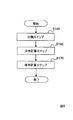
図1にこの発明の複数信号区間推定装置100の機能構成例を示す。図2に動作フローを示す。複数信号区間推定装置100は、周波数領域変換部11と、音声存在確率推定部12と、到来方向推定部13と、到来方向確率計算部14と、乗算部15とを具備する。周波数領域変換部11に入力される観測信号x(τ)は、複数のマイクロホンで収録された複数の音源からの音声信号であり、例えばサンプリング周波数16kHzで離散値化された信号である。図1では観測信号を離散値化するAD変換器については省略している。複数信号区間推定装置100は、例えばROM、RAM、CPU等で構成されるコンピュータに所定のプログラムが読み込まれて、CPUがそのプログラムを実行することで実現されるものである。
FIG. 1 shows an example of a functional configuration of a multiple signal section estimation apparatus 100 of the present invention. FIG. 2 shows an operation flow. The multiple signal section estimation device 100 includes a frequency
周波数領域変換部11は、離散値化された観測信号を、例えば512点毎に窓関数で切り出し、フーリエ変換などで周波数領域の信号に変換する(ステップS11、図2参照)。この場合、フレーム長は512/16kHz=32msである。音声存在確率推定部12は、各フレーム(τ)における音声の存在確率pv(τ)を推定する(ステップS12)。到来方向推定部13は、各フレームの各周波数成分についての音声到来方向q(f,τ)を推定する(ステップS13)。到来方向確率計算部14は、音声到来方向を分類して各音源に関する音声到来方向の分布を求め、各音源に関する音声到来方向確率pk(τ)を計算する(ステップS14)。乗算部15は、音声存在確率pv(τ)と、音声到来方向確率pk(τ)との積を計算して音源毎の発音確率Pk(τ)を出力する(ステップS15)。
The frequency
以上のように音声区間を音声存在確率として、また音声到来方向を各フレームで複数音源に関する音声到来方向確率として処理するのでフレームが欠損することが少ない。つまり音声信号の取りこぼしを少なくした複数信号区間推定装置が実現できる。以下、複数信号区間推定装置100の各部の動作を詳しく説明する。ただし、周波数領域変換部11と乗算部15については、従来技術で簡単に構成できるので、詳しい説明は省略する。
As described above, since the speech section is processed as the speech existence probability and the speech arrival direction is processed as the speech arrival direction probability for a plurality of sound sources in each frame, frames are rarely lost. That is, it is possible to realize a multi-signal section estimation device that reduces the missed voice signal. Hereinafter, the operation of each unit of the multiple signal section estimation apparatus 100 will be described in detail. However, since the frequency
〔音声存在確率推定部〕
図3に音声存在確率推定部12の機能ブロックを示す。音声存在確率推定部12は、GMMパラメータ記録部120と、カルマンフィルタ121と、GMM尤度計算部122と、単一ガウス分布尤度計算部123と、推移確率記録部124と、前向き確率算出部125と、前向き確率保持部126を備える。音声存在確率推定部12は、入力の特徴ベクトルを混合ガウス分布で表現したGMM(Gaussian Mixture model)を用いて、式(1)と(2)に示すように音声存在確率pv(τ)を前向き確率αj(τ)として算出するものである。
[Speech existence probability estimation unit]
FIG. 3 shows functional blocks of the speech existence

カルマンフィルタ121は、観測信号x(f,τ)とGMMパラメータを入力として、時刻τ−1における音声/非音声GMMから、時刻τにおける各ガウス分布(k番目)の平均値μjmkτと分散値Σjmkτを推定する。単一ガウス分布尤度計算部123は、ガウス分布の平均値μjmkτと分散値Σjmkτを入力として各ガウス分布の尤度bjk(τ)を式(3)で計算する。
The Kalman
GMM尤度計算部122は、各ガウス分布の尤度bjk(τ)と、重み係数ωjkを入力として音声GMMb1(τ)及び非音声GMMb0(τ)の尤度bj(τ)を式(4)で計算する。
The GMM
![]()
なお、音声存在確率pv(τ)を式(5)に示す演算で求めても良い。
![]()
Note that the speech existence probability p v (τ) may be obtained by the calculation shown in Expression (5).
〔参考文献〕J.Sohn,N.S.Kim and W.Sung,“A Statistical Model-Based Voice Activity Detection,IEEE Signal Processing letters”,vol.6,no.1,pp.1-3,1999.
(Reference) J. Sohn, NSKim and W. Sung, “A Statistical Model-Based Voice Activity Detection, IEEE Signal Processing letters”, vol. 6, no. 1, pp. 1-3, 1999.
〔到来方向推定部〕
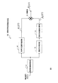
図4に到来方向推定部13と到来方向確率計算部14の機能構成例を示す。到来方向推定部13は、マイク間位相差計算部131と音源方向ベクトル計算部132を備える。マイク間位相差計算部131は、周波数領域に変換された観測信号x(f,τ)の各フレームτ、各周波数fにおけるマイク間位相差q´jj´を式(8)で計算する。
[Arrival Direction Estimator]
FIG. 4 shows a functional configuration example of the arrival
![]()
![]()
![]()
![]()
〔到来方向確率計算部〕
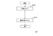
到来方向確率計算部14は、クラスタリング部140と、各クラスタの分布計算部160と、確率計算部170を備える。この実施例では、クラスタリング部140が、音源方向ベクトルq(f,τ)の各フレームの各周波数(f,τ)における水平角θ(f,τ)をオンラインクラスタリングする。到来方向確率計算部14の動作フローを図5に示す。到来方向確率計算過程(ステップS14、図2参照)は、クラスタリング部140が音源方向ベクトルとクラスタのセントロイドとの距離で音源方向ベクトルを分類する分類ステップ(ステップS140、図5参照)と、各クラスタの分布計算部が分類毎の音源方向ベクトルの分布を計算する分布計算ステップ(ステップS160)と、確率計算部170が分類毎の音源方向ベクトルの分布を、音源方向ベクトルの全体の分布で除して音声到来方向確率として計算する確率計算ステップ(ステップS170)とを含む。図6に分類ステップS140の詳細な動作フローを示して説明する。
[Arrival Direction Probability Calculator]
The arrival direction
<ステップS141>
まず、分類するグループの中心値であるセントロイドを更新する大きさである更新ステップサイズβと、グループ分けするための閾値zを設定する。更新ステップサイズβと閾値zは、この発明を実施する環境に応じて適宜実験的に定められる値である。
<ステップS142>
フレームτと周波数fを初期化(τ=1,f=1)する。
<ステップS143>
最初のフレームτ=1の最小周波数f=1の音源方向ベクトルq(f,τ)の水平角θ(f,τ)を、第1のセントロイドc1とする。
<ステップS144>
周波数fを次の周波数にインクリメントする。
<Step S141>
First, an update step size β that is a size for updating a centroid that is a central value of a group to be classified, and a threshold z for grouping are set. The update step size β and the threshold value z are values determined experimentally as appropriate according to the environment in which the present invention is implemented.
<Step S142>
The frame τ and the frequency f are initialized (τ = 1, f = 1).
<Step S143>
The horizontal angle θ (f, τ) of the sound source direction vector q (f, τ) with the minimum frequency f = 1 in the first frame τ = 1 is defined as a first centroid c 1 .
<Step S144>
The frequency f is incremented to the next frequency.
<ステップS145>
水平角θ(f,τ)に最も近い既存セントロイドckを見つけ、その番号をkとする。つまり式(11)で、クラスタリングする周波数成分の水平角に最も近いクラスタkを選択する。
<Step S145>
Find the existing centroid kk closest to the horizontal angle θ (f, τ) and let its number be k. That is, the cluster k that is closest to the horizontal angle of the frequency components to be clustered is selected using Equation (11).
![]()
ステップS145で求めた最も近いセントロイドckとθ(f,τ)の距離と閾値zを比較する。距離が閾値zより小さければ(ステップS146のYes)、θ(f,τ)も同方向(音源)からの周波数成分と判定してステップS147の処理を行う。距離が閾値zよりも大きければ(ステップS146のNo)、他の方向の音源からの周波数成分と判定してステップS149の処理を行う。
<ステップS147>
セントロイドckを式(12)で更新する。
![]()
The distance between the nearest centroid kk and θ (f, τ) obtained in step S145 and the threshold value z are compared. If the distance is smaller than the threshold value z (Yes in step S146), θ (f, τ) is also determined as a frequency component from the same direction (sound source), and the process in step S147 is performed. If the distance is larger than the threshold value z (No in step S146), the frequency component from the sound source in the other direction is determined and the process in step S149 is performed.
<Step S147>
The centroid ck is updated by the equation (12).
![]()
<ステップS148>
距離が閾値zより小さいので同方向(音源)からの周波数成分と判断し、その時間周波数(f,τ)にクラスタKのクラスタ番号を付与する。ここでは、ある時間周波数(f,τ)のクラスタ番号をC(f,τ)に保持する。
![]()
<Step S148>
Since the distance is smaller than the threshold value z, it is determined as a frequency component from the same direction (sound source), and the cluster number of the cluster K is given to the time frequency (f, τ). Here, the cluster number of a certain time frequency (f, τ) is held in C (f, τ).
<ステップS149>
距離が閾値zよりも大きいので、この音源方向ベクトルq(f,τ)は、他の方向の音源からの周波数成分と判定する(ステップS146のNo)。他の方向からの周波数成分として分類するために、max(k)+1番目の新しいクラスタを生成し、そのセントロイドをcmax(k)+1=θ(f,τ)として与える。
<ステップS150>
その時間周波数(f,τ)に新しいクラスタ番号を付与する。
<ステップS151>
周波数fが、最後の周波数か否かを判定する。最後の周波数で無い場合(ステップS151のNo)、周波数をインクリメント(ステップS154)してステップS145の動作に戻る。
<Step S149>
Since the distance is larger than the threshold value z, the sound source direction vector q (f, τ) is determined as a frequency component from a sound source in another direction (No in step S146). In order to classify as frequency components from other directions, a max (k) + 1-th new cluster is generated, and its centroid is given as c max (k) +1 = θ (f, τ).
<Step S150>
A new cluster number is assigned to the time frequency (f, τ).
<Step S151>
It is determined whether the frequency f is the last frequency. If it is not the last frequency (No in step S151), the frequency is incremented (step S154), and the operation returns to step S145.
<ステップS152>
周波数fが、最後の周波数の場合(ステップS151のYes)、フレームτが最後であるか否かを判定する。フレームτが最後の場合、クラスタリング動作を終了する(ステップS152のYes)。フレームτが最後で無い場合(ステップS152のNo)、フレームτをインクリメントすると共に周波数を初期化(ステップS155)してステップS145の動作に戻る。なお、メンバ数が少ないクラスタは除外しても良い(破線で示すステップS153)。
<Step S152>
When the frequency f is the last frequency (Yes in step S151), it is determined whether or not the frame τ is the last. If the frame τ is the last, the clustering operation is terminated (Yes in step S152). If the frame τ is not the last (No in step S152), the frame τ is incremented and the frequency is initialized (step S155), and the process returns to the operation in step S145. A cluster having a small number of members may be excluded (step S153 indicated by a broken line).
以上のように動作することで、音源方向ベクトルq(f,τ)の全てのフレーム、全ての周波数がクラスタリングされ、音源方向ベクトルq(f,τ)にクラスタ番号kが付与される。
クラスタリング部140で分類された音源方向ベクトルq(f,τ)の水平角θ(f,τ)の分布を、各クラスタの分布計算部160が計算する。各クラスタの分布計算部160は、式(13)を用いて各クラスタを平均値ck,分散σk 2の正規分布でモデル化する(ステップS160、図5参照)。
By operating as described above, all frames and all frequencies of the sound source direction vector q (f, τ) are clustered, and the cluster number k is assigned to the sound source direction vector q (f, τ).
The
分散σk 2は式(15)で計算する。
The variance σ k 2 is calculated by the equation (15).
![]()
![]()
次に到来方向確率pk(τ)を、クラスタリングされた音源方向ベクトルq(f,τ)の水平角θ(f,τ)の度数から求めるようにした実施例2を説明する。実施例2の到来方向確率計算部14´は、クラスタリング部140´と、確率計算部170´を備える(図4参照)。他の構成は実施例1と同じである。動作フローを図7に示す。
クラスタリング部140´は、ある時刻τまでに存在するクラスタのセントロイドckについて、式(19)に示す計算をして音源方向ベクトルq(f,τ)をクラスタリングする(ステップS140´)。
Next, a description will be given of a second embodiment in which the arrival direction probability p k (τ) is obtained from the frequency of the horizontal angle θ (f, τ) of the clustered sound source direction vector q (f, τ). The arrival direction
The clustering unit 140 ′ clusters the sound source direction vector q (f, τ) by performing the calculation shown in Equation (19) for the centroid ck of the cluster existing up to a certain time τ (step S140 ′).
確率計算部170´は、式(20)で到来方向確率pk(τ)を計算する(ステップS170´)。
The probability calculation unit 170 ′ calculates the arrival direction probability p k (τ) using Expression (20) (step S170 ′).
実施例3として雑音を抑圧するようにした到来方向確率計算部60の構成を図4に示して説明する。到来方向確率計算部60は、振幅計算部61を備える。他の構成は実施例1,2と同じである。動作フローを図8に示す。
振幅計算部61は、音源方向ベクトルq(f,τ)の時間周波数(f,τ)における正規化された振幅値a(f,τ)を式(21)で計算する(ステップS61)。
A configuration of the arrival direction probability calculation unit 60 configured to suppress noise as Example 3 will be described with reference to FIG. The arrival direction probability calculation unit 60 includes an
The
確率計算部62は、振幅値a(f,τ)を用いて到来方向確率pk(τ)を式(22)で算出する(ステップS170´)。
The probability calculation unit 62 calculates the arrival direction probability p k (τ) by using the amplitude value a (f, τ) by Expression (22) (step S170 ′).
この正規化された振幅値a(f,τ)を到来方向確率pk(τ)の算出の際に、式(22)に示すように考慮することで、雑音を音声として誤検出してしまうことを抑制することができる。
なお、式(22)は実施例2に振幅計算部61を設けた場合の式である。音源方向ベクトルの分布を正規分布として求めた実施例1に振幅計算部61を設けても、雑音を抑圧する効果が期待できる。
When this normalized amplitude value a (f, τ) is taken into account when calculating the arrival direction probability p k (τ), the noise is erroneously detected as speech. This can be suppressed.
Expression (22) is an expression in the case where the
〔シミュレーション結果〕
実施例2の複数信号区間推定装置の性能を確認するシミュレーションを行った。シミュ
レーション条件を簡単に説明する。図7にシミュレーションに用いた部屋の平面図を示す。奥行きのある部屋の幅側の一辺を、305cmの幅のパーテーションで仕切り、幅が約4mで奥行き約9.3mの部屋を形成した。この部屋の残響時間は約350msである。パーテーションの一方の隅にはパーソナルコンピュータ(PC)があり、そのファンノイズが本システムに対する雑音となった。パーテーション側に近い位置に長円形のテーブルを配置した。テーブルを挟んでパーテーション側に話者AとBの二人、反対側に話者CとDの二人を座らせた。そして4人の話者のほぼ中央付近の位置に3個のマイクロホンを、4cmの正三角形の頂点に位置するように配置した。
〔simulation result〕
A simulation for confirming the performance of the multiple signal section estimation apparatus of the second embodiment was performed. The simulation conditions will be briefly described. FIG. 7 shows a plan view of the room used for the simulation. One side of the width side of the deep room was partitioned by a 305 cm wide partition to form a room with a width of about 4 m and a depth of about 9.3 m. The reverberation time of this room is about 350 ms. There was a personal computer (PC) in one corner of the partition, and its fan noise became noise for this system. An oval table was placed near the partition side. Two speakers A and B sit on the partition side and two speakers C and D sit on the other side across the table. Then, three microphones were arranged at positions near the center of the four speakers so as to be located at the vertices of a 4 cm equilateral triangle.
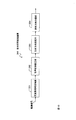
話者A〜Dの4名の会議を5分間、サンプリング周波数16kHz、フーリエ変換のフレーム長を64ms、フレームシフト長を32msとし、上記した式(16)の発話確率Pk(τ)が0.4以上となるクラスタkの方向の話者が話したと判定した。評価指標としては、DER=(誤受理・誤棄却・話者誤りの時間長)/全音声区間長×100[%(Diarization Error Rate)を利用した。 The conference of four speakers A to D is held for 5 minutes, the sampling frequency is 16 kHz, the Fourier transform frame length is 64 ms, the frame shift length is 32 ms, and the utterance probability P k (τ) of the above equation (16) is 0. It was determined that the speaker in the direction of cluster k, which is 4 or more, spoke. As an evaluation index, DER = (time length of false acceptance / false rejection / speaker error) / total speech interval length × 100 [% (Diarization Error Rate) was used.
ここで、誤受理(FAT:false alarm speaker time)は、誰も話していないにもかかわらず誰かが話していると判定した時間長である。誤棄却(MST:missed speaker time)は、誰かが話しているにもかかわらず話していないと判定した時間長である。話者誤り(SET:speaker error time)は、話者を誤って判定した時間長である。DER値は、小さい方が話者区間推定の精度が高いことを意味する。全てを[%]で表わす。表1に結果を示す。 Here, false alarm speaker time (FAT) is the length of time when it is determined that someone is speaking even though no one is speaking. Missed speaker time (MST) is the length of time that someone decides that they are speaking but not speaking. The speaker error time (SET) is the length of time that the speaker is erroneously determined. A smaller DER value means higher accuracy of speaker section estimation. All are expressed in [%]. Table 1 shows the results.
法では、特に誤棄却(MST)が大きく改善され、その結果としてDERの値が改善した。これは、フレーム毎に、音声区間と音声到来方向が、確率値として処理されること、及び各フレームで複数の方向を推定することにより音声区間が欠損することが少ないことによる。
以上述べたように、この発明の複数信号区間推定装置によれば、音声信号の取りこぼしを少なくした複数信号の区間推定を行うことができる。この発明の技術思想に基づく複数信号区間推定装置とその方法は、上述の実施形態に限定されるものではなく、この発明の趣旨を逸脱しない範囲で適宜変更が可能である。上記した装置及び方法において説明した処理は、記載の順に従って時系列に実行されるのみならず、処理を実行する装置の処理能力あるいは必要に応じて並列的にあるいは個別に実行されるとしてもよい。
例えば、音声存在確率pv(τ)と到来方向確率pk(τ)の一方を、計算を軽くする目的で、決定論的に算出するようにしても良い。一方を決定論的に算出しても、音声が在ると判定されたフレームにおいては、複数音源があれば複数方向の方向確率が計算されるので、そのフレーム内の複数の音源を取りこぼすことが従来法に比べて少なくなる。
As described above, according to the multiple signal section estimation apparatus of the present invention, it is possible to perform section estimation of a plurality of signals with less missing audio signals. The multiple signal section estimation device and method based on the technical idea of the present invention are not limited to the above-described embodiments, and can be appropriately changed without departing from the spirit of the present invention. The processes described in the above-described apparatus and method are not only executed in time series according to the order described, but may be executed in parallel or individually as required by the processing capability of the apparatus that executes the process. .
For example, one of the speech existence probability p v (τ) and the arrival direction probability p k (τ) may be calculated deterministically for the purpose of reducing the calculation. Even if one of them is calculated deterministically, the direction probability in multiple directions will be calculated if there are multiple sound sources in a frame that is determined to have sound, so multiple sound sources in that frame will be missed. Is less than the conventional method.
また、到来方向確率pk(τ)は、式(17)を満たす水平角θ(f,τ)が各周波数でth2個以上存在していればpk(τ)=1、そうでなければpk(τ)=0としても良い。また、クラスタリング部におけるセントロイドckは、予めそれぞれの音源の方向θkが分かっていればその角度をck=θkとして与えても良い。また、各フレーム、周波数(f,τ)における水平角θ(f,τ)ではなく、従来のGCC−PHAT法のように各フレームτ毎に1つだけ求めた水平角θ(τ)をオンラインクラスタリングし、そのセントロイドをckとして用いても良い。また、水平角θ(f,τ)を用いて音源の到来方向を分類する例で説明を行ったが、音源方向ベクトルq(f,τ)そのものを用いて分類するようにしても良い。 The arrival direction probability p k (τ) is p k (τ) = 1 if there are th 2 or more horizontal angles θ (f, τ) satisfying the equation (17) at each frequency. For example, p k (τ) = 0 may be set. Further, the centroid c k in the clustering unit may be given as c k = θ k if the direction θ k of each sound source is known in advance. Also, instead of the horizontal angle θ (f, τ) at each frame and frequency (f, τ), only one horizontal angle θ (τ) obtained for each frame τ as in the conventional GCC-PHAT method is online. Clustering may be performed, and the centroid may be used as ck . In addition, although an example in which the arrival direction of the sound source is classified using the horizontal angle θ (f, τ) has been described, the sound source direction vector q (f, τ) itself may be used for classification.
また、上記装置における処理手段をコンピュータによって実現する場合、各装置が有すべき機能の処理内容はプログラムによって記述される。そして、このプログラムをコンピュータで実行することにより、各装置における処理手段がコンピュータ上で実現される。
この処理内容を記述したプログラムは、コンピュータで読み取り可能な記録媒体に記録しておくことができる。コンピュータで読み取り可能な記録媒体としては、例えば、磁気記録装置、光ディスク、光磁気記録媒体、半導体メモリ等どのようなものでもよい。具体的には、例えば、磁気記録装置として、ハードディスク装置、フレキシブルディスク、磁気テープ等を、光ディスクとして、DVD(Digital Versatile Disc)、DVD-RAM(Random Access Memory)、CD-ROM(Compact Disc Read Only Memory)、CD-R(Recordable)/RW(ReWritable)等を、光磁気記録媒体として、MO(Magneto Optical disc)等を、半導体メモリとしてフラッシュメモリー等を用いることができる。
Further, when the processing means in the above apparatus is realized by a computer, the processing contents of functions that each apparatus should have are described by a program. Then, by executing this program on the computer, the processing means in each apparatus is realized on the computer.
The program describing the processing contents can be recorded on a computer-readable recording medium. As the computer-readable recording medium, for example, any recording medium such as a magnetic recording device, an optical disk, a magneto-optical recording medium, and a semiconductor memory may be used. Specifically, for example, as a magnetic recording device, a hard disk device, a flexible disk, a magnetic tape, etc., and as an optical disk, a DVD (Digital Versatile Disc), a DVD-RAM (Random Access Memory), a CD-ROM (Compact Disc Read Only) Memory), CD-R (Recordable) / RW (ReWritable), etc. can be used as magneto-optical recording media, MO (Magneto Optical disc) can be used, and flash memory can be used as semiconductor memory.
また、このプログラムの流通は、例えば、そのプログラムを記録したDVD、CD−ROM等の可搬型記録媒体を販売、譲渡、貸与等することによって行う。さらに、このプログラムをサーバコンピュータの記録装置に格納しておき、ネットワークを介して、サーバコンピュータから他のコンピュータにそのプログラムを転送することにより、このプログラムを流通させる構成としてもよい。
また、各手段は、コンピュータ上で所定のプログラムを実行させることにより構成することにしてもよいし、これらの処理内容の少なくとも一部をハードウェア的に実現することとしてもよい。
The program is distributed by selling, transferring, or lending a portable recording medium such as a DVD or CD-ROM in which the program is recorded. Further, the program may be distributed by storing the program in a recording device of a server computer and transferring the program from the server computer to another computer via a network.
Each means may be configured by executing a predetermined program on a computer, or at least a part of these processing contents may be realized by hardware.
Claims (10)
上記音声信号を、フレーム毎に周波数領域の信号に変換する周波数領域変換部と、
上記フレーム毎の周波数領域の信号からフレーム毎に音声の存在確率を推定する音声存在確率推定部と、
上記フレーム毎の周波数領域の信号からフレーム毎に各周波数成分についての音声到来方向を推定する到来方向推定部と、
上記各周波数成分についての音声到来方向からフレーム毎に上記各音源に関する音声到来方向確率を計算する到来方向確率計算部と、
上記音声存在確率と、上記音声到来方向確率との積を計算して上記各フレームにおける音源毎の存在確率を出力する乗算部と、
上記音源毎の存在確率が所定の閾値を越える場合に、当該フレームを当該音源の信号区間と判定する判定部と、
を具備する信号区間推定装置。 A signal section estimation device for estimating a section in which a signal is emitted from each sound source from sound signals from a plurality of sound sources recorded by a plurality of microphones,
A frequency domain converter that converts the audio signal into a frequency domain signal for each frame;
A speech presence probability estimation unit for estimating the existence probability of speech for each frame from the signal in the frequency domain for each said frame,
A direction-of-arrival estimation unit that estimates a voice arrival direction for each frequency component for each frame from a signal in a frequency domain for each frame;
A direction-of-arrival probability calculation unit that calculates a speech direction-of-arrival probability for each sound source for each frame from the direction of speech arrival for each frequency component ;
A multiplication unit that calculates a product of the voice presence probability and the voice arrival direction probability and outputs a presence probability for each sound source in each frame;
A determination unit that determines the frame as a signal section of the sound source when the existence probability for each sound source exceeds a predetermined threshold;
Signal interval estimation device you comprises a.
上記到来方向確率計算部は、クラスタリング部と、各クラスタの分布計算部と、確率計算部を備え、
上記クラスタリング部は、上記フレーム毎に計算された各周波数での音源方向をクラスタリングすることにより、上記音源方向をクラスタに分けるものであり、
上記各クラスタの分布計算部は、上記クラスタリング部で得られた各クラスタの上記音源方向の分布を計算するものであり、
上記確率計算部は、上記クラスタ毎の上記音源方向の分布を、上記音源方向の全体の分布で正規化して音声到来方向確率として出力するものである、
ことを特徴とする信号区間推定装置。 In signal interval estimation apparatus according to claim 1,
The arrival direction probability calculation unit includes a clustering unit, a distribution calculation unit for each cluster, and a probability calculation unit,
The clustering unit, by clustering sound source direction for each frequency calculated for each of the frames, a shall divide the sound source direction to the cluster,
Distribution calculation unit of each cluster is to calculate the sound source direction distribution of direction of each cluster obtained by the clustering unit,
The probability calculation unit, the sound source direction distribution of direction of each said cluster, and outputs it as sound arrival direction probability normalized to the overall distribution of the sound source Direction,
Signal interval estimation device you wherein a.
上記到来方向確率計算部は、クラスタリング部と、確率計算部を備え、
上記クラスタリング部は、上記フレーム毎に計算された各周波数での音源方向と閾値との距離で上記音源方向をクラスタリングするものであり、
上記確率計算部は、上記クラスタの各メンバ数を上記音源方向の全体のメンバ数で除した値を音声到来方向確率として出力するものであることを特徴とする信号区間推定装置。 In signal interval estimation apparatus according to claim 1,
The arrival direction probability calculation unit includes a clustering unit and a probability calculation unit,
The clustering section is for clustering the sound source direction by a distance between the sound source Direction and thresholds at each frequency that is calculated for each said frame,
The probability calculation section signal interval estimation device you characterized in that for outputting a value of the number of each member divided by the number of members the whole of the sound source Direction of the cluster as a sound arrival direction probability.
上記到来方向確率計算部は、上記各フレーム、各周波数における正規化された振幅値を計算する振幅計算部を備え、
上記音声到来方向確率を計算する際に、上記正規化された振幅値を重み係数として用いることを特徴とする信号区間推定装置。 In signal interval estimation apparatus according to any one of claims 1 to 3,
The arrival direction probability calculation unit includes an amplitude calculation unit for calculating a normalized amplitude value in each frame and each frequency,
When calculating the sound arrival direction probability, signal interval estimation device you characterized by using the above-described normalized amplitude value as a weighting factor.
周波数領域変換部が、上記音声信号を、フレーム毎に周波数領域の信号に変換する周波数領域過程と、
音声存在確率推定部が、上記フレーム毎の周波数領域の信号からフレーム毎に音声存在確率を推定する音声存在確率推定過程と、
到来方向推定部が、上記フレーム毎の周波数領域の信号からフレーム毎に各周波数成分についての音声到来方向を推定する到来方向推定過程と、
到来方向確率計算部が、上記各周波数成分についての音声到来方向からフレーム毎に上記各音源に関する音声到来方向確率を計算する到来方向確率計算過程と、
乗算部が、上記音声存在確率と、上記音声到来方向確率との積を計算して上記各フレームにおける音源毎の存在確率を出力する乗算過程と、
判定部が、上記音源毎の存在確率が所定の閾値を越える場合に、当該フレームを当該音源の信号区間と判定する判定過程と、
を含む信号区間推定方法。 A signal section estimation method for estimating a section in which a signal is emitted from each sound source from sound signals from a plurality of sound sources recorded by a plurality of microphones,
Frequency domain transform section, and the frequency domain process of converting the audio signal into a frequency domain signal for each frame,
Speech presence probability estimation unit, and a speech presence probability estimating step of estimating the speech presence probability for each frame from the signal in the frequency domain for each said frame,
A direction of arrival estimation process in which a direction of arrival estimation unit estimates a voice arrival direction for each frequency component for each frame from the frequency domain signal for each frame;
An arrival direction probability calculating unit calculates an arrival direction probability for each sound source for each frame from the arrival direction of the sound for each frequency component ;
A multiplication unit that calculates a product of the speech existence probability and the speech arrival direction probability and outputs a presence probability for each sound source in each frame;
A determination process in which the determination unit determines that the frame is a signal section of the sound source when the existence probability for each sound source exceeds a predetermined threshold;
Including signal interval estimation methods.
上記到来方向確率計算過程は、クラスタリング部が、上記フレーム毎に計算された各周波数での音源方向をクラスタリングすることにより、上記音源方向をクラスタに分ける分類ステップと、
各クラスタの分布計算部が、上記クラスタの上記音源方向の分布を計算する分布計算ステップと、
確率計算部が、上記クラスタ毎の上記音源方向の分布を、上記音源方向の全体の分布で正規化して音声到来方向確率として計算する確率計算ステップと、
を含むことを特徴とする信号区間推定方法。 In signal interval estimation method according to claim 5,
The direction of arrival probability calculation process, the clustering section, by clustering sound source direction for each frequency calculated for each of the frames, a classification step of Ru divide the sound source direction to the cluster,
Distribution calculation unit of each cluster, the distribution calculation step of calculating the sound source direction distribution direction of the cluster,
Probability calculation unit, the sound source direction distribution of direction of each said cluster, and the probability calculating step of calculating a voice arrival direction probability normalized to the overall distribution of the sound source Direction,
Signal interval estimation how to comprising a.
上記到来方向確率計算過程は、クラスタリング部が、上記フレーム毎に計算された各周波数での音源方向をクラスタリングする分類ステップと、
確率計算部が、上記クラスタの各メンバ数を上記音源方向の全体のメンバ数で除した値を音声到来方向確率として計算する確率計算ステップと、
を含むことを特徴とする信号区間推定方法。 In signal interval estimation method according to claim 5,
The direction-of-arrival probability calculation process includes a classification step in which a clustering unit clusters sound source directions at each frequency calculated for each frame;
Probability calculation portion, and the probability calculating step of calculating a voice arrival direction probability values the number of each member divided by the number of members the whole of the sound source Direction of the cluster,
Signal interval estimation how to comprising a.
上記到来方向確率計算過程は、振幅計算部が、上記各フレーム、各周波数における正規化された振幅値を計算する振幅計算ステップを含み、
上記正規化された振幅値を重み係数として用いて上記音声到来方向確率を計算することを特徴とする信号区間推定方法。 In signal interval estimation method according to any one of claims 5 to 7,
The arrival direction probability calculation process includes an amplitude calculation step in which an amplitude calculation unit calculates a normalized amplitude value in each frame and each frequency,
Signal interval estimation how to and calculating the sound arrival direction probability using the normalized amplitude value as a weighting factor.
Priority Applications (1)
| Application Number | Priority Date | Filing Date | Title |
|---|---|---|---|
| JP2008119717A JP4875656B2 (en) | 2008-05-01 | 2008-05-01 | Signal section estimation device and method, program, and recording medium |
Applications Claiming Priority (1)
| Application Number | Priority Date | Filing Date | Title |
|---|---|---|---|
| JP2008119717A JP4875656B2 (en) | 2008-05-01 | 2008-05-01 | Signal section estimation device and method, program, and recording medium |
Publications (2)
| Publication Number | Publication Date |
|---|---|
| JP2009271183A JP2009271183A (en) | 2009-11-19 |
| JP4875656B2 true JP4875656B2 (en) | 2012-02-15 |
Family
ID=41437810
Family Applications (1)
| Application Number | Title | Priority Date | Filing Date |
|---|---|---|---|
| JP2008119717A Expired - Fee Related JP4875656B2 (en) | 2008-05-01 | 2008-05-01 | Signal section estimation device and method, program, and recording medium |
Country Status (1)
| Country | Link |
|---|---|
| JP (1) | JP4875656B2 (en) |
Families Citing this family (13)
| Publication number | Priority date | Publication date | Assignee | Title |
|---|---|---|---|---|
| US9055371B2 (en) | 2010-11-19 | 2015-06-09 | Nokia Technologies Oy | Controllable playback system offering hierarchical playback options |
| US9456289B2 (en) | 2010-11-19 | 2016-09-27 | Nokia Technologies Oy | Converting multi-microphone captured signals to shifted signals useful for binaural signal processing and use thereof |
| US9313599B2 (en) | 2010-11-19 | 2016-04-12 | Nokia Technologies Oy | Apparatus and method for multi-channel signal playback |
| JP2012149906A (en) * | 2011-01-17 | 2012-08-09 | Mitsubishi Electric Corp | Sound source position estimation device, sound source position estimation method and sound source position estimation program |
| JP5668553B2 (en) * | 2011-03-18 | 2015-02-12 | 富士通株式会社 | Voice erroneous detection determination apparatus, voice erroneous detection determination method, and program |
| US9285452B2 (en) * | 2011-11-17 | 2016-03-15 | Nokia Technologies Oy | Spatial visual effect creation and display such as for a screensaver |
| CN108810744A (en) | 2012-04-05 | 2018-11-13 | 诺基亚技术有限公司 | Space audio flexible captures equipment |
| JP6240995B2 (en) * | 2013-01-15 | 2017-12-06 | 株式会社国際電気通信基礎技術研究所 | Mobile object, acoustic source map creation system, and acoustic source map creation method |
| WO2014162171A1 (en) | 2013-04-04 | 2014-10-09 | Nokia Corporation | Visual audio processing apparatus |
| US9706324B2 (en) | 2013-05-17 | 2017-07-11 | Nokia Technologies Oy | Spatial object oriented audio apparatus |
| JP6158006B2 (en) | 2013-09-17 | 2017-07-05 | 株式会社東芝 | Audio processing apparatus, method, and program |
| JP6740658B2 (en) * | 2016-03-24 | 2020-08-19 | 日本電気株式会社 | Device, method and program for passive sonar |
| JP2019008274A (en) * | 2017-06-26 | 2019-01-17 | フェアリーデバイセズ株式会社 | Voice information processing system, control method of voice information processing system, program of voice information processing system and storage medium |
Family Cites Families (1)
| Publication number | Priority date | Publication date | Assignee | Title |
|---|---|---|---|---|
| JP2007085734A (en) * | 2005-09-16 | 2007-04-05 | Research Organization Of Information & Systems | Sound source direction detection device and method |
-
2008
- 2008-05-01 JP JP2008119717A patent/JP4875656B2/en not_active Expired - Fee Related
Also Published As
| Publication number | Publication date |
|---|---|
| JP2009271183A (en) | 2009-11-19 |
Similar Documents
| Publication | Publication Date | Title |
|---|---|---|
| JP4875656B2 (en) | Signal section estimation device and method, program, and recording medium | |
| JP4964204B2 (en) | Multiple signal section estimation device, multiple signal section estimation method, program thereof, and recording medium | |
| US8554562B2 (en) | Method and system for speaker diarization | |
| US9818428B2 (en) | Extraction of target speeches | |
| JP4746533B2 (en) | Multi-sound source section determination method, method, program and recording medium thereof | |
| JP5842056B2 (en) | Noise estimation device, noise estimation method, noise estimation program, and recording medium | |
| JP5568530B2 (en) | Sound source separation device, method and program thereof | |
| JP6464005B2 (en) | Noise suppression speech recognition apparatus and program thereof | |
| US11900949B2 (en) | Signal extraction system, signal extraction learning method, and signal extraction learning program | |
| JP4891801B2 (en) | Multi-signal enhancement apparatus, method, program, and recording medium thereof | |
| JP2018063313A (en) | The number of speakers estimation device, the number of speakers estimation method, and program | |
| JP4856662B2 (en) | Noise removing apparatus, method thereof, program thereof and recording medium | |
| JP5351856B2 (en) | Sound source parameter estimation device, sound source separation device, method thereof, program, and storage medium | |
| JP5974901B2 (en) | Sound segment classification device, sound segment classification method, and sound segment classification program | |
| JP5994639B2 (en) | Sound section detection device, sound section detection method, and sound section detection program | |
| JP2016143042A (en) | Noise removal system and noise removal program | |
| KR101658001B1 (en) | Online target-speech extraction method for robust automatic speech recognition | |
| JP6724290B2 (en) | Sound processing device, sound processing method, and program | |
| JP2010130411A (en) | Apparatus and method for estimating multiple signal sections, and program | |
| JP2013186383A (en) | Sound source separation device, sound source separation method and program | |
| JP2019184747A (en) | Signal analyzer, signal analysis method, and signal analysis program | |
| JP6059112B2 (en) | Sound source separation device, method and program thereof | |
| JP2018040880A (en) | Sound source separation device, sound source separation method and sound source separation program | |
| JP5044581B2 (en) | Multiple signal emphasis apparatus, method and program | |
| JP5457999B2 (en) | Noise suppressor, method and program thereof |
Legal Events
| Date | Code | Title | Description |
|---|---|---|---|
| A621 | Written request for application examination |
Free format text: JAPANESE INTERMEDIATE CODE: A621 Effective date: 20100726 |
|
| RD03 | Notification of appointment of power of attorney |
Free format text: JAPANESE INTERMEDIATE CODE: A7423 Effective date: 20110729 |
|
| A131 | Notification of reasons for refusal |
Free format text: JAPANESE INTERMEDIATE CODE: A131 Effective date: 20110906 |
|
| A521 | Request for written amendment filed |
Free format text: JAPANESE INTERMEDIATE CODE: A523 Effective date: 20111018 |
|
| TRDD | Decision of grant or rejection written | ||
| A01 | Written decision to grant a patent or to grant a registration (utility model) |
Free format text: JAPANESE INTERMEDIATE CODE: A01 Effective date: 20111115 |
|
| A01 | Written decision to grant a patent or to grant a registration (utility model) |
Free format text: JAPANESE INTERMEDIATE CODE: A01 |
|
| A61 | First payment of annual fees (during grant procedure) |
Free format text: JAPANESE INTERMEDIATE CODE: A61 Effective date: 20111125 |
|
| FPAY | Renewal fee payment (event date is renewal date of database) |
Free format text: PAYMENT UNTIL: 20141202 Year of fee payment: 3 |
|
| R150 | Certificate of patent or registration of utility model |
Ref document number: 4875656 Country of ref document: JP Free format text: JAPANESE INTERMEDIATE CODE: R150 Free format text: JAPANESE INTERMEDIATE CODE: R150 |
|
| S531 | Written request for registration of change of domicile |
Free format text: JAPANESE INTERMEDIATE CODE: R313531 |
|
| R350 | Written notification of registration of transfer |
Free format text: JAPANESE INTERMEDIATE CODE: R350 |
|
| LAPS | Cancellation because of no payment of annual fees |