JP4865920B2 - Permanent magnet and method for manufacturing permanent magnet - Google Patents
Permanent magnet and method for manufacturing permanent magnet Download PDFInfo
- Publication number
- JP4865920B2 JP4865920B2 JP2011069074A JP2011069074A JP4865920B2 JP 4865920 B2 JP4865920 B2 JP 4865920B2 JP 2011069074 A JP2011069074 A JP 2011069074A JP 2011069074 A JP2011069074 A JP 2011069074A JP 4865920 B2 JP4865920 B2 JP 4865920B2
- Authority
- JP
- Japan
- Prior art keywords
- magnet
- permanent magnet
- organometallic compound
- sintering
- magnet powder
- Prior art date
- Legal status (The legal status is an assumption and is not a legal conclusion. Google has not performed a legal analysis and makes no representation as to the accuracy of the status listed.)
- Expired - Fee Related
Links
- 238000004519 manufacturing process Methods 0.000 title claims description 54
- 238000000034 method Methods 0.000 title claims description 45
- 239000002245 particle Substances 0.000 claims description 142
- 239000000843 powder Substances 0.000 claims description 116
- 238000005245 sintering Methods 0.000 claims description 116
- 150000002902 organometallic compounds Chemical class 0.000 claims description 83
- 239000013078 crystal Substances 0.000 claims description 59
- 238000001354 calcination Methods 0.000 claims description 54
- 239000001257 hydrogen Substances 0.000 claims description 45
- 229910052739 hydrogen Inorganic materials 0.000 claims description 45
- 238000010438 heat treatment Methods 0.000 claims description 41
- UFHFLCQGNIYNRP-UHFFFAOYSA-N Hydrogen Chemical compound [H][H] UFHFLCQGNIYNRP-UHFFFAOYSA-N 0.000 claims description 35
- 229910052750 molybdenum Inorganic materials 0.000 claims description 31
- 229910052715 tantalum Inorganic materials 0.000 claims description 31
- 229910052719 titanium Inorganic materials 0.000 claims description 31
- 229910052721 tungsten Inorganic materials 0.000 claims description 31
- 229910052720 vanadium Inorganic materials 0.000 claims description 31
- 229910052726 zirconium Inorganic materials 0.000 claims description 31
- 229910052751 metal Inorganic materials 0.000 claims description 27
- 239000002184 metal Substances 0.000 claims description 27
- 238000000465 moulding Methods 0.000 claims description 25
- 239000002994 raw material Substances 0.000 claims description 22
- 125000000217 alkyl group Chemical group 0.000 claims description 19
- 125000004432 carbon atom Chemical group C* 0.000 claims description 12
- 238000010298 pulverizing process Methods 0.000 claims description 11
- 239000004215 Carbon black (E152) Substances 0.000 claims description 8
- 229930195733 hydrocarbon Natural products 0.000 claims description 8
- 150000002430 hydrocarbons Chemical class 0.000 claims description 8
- 125000001424 substituent group Chemical group 0.000 claims description 8
- 239000010955 niobium Substances 0.000 description 76
- 230000005291 magnetic effect Effects 0.000 description 56
- QVGXLLKOCUKJST-UHFFFAOYSA-N atomic oxygen Chemical compound [O] QVGXLLKOCUKJST-UHFFFAOYSA-N 0.000 description 39
- 239000001301 oxygen Substances 0.000 description 39
- 229910052760 oxygen Inorganic materials 0.000 description 39
- 239000010936 titanium Substances 0.000 description 29
- 230000009467 reduction Effects 0.000 description 21
- 230000008569 process Effects 0.000 description 19
- 239000003870 refractory metal Substances 0.000 description 19
- 150000001875 compounds Chemical class 0.000 description 18
- 229910052758 niobium Inorganic materials 0.000 description 17
- 230000003993 interaction Effects 0.000 description 16
- 239000012071 phase Substances 0.000 description 15
- 239000007789 gas Substances 0.000 description 13
- XEEYBQQBJWHFJM-UHFFFAOYSA-N iron Substances [Fe] XEEYBQQBJWHFJM-UHFFFAOYSA-N 0.000 description 13
- 230000004907 flux Effects 0.000 description 12
- 230000005415 magnetization Effects 0.000 description 12
- 230000003647 oxidation Effects 0.000 description 12
- 238000007254 oxidation reaction Methods 0.000 description 12
- 238000001556 precipitation Methods 0.000 description 11
- 230000005381 magnetic domain Effects 0.000 description 10
- 229910001172 neodymium magnet Inorganic materials 0.000 description 10
- 229910052799 carbon Inorganic materials 0.000 description 9
- 230000000052 comparative effect Effects 0.000 description 9
- 229910044991 metal oxide Inorganic materials 0.000 description 9
- 150000004706 metal oxides Chemical class 0.000 description 9
- XKRFYHLGVUSROY-UHFFFAOYSA-N Argon Chemical compound [Ar] XKRFYHLGVUSROY-UHFFFAOYSA-N 0.000 description 8
- OKTJSMMVPCPJKN-UHFFFAOYSA-N Carbon Chemical compound [C] OKTJSMMVPCPJKN-UHFFFAOYSA-N 0.000 description 8
- 239000003966 growth inhibitor Substances 0.000 description 8
- 239000000203 mixture Substances 0.000 description 8
- 239000003960 organic solvent Substances 0.000 description 7
- 239000000243 solution Substances 0.000 description 7
- 238000001228 spectrum Methods 0.000 description 7
- 238000010586 diagram Methods 0.000 description 6
- 125000001183 hydrocarbyl group Chemical group 0.000 description 6
- 238000002844 melting Methods 0.000 description 6
- 230000008018 melting Effects 0.000 description 6
- 239000002002 slurry Substances 0.000 description 6
- 150000004703 alkoxides Chemical class 0.000 description 5
- 239000011261 inert gas Substances 0.000 description 5
- CGAFRZVAXRQUEI-UHFFFAOYSA-N niobium(5+);propan-1-olate Chemical compound [Nb+5].CCC[O-].CCC[O-].CCC[O-].CCC[O-].CCC[O-] CGAFRZVAXRQUEI-UHFFFAOYSA-N 0.000 description 5
- 229910052786 argon Inorganic materials 0.000 description 4
- 230000008901 benefit Effects 0.000 description 4
- 230000007423 decrease Effects 0.000 description 4
- 238000010304 firing Methods 0.000 description 4
- 229910052742 iron Inorganic materials 0.000 description 4
- IJGRMHOSHXDMSA-UHFFFAOYSA-N Atomic nitrogen Chemical compound N#N IJGRMHOSHXDMSA-UHFFFAOYSA-N 0.000 description 3
- 230000015572 biosynthetic process Effects 0.000 description 3
- 229910052796 boron Inorganic materials 0.000 description 3
- 238000005266 casting Methods 0.000 description 3
- 238000006356 dehydrogenation reaction Methods 0.000 description 3
- 229910001873 dinitrogen Inorganic materials 0.000 description 3
- 230000005284 excitation Effects 0.000 description 3
- 229910000765 intermetallic Inorganic materials 0.000 description 3
- 150000002736 metal compounds Chemical class 0.000 description 3
- NBTOZLQBSIZIKS-UHFFFAOYSA-N methoxide Chemical compound [O-]C NBTOZLQBSIZIKS-UHFFFAOYSA-N 0.000 description 3
- GUCVJGMIXFAOAE-UHFFFAOYSA-N niobium atom Chemical compound [Nb] GUCVJGMIXFAOAE-UHFFFAOYSA-N 0.000 description 3
- 230000009257 reactivity Effects 0.000 description 3
- 238000001291 vacuum drying Methods 0.000 description 3
- FIPWRIJSWJWJAI-UHFFFAOYSA-N Butyl carbitol 6-propylpiperonyl ether Chemical compound C1=C(CCC)C(COCCOCCOCCCC)=CC2=C1OCO2 FIPWRIJSWJWJAI-UHFFFAOYSA-N 0.000 description 2
- 229910052692 Dysprosium Inorganic materials 0.000 description 2
- 229910052771 Terbium Inorganic materials 0.000 description 2
- 229910052782 aluminium Inorganic materials 0.000 description 2
- DINQVNXOZUORJS-UHFFFAOYSA-N butan-1-olate;niobium(5+) Chemical compound [Nb+5].CCCC[O-].CCCC[O-].CCCC[O-].CCCC[O-].CCCC[O-] DINQVNXOZUORJS-UHFFFAOYSA-N 0.000 description 2
- 229910052802 copper Inorganic materials 0.000 description 2
- 238000005262 decarbonization Methods 0.000 description 2
- 238000000354 decomposition reaction Methods 0.000 description 2
- 230000000694 effects Effects 0.000 description 2
- HHFAWKCIHAUFRX-UHFFFAOYSA-N ethoxide Chemical compound CC[O-] HHFAWKCIHAUFRX-UHFFFAOYSA-N 0.000 description 2
- 239000003302 ferromagnetic material Substances 0.000 description 2
- 239000010419 fine particle Substances 0.000 description 2
- 150000002431 hydrogen Chemical class 0.000 description 2
- 230000001678 irradiating effect Effects 0.000 description 2
- 239000000463 material Substances 0.000 description 2
- -1 neodymium (III) acetylacetonate trihydrate Chemical class 0.000 description 2
- QEFYFXOXNSNQGX-UHFFFAOYSA-N neodymium atom Chemical compound [Nd] QEFYFXOXNSNQGX-UHFFFAOYSA-N 0.000 description 2
- ZTILUDNICMILKJ-UHFFFAOYSA-N niobium(v) ethoxide Chemical compound CCO[Nb](OCC)(OCC)(OCC)OCC ZTILUDNICMILKJ-UHFFFAOYSA-N 0.000 description 2
- 230000000149 penetrating effect Effects 0.000 description 2
- 229960005235 piperonyl butoxide Drugs 0.000 description 2
- IKNCGYCHMGNBCP-UHFFFAOYSA-N propan-1-olate Chemical compound CCC[O-] IKNCGYCHMGNBCP-UHFFFAOYSA-N 0.000 description 2
- OGHBATFHNDZKSO-UHFFFAOYSA-N propan-2-olate Chemical compound CC(C)[O-] OGHBATFHNDZKSO-UHFFFAOYSA-N 0.000 description 2
- 238000000197 pyrolysis Methods 0.000 description 2
- 239000000523 sample Substances 0.000 description 2
- 238000005979 thermal decomposition reaction Methods 0.000 description 2
- QBKTXRLYEHZACW-UHFFFAOYSA-K 2-ethylhexanoate;neodymium(3+) Chemical compound [Nd+3].CCCCC(CC)C([O-])=O.CCCCC(CC)C([O-])=O.CCCCC(CC)C([O-])=O QBKTXRLYEHZACW-UHFFFAOYSA-K 0.000 description 1
- ZOKXTWBITQBERF-UHFFFAOYSA-N Molybdenum Chemical compound [Mo] ZOKXTWBITQBERF-UHFFFAOYSA-N 0.000 description 1
- 229910052779 Neodymium Inorganic materials 0.000 description 1
- 229910019142 PO4 Inorganic materials 0.000 description 1
- OAICVXFJPJFONN-UHFFFAOYSA-N Phosphorus Chemical compound [P] OAICVXFJPJFONN-UHFFFAOYSA-N 0.000 description 1
- YZCKVEUIGOORGS-IGMARMGPSA-N Protium Chemical compound [1H] YZCKVEUIGOORGS-IGMARMGPSA-N 0.000 description 1
- RTAQQCXQSZGOHL-UHFFFAOYSA-N Titanium Chemical compound [Ti] RTAQQCXQSZGOHL-UHFFFAOYSA-N 0.000 description 1
- QCWXUUIWCKQGHC-UHFFFAOYSA-N Zirconium Chemical compound [Zr] QCWXUUIWCKQGHC-UHFFFAOYSA-N 0.000 description 1
- 229910045601 alloy Inorganic materials 0.000 description 1
- 239000000956 alloy Substances 0.000 description 1
- 229910052787 antimony Inorganic materials 0.000 description 1
- 125000004429 atom Chemical group 0.000 description 1
- 229910052793 cadmium Inorganic materials 0.000 description 1
- 150000001721 carbon Chemical group 0.000 description 1
- 239000003245 coal Substances 0.000 description 1
- 230000006866 deterioration Effects 0.000 description 1
- 230000002542 deteriorative effect Effects 0.000 description 1
- 238000009792 diffusion process Methods 0.000 description 1
- KBQHZAAAGSGFKK-UHFFFAOYSA-N dysprosium atom Chemical compound [Dy] KBQHZAAAGSGFKK-UHFFFAOYSA-N 0.000 description 1
- 238000005868 electrolysis reaction Methods 0.000 description 1
- 230000006870 function Effects 0.000 description 1
- 229910052733 gallium Inorganic materials 0.000 description 1
- 229910052732 germanium Inorganic materials 0.000 description 1
- 238000000227 grinding Methods 0.000 description 1
- 238000001513 hot isostatic pressing Methods 0.000 description 1
- 150000004677 hydrates Chemical class 0.000 description 1
- 230000006872 improvement Effects 0.000 description 1
- 229910052738 indium Inorganic materials 0.000 description 1
- 238000002347 injection Methods 0.000 description 1
- 239000007924 injection Substances 0.000 description 1
- 229910052741 iridium Inorganic materials 0.000 description 1
- 238000004898 kneading Methods 0.000 description 1
- 229910052747 lanthanoid Inorganic materials 0.000 description 1
- 150000002602 lanthanoids Chemical class 0.000 description 1
- 239000007791 liquid phase Substances 0.000 description 1
- 230000005389 magnetism Effects 0.000 description 1
- 230000007246 mechanism Effects 0.000 description 1
- 239000002923 metal particle Substances 0.000 description 1
- 229910052752 metalloid Inorganic materials 0.000 description 1
- 150000002738 metalloids Chemical class 0.000 description 1
- 150000002739 metals Chemical class 0.000 description 1
- 238000002156 mixing Methods 0.000 description 1
- 239000011733 molybdenum Substances 0.000 description 1
- HZHUIQPXRWTHNF-UHFFFAOYSA-N neodymium(3+);propan-2-olate Chemical compound [Nd+3].CC(C)[O-].CC(C)[O-].CC(C)[O-] HZHUIQPXRWTHNF-UHFFFAOYSA-N 0.000 description 1
- GMQPBTKWMZBSCT-UHFFFAOYSA-K neodymium(3+);triacetate;hydrate Chemical compound O.[Nd+3].CC([O-])=O.CC([O-])=O.CC([O-])=O GMQPBTKWMZBSCT-UHFFFAOYSA-K 0.000 description 1
- WYRSPTDNOIZOGA-UHFFFAOYSA-K neodymium(3+);trifluoromethanesulfonate Chemical compound [Nd+3].[O-]S(=O)(=O)C(F)(F)F.[O-]S(=O)(=O)C(F)(F)F.[O-]S(=O)(=O)C(F)(F)F WYRSPTDNOIZOGA-UHFFFAOYSA-K 0.000 description 1
- 229910052759 nickel Inorganic materials 0.000 description 1
- 125000000962 organic group Chemical group 0.000 description 1
- 230000005449 particle theory Effects 0.000 description 1
- NBIIXXVUZAFLBC-UHFFFAOYSA-K phosphate Chemical compound [O-]P([O-])([O-])=O NBIIXXVUZAFLBC-UHFFFAOYSA-K 0.000 description 1
- 239000010452 phosphate Substances 0.000 description 1
- 229910052698 phosphorus Inorganic materials 0.000 description 1
- 239000011574 phosphorus Substances 0.000 description 1
- 238000003825 pressing Methods 0.000 description 1
- 150000003839 salts Chemical class 0.000 description 1
- 229910052710 silicon Inorganic materials 0.000 description 1
- 239000007787 solid Substances 0.000 description 1
- 239000006104 solid solution Substances 0.000 description 1
- 239000002904 solvent Substances 0.000 description 1
- 230000003595 spectral effect Effects 0.000 description 1
- 238000006467 substitution reaction Methods 0.000 description 1
- 230000001629 suppression Effects 0.000 description 1
- GUVRBAGPIYLISA-UHFFFAOYSA-N tantalum atom Chemical compound [Ta] GUVRBAGPIYLISA-UHFFFAOYSA-N 0.000 description 1
- GZCRRIHWUXGPOV-UHFFFAOYSA-N terbium atom Chemical compound [Tb] GZCRRIHWUXGPOV-UHFFFAOYSA-N 0.000 description 1
- 230000009466 transformation Effects 0.000 description 1
- WFKWXMTUELFFGS-UHFFFAOYSA-N tungsten Chemical compound [W] WFKWXMTUELFFGS-UHFFFAOYSA-N 0.000 description 1
- 239000010937 tungsten Substances 0.000 description 1
- GPPXJZIENCGNKB-UHFFFAOYSA-N vanadium Chemical compound [V]#[V] GPPXJZIENCGNKB-UHFFFAOYSA-N 0.000 description 1
- 238000010947 wet-dispersion method Methods 0.000 description 1
- 229910052727 yttrium Inorganic materials 0.000 description 1
- 229910052725 zinc Inorganic materials 0.000 description 1
- 229910000859 α-Fe Inorganic materials 0.000 description 1
Images


Classifications
-
- H—ELECTRICITY
- H01—ELECTRIC ELEMENTS
- H01F—MAGNETS; INDUCTANCES; TRANSFORMERS; SELECTION OF MATERIALS FOR THEIR MAGNETIC PROPERTIES
- H01F41/00—Apparatus or processes specially adapted for manufacturing or assembling magnets, inductances or transformers; Apparatus or processes specially adapted for manufacturing materials characterised by their magnetic properties
- H01F41/02—Apparatus or processes specially adapted for manufacturing or assembling magnets, inductances or transformers; Apparatus or processes specially adapted for manufacturing materials characterised by their magnetic properties for manufacturing cores, coils, or magnets
- H01F41/0253—Apparatus or processes specially adapted for manufacturing or assembling magnets, inductances or transformers; Apparatus or processes specially adapted for manufacturing materials characterised by their magnetic properties for manufacturing cores, coils, or magnets for manufacturing permanent magnets
- H01F41/0266—Moulding; Pressing
-
- H—ELECTRICITY
- H01—ELECTRIC ELEMENTS
- H01F—MAGNETS; INDUCTANCES; TRANSFORMERS; SELECTION OF MATERIALS FOR THEIR MAGNETIC PROPERTIES
- H01F41/00—Apparatus or processes specially adapted for manufacturing or assembling magnets, inductances or transformers; Apparatus or processes specially adapted for manufacturing materials characterised by their magnetic properties
- H01F41/02—Apparatus or processes specially adapted for manufacturing or assembling magnets, inductances or transformers; Apparatus or processes specially adapted for manufacturing materials characterised by their magnetic properties for manufacturing cores, coils, or magnets
-
- B—PERFORMING OPERATIONS; TRANSPORTING
- B22—CASTING; POWDER METALLURGY
- B22F—WORKING METALLIC POWDER; MANUFACTURE OF ARTICLES FROM METALLIC POWDER; MAKING METALLIC POWDER; APPARATUS OR DEVICES SPECIALLY ADAPTED FOR METALLIC POWDER
- B22F1/00—Metallic powder; Treatment of metallic powder, e.g. to facilitate working or to improve properties
- B22F1/16—Metallic particles coated with a non-metal
-
- C—CHEMISTRY; METALLURGY
- C22—METALLURGY; FERROUS OR NON-FERROUS ALLOYS; TREATMENT OF ALLOYS OR NON-FERROUS METALS
- C22C—ALLOYS
- C22C33/00—Making ferrous alloys
- C22C33/02—Making ferrous alloys by powder metallurgy
-
- H—ELECTRICITY
- H01—ELECTRIC ELEMENTS
- H01F—MAGNETS; INDUCTANCES; TRANSFORMERS; SELECTION OF MATERIALS FOR THEIR MAGNETIC PROPERTIES
- H01F1/00—Magnets or magnetic bodies characterised by the magnetic materials therefor; Selection of materials for their magnetic properties
- H01F1/01—Magnets or magnetic bodies characterised by the magnetic materials therefor; Selection of materials for their magnetic properties of inorganic materials
- H01F1/03—Magnets or magnetic bodies characterised by the magnetic materials therefor; Selection of materials for their magnetic properties of inorganic materials characterised by their coercivity
- H01F1/032—Magnets or magnetic bodies characterised by the magnetic materials therefor; Selection of materials for their magnetic properties of inorganic materials characterised by their coercivity of hard-magnetic materials
- H01F1/04—Magnets or magnetic bodies characterised by the magnetic materials therefor; Selection of materials for their magnetic properties of inorganic materials characterised by their coercivity of hard-magnetic materials metals or alloys
- H01F1/047—Alloys characterised by their composition
- H01F1/053—Alloys characterised by their composition containing rare earth metals
- H01F1/055—Alloys characterised by their composition containing rare earth metals and magnetic transition metals, e.g. SmCo5
- H01F1/057—Alloys characterised by their composition containing rare earth metals and magnetic transition metals, e.g. SmCo5 and IIIa elements, e.g. Nd2Fe14B
- H01F1/0571—Alloys characterised by their composition containing rare earth metals and magnetic transition metals, e.g. SmCo5 and IIIa elements, e.g. Nd2Fe14B in the form of particles, e.g. rapid quenched powders or ribbon flakes
- H01F1/0572—Alloys characterised by their composition containing rare earth metals and magnetic transition metals, e.g. SmCo5 and IIIa elements, e.g. Nd2Fe14B in the form of particles, e.g. rapid quenched powders or ribbon flakes with a protective layer
-
- H—ELECTRICITY
- H01—ELECTRIC ELEMENTS
- H01F—MAGNETS; INDUCTANCES; TRANSFORMERS; SELECTION OF MATERIALS FOR THEIR MAGNETIC PROPERTIES
- H01F1/00—Magnets or magnetic bodies characterised by the magnetic materials therefor; Selection of materials for their magnetic properties
- H01F1/01—Magnets or magnetic bodies characterised by the magnetic materials therefor; Selection of materials for their magnetic properties of inorganic materials
- H01F1/03—Magnets or magnetic bodies characterised by the magnetic materials therefor; Selection of materials for their magnetic properties of inorganic materials characterised by their coercivity
- H01F1/032—Magnets or magnetic bodies characterised by the magnetic materials therefor; Selection of materials for their magnetic properties of inorganic materials characterised by their coercivity of hard-magnetic materials
- H01F1/04—Magnets or magnetic bodies characterised by the magnetic materials therefor; Selection of materials for their magnetic properties of inorganic materials characterised by their coercivity of hard-magnetic materials metals or alloys
- H01F1/06—Magnets or magnetic bodies characterised by the magnetic materials therefor; Selection of materials for their magnetic properties of inorganic materials characterised by their coercivity of hard-magnetic materials metals or alloys in the form of particles, e.g. powder
- H01F1/08—Magnets or magnetic bodies characterised by the magnetic materials therefor; Selection of materials for their magnetic properties of inorganic materials characterised by their coercivity of hard-magnetic materials metals or alloys in the form of particles, e.g. powder pressed, sintered, or bound together
- H01F1/086—Magnets or magnetic bodies characterised by the magnetic materials therefor; Selection of materials for their magnetic properties of inorganic materials characterised by their coercivity of hard-magnetic materials metals or alloys in the form of particles, e.g. powder pressed, sintered, or bound together sintered
-
- C—CHEMISTRY; METALLURGY
- C22—METALLURGY; FERROUS OR NON-FERROUS ALLOYS; TREATMENT OF ALLOYS OR NON-FERROUS METALS
- C22C—ALLOYS
- C22C2202/00—Physical properties
- C22C2202/02—Magnetic
-
- H—ELECTRICITY
- H01—ELECTRIC ELEMENTS
- H01F—MAGNETS; INDUCTANCES; TRANSFORMERS; SELECTION OF MATERIALS FOR THEIR MAGNETIC PROPERTIES
- H01F1/00—Magnets or magnetic bodies characterised by the magnetic materials therefor; Selection of materials for their magnetic properties
- H01F1/01—Magnets or magnetic bodies characterised by the magnetic materials therefor; Selection of materials for their magnetic properties of inorganic materials
- H01F1/03—Magnets or magnetic bodies characterised by the magnetic materials therefor; Selection of materials for their magnetic properties of inorganic materials characterised by their coercivity
- H01F1/032—Magnets or magnetic bodies characterised by the magnetic materials therefor; Selection of materials for their magnetic properties of inorganic materials characterised by their coercivity of hard-magnetic materials
- H01F1/04—Magnets or magnetic bodies characterised by the magnetic materials therefor; Selection of materials for their magnetic properties of inorganic materials characterised by their coercivity of hard-magnetic materials metals or alloys
- H01F1/047—Alloys characterised by their composition
- H01F1/053—Alloys characterised by their composition containing rare earth metals
- H01F1/055—Alloys characterised by their composition containing rare earth metals and magnetic transition metals, e.g. SmCo5
- H01F1/057—Alloys characterised by their composition containing rare earth metals and magnetic transition metals, e.g. SmCo5 and IIIa elements, e.g. Nd2Fe14B
- H01F1/0571—Alloys characterised by their composition containing rare earth metals and magnetic transition metals, e.g. SmCo5 and IIIa elements, e.g. Nd2Fe14B in the form of particles, e.g. rapid quenched powders or ribbon flakes
- H01F1/0575—Alloys characterised by their composition containing rare earth metals and magnetic transition metals, e.g. SmCo5 and IIIa elements, e.g. Nd2Fe14B in the form of particles, e.g. rapid quenched powders or ribbon flakes pressed, sintered or bonded together
- H01F1/0577—Alloys characterised by their composition containing rare earth metals and magnetic transition metals, e.g. SmCo5 and IIIa elements, e.g. Nd2Fe14B in the form of particles, e.g. rapid quenched powders or ribbon flakes pressed, sintered or bonded together sintered
Description
本発明は、永久磁石及び永久磁石の製造方法に関する。 The present invention relates to a permanent magnet and a method for manufacturing the permanent magnet.
近年、ハイブリッドカーやハードディスクドライブ等に使用される永久磁石モータでは、小型軽量化、高出力化、高効率化が要求されている。そして、上記永久磁石モータにおいて小型軽量化、高出力化、高効率化を実現するに当たって、永久磁石モータに埋設される永久磁石について、薄膜化と更なる磁気特性の向上が求められている。尚、永久磁石としてはフェライト磁石、Sm−Co系磁石、Nd−Fe−B系磁石、Sm2Fe17Nx系磁石等があるが、特に残留磁束密度の高いNd−Fe−B系磁石が永久磁石モータ用の永久磁石として用いられる。 In recent years, permanent magnet motors used in hybrid cars, hard disk drives, and the like have been required to be smaller, lighter, higher in output, and more efficient. In order to reduce the size and weight, increase the output, and increase the efficiency of the permanent magnet motor, the permanent magnet embedded in the permanent magnet motor is required to be thin and further improve the magnetic characteristics. Permanent magnets include ferrite magnets, Sm—Co magnets, Nd—Fe—B magnets, Sm 2 Fe 17 N x magnets, etc. Nd—Fe—B magnets with particularly high residual magnetic flux density. Used as a permanent magnet for a permanent magnet motor.
ここで、永久磁石の製造方法としては、一般的に粉末焼結法が用いられる。ここで、粉末焼結法は、先ず原材料を粗粉砕し、ジェットミル(乾式粉砕)により微粉砕した磁石粉末を製造する。その後、その磁石粉末を型に入れて、外部から磁場を印加しながら所望の形状にプレス成形する。そして、所望形状に成形された固形状の磁石粉末を所定温度(例えばNd−Fe−B系磁石では800℃〜1150℃)で焼結することにより製造する。 Here, as a manufacturing method of the permanent magnet, a powder sintering method is generally used. Here, in the powder sintering method, first, raw materials are coarsely pulverized, and magnet powder is manufactured by fine pulverization by a jet mill (dry pulverization). Thereafter, the magnet powder is put into a mold and press-molded into a desired shape while applying a magnetic field from the outside. And it manufactures by sintering the solid magnet powder shape | molded by the desired shape at predetermined temperature (for example, 800 to 1150 degreeC in the case of a Nd-Fe-B type magnet).
また、Nd−Fe−B等のNd系磁石は、耐熱温度が低いことが問題であった。従って、Nd系磁石を永久磁石モータに用いる場合には、該モータを連続駆動させると磁石の保磁力や残留磁束密度が徐々に低下することとなっていた。そこで、Nd系磁石を永久磁石モータに用いる場合には、Nd系磁石の耐熱性を向上させるために、磁気異方性の高いDy(ジスプロシウム)やTb(テルビウム)を添加し、磁石の保磁力を更に向上させることが図られている。 Further, Nd-based magnets such as Nd—Fe—B have a problem that the heat-resistant temperature is low. Therefore, when an Nd magnet is used for a permanent magnet motor, if the motor is continuously driven, the coercive force and residual magnetic flux density of the magnet are gradually reduced. Therefore, when using an Nd magnet for a permanent magnet motor, in order to improve the heat resistance of the Nd magnet, Dy (dysprosium) or Tb (terbium) having high magnetic anisotropy is added, and the coercive force of the magnet is added. It is intended to further improve the above.
その一方で、DyやTbを使用することなく、磁石の保磁力を向上させることも考えられる。例えば、永久磁石の磁気特性は、磁石の磁気特性が単磁区微粒子理論により導かれるために、焼結体の結晶粒径を微小にすれば磁気性能が基本的に向上することが知られている。ここで、焼結体の結晶粒径を微小にするためには、焼結前の磁石原料の粒径も微小にする必要がある。しかし、微小な粒径に微粉砕された磁石原料を成形し、焼結したとしても、焼結する際に磁石粒子の粒成長が発生するので、焼結後の焼結体の結晶粒径が焼結前よりも大きくなり、微小な結晶粒径を実現することができなかった。そして、結晶粒径が大きくなると、粒内において発生した磁壁が容易に移動するために保磁力が著しく低下する。 On the other hand, it is conceivable to improve the coercive force of the magnet without using Dy or Tb. For example, it is known that the magnetic performance of a permanent magnet is basically improved by reducing the crystal grain size of the sintered body because the magnetic properties of the magnet are derived by the single domain fine particle theory. . Here, in order to reduce the crystal grain size of the sintered body, it is necessary to reduce the grain size of the magnet raw material before sintering. However, even if a magnet raw material that has been finely pulverized into a fine particle size is molded and sintered, grain growth of the magnet particles occurs during sintering. It was larger than before sintering, and a fine crystal grain size could not be realized. When the crystal grain size increases, the coercive force is remarkably lowered because the domain wall generated in the grain easily moves.
そこで、磁石粒子の粒成長を抑える手段として、磁石粒子の粒成長を抑える材料(以下、粒成長抑制剤という)を焼結前の磁石原料に添加する方法が考えられる。この方法によれば、焼結前の磁石粒子の表面を、例えば焼結温度より高い融点を備える金属化合物等の粒成長抑制剤で被覆することによって、焼結時の磁石粒子の粒成長を抑えることが可能となる。例えば、特開2004−250781号公報ではリンを粒成長抑制剤として磁石粉末に添加している。 Therefore, as a means for suppressing the grain growth of the magnet particles, a method of adding a material for suppressing the grain growth of the magnet particles (hereinafter referred to as a grain growth inhibitor) to the magnet raw material before sintering can be considered. According to this method, the surface of magnet particles before sintering is coated with a particle growth inhibitor such as a metal compound having a melting point higher than the sintering temperature, thereby suppressing the particle growth of the magnet particles during sintering. It becomes possible. For example, in JP-A-2004-250781, phosphorus is added to the magnet powder as a grain growth inhibitor.
しかし、前記特許文献2のように予め粒成長抑制剤を磁石原料のインゴット内に含有させることによって磁石粉末に添加することとすると、焼結後において粒成長抑制剤は磁石粒子の表面に位置せずに、磁石粒子内に拡散する。その結果、焼結時における粒成長の抑制を十分に図ることができず、また、磁石の残留磁束密度が低下する原因にもなっていた。また、粒成長を抑制することによって焼結後の各磁石粒子を微小にすることができたとしても、焼結後の各磁石粒子が密な状態にあると、各磁石粒子間で交換相互作用が伝搬することが考えられる。その結果、外部から磁場が加わった場合に各磁石粒子の磁化反転が容易に生じ、保磁力が低下する問題があった。 However, if the grain growth inhibitor is added to the magnet powder in advance in the magnet raw material ingot as in Patent Document 2, the grain growth inhibitor is positioned on the surface of the magnet particles after sintering. Without diffusing into the magnet particles. As a result, the grain growth at the time of sintering cannot be sufficiently suppressed, and the residual magnetic flux density of the magnet is reduced. In addition, even if each sintered magnet particle can be made minute by suppressing grain growth, if each sintered magnet particle is in a dense state, the exchange interaction between each magnet particle May propagate. As a result, there is a problem that when a magnetic field is applied from the outside, the magnetization reversal of each magnet particle easily occurs and the coercive force decreases.
また、粒成長抑制剤を有機溶媒中に分散させた状態でNd系磁石に添加することにより、粒成長抑制剤を磁石の粒界に対して偏在配置することも考えられる。しかしながら、一般的に有機溶媒を磁石に添加すると、後に真空乾燥等を行うことによって有機溶媒を揮発させたとしてもC含有物が磁石内に残留することとなる。そして、Ndと炭素との反応性が非常に高いため、焼結工程において高温までC含有物が残ると、カーバイドを形成する。その結果、形成されたカーバイドによって焼結後の磁石の主相と粒界相との間に空隙が生じ、磁石全体を緻密に焼結できずに磁気性能が著しく低下する問題があった。また、空隙が生じなかった場合でも、形成されたカーバイドによって焼結後の磁石の主相内にαFeが析出し、磁石特性を大きく低下させる問題があった。 It is also conceivable that the grain growth inhibitor is distributed unevenly with respect to the grain boundaries of the magnet by adding the grain growth inhibitor to the Nd magnet in a state where it is dispersed in an organic solvent. However, generally, when an organic solvent is added to the magnet, the C-containing material remains in the magnet even if the organic solvent is volatilized later by vacuum drying or the like. And since the reactivity of Nd and carbon is very high, if a C content remains up to a high temperature in the sintering process, carbide is formed. As a result, there is a problem in that voids are formed between the main phase and the grain boundary phase of the magnet after sintering due to the formed carbide, and the entire magnet cannot be sintered densely, resulting in a significant decrease in magnetic performance. Even when no voids are formed, αFe is precipitated in the main phase of the magnet after sintering by the formed carbide, and there is a problem that the magnetic properties are greatly deteriorated.
更に、有機溶媒を磁石粉末に添加すると、粒成長抑制剤(例えば高融点金属)が有機溶媒中に含まれる酸素と結びついた状態で存在する。ここで、Ndと酸素との反応性が非常に高いため、酸素が存在すると、焼結工程においてNdと酸素が結合しNd酸化物を形成することとなる。その結果、磁気特性が低下する問題があった。また、Ndが酸素と結合することによって化学量論組成(Nd2Fe14B)に基づく含有量よりもNdが不足し、焼結後の磁石の主相内にαFeが析出し、磁石特性を大きく低下させる問題があった。特に、磁石原料としてNdを量論組成に対して多めに含有させない場合には、その問題が大きくなる。 Furthermore, when an organic solvent is added to the magnet powder, a grain growth inhibitor (for example, a refractory metal) is present in a state associated with oxygen contained in the organic solvent. Here, since the reactivity between Nd and oxygen is very high, if oxygen is present, Nd and oxygen are combined in the sintering process to form an Nd oxide. As a result, there is a problem that the magnetic characteristics are deteriorated. Further, Nd is combined with oxygen, so that Nd is insufficient compared to the content based on the stoichiometric composition (Nd 2 Fe 14 B), αFe is precipitated in the main phase of the sintered magnet, and the magnet characteristics are improved. There was a problem of greatly lowering. In particular, when Nd is not contained as a magnet raw material with respect to the stoichiometric composition, the problem becomes large.
ここで、微細化された磁石粉末を得る方法としては、他にHDDR法があるが、HDDR法では同様に各結晶粒子間で交換相互作用を十分に分断することができない問題があった。 Here, there is another HDDR method as a method for obtaining a miniaturized magnet powder. However, the HDDR method has a problem in that the exchange interaction cannot be sufficiently separated between crystal grains.
本発明は前記従来における問題点を解消するためになされたものであり、焼結時における単磁区粒子径を有する磁石粒子の粒成長を抑制することができるとともに、焼結後の結晶粒子間での交換相互作用を分断することによって各結晶粒子の磁化反転を妨げ、磁気性能を向上させることが可能となるとともに、有機金属化合物が添加された磁石粉末を、焼結前にプラズマ加熱により仮焼することにより、磁石粒子の含有する酸素量を予め低減させることができ、その結果、磁石特性の低下を防止することが可能となった永久磁石及び永久磁石の製造方法を提供することを目的とする。 The present invention has been made in order to solve the above-described conventional problems, and can suppress the grain growth of magnet particles having a single domain particle diameter during sintering, and between the crystal grains after sintering. By disrupting the exchange interaction, it is possible to prevent the magnetization reversal of each crystal particle and improve the magnetic performance, and the magnet powder to which the organometallic compound is added is calcined by plasma heating before sintering. It is an object of the present invention to provide a permanent magnet that can reduce the amount of oxygen contained in magnet particles in advance, and as a result, can prevent deterioration in magnet characteristics, and a method for manufacturing the permanent magnet. To do.
前記目的を達成するため本願の請求項1に係る永久磁石は、磁石原料を磁石粉末に粉砕する工程と、前記粉砕された磁石粉末に以下の構造式M−(OR)x(式中、MはV、Mo、Zr、Ta、Ti、W又はNbである。Rは炭化水素からなる置換基であり、直鎖でも分枝でも良い。xは任意の整数である。)で表わされる有機金属化合物を添加することにより、前記磁石粉末の粒子表面に前記有機金属化合物を付着させる工程と、前記有機金属化合物が粒子表面に付着された前記磁石粉末をプラズマ加熱により仮焼して仮焼体を得る工程と、前記仮焼体を成形することにより成形体を形成する工程と、前記成形体を焼結する工程と、により製造されることを特徴とする。
In order to achieve the above object, a permanent magnet according to
また、請求項2に係る永久磁石は、磁石原料を磁石粉末に粉砕する工程と、前記粉砕された磁石粉末に以下の構造式M−(OR)x(式中、MはV、Mo、Zr、Ta、Ti、W又はNbである。Rは炭化水素からなる置換基であり、直鎖でも分枝でも良い。xは任意の整数である。)で表わされる有機金属化合物を添加することにより、前記磁石粉末の粒子表面に前記有機金属化合物を付着させる工程と、前記有機金属化合物が粒子表面に付着された前記磁石粉末を成形することにより成形体を形成する工程と、前記成形体をプラズマ加熱により仮焼して仮焼体を得る工程と、前記仮焼体を焼結する工程と、により製造されることを特徴とする。 Further, the permanent magnet according to claim 2 includes a step of pulverizing a magnet raw material into magnet powder, and the pulverized magnet powder with the following structural formula M- (OR) x (where M is V, Mo, Zr). , Ta, Ti, W, or Nb, R is a hydrocarbon substituent, which may be linear or branched, and x is an arbitrary integer. A step of attaching the organometallic compound to the particle surface of the magnet powder, a step of forming the molded body by molding the magnet powder having the organometallic compound attached to the particle surface, and plasma forming the molded body. It is manufactured by a step of obtaining a calcined body by calcining by heating and a step of sintering the calcined body.
また、請求項3に係る永久磁石は、請求項1又は請求項2に記載の永久磁石において、前記仮焼体を得る工程では、高温水素プラズマ加熱により仮焼することを特徴とする。
Further, the permanent magnet according to claim 3 is characterized in that, in the step of obtaining the calcined body, the permanent magnet according to
また、請求項4に係る永久磁石は、請求項1乃至請求項3のいずれかに記載の永久磁石において、前記磁石粉末を粉砕する工程では、前記磁石原料を単磁区粒子径の磁石粉末を含む磁石粉末に粉砕することを特徴とする。
尚、単磁区粒子径とは単磁区粒子(熱消磁状態で内部に磁壁が存在せず、一つの磁化方向のみが存在する小領域からなる粒子)が有する粒径であり、例えば0.2μm〜1.2μmの粒径の粒子とする。
A permanent magnet according to a fourth aspect of the present invention is the permanent magnet according to any one of the first to third aspects, wherein in the step of pulverizing the magnet powder, the magnet raw material includes a magnet powder having a single domain particle diameter. It is characterized by grinding into magnet powder.
The single domain particle diameter is a particle diameter of a single domain particle (a particle composed of a small region in which no domain wall exists in the thermal demagnetized state and only one magnetization direction exists), for example, 0.2 μm to The particle size is 1.2 μm.
また、請求項5に係る永久磁石は、請求項1乃至請求項4のいずれかに記載の永久磁石において、前記構造式M−(OR)xのRが、アルキル基であることを特徴とする。
The permanent magnet according to claim 5 is the permanent magnet according to any one of
また、請求項6に係る永久磁石は、請求項5に記載の永久磁石において、前記構造式M−(OR)xのRが、炭素数2〜6のアルキル基のいずれかであることを特徴とする。 The permanent magnet according to claim 6 is the permanent magnet according to claim 5, wherein R in the structural formula M- (OR) x is any one of an alkyl group having 2 to 6 carbon atoms. And
また、請求項7に係る永久磁石は、請求項1乃至請求項6のいずれかに記載の永久磁石において、前記有機金属化合物を形成する金属が、焼結後に前記永久磁石の粒界に偏在していることを特徴とする。
A permanent magnet according to claim 7 is the permanent magnet according to any one of
また、請求項8に係る永久磁石は、請求項7に記載の永久磁石において、前記有機金属化合物を形成する金属が、焼結後に前記永久磁石の結晶粒子表面に1nm〜200nmの厚さの層を形成することを特徴とする。 The permanent magnet according to claim 8 is the permanent magnet according to claim 7, wherein the metal forming the organometallic compound is a layer having a thickness of 1 nm to 200 nm on the crystal particle surface of the permanent magnet after sintering. It is characterized by forming.
また、請求項9に係る永久磁石の製造方法は、磁石原料を磁石粉末に粉砕する工程と、前記粉砕された磁石粉末に以下の構造式M−(OR)x(式中、MはV、Mo、Zr、Ta、Ti、W又はNbである。Rは炭化水素からなる置換基であり、直鎖でも分枝でも良い。xは任意の整数である。)で表わされる有機金属化合物を添加することにより、前記磁石粉末の粒子表面に前記有機金属化合物を付着させる工程と、前記有機金属化合物が粒子表面に付着された前記磁石粉末をプラズマ加熱により仮焼して仮焼体を得る工程と、前記仮焼体を成形することにより成形体を形成する工程と、前記成形体を焼結する工程と、を有することを特徴とする。 The method for producing a permanent magnet according to claim 9 includes a step of pulverizing a magnet raw material into magnet powder, and the pulverized magnet powder having the following structural formula M- (OR) x (wherein M is V, Mo, Zr, Ta, Ti, W or Nb, R is a hydrocarbon substituent, which may be linear or branched, and x is an arbitrary integer.) A step of attaching the organometallic compound to the particle surface of the magnet powder, and a step of obtaining a calcined body by calcining the magnet powder having the organometallic compound attached to the particle surface by plasma heating. The method includes forming a molded body by molding the calcined body and sintering the molded body.
また、請求項10に係る永久磁石の製造方法は、磁石原料を磁石粉末に粉砕する工程と、前記粉砕された磁石粉末に以下の構造式M−(OR)x(式中、MはV、Mo、Zr、Ta、Ti、W又はNbである。Rは炭化水素からなる置換基であり、直鎖でも分枝でも良い。xは任意の整数である。)で表わされる有機金属化合物を添加することにより、前記磁石粉末の粒子表面に前記有機金属化合物を付着させる工程と、前記有機金属化合物が粒子表面に付着された前記磁石粉末を成形することにより成形体を形成する工程と、前記成形体をプラズマ加熱により仮焼して仮焼体を得る工程と、前記仮焼体を焼結する工程と、を有することを特徴とする。
The method for producing a permanent magnet according to
また、請求項11に係る永久磁石の製造方法は、請求項9又は請求項10に記載の永久磁石の製造方法において、前記仮焼体を得る工程では、高温水素プラズマ加熱により仮焼することを特徴とする。
Moreover, the manufacturing method of the permanent magnet which concerns on
また、請求項12に係る永久磁石の製造方法は、請求項9乃至請求項11のいずれかに記載の永久磁石の製造方法において、前記磁石粉末を粉砕する工程では、前記磁石原料を単磁区粒子径の磁石粉末を含む磁石粉末に粉砕することを特徴とする。
A method for producing a permanent magnet according to
また、請求項13に係る永久磁石の製造方法は、請求項9乃至請求項12のいずれかに記載の永久磁石の製造方法において、前記構造式M−(OR)xのRが、アルキル基であることを特徴とする。 A method for producing a permanent magnet according to claim 13 is the method for producing a permanent magnet according to any one of claims 9 to 12, wherein R in the structural formula M- (OR) x is an alkyl group. It is characterized by being.
更に、請求項14に係る永久磁石の製造方法は、請求項13に記載の永久磁石の製造方法において、前記構造式M−(OR)xのRが、炭素数2〜6のアルキル基のいずれかであることを特徴とする。 Furthermore, the method for producing a permanent magnet according to claim 14 is the method for producing a permanent magnet according to claim 13, wherein R in the structural formula M- (OR) x is any one of alkyl groups having 2 to 6 carbon atoms. It is characterized by.
前記構成を有する請求項1に記載の永久磁石によれば、有機金属化合物に含まれるV、Mo、Zr、Ta、Ti、W又はNbを磁石の粒界に対して効率よく偏在させることができる。その結果、焼結時の磁石粒子の粒成長を抑制することができるとともに、結晶粒子間での交換相互作用を分断することによって各結晶粒子の磁化反転を妨げ、磁気性能を向上させることが可能となる。また、V、Mo、Zr、Ta、Ti、W又はNbの添加量を従来に比べて少量にできるので、残留磁束密度の低下を抑制することができる。また、有機金属化合物が添加された磁石粉末を、焼結前にプラズマ加熱により仮焼するので、焼結する前において磁石粒子の含有する酸素量を予め低減させることができる。その結果、焼結後の磁石の主相内にαFeが析出することや酸化物の生成を抑え、磁石特性を大きく低下させることがない。
更に、粉末状の磁石粒子に対して仮焼を行うので、成形後の磁石粒子に対して仮焼を行う場合と比較して、金属酸化物の還元を磁石粒子全体に対してより容易に行うことができる利点がある。即ち、磁石粒子の含有する酸素量をより確実に低減させることが可能となる。
According to the permanent magnet of
Furthermore, since the calcination is performed on the powdered magnet particles, the reduction of the metal oxide is more easily performed on the entire magnet particles as compared with the case of calcination on the molded magnet particles. There are advantages that can be made. That is, the amount of oxygen contained in the magnet particles can be more reliably reduced.
また、請求項2に記載の永久磁石によれば、有機金属化合物に含まれるV、Mo、Zr、Ta、Ti、W又はNbを磁石の粒界に対して効率よく偏在させることができる。その結果、焼結時の磁石粒子の粒成長を抑制することができるとともに、結晶粒子間での交換相互作用を分断することによって各結晶粒子の磁化反転を妨げ、磁気性能を向上させることが可能となる。また、V、Mo、Zr、Ta、Ti、W又はNbの添加量を従来に比べて少量にできるので、残留磁束密度の低下を抑制することができる。また、有機金属化合物が添加された磁石粉末の成形体を、焼結前にプラズマ加熱により仮焼するので、焼結する前において磁石粒子の含有する酸素量を予め低減させることができる。その結果、焼結後の磁石の主相内にαFeが析出することや酸化物の生成を抑え、磁石特性を大きく低下させることがない。 Moreover, according to the permanent magnet of Claim 2, V, Mo, Zr, Ta, Ti, W, or Nb contained in the organometallic compound can be efficiently unevenly distributed with respect to the grain boundary of the magnet. As a result, it is possible to suppress the grain growth of the magnet particles during sintering and to prevent the magnetization reversal of each crystal particle by breaking the exchange interaction between the crystal particles, thereby improving the magnetic performance It becomes. Moreover, since the addition amount of V, Mo, Zr, Ta, Ti, W, or Nb can be made small compared with the past, the fall of a residual magnetic flux density can be suppressed. Moreover, since the compact | molding | casting of the magnet powder to which the organometallic compound was added is calcined by plasma heating before sintering, the amount of oxygen contained in the magnet particles can be reduced in advance before sintering. As a result, the precipitation of αFe in the main phase of the magnet after sintering and the generation of oxides are suppressed, and the magnet characteristics are not greatly deteriorated.
また、請求項3に記載の永久磁石によれば、高温水素プラズマ加熱を用いて仮焼するので、高い濃度の水素ラジカルを生成することができ、有機金属化合物を形成する金属が安定な酸化物として磁石粉末中に存在する場合であっても、水素ラジカルを用いて金属への還元や酸化数低減を低温で容易に行うことが可能となる。 In addition, according to the permanent magnet of claim 3, since calcining is performed using high-temperature hydrogen plasma heating, a high concentration of hydrogen radicals can be generated, and the metal forming the organometallic compound is a stable oxide. Even if it is present in the magnet powder, reduction to a metal and reduction of the oxidation number can be easily performed at low temperatures using hydrogen radicals.
また、請求項4に記載の永久磁石によれば、焼結時の単磁区粒子径を有する磁石粒子の粒成長を抑制することができる。また、粒成長が抑制されることにより、焼結後の永久磁石の結晶粒を単磁区とすることが可能となる。その結果、永久磁石の磁気性能を飛躍的に向上させることが可能となる。 Moreover, according to the permanent magnet of Claim 4, the particle growth of the magnet particle which has the single domain particle diameter at the time of sintering can be suppressed. Further, by suppressing the grain growth, the sintered permanent magnet crystal grains can be made into a single magnetic domain. As a result, it becomes possible to dramatically improve the magnetic performance of the permanent magnet.
また、請求項5に記載の永久磁石によれば、磁石粉末に添加する有機金属化合物として、アルキル基から構成される有機金属化合物を用いるので、有機金属化合物の熱分解を容易に行うことが可能となる。その結果、例えば焼結前に水素雰囲気で磁石粉末又は成形体の仮焼を行う場合に、磁石粉末又は成形体中の炭素量をより確実に低減させることが可能となる。それにより、焼結後の磁石の主相内にαFeが析出することを抑え、磁石全体を緻密に焼結することが可能となり、保磁力が低下することを防止できる。 Further, according to the permanent magnet of claim 5, since the organometallic compound composed of an alkyl group is used as the organometallic compound added to the magnet powder, the organometallic compound can be easily thermally decomposed. It becomes. As a result, for example, when calcining the magnet powder or the molded body in a hydrogen atmosphere before sintering, the amount of carbon in the magnet powder or the molded body can be more reliably reduced. Thereby, it is possible to suppress the precipitation of αFe in the main phase of the magnet after sintering, to densely sinter the entire magnet, and to prevent the coercive force from being lowered.
また、請求項6に記載の永久磁石によれば、磁石粉末に添加する有機金属化合物として、炭素数2〜6のアルキル基から構成される有機金属化合物を用いるので、低温で有機金属化合物の熱分解を行うことが可能となる。その結果、例えば焼結前に水素雰囲気で磁石粉末又は成形体の仮焼を行う場合に、有機金属化合物の熱分解を磁石粉末全体又は成形体全体に対してより容易に行うことができる。即ち、仮焼処理によって、磁石粉末又は成形体中の炭素量をより確実に低減させることが可能となる。 Moreover, according to the permanent magnet of claim 6, since the organometallic compound composed of an alkyl group having 2 to 6 carbon atoms is used as the organometallic compound to be added to the magnet powder, the heat of the organometallic compound can be reduced at a low temperature. It becomes possible to perform decomposition. As a result, when the magnet powder or the compact is calcined in a hydrogen atmosphere before sintering, for example, the pyrolysis of the organometallic compound can be more easily performed on the entire magnet powder or the entire compact. In other words, the amount of carbon in the magnet powder or the molded body can be more reliably reduced by the calcination treatment.
また、請求項7に記載の永久磁石によれば、高融点金属であるV、Mo、Zr、Ta、Ti、W又はNbが焼結後に磁石の粒界に偏在するので、粒界に偏在されたV、Mo、Zr、Ta、Ti、W又はNbが焼結時の磁石粒子の粒成長を抑制するとともに、焼結後における結晶粒子間での交換相互作用を分断することによって各磁石粒子の磁化反転を妨げ、磁気性能を向上させることが可能となる。 According to the permanent magnet of claim 7, since the high melting point metals V, Mo, Zr, Ta, Ti, W or Nb are unevenly distributed at the grain boundaries of the magnet after sintering, they are unevenly distributed at the grain boundaries. V, Mo, Zr, Ta, Ti, W or Nb suppresses the grain growth of the magnet particles during sintering, and also breaks the exchange interaction between crystal particles after sintering, thereby preventing It is possible to prevent magnetization reversal and improve magnetic performance.
また、請求項8に記載の永久磁石によれば、高融点金属であるV、Mo、Zr、Ta、Ti、W又はNbが焼結後に磁石の粒子表面に1nm〜200nmの厚さの層を形成するので、焼結時の磁石粒子の粒成長を抑制するとともに、焼結後における結晶粒子間での交換相互作用を分断することによって各結晶粒子の磁化反転を妨げ、磁気性能を向上させることが可能となる。 According to the permanent magnet of claim 8, a layer having a thickness of 1 nm to 200 nm is formed on the particle surface of the magnet after the high melting point metal V, Mo, Zr, Ta, Ti, W or Nb is sintered. As it forms, it suppresses the grain growth of the magnet particles during sintering, and also prevents the magnetic reversal of each crystal particle by breaking the exchange interaction between the crystal particles after sintering, thereby improving the magnetic performance Is possible.
また、請求項9に記載の永久磁石の製造方法によれば、有機金属化合物に含まれるV、Mo、Zr、Ta、Ti、W又はNbを磁石の粒界に対して効率よく偏在させた永久磁石を製造することが可能となる。その結果、製造された永久磁石において、焼結時の磁石粒子の粒成長を抑制することができるとともに、焼結後における結晶粒子間での交換相互作用を分断することによって各結晶粒子の磁化反転を妨げ、磁気性能を向上させることが可能となる。また、V、Mo、Zr、Ta、Ti、W又はNbの添加量を従来に比べて少量にできるので、残留磁束密度の低下を抑制することができる。また、有機金属化合物が添加された磁石粉末を、焼結前にプラズマ加熱により仮焼するので、焼結する前において磁石粒子の含有する酸素量を予め低減させることができる。その結果、焼結後の磁石の主相内にαFeが析出することや酸化物の生成を抑え、磁石特性を大きく低下させることがない。
更に、粉末状の磁石粒子に対して仮焼を行うので、成形後の磁石粒子に対して仮焼を行う場合と比較して、金属酸化物の還元を磁石粒子全体に対してより容易に行うことができる利点がある。即ち、磁石粒子の含有する酸素量をより確実に低減させることが可能となる。
In addition, according to the method for producing a permanent magnet according to claim 9, the permanent magnet in which V, Mo, Zr, Ta, Ti, W or Nb contained in the organometallic compound is efficiently unevenly distributed with respect to the grain boundary of the magnet. A magnet can be manufactured. As a result, in the manufactured permanent magnet, it is possible to suppress the grain growth of the magnet particles during sintering, and also to reverse the magnetization of each crystal particle by breaking the exchange interaction between the crystal particles after sintering. It is possible to improve the magnetic performance. Moreover, since the addition amount of V, Mo, Zr, Ta, Ti, W, or Nb can be made small compared with the past, the fall of a residual magnetic flux density can be suppressed. Moreover, since the magnet powder to which the organometallic compound is added is calcined by plasma heating before sintering, the amount of oxygen contained in the magnet particles can be reduced in advance before sintering. As a result, the precipitation of αFe in the main phase of the magnet after sintering and the generation of oxides are suppressed, and the magnet characteristics are not greatly deteriorated.
Furthermore, since the calcination is performed on the powdered magnet particles, the reduction of the metal oxide is more easily performed on the entire magnet particles as compared with the case of calcination on the molded magnet particles. There are advantages that can be made. That is, the amount of oxygen contained in the magnet particles can be more reliably reduced.
また、請求項10に記載の永久磁石の製造方法によれば、有機金属化合物に含まれるV、Mo、Zr、Ta、Ti、W又はNbを磁石の粒界に対して効率よく偏在させた永久磁石を製造することが可能となる。その結果、製造された永久磁石において、焼結時の磁石粒子の粒成長を抑制することができるとともに、焼結後における結晶粒子間での交換相互作用を分断することによって各結晶粒子の磁化反転を妨げ、磁気性能を向上させることが可能となる。また、V、Mo、Zr、Ta、Ti、W又はNbの添加量を従来に比べて少量にできるので、残留磁束密度の低下を抑制することができる。また、有機金属化合物が添加された磁石粉末の成形体を、焼結前にプラズマ加熱により仮焼するので、焼結する前において磁石粒子の含有する酸素量を予め低減させることができる。その結果、焼結後の磁石の主相内にαFeが析出することや酸化物の生成を抑え、磁石特性を大きく低下させることがない。
In addition, according to the method for manufacturing a permanent magnet according to
また、請求項11に記載の永久磁石の製造方法によれば、高温水素プラズマ加熱を用いて仮焼するので、高い濃度の水素ラジカルを生成することができ、有機金属化合物を形成する金属が安定な酸化物として磁石粉末中に存在する場合であっても、水素ラジカルを用いて金属への還元や酸化数低減を低温で容易に行うことが可能となる。
In addition, according to the method for producing a permanent magnet according to
また、請求項12に記載の永久磁石の製造方法によれば、焼結時の単磁区粒子径を有する磁石粒子の粒成長を抑制することができる。また、粒成長が抑制されることにより、焼結後の永久磁石の結晶粒を単磁区とすることが可能となる。その結果、永久磁石の磁気性能を飛躍的に向上させることが可能となる。
In addition, according to the method for manufacturing a permanent magnet according to
また、請求項13に記載の永久磁石の製造方法によれば、磁石粉末に添加する有機金属化合物として、アルキル基から構成される有機金属化合物を用いるので、有機金属化合物の熱分解を容易に行うことが可能となる。その結果、例えば焼結前に水素雰囲気で磁石粉末又は成形体の仮焼を行う場合に、磁石粉末又は成形体中の炭素量をより確実に低減させることが可能となる。それにより、焼結後の磁石の主相内にαFeが析出することを抑え、磁石全体を緻密に焼結することが可能となり、保磁力が低下することを防止できる。 According to the method for producing a permanent magnet according to claim 13, since the organometallic compound composed of an alkyl group is used as the organometallic compound to be added to the magnet powder, the organometallic compound is easily thermally decomposed. It becomes possible. As a result, for example, when calcining the magnet powder or the molded body in a hydrogen atmosphere before sintering, the amount of carbon in the magnet powder or the molded body can be more reliably reduced. Thereby, it is possible to suppress the precipitation of αFe in the main phase of the magnet after sintering, to densely sinter the entire magnet, and to prevent the coercive force from being lowered.
更に、請求項14に記載の永久磁石の製造方法によれば、磁石粉末に添加する有機金属化合物として、炭素数2〜6のアルキル基から構成される有機金属化合物を用いるので、低温で有機金属化合物の熱分解を行うことが可能となる。その結果、例えば焼結前に水素雰囲気で磁石粉末又は成形体の仮焼を行う場合に、有機金属化合物の熱分解を磁石粉末全体又は成形体全体に対してより容易に行うことができる。即ち、仮焼処理によって、磁石粉末又は成形体中の炭素量をより確実に低減させることが可能となる。 Furthermore, according to the method for producing a permanent magnet according to claim 14, an organometallic compound composed of an alkyl group having 2 to 6 carbon atoms is used as the organometallic compound to be added to the magnet powder. It becomes possible to perform thermal decomposition of the compound. As a result, when the magnet powder or the compact is calcined in a hydrogen atmosphere before sintering, for example, the pyrolysis of the organometallic compound can be more easily performed on the entire magnet powder or the entire compact. In other words, the amount of carbon in the magnet powder or the molded body can be more reliably reduced by the calcination treatment.
以下、本発明に係る永久磁石及び永久磁石の製造方法について具体化した実施形態について以下に図面を参照しつつ詳細に説明する。 DESCRIPTION OF EXEMPLARY EMBODIMENTS Hereinafter, embodiments of a permanent magnet and a method for producing a permanent magnet according to the present invention will be described in detail with reference to the drawings.
[永久磁石の構成]
先ず、本発明に係る永久磁石1の構成について説明する。図1は本発明に係る永久磁石1を示した全体図である。尚、図1に示す永久磁石1は円柱形状を備えるが、永久磁石1の形状は成形に用いるキャビティの形状によって変化する。
本発明に係る永久磁石1としては例えばNd−Fe−B系磁石を用いる。また、永久磁石1を形成する各結晶粒子の界面(粒界)には、永久磁石1の保磁力を高める為のNb(ニオブ)、V(バナジウム)、Mo(モリブデン)、Zr(ジルコニウム)、Ta(タンタル)、Ti(チタン)又はW(タングステン)が偏在する。尚、各成分の含有量はNd:25〜37wt%、Nb、V、Mo、Zr、Ta、Ti、Wのいずれか(以下、Nb等という):0.01〜5wt%、B:1〜2wt%、Fe(電解鉄):60〜75wt%とする。また、磁気特性向上の為、Co、Cu、Al、Si等の他元素を少量含んでも良い。
[Configuration of permanent magnet]
First, the configuration of the
As the
具体的に、本発明に係る永久磁石1は、図2に示すように永久磁石1を構成するNd結晶粒子10の結晶粒の表面部分(外殻)において、Ndの一部を高融点金属であるNb等で置換した層11(以下、高融点金属層11という)を生成することにより、Nb等をNd結晶粒子10の粒界に対して偏在させる。図2は永久磁石1を構成するNd結晶粒子10を拡大して示した図である。尚、高融点金属層11は、非磁性となることが好ましい。
Specifically, in the
ここで、本発明ではNb等の置換は、後述のように粉砕された磁石粉末を成形する前にNb等を含む有機金属化合物が添加されることにより行われる。具体的には、Nb等を含む有機金属化合物を添加した磁石粉末を焼結する際に、湿式分散によりNd結晶粒子10の粒子表面に均一付着された該有機金属化合物中のNb等が、Nd結晶粒子10の結晶成長領域へと拡散侵入して置換が行われ、図2に示す高融点金属層11を形成する。尚、Nd結晶粒子10は、例えばNd2Fe14B金属間化合物から構成され、高融点金属層11は例えばNbFeB金属間化合物から構成される。
Here, in the present invention, substitution of Nb or the like is performed by adding an organometallic compound containing Nb or the like before forming a pulverized magnet powder as described later. Specifically, when sintering a magnet powder to which an organometallic compound containing Nb or the like is added, Nb or the like in the organometallic compound uniformly adhered to the particle surface of the
また、本発明では、特に後述のようにM−(OR)x(式中、MはV、Mo、Zr、Ta、Ti、W又はNbである。Rは炭化水素からなる置換基であり、直鎖でも分枝でも良い。xは任意の整数である。)で表わされるNb等を含む有機金属化合物(例えば、ニオブエトキシド、ニオブn−プロポキシド、ニオブn−ブトキシド、ニオブn−ヘキソキシドなど)を有機溶媒に添加し、湿式状態で磁石粉末に混合する。それにより、Nb等を含む有機金属化合物を有機溶媒中で分散させ、Nd結晶粒子10の粒子表面にNb等を含む有機金属化合物を均一付着することが可能となる。
In the present invention, M- (OR) x (wherein, M is V, Mo, Zr, Ta, Ti, W, or Nb, as described later), R is a substituent composed of a hydrocarbon, An organic metal compound containing Nb or the like represented by Nb or the like (eg, niobium ethoxide, niobium n-propoxide, niobium n-butoxide, niobium n-hexoxide, etc.) ) Is added to the organic solvent and mixed with the magnet powder in a wet state. Thereby, an organometallic compound containing Nb or the like can be dispersed in an organic solvent, and the organometallic compound containing Nb or the like can be uniformly attached to the surface of the
ここで、上記M−(OR)x(式中、MはV、Mo、Zr、Ta、Ti、W又はNbである。Rは炭化水素からなる置換基であり、直鎖でも分枝でも良い。xは任意の整数である。)の構造式を満たす有機金属化合物として金属アルコキシドがある。金属アルコキシドとは、一般式M(OR)n(M:金属元素、R:有機基、n:金属又は半金属の価数)で表される。また、金属アルコキシドを形成する金属又は半金属としては、W、Mo、V、Nb、Ta、Ti、Zr、Ir、Fe、Co、Ni、Cu、Zn、Cd、Al、Ga、In、Ge、Sb、Y、lanthanideなどが挙げられる。但し、本発明では特に、高融点金属を用いる。更に、後述のように焼結時における磁石の主相との相互拡散防止する目的から、高融点金属の内でも特にV、Mo、Zr、Ta、Ti、W又はNbを用いることが好ましい。 Here, M- (OR) x (wherein M is V, Mo, Zr, Ta, Ti, W or Nb. R is a substituent composed of hydrocarbon, which may be linear or branched. And x is an arbitrary integer.) A metal alkoxide is an organometallic compound that satisfies the structural formula. The metal alkoxide is represented by a general formula M (OR) n (M: metal element, R: organic group, n: valence of metal or metalloid). In addition, as the metal or semimetal forming the metal alkoxide, W, Mo, V, Nb, Ta, Ti, Zr, Ir, Fe, Co, Ni, Cu, Zn, Cd, Al, Ga, In, Ge, Sb, Y, lanthanide, etc. are mentioned. However, in the present invention, a refractory metal is particularly used. Furthermore, it is preferable to use V, Mo, Zr, Ta, Ti, W or Nb among refractory metals in order to prevent mutual diffusion with the main phase of the magnet during sintering as will be described later.
また、アルコキシドの種類は特に限定されることなく、例えば、メトキシド、エトキシド、プロポキシド、イソプロポキシド、ブトキシド、炭素数4以上のアルコキシド等が挙げられる。但し、本発明では後述のように低温分解で残炭を抑制する目的から、低分子量のものを用いる。また、炭素数1のメトキシドについては分解し易く、取扱いが困難であるので、特にRに含まれる炭素数が2〜6のアルコキシドであるエトキシド、メトキシド、イソプロポキシド、プロポキシド、ブトキシドなどを用いることが好ましい。即ち、本発明では、特に磁石粉末に添加する有機金属化合物としてM−(OR)x(式中、MはV、Mo、Zr、Ta、Ti、W又はNbである。Rはアルキル基であり、直鎖でも分枝でも良い。xは任意の整数である。)で表わされる有機金属化合物、より好ましくは、M−(OR)x(式中、MはV、Mo、Zr、Ta、Ti、W又はNbである。Rは炭素数2〜6のアルキル基のいずれかであり、直鎖でも分枝でも良い。xは任意の整数である。)で表わされる有機金属化合物を用いることが望ましい。 The type of alkoxide is not particularly limited, and examples thereof include methoxide, ethoxide, propoxide, isopropoxide, butoxide, alkoxide having 4 or more carbon atoms, and the like. However, in the present invention, those having a low molecular weight are used for the purpose of suppressing residual coal by low-temperature decomposition as described later. Further, since methoxide having 1 carbon atom is easily decomposed and difficult to handle, ethoxide, methoxide, isopropoxide, propoxide, butoxide and the like having 2 to 6 carbon atoms contained in R are particularly used. It is preferable. That is, in the present invention, M- (OR) x (wherein, M is V, Mo, Zr, Ta, Ti, W or Nb as an organometallic compound added to the magnet powder. R is an alkyl group. May be linear or branched. X is an arbitrary integer.) More preferably, M- (OR) x (wherein M is V, Mo, Zr, Ta, Ti). , W, or Nb, R is any of an alkyl group having 2 to 6 carbon atoms, which may be linear or branched, and x is an arbitrary integer. desirable.
また、圧粉成形により成形された成形体を適切な焼成条件で焼成すれば、Nb等がNd結晶粒子10内へと拡散浸透(固溶化)することを防止できる。それにより、本発明では、Nb等を添加したとしても焼結後に粒界のみにNb等を偏在させることができる。その結果、結晶粒全体としては(すなわち、焼結磁石全体としては)、コアのNd2Fe14B金属間化合物相が高い体積割合を占めた状態となる。それにより、その磁石の残留磁束密度(外部磁場の強さを0にしたときの磁束密度)の低下を抑制することができる。
Moreover, if the molded body formed by compacting is fired under appropriate firing conditions, it is possible to prevent Nb and the like from diffusing and penetrating (solid solution) into the
また、一般的に、焼結後の各Nd結晶粒子10が密な状態にあると、各Nd結晶粒子10間で交換相互作用が伝搬することが考えられる。その結果、外部から磁場が加わった場合に各結晶粒子の磁化反転が容易に生じ、仮に焼結後の結晶粒子をそれぞれ単磁区構造とすることができたとしても、保磁力は低下する。しかしながら、本発明では、Nd結晶粒子10の表面にコーティングされた非磁性の高融点金属層11によって、Nd結晶粒子10間での交換相互作用を分断され、外部から磁場が加わった場合でも各結晶粒子の磁化反転を妨げる。
In general, if the sintered
また、Nd結晶粒子10の表面にコーティングされた高融点金属層11は、永久磁石1の焼結時においてはNd結晶粒子10の平均粒径が増加する所謂粒成長を抑制する手段としても機能する。以下に、高融点金属層11による永久磁石1の粒成長抑制の機構について図3を用いて説明する。図3は強磁性体の磁区構造を示した模式図である。
The
一般的に、結晶と別の結晶との間に残された不連続な境界面である粒界は過剰なエネルギをもつため、高温ではエネルギを低下させようとする粒界移動が起こる。従って、高温(例えばNd−Fe−B系磁石では800℃〜1150℃)で磁石原料の焼結を行うと、小さな磁石粒子は収縮して消失し、残った磁石粒子の平均粒径が増加する所謂粒成長が発生する。 In general, a grain boundary, which is a discontinuous boundary surface left between a crystal and another crystal, has excessive energy, and therefore, grain boundary movement that attempts to reduce energy occurs at a high temperature. Therefore, when the magnet raw material is sintered at a high temperature (for example, 800 ° C. to 1150 ° C. for Nd—Fe—B magnets), the small magnet particles shrink and disappear, and the average particle size of the remaining magnet particles increases. So-called grain growth occurs.
ここで、本発明では、M−(OR)x(式中、MはV、Mo、Zr、Ta、Ti、W又はNbである。Rは炭化水素からなる置換基であり、直鎖でも分枝でも良い。xは任意の整数である。)で表わされる有機金属化合物を添加することにより、図3に示すように磁石粒子の界面に高融点金属であるNb等が偏在化される。そして、この偏在化された高融点金属により、高温時に発生する粒界の移動が妨げられ、粒成長を抑制することができる。 Here, in the present invention, M- (OR) x (wherein M is V, Mo, Zr, Ta, Ti, W, or Nb. R is a substituent composed of hydrocarbon, which may be linear or By adding an organometallic compound represented by the following formula: x is an arbitrary integer, Nb or the like, which is a refractory metal, is unevenly distributed at the interface of the magnet particles as shown in FIG. And this unevenly distributed refractory metal prevents the movement of grain boundaries generated at high temperatures, and can suppress grain growth.
更に、有機金属化合物を磁石粉末に添加すると、Nb等が有機金属化合物中に含まれる酸素と結びついた状態(例えばNbO、Nb2O3、NbO2、Nb2O5など)で存在する。ここで、Ndと酸素との反応性が非常に高いため、酸素が存在すると、焼結工程においてNdと酸素が結合しNd酸化物を形成することとなる。その結果、磁気特性が低下する問題がある。また、Ndが酸素と結合することによって化学量論組成(Nd2Fe14B)に基づく含有量よりもNdが不足し、焼結後の磁石の主相内にαFeが析出し、磁石特性を大きく低下させる問題もある。特に、磁石原料としてNdを量論組成に対して多めに含有させない場合には、その問題が大きくなる。しかしながら、後述のプラズマ加熱による仮焼処理を行うことによって、酸素と結びついた状態で存在するNb等を金属Nb等への還元することや、NbO等のより酸化数の少ない酸化物への還元(即ち酸化数の低減)を行うことができ、酸素を低減することが可能となる。その結果、焼結時にNdが酸素と結び付くことを防止し、αFeの析出を抑制することも可能となる。 Further, when an organometallic compound is added to the magnet powder, Nb or the like is present in a state where it is combined with oxygen contained in the organometallic compound (for example, NbO, Nb 2 O 3 , NbO 2 , Nb 2 O 5, etc.). Here, since the reactivity between Nd and oxygen is very high, if oxygen is present, Nd and oxygen are combined in the sintering process to form an Nd oxide. As a result, there is a problem that the magnetic characteristics are deteriorated. Further, Nd is combined with oxygen, so that Nd is insufficient compared to the content based on the stoichiometric composition (Nd 2 Fe 14 B), αFe is precipitated in the main phase of the sintered magnet, and the magnet characteristics are improved. There is also a problem of greatly reducing it. In particular, when Nd is not contained as a magnet raw material with respect to the stoichiometric composition, the problem becomes large. However, by performing a calcining process by plasma heating described later, Nb or the like existing in a state associated with oxygen can be reduced to metal Nb or the like, or reduced to an oxide having a lower oxidation number such as NbO ( That is, the oxidation number can be reduced), and oxygen can be reduced. As a result, it is possible to prevent Nd from being combined with oxygen during sintering and to suppress the precipitation of αFe.
また、Nd結晶粒子10の粒径Dは0.2μm〜1.2μm、好ましくは0.3μm程度とすることが望ましい。また、高融点金属層11の厚さdは1nm〜200nm、好ましくは2nm〜50nmとする。それによって、焼結時のNd磁石粒子の粒成長を抑制でき、また、焼結後におけるNd結晶粒子10間での交換相互作用を分断することができる。尚、高融点金属層11の厚さdが大きくなりすぎると、磁性を発現しない非磁性成分の含有率が大きくなるので、残留磁束密度が低下することとなる。
The particle diameter D of the
そして、Nd結晶粒子10の粒径Dを0.2μm〜1.2μm、好ましくは0.3μm程度とすれば、その結晶粒を単磁区とすることが可能となる。その結果、永久磁石1の磁気性能を飛躍的に向上させることが可能となる。
If the particle diameter D of the
尚、高融点金属をNd結晶粒子10の粒界に対して偏在させる構成としては、図4に示すようにNd結晶粒子10の粒界に対して高融点金属からなる粒12を点在させる構成としても良い。図4に示す構成であっても、同様の効果(粒成長抑制、交換相互作用の分断)を得ることが可能となる。尚、高融点金属がNd結晶粒子10の粒界に対してどのように偏在しているかは、例えばSEMやTEMや3次元アトムプローブ法により確認することができる。
In addition, as a configuration in which the refractory metal is unevenly distributed with respect to the grain boundaries of the
また、高融点金属層11はNb化合物、V化合物、Mo化合物、Zr化合物、Ta化合物、Ti化合物又はW化合物(以下、Nb等化合物という)のみから構成される層である必要はなく、Nb等化合物とNd化合物との混合体からなる層であっても良い。その場合には、Nd化合物を添加することによって、Nb等化合物とNd化合物との混合体からなる層を形成する。その結果、Nd磁石粉末の焼結時の液相焼結を助長することができる。尚、添加するNd化合物としては、NdH2、酢酸ネオジム水和物、ネオジム(III)アセチルアセトナート三水和物、2−エチルヘキサン酸ネオジム(III)、ネオジム(III)ヘキサフルオロアセチルアセトナート二水和物、ネオジムイソプロポキシド、リン酸ネオジニウム(III)n水和物、ネオジムトリフルオロアセチルアセトナート、トリフルオロメタンスルホン酸ネオジム等が望ましい。
Further, the
[永久磁石の製造方法1]
次に、本発明に係る永久磁石1の第1の製造方法について図5を用いて説明する。図5は本発明に係る永久磁石1の第1の製造方法における製造工程を示した説明図である。
[Permanent magnet manufacturing method 1]
Next, the 1st manufacturing method of the
先ず、所定分率のNd−Fe−B(例えばNd:32.7wt%、Fe(電解鉄):65.96wt%、B:1.34wt%)からなる、インゴットを製造する。その後、インゴットをスタンプミルやクラッシャー等によって200μm程度の大きさに粗粉砕する。若しくは、インゴットを溶解し、ストリップキャスト法でフレークを作製し、水素解砕法で粗粉化する。 First, an ingot made of a predetermined fraction of Nd—Fe—B (for example, Nd: 32.7 wt%, Fe (electrolytic iron): 65.96 wt%, B: 1.34 wt%) is manufactured. Thereafter, the ingot is roughly pulverized to a size of about 200 μm by a stamp mill or a crusher. Alternatively, the ingot is melted, flakes are produced by strip casting, and coarsely pulverized by hydrogen crushing.
次いで、粗粉砕した磁石粉末を、(a)酸素含有量が実質的に0%の窒素ガス、Arガス、Heガスなど不活性ガスからなる雰囲気中、又は(b)酸素含有量が0.0001〜0.5%の窒素ガス、Arガス、Heガスなど不活性ガスからなる雰囲気中で、ジェットミル41により微粉砕し、所定サイズ以下(例えば0.1μm〜5.0μm)、より好ましくは単磁区粒子径(例えば0.2μm〜1.2μm)の平均粒径を有する微粉末とする。尚、酸素濃度が実質的に0%とは、酸素濃度が完全に0%である場合に限定されず、微粉の表面にごく僅かに酸化被膜を形成する程度の量の酸素を含有しても良いことを意味する。また、単磁区粒子径の平均粒径を有する微粉末とは、単磁区粒子径の磁石粒子が主成分となっていれば良く、単磁区粒子径以外の磁石粒子が含まれていても良い。
Subsequently, the coarsely pulverized magnet powder is either (a) in an atmosphere made of an inert gas such as nitrogen gas, Ar gas, or He gas having substantially 0% oxygen content, or (b) having an oxygen content of 0.0001. Finely pulverized by a
一方で、ジェットミル41で微粉砕された微粉末に添加する有機金属化合物溶液を作製する。ここで、有機金属化合物溶液には予めNb等を含む有機金属化合物を添加し、溶解させる。尚、溶解させる有機金属化合物としては、M−(OR)x(式中、MはV、Mo、Zr、Ta、Ti、W又はNbであり、Rは炭素数2〜6のアルキル基のいずれかであり、直鎖でも分枝でも良い。xは任意の整数である。)に該当する有機金属化合物(例えば、ニオブエトキシド、ニオブn−プロポキシド、ニオブn−ブトキシド、ニオブn−ヘキソキシドなど)を用いることが望ましい。また、溶解させNb等を含む有機金属化合物の量は特に制限されないが、前記したように焼結後の磁石に対するNb等の含有量が0.001wt%〜10wt%、好ましくは0.01wt%〜5wt%となる量とするのが好ましい。
Meanwhile, an organometallic compound solution to be added to the fine powder finely pulverized by the
続いて、ジェットミル41にて分級された微粉末に対して上記有機金属化合物溶液を添加する。それによって、磁石原料の微粉末と有機金属化合物溶液とが混合されたスラリー42を生成する。尚、有機金属化合物溶液の添加は、窒素ガス、Arガス、Heガスなど不活性ガスからなる雰囲気で行う。
Subsequently, the organometallic compound solution is added to the fine powder classified by the
その後、生成したスラリー42を成形前に真空乾燥などで事前に乾燥させ、乾燥した磁石粉末43を取り出す。その後、乾燥した磁石粉末43に対して、高温水素プラズマを用いたプラズマ加熱による仮焼処理を行う。具体的には、磁石粉末43を「2.45GHzの高周波マイクロ波」プラズマ加熱装置内に投入し、水素ガスと不活性ガス(例えばArガス)の混合ガスに電圧を印加することによりプラズマ励起し、発生された高温水素プラズマを磁石粉末43に照射することにより仮焼処理を行う。尚、供給するガスの流量は水素流量1L/min〜10L/min、アルゴン流量1L/min〜5L/minとし、プラズマ励起する際の出力電力を1kW〜10kWとし、プラズマの照射時間は1秒〜60秒で行う。
Thereafter, the produced
上記プラズマ加熱による仮焼処理では、酸素と結びついた状態で存在するNb等の金属酸化物(例えばNbO、Nb2O3、NbO2、Nb2O5など)を、金属Nb等へと還元することや、NbO等のより酸化数の少ない酸化物への還元(即ち酸化数の低減)を行うことができ、磁石粉末に含有する酸素を予め低減させることができる。その結果、焼結を行う前に磁石粉末に含有するNb酸化物等について還元されることにより、磁石粉末に含有する酸素を予め低減させることができる。それにより、その後の焼結工程でNdと酸素が結合しNd酸化物を形成することなく、また、αFeの析出を防止することができる。更に、特に高温水素プラズマ加熱による仮焼では、水素ラジカルを生成することができ、水素ラジカルを用いて金属Nb等への還元や酸化数低減を低温で容易に行うことが可能となる。また、高温水素プラズマを用いる場合には、低温水素プラズマを用いる場合と比較して、水素ラジカルの濃度を高くすることができる。従って、生成自由エネルギの低い安定な金属酸化物(例えばNb2O5など)についても適切に還元することが可能となる。 In the calcination treatment by plasma heating, a metal oxide such as Nb (for example, NbO, Nb 2 O 3 , NbO 2 , Nb 2 O 5, etc.) existing in a state associated with oxygen is reduced to metal Nb or the like. In addition, reduction to an oxide having a lower oxidation number such as NbO (that is, reduction of the oxidation number) can be performed, and oxygen contained in the magnet powder can be reduced in advance. As a result, the oxygen contained in the magnet powder can be reduced in advance by reducing the Nb oxide and the like contained in the magnet powder before sintering. Thereby, Nd and oxygen are combined in the subsequent sintering step to form Nd oxide, and precipitation of αFe can be prevented. Furthermore, particularly in calcination by high-temperature hydrogen plasma heating, hydrogen radicals can be generated, and reduction to metal Nb or the like and reduction of the oxidation number can be easily performed at low temperatures using hydrogen radicals. In addition, when high-temperature hydrogen plasma is used, the concentration of hydrogen radicals can be increased as compared with the case where low-temperature hydrogen plasma is used. Therefore, it is possible to appropriately reduce a stable metal oxide (eg, Nb 2 O 5 ) having a low free energy of formation.
以下に、図6を用いてプラズマ加熱による仮焼処理の優位性についてより詳細に説明する。
一般的に生成自由エネルギの低い安定な金属酸化物(例えばNb2O5など)をメタルまで還元する為には、(1)Ca還元、(2)溶融塩電解、(3)レーザ還元等の強力な還元手法が必要となる。しかしながら、このような強力な還元方法を用いると、還元する対象物が非常に高温となる為、本発明のようなNd磁石粒子に対して行うと、Nd磁石粒子が溶融してしまう虞がある。
ここで、上述したように高温水素プラズマ加熱による仮焼では、高い濃度の水素ラジカルを生成することができる。そして、水素ラジカルによる還元では、図6に示すように低温ほど強い還元性を示す。従って、Nb2O5などの生成自由エネルギの低い金属酸化物も、上記(1)〜(3)の還元手法と比較して、低温で還元することが可能となる。尚、低温還元が可能であることは、仮焼した後のNd磁石粒子が溶融していないことからも判断することが可能である。
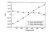
Hereinafter, the superiority of the calcination treatment by plasma heating will be described in more detail with reference to FIG.
In general, in order to reduce a stable metal oxide (eg, Nb 2 O 5 ) having low free energy of formation to metal, (1) Ca reduction, (2) molten salt electrolysis, (3) laser reduction, etc. A powerful reduction method is required. However, if such a powerful reduction method is used, the object to be reduced becomes very hot, and therefore, if it is applied to Nd magnet particles as in the present invention, the Nd magnet particles may be melted. .
Here, as described above, high-temperature hydrogen radicals can be generated by calcination by high-temperature hydrogen plasma heating. And in the reduction | restoration by a hydrogen radical, as shown in FIG. Therefore, metal oxides with low free energy of formation such as Nb 2 O 5 can be reduced at a lower temperature than the reduction methods (1) to (3). In addition, it can be judged from the fact that Nd magnet particles after calcination are not melted can be reduced at a low temperature.
また、上記プラズマ等による仮焼処理に加えて、水素雰囲気において200℃〜900℃、より好ましくは400℃〜900℃(例えば600℃)で数時間(例えば5時間)保持することによる仮焼処理(水素中仮焼処理)を更に行う構成としても良い。この水素中仮焼処理を行うタイミングは、上記プラズマ加熱による仮焼処理を行う前でも、行った後でも良い。更に、成形前の磁石粉末に対して行っても良いし、成形後の磁石粉末に対して行っても良い。この水素中仮焼処理では、有機金属化合物を熱分解させて、仮焼体中の炭素量を低減させる所謂脱カーボンが行われる。また、水素中仮焼処理は、仮焼体中の炭素量が0.15wt%以下、より好ましくは0.1wt%以下とする条件で行うこととする。それによって、その後の焼結処理で永久磁石1全体を緻密に焼結させることが可能となり、残留磁束密度や保磁力を低下させることが無い。また、水素中仮焼処理を行った場合には、水素中仮焼処理によって活性化された仮焼体の活性度を低下させる為に、仮焼処理後に仮焼体を真空雰囲気で200℃〜600℃、より好ましくは400℃〜600℃で1〜3時間保持することにより脱水素処理を行っても良い。但し、水素仮焼後に外気と触れさせることがなく焼成を行う場合には、脱水素工程は不要となる。
Further, in addition to the calcining treatment using plasma or the like, the calcining treatment is performed by holding at 200 ° C. to 900 ° C., more preferably 400 ° C. to 900 ° C. (eg 600 ° C.) for several hours (eg 5 hours) in a hydrogen atmosphere. It is good also as a structure which performs (calcination process in hydrogen) further. The timing for performing the calcination treatment in hydrogen may be before or after performing the calcination treatment by the plasma heating. Furthermore, it may be performed on the magnet powder before molding, or may be performed on the magnet powder after molding. In the calcination treatment in hydrogen, so-called decarbonization is performed in which the organometallic compound is thermally decomposed to reduce the amount of carbon in the calcined body. Further, the calcination treatment in hydrogen is performed under the condition that the carbon content in the calcined body is 0.15 wt% or less, more preferably 0.1 wt% or less. Accordingly, the entire
次に、プラズマ加熱による仮焼処理によって仮焼された粉末状の仮焼体65を成形装置50により所定形状に圧粉成形する。
Next, the powdery
図5に示すように、成形装置50は、円筒状のモールド51と、モールド51に対して上下方向に摺動する下パンチ52と、同じくモールド51に対して上下方向に摺動する上パンチ53とを有し、これらに囲まれた空間がキャビティ54を構成する。
また、成形装置50には一対の磁界発生コイル55、56がキャビティ54の上下位置に配置されており、磁力線をキャビティ54に充填された仮焼体65に印加する。印加させる磁場は例えば10kOeとする。
As shown in FIG. 5, the
In addition, a pair of magnetic field generating coils 55 and 56 are disposed in the
そして、圧粉成形を行う際には、先ず仮焼体65をキャビティ54に充填する。その後、下パンチ52及び上パンチ53を駆動し、キャビティ54に充填された仮焼体65に対して矢印61方向に圧力を加え、成形する。また、加圧と同時にキャビティ54に充填された仮焼体65に対して、加圧方向と平行な矢印62方向に磁界発生コイル55、56によってパルス磁場を印加する。それによって、所望の方向に磁場を配向させる。尚、磁場を配向させる方向は、仮焼体65から成形される永久磁石1に求められる磁場方向を考慮して決定する必要がある。
And when performing compacting, first, the
その後、成形された仮焼体65を焼結する焼結処理を行う。尚、成形体の焼結方法としては、一般的な真空焼結以外に成形体を加圧した状態で焼結する加圧焼結等も用いることが可能である。例えば、真空焼結で焼結を行う場合には、所定の昇温速度で800℃〜1080℃程度まで昇温し、2時間程度保持する。この間は真空焼成となるが真空度としては10−4Torr以下とすることが好ましい。その後冷却し、再び600℃〜1000℃で2時間熱処理を行う。そして、焼結の結果、永久磁石1が製造される。
Thereafter, a sintering process for sintering the formed calcined
一方、加圧焼結としては、例えば、ホットプレス焼結、熱間静水圧加圧(HIP)焼結、放電プラズマ(SPS)焼結等がある。但し、焼結時の磁石粒子の粒成長を抑制するとともに焼結後の磁石に生じる反りを抑える為に、一軸方向に加圧する一軸加圧焼結であって且つ通電焼結により焼結するSPS焼結を用いることが好ましい。尚、SPS焼結で焼結を行う場合には、加圧値を30MPaとし、数Pa以下の真空雰囲気で940℃まで10℃/分で上昇させ、その後5分保持することが好ましい。その後冷却し、再び600℃〜1000℃で2時間熱処理を行う。そして、焼結の結果、永久磁石1が製造される。
On the other hand, examples of pressure sintering include hot press sintering, hot isostatic pressing (HIP) sintering, and discharge plasma (SPS) sintering. However, in order to suppress the grain growth of the magnet particles during sintering and to suppress the warpage generated in the sintered magnet, the SPS is uniaxial pressure sintering that pressurizes in a uniaxial direction and is sintered by current sintering. Sintering is preferably used. In addition, when sintering by SPS sintering, it is preferable to make a pressurization value into 30 Mpa, to raise to 940 degreeC by 10 degree-C / min in a vacuum atmosphere of several Pa or less, and hold | maintain after that for 5 minutes. Then, it is cooled and heat-treated again at 600 to 1000 ° C. for 2 hours. And the
[永久磁石の製造方法2]
次に、本発明に係る永久磁石1の他の製造方法である第2の製造方法について図7を用いて説明する。図7は本発明に係る永久磁石1の第2の製造方法における製造工程を示した説明図である。
[Permanent magnet manufacturing method 2]
Next, the 2nd manufacturing method which is another manufacturing method of the
尚、スラリー42を生成するまでの工程は、図5を用いて既に説明した第1の製造方法における製造工程と同様であるので説明は省略する。
The steps until the
先ず、生成したスラリー42を成形前に真空乾燥などで事前に乾燥させ、乾燥した磁石粉末43を取り出す。その後、乾燥した磁石粉末を成形装置50により所定形状に圧粉成形する。尚、圧粉成形には、上記の乾燥した微粉末をキャビティに充填する乾式法と、溶媒などでスラリー状にしてからキャビティに充填する湿式法があるが、本発明では乾式法を用いる場合を例示する。また、有機金属化合物溶液は成形後の焼成段階で揮発させることも可能である。尚、成形装置50の詳細については図5を用いて既に説明した第1の製造方法における製造工程と同様であるので説明は省略する。また、湿式法を用いる場合には、キャビティ54に磁場を印加しながらスラリーを注入し、注入途中又は注入終了後に、当初の磁場より強い磁場を印加して湿式成形しても良い。また、加圧方向に対して印加方向が垂直となるように磁界発生コイル55、56を配置しても良い。
First, the produced
次に、圧粉成形により成形された成形体71に対して、高温水素プラズマを用いたプラズマ加熱による仮焼処理を行う。具体的には、成形体71をプラズマ加熱装置内に投入し、水素ガスと不活性ガス(例えばArガス)の混合ガスに電圧を印加することによりプラズマ励起し、発生された高温水素プラズマを成形体71に照射することにより仮焼処理を行う。尚、供給するガスの流量は水素流量1L/min〜10L/min、アルゴン流量1L/min〜5L/minとし、プラズマ励起する際の出力電力を1kW〜10kWとし、プラズマの照射時間は1秒〜60秒で行う。
Next, the calcination process by the plasma heating using high temperature hydrogen plasma is performed with respect to the molded
その後、プラズマ加熱により仮焼された成形体71を焼結する焼結処理を行う。尚、焼結処理は、上述した第1の製造方法と同様に、真空焼結や加圧焼結等により行う。焼結条件の詳細については既に説明した第1の製造方法における製造工程と同様であるので説明は省略する。そして、焼結の結果、永久磁石1が製造される。
Then, the sintering process which sinters the molded
尚、上述した第1の製造方法では、粉末状の磁石粒子に対して仮焼処理を行うので、成形後の磁石粒子に対して仮焼処理を行う前記第2の製造方法と比較して、金属酸化物の還元を磁石粒子全体に対してより容易に行うことができる利点がある。即ち、前記第2の製造方法と比較して仮焼体中の酸素量をより確実に低減させることが可能となる。 In the first manufacturing method described above, since the calcined treatment is performed on the powdered magnet particles, compared with the second manufacturing method in which the calcined processing is performed on the magnet particles after molding, There exists an advantage which can reduce | restore metal oxide more easily with respect to the whole magnet particle. That is, it becomes possible to more reliably reduce the amount of oxygen in the calcined body as compared with the second manufacturing method.
以下に、本発明の実施例について比較例と比較しつつ説明する。
(実施例)
実施例のネオジム磁石粉末の合金組成は、化学量論組成に基づく分率(Nd:26.7wt%、Fe(電解鉄):72.3wt%、B:1.0wt%)よりもNdの比率を高くし、例えばwt%でNd/Fe/B=32.7/65.96/1.34とする。また、粉砕したネオジム磁石粉末に有機金属化合物としてニオブn−プロポキシドを5wt%添加した。また、プラズマ加熱による仮焼処理は、高温水素プラズマを用い、ガスの流量を水素流量3L/min、アルゴン流量3L/minとし、プラズマ励起する際の出力電力を3kWとし、プラズマの照射時間は60秒で行った。また、成形された仮焼体の焼結はSPS焼結により行った。尚、他の工程は上述した[永久磁石の製造方法1]と同様の工程とする。
Examples of the present invention will be described below in comparison with comparative examples.
(Example)
The alloy composition of the neodymium magnet powder of the example is a ratio of Nd rather than a fraction based on the stoichiometric composition (Nd: 26.7 wt%, Fe (electrolytic iron): 72.3 wt%, B: 1.0 wt%). For example, Nd / Fe / B = 32.7 / 65.96 / 1.34 at wt%. Further, 5 wt% of niobium n-propoxide as an organometallic compound was added to the pulverized neodymium magnet powder. The calcining treatment by plasma heating uses high-temperature hydrogen plasma, the gas flow rate is 3 L / min hydrogen, the argon flow rate is 3 L / min, the output power at the time of plasma excitation is 3 kW, and the plasma irradiation time is 60 Went in seconds. Further, the sintered calcined body was sintered by SPS sintering. The other steps are the same as those in [Permanent magnet manufacturing method 1] described above.
(比較例)
添加する有機金属化合物をニオブn−プロポキシドとし、プラズマ加熱による仮焼処理を行わずに焼結した。他の条件は実施例と同様である。
(Comparative example)
The organometallic compound to be added was niobium n-propoxide, which was sintered without performing a calcination treatment by plasma heating. Other conditions are the same as in the example.
(プラズマ加熱による仮焼処理の有無に基づく実施例と比較例との比較検討)
実施例と比較例の永久磁石についてそれぞれX線光電子分光装置(ECSA)による分析を行った。図8は、実施例と比較例の永久磁石について、200eV〜215eVの結合エネルギの範囲で検出されたスペクトルを示した図である。また、図9は、図8に示すスペクトルの波形解析の結果について示した図である。
(Comparison study between examples and comparative examples based on the presence or absence of calcination treatment by plasma heating)
The permanent magnets of the examples and comparative examples were each analyzed by an X-ray photoelectron spectrometer (ECSA). FIG. 8 is a diagram showing spectra detected in the range of the binding energy of 200 eV to 215 eV for the permanent magnets of the example and the comparative example. FIG. 9 is a diagram showing the results of the waveform analysis of the spectrum shown in FIG.
図8に示すように、実施例の永久磁石と比較例の永久磁石はそれぞれ異なるスペクトル形状を有する。ここで、各スペクトルについて、標準試料のスペクトルに基づきスペクトルの混合割合を算出し、Nb、NbO、Nb2O3、NbO2、Nb2O5の割合を算出すると、図9に示す結果となる。図9に示すように、実施例の永久磁石では、Nbの割合が81%であり、Nb酸化物であるNbOの割合が19%となる。一方、比較例の永久磁石では、Nbの割合がほぼ0%であり、Nb酸化物であるNb2O5の割合がほぼ100%となる。 As shown in FIG. 8, the permanent magnet of the example and the permanent magnet of the comparative example have different spectral shapes. Here, for each spectrum, the mixing ratio of the spectrum is calculated based on the spectrum of the standard sample, and the ratio of Nb, NbO, Nb 2 O 3 , NbO 2 , Nb 2 O 5 is calculated, and the result shown in FIG. 9 is obtained. . As shown in FIG. 9, in the permanent magnet of the example, the ratio of Nb is 81%, and the ratio of NbO that is Nb oxide is 19%. On the other hand, in the permanent magnet of the comparative example, the ratio of Nb is approximately 0%, and the ratio of Nb 2 O 5 that is an Nb oxide is approximately 100%.
即ち、プラズマ加熱による仮焼処理を行った実施例の永久磁石では、酸素と結びついた状態で存在するNb酸化物(NbO、Nb2O3、NbO2、Nb2O5)の大部分を、金属Nbへと還元することができていることが分かる。また、金属Nbまで還元できなかった場合でも、NbO等のより酸化数の少ない酸化物への還元(即ち酸化数の低減)を行うことができ、磁石粉末に含有する酸素を予め低減させることができる。その結果、実施例の永久磁石では、焼結を行う前に磁石粉末に含有するNb酸化物等について還元されることにより、磁石粉末に含有する酸素を予め低減させることができる。それにより、その後の焼結工程でNdと酸素が結合しNd酸化物を形成することがない。従って、実施例の永久磁石では、金属酸化物によって磁石特性が低下することなく、αFeの析出についても防止することができる。即ち、高い品質を有する永久磁石を実現することが可能となる。
一方で、比較例の永久磁石は、Nb酸化物が多く残存することから、焼結工程においてNdと酸素が結合しNd酸化物を形成することとなる。また、αFeが多数析出することとなる。その結果、磁気特性が低下する。
That is, in the permanent magnet of the example that was subjected to the calcining treatment by plasma heating, most of the Nb oxides (NbO, Nb 2 O 3 , NbO 2 , Nb 2 O 5 ) existing in a state of being combined with oxygen, It turns out that it can reduce | restore to metal Nb. Further, even when metal Nb cannot be reduced, reduction to an oxide having a lower oxidation number such as NbO (that is, reduction of the oxidation number) can be performed, and oxygen contained in the magnet powder can be reduced in advance. it can. As a result, in the permanent magnet of the example, oxygen contained in the magnet powder can be reduced in advance by reducing the Nb oxide and the like contained in the magnet powder before sintering. As a result, Nd and oxygen are not combined in the subsequent sintering step to form an Nd oxide. Therefore, in the permanent magnet of the example, the precipitation of αFe can be prevented without deteriorating the magnet characteristics due to the metal oxide. That is, it becomes possible to realize a permanent magnet having high quality.
On the other hand, since a large amount of Nb oxide remains in the permanent magnet of the comparative example, Nd and oxygen are combined in the sintering process to form an Nd oxide. In addition, a lot of αFe is precipitated. As a result, the magnetic characteristics are degraded.
以上説明したように、本実施形態に係る永久磁石1及び永久磁石1の製造方法では、ネオジム磁石の微粉末に対して、M−(OR)x(式中、MはV、Mo、Zr、Ta、Ti、W又はNbである。Rは炭化水素からなる置換基であり、直鎖でも分枝でも良い。xは任意の整数である。)で示される有機金属化合物が添加された有機金属化合物溶液を加え、ネオジム磁石の粒子表面に対して均一に有機金属化合物を付着させる。その後、磁石粉末をプラズマ加熱による仮焼処理を行う。その後、成形した後に真空焼結や加圧焼結を行うことによって永久磁石1を製造する。それにより、従来に比べてNb等の添加する量を少量としたとしても、添加されたNb等を磁石の粒界に効率よく偏在させることができる。その結果、焼結時の磁石粒子の粒成長を抑制することができるとともに、焼結後における結晶粒子間での交換相互作用を分断することによって各結晶粒子の磁化反転を妨げ、磁気性能を向上させることが可能となる。また、他の有機金属化合物を添加する場合と比較して脱カーボンを容易に行うことが可能であり、焼結後の磁石内に含まれる炭素によって保磁力が低下する虞が無く、また、磁石全体を緻密に焼結することが可能となる。
更に、高融点金属であるNb等が焼結後に磁石の粒界に偏在するので、粒界に偏在されたNb等が焼結時の磁石粒子の粒成長を抑制するとともに、焼結後は結晶粒子間での交換相互作用を分断することによって各結晶粒子の磁化反転を妨げ、磁気性能を向上させることが可能となる。また、Nb等の添加量が従来に比べて少ないので、残留磁束密度の低下を抑制することができる。
また、磁石の粒界に偏在されたNb等は、焼結後に磁石の粒子表面に1nm〜200nm、好ましくは2nm〜50nmの厚さの層を形成するので、焼結時の磁石粒子の粒成長を抑制するとともに、焼結後における結晶粒子間での交換相互作用を分断することによって各結晶粒子の磁化反転を妨げ、磁気性能を向上させることが可能となる。
また、磁石原料を単磁区粒子径の磁石粉末を含む磁石粉末へ粉砕することとすれば、焼結時の単磁区粒子径を有する磁石粒子の粒成長を抑制することができる。また、粒成長が抑制されることにより、焼結後の永久磁石の結晶粒を単磁区とすることが可能となる。その結果、永久磁石1の磁気性能を飛躍的に向上させることが可能となる。
また、有機金属化合物が添加された磁石粉末や成形体を焼結前にプラズマ加熱によって仮焼することにより、仮焼前に酸素と結びついた状態で存在するNb等を、金属Nb等へと還元することや、NbO等のより酸化数の少ない酸化物への還元(即ち酸化数の低減)を行うことができる。従って、有機金属化合物が添加された場合であっても、磁石粒子の含有する酸素量が増加することを防止することができる。従って、焼結後の磁石の主相内にαFeが析出することや酸化物の生成を抑え、磁石特性を大きく低下させることがない。
また、プラズマ加熱による仮焼処理では、出力電力1kW〜10kW、水素流量1L/min〜10L/min、アルゴン流量1L/min〜5L/min、照射時間1秒〜60秒で行うので、高温水素プラズマ加熱を用いて適切な条件により磁石粉末又は成形体の仮焼を行うことによって、磁石粒子の含有する酸素量をより確実に低減させることができる。更に、高温水素プラズマ加熱を用いて仮焼するので、高い濃度の水素ラジカルを生成することができ、有機金属化合物を形成する金属が安定な酸化物として磁石粉末中に存在する場合であっても、水素ラジカルを用いて金属への還元や酸化数低減を低温で容易に行うことが可能となる。
また、特に第1の製造方法では、粉末状の磁石粒子に対して仮焼を行うので、成形後の磁石粒子に対して仮焼を行う場合と比較して、金属酸化物の還元を磁石粒子全体に対してより容易に行うことができる利点がある。即ち、前記第2の製造方法と比較して仮焼体中の酸素量をより確実に低減させることが可能となる。
また、特に添加する有機金属化合物としてアルキル基から構成される有機金属化合物、より好ましくは炭素数2〜6のアルキル基から構成される有機金属化合物を用いれば、水素雰囲気で磁石粉末や成形体を仮焼する際に、低温で有機金属化合物の熱分解を行うことが可能となる。それによって、有機金属化合物の熱分解を磁石粉末全体や成形体全体に対してより容易に行うことができる。その結果、焼結後の磁石の主相内にαFeが析出することを抑え、磁石全体を緻密に焼結することが可能となり、保磁力が低下することを防止できる。
As described above, in the
Further, Nb or the like, which is a high melting point metal, is unevenly distributed at the grain boundaries of the magnet after sintering. By breaking the exchange interaction between particles, it is possible to prevent the magnetization reversal of each crystal particle and improve the magnetic performance. Moreover, since the addition amount of Nb etc. is small compared with the past, the fall of a residual magnetic flux density can be suppressed.
Further, Nb and the like that are unevenly distributed at the grain boundaries of the magnet form a layer having a thickness of 1 nm to 200 nm, preferably 2 nm to 50 nm, on the surface of the magnet particles after sintering. It is possible to prevent the magnetization reversal of each crystal particle and to improve the magnetic performance by suppressing the exchange interaction between the crystal particles after sintering.
Further, if the magnet raw material is pulverized into magnet powder containing magnet powder having a single domain particle diameter, grain growth of magnet particles having a single domain particle diameter during sintering can be suppressed. Further, by suppressing the grain growth, the sintered permanent magnet crystal grains can be made into a single magnetic domain. As a result, the magnetic performance of the
In addition, by magnetizing a magnet powder or molded body to which an organometallic compound has been added by plasma heating before sintering, Nb or the like existing in a state associated with oxygen before calcination is reduced to metal Nb or the like. Or reduction to an oxide having a lower oxidation number such as NbO (that is, reduction of the oxidation number). Therefore, even when an organometallic compound is added, it is possible to prevent an increase in the amount of oxygen contained in the magnet particles. Accordingly, the precipitation of αFe in the main phase of the magnet after sintering and the generation of oxides are suppressed, and the magnet characteristics are not greatly deteriorated.
In addition, the calcination treatment by plasma heating is performed at an output power of 1 kW to 10 kW, a hydrogen flow rate of 1 L / min to 10 L / min, an argon flow rate of 1 L / min to 5 L / min, and an irradiation time of 1 second to 60 seconds. By calcining the magnet powder or the molded body under appropriate conditions using heating, the amount of oxygen contained in the magnet particles can be more reliably reduced. Furthermore, since calcining is performed using high-temperature hydrogen plasma heating, high-concentration hydrogen radicals can be generated, and even when the metal forming the organometallic compound is present as a stable oxide in the magnet powder. Further, reduction to a metal and reduction of the oxidation number using hydrogen radicals can be easily performed at a low temperature.
In particular, in the first manufacturing method, since the powdered magnet particles are calcined, the reduction of the metal oxide is reduced compared to the case of calcining the molded magnet particles. There is an advantage that it can be easily performed on the whole. That is, it becomes possible to more reliably reduce the amount of oxygen in the calcined body as compared with the second manufacturing method.
In particular, if an organometallic compound composed of an alkyl group, more preferably an organometallic compound composed of an alkyl group having 2 to 6 carbon atoms, is used as the organometallic compound to be added, the magnet powder or molded body can be produced in a hydrogen atmosphere. When calcination, it is possible to thermally decompose the organometallic compound at a low temperature. Thereby, the thermal decomposition of the organometallic compound can be more easily performed on the entire magnet powder or the entire compact. As a result, it is possible to suppress the precipitation of αFe in the main phase of the magnet after sintering, to densely sinter the entire magnet, and to prevent the coercive force from being lowered.
尚、本発明は前記実施例に限定されるものではなく、本発明の要旨を逸脱しない範囲内で種々の改良、変形が可能であることは勿論である。
また、磁石粉末の粉砕条件、混練条件、仮焼条件、脱水素条件、焼結条件などは上記実施例に記載した条件に限られるものではない。
In addition, this invention is not limited to the said Example, Of course, various improvement and deformation | transformation are possible within the range which does not deviate from the summary of this invention.
Moreover, the pulverization conditions, kneading conditions, calcination conditions, dehydrogenation conditions, sintering conditions, etc. of the magnet powder are not limited to the conditions described in the above examples.
また、上記実施例では磁石粉末に添加するNb等を含む有機金属化合物としてニオブn−プロポキシドを用いているが、M−(OR)x(式中、MはV、Mo、Zr、Ta、Ti、W又はNbである。Rは炭化水素からなる置換基であり、直鎖でも分枝でも良い。xは任意の整数である。)で示される有機金属化合物であれば、他の有機金属化合物であっても良い。例えば、炭素数が7以上のアルキル基から構成される有機金属化合物や、アルキル基以外の炭化水素からなる置換基から構成される有機金属化合物を用いても良い。 Moreover, in the said Example, although niobium n-propoxide is used as an organometallic compound containing Nb etc. which are added to magnet powder, M- (OR) x (In the formula, M is V, Mo, Zr, Ta, Ti, W, or Nb, R is a hydrocarbon substituent, which may be linear or branched, and x is an arbitrary integer. It may be a compound. For example, an organometallic compound composed of an alkyl group having 7 or more carbon atoms or an organometallic compound composed of a substituent composed of a hydrocarbon other than an alkyl group may be used.
1 永久磁石
10 Nd結晶粒子
11 高融点金属層
12 高融点金属粒
42 スラリー
43 磁石粉末
65 仮焼体
71 成形体
DESCRIPTION OF
Claims (14)
前記粉砕された磁石粉末に以下の構造式
M−(OR)x
(式中、MはV、Mo、Zr、Ta、Ti、W又はNbである。Rは炭化水素からなる置換基であり、直鎖でも分枝でも良い。xは任意の整数である。)
で表わされる有機金属化合物を添加することにより、前記磁石粉末の粒子表面に前記有機金属化合物を付着させる工程と、
前記有機金属化合物が粒子表面に付着された前記磁石粉末をプラズマ加熱により仮焼して仮焼体を得る工程と、
前記仮焼体を成形することにより成形体を形成する工程と、
前記成形体を焼結する工程と、
により製造されることを特徴とする永久磁石。 Crushing magnet raw material into magnet powder;
The pulverized magnet powder has the following structural formula M- (OR) x
(In the formula, M is V, Mo, Zr, Ta, Ti, W, or Nb. R is a substituent composed of hydrocarbon, which may be linear or branched. X is an arbitrary integer.)
A step of attaching the organometallic compound to the particle surface of the magnet powder by adding an organometallic compound represented by:
A step of calcining the magnet powder with the organometallic compound attached to the particle surface by plasma heating to obtain a calcined body;
Forming the molded body by molding the calcined body,
Sintering the molded body;
A permanent magnet manufactured by the method described above.
前記粉砕された磁石粉末に以下の構造式
M−(OR)x
(式中、MはV、Mo、Zr、Ta、Ti、W又はNbである。Rは炭化水素からなる置換基であり、直鎖でも分枝でも良い。xは任意の整数である。)
で表わされる有機金属化合物を添加することにより、前記磁石粉末の粒子表面に前記有機金属化合物を付着させる工程と、
前記有機金属化合物が粒子表面に付着された前記磁石粉末を成形することにより成形体を形成する工程と、
前記成形体をプラズマ加熱により仮焼して仮焼体を得る工程と、
前記仮焼体を焼結する工程と、
により製造されることを特徴とする永久磁石。 Crushing magnet raw material into magnet powder;
The pulverized magnet powder has the following structural formula M- (OR) x
(In the formula, M is V, Mo, Zr, Ta, Ti, W, or Nb. R is a substituent composed of hydrocarbon, which may be linear or branched. X is an arbitrary integer.)
A step of attaching the organometallic compound to the particle surface of the magnet powder by adding an organometallic compound represented by:
Forming the molded body by molding the magnet powder having the organometallic compound attached to the particle surface;
Calcination of the molded body by plasma heating to obtain a calcined body;
Sintering the calcined body;
A permanent magnet manufactured by the method described above.
前記粉砕された磁石粉末に以下の構造式
M−(OR)x
(式中、MはV、Mo、Zr、Ta、Ti、W又はNbである。Rは炭化水素からなる置換基であり、直鎖でも分枝でも良い。xは任意の整数である。)
で表わされる有機金属化合物を添加することにより、前記磁石粉末の粒子表面に前記有機金属化合物を付着させる工程と、
前記有機金属化合物が粒子表面に付着された前記磁石粉末をプラズマ加熱により仮焼して仮焼体を得る工程と、
前記仮焼体を成形することにより成形体を形成する工程と、
前記成形体を焼結する工程と、
を有することを特徴とする永久磁石の製造方法。 Crushing magnet raw material into magnet powder;
The pulverized magnet powder has the following structural formula M- (OR) x
(In the formula, M is V, Mo, Zr, Ta, Ti, W, or Nb. R is a substituent composed of hydrocarbon, which may be linear or branched. X is an arbitrary integer.)
A step of attaching the organometallic compound to the particle surface of the magnet powder by adding an organometallic compound represented by:
A step of calcining the magnet powder with the organometallic compound attached to the particle surface by plasma heating to obtain a calcined body;
Forming the molded body by molding the calcined body,
Sintering the molded body;
The manufacturing method of the permanent magnet characterized by having.
前記粉砕された磁石粉末に以下の構造式
M−(OR)x
(式中、MはV、Mo、Zr、Ta、Ti、W又はNbである。Rは炭化水素からなる置換基であり、直鎖でも分枝でも良い。xは任意の整数である。)
で表わされる有機金属化合物を添加することにより、前記磁石粉末の粒子表面に前記有機金属化合物を付着させる工程と、
前記有機金属化合物が粒子表面に付着された前記磁石粉末を成形することにより成形体を形成する工程と、
前記成形体をプラズマ加熱により仮焼して仮焼体を得る工程と、
前記仮焼体を焼結する工程と、
を有することを特徴とする永久磁石の製造方法。 Crushing magnet raw material into magnet powder;
The pulverized magnet powder has the following structural formula M- (OR) x
(In the formula, M is V, Mo, Zr, Ta, Ti, W, or Nb. R is a substituent composed of hydrocarbon, which may be linear or branched. X is an arbitrary integer.)
A step of attaching the organometallic compound to the particle surface of the magnet powder by adding an organometallic compound represented by:
Forming the molded body by molding the magnet powder having the organometallic compound attached to the particle surface;
Calcination of the molded body by plasma heating to obtain a calcined body;
Sintering the calcined body;
The manufacturing method of the permanent magnet characterized by having.
Priority Applications (1)
| Application Number | Priority Date | Filing Date | Title |
|---|---|---|---|
| JP2011069074A JP4865920B2 (en) | 2010-03-31 | 2011-03-28 | Permanent magnet and method for manufacturing permanent magnet |
Applications Claiming Priority (3)
| Application Number | Priority Date | Filing Date | Title |
|---|---|---|---|
| JP2010084457 | 2010-03-31 | ||
| JP2010084457 | 2010-03-31 | ||
| JP2011069074A JP4865920B2 (en) | 2010-03-31 | 2011-03-28 | Permanent magnet and method for manufacturing permanent magnet |
Publications (2)
| Publication Number | Publication Date |
|---|---|
| JP2011228666A JP2011228666A (en) | 2011-11-10 |
| JP4865920B2 true JP4865920B2 (en) | 2012-02-01 |
Family
ID=44762544
Family Applications (1)
| Application Number | Title | Priority Date | Filing Date |
|---|---|---|---|
| JP2011069074A Expired - Fee Related JP4865920B2 (en) | 2010-03-31 | 2011-03-28 | Permanent magnet and method for manufacturing permanent magnet |
Country Status (7)
| Country | Link |
|---|---|
| US (1) | US20120182109A1 (en) |
| EP (1) | EP2503573B1 (en) |
| JP (1) | JP4865920B2 (en) |
| KR (1) | KR101189840B1 (en) |
| CN (1) | CN102576603B (en) |
| TW (1) | TW201212067A (en) |
| WO (1) | WO2011125595A1 (en) |
Families Citing this family (12)
| Publication number | Priority date | Publication date | Assignee | Title |
|---|---|---|---|---|
| KR20120049349A (en) * | 2010-03-31 | 2012-05-16 | 닛토덴코 가부시키가이샤 | Permanent magnet and manufacturing method for permanent magnet |
| CN102511068A (en) * | 2010-03-31 | 2012-06-20 | 日东电工株式会社 | Permanent magnet and manufacturing method for permanent magnet |
| KR101189856B1 (en) * | 2010-03-31 | 2012-10-10 | 닛토덴코 가부시키가이샤 | Permanent magnet and manufacturing method for permanent magnet |
| JP5011420B2 (en) * | 2010-05-14 | 2012-08-29 | 日東電工株式会社 | Permanent magnet and method for manufacturing permanent magnet |
| JP5411957B2 (en) * | 2012-03-12 | 2014-02-12 | 日東電工株式会社 | Rare earth permanent magnet and method for producing rare earth permanent magnet |
| US20140197911A1 (en) * | 2012-03-12 | 2014-07-17 | Nitto Denko Corporation | Rare-earth permanent magnet and method for manufacturing rare-earth permanent magnet |
| KR20170003707A (en) * | 2012-03-12 | 2017-01-09 | 닛토덴코 가부시키가이샤 | Method for producing rare earth permanent magnet |
| DE102012214729A1 (en) * | 2012-08-20 | 2014-02-20 | Siemens Aktiengesellschaft | Process for the production of magnetic materials |
| CN105014074A (en) * | 2015-07-10 | 2015-11-04 | 北京科技大学 | Magnetizing type magnetic material 3D cold printing device |
| CN106111996B (en) * | 2016-08-19 | 2018-04-03 | 佛山市顺德区均安镇丰华磁铁实业有限公司 | Full-automatic magnet production system |
| KR102093491B1 (en) * | 2017-11-28 | 2020-03-25 | 주식회사 엘지화학 | Manufacturing method of sintered magnet and sintered magnet |
| CN112687443A (en) * | 2020-12-22 | 2021-04-20 | 苑红新 | Method for manufacturing neodymium iron boron magnet |
Family Cites Families (23)
| Publication number | Priority date | Publication date | Assignee | Title |
|---|---|---|---|---|
| CN1004637B (en) * | 1987-08-05 | 1989-06-28 | 北京有色金属研究总院 | Method for producing low-oxygen chromium powder |
| US5409543A (en) * | 1992-12-22 | 1995-04-25 | Sandia Corporation | Dry soldering with hot filament produced atomic hydrogen |
| JP3298219B2 (en) | 1993-03-17 | 2002-07-02 | 日立金属株式会社 | Rare earth-Fe-Co-Al-V-Ga-B based sintered magnet |
| US5641363A (en) * | 1993-12-27 | 1997-06-24 | Tdk Corporation | Sintered magnet and method for making |
| JP2001020065A (en) * | 1999-07-07 | 2001-01-23 | Hitachi Metals Ltd | Target for sputtering, its production and high melting point metal powder material |
| KR100562681B1 (en) * | 2000-05-24 | 2006-03-23 | 가부시키가이샤 네오맥스 | Permanent magnet including multiple ferromagnetic phases and method for producing the magnet |
| JP2004250781A (en) | 2002-10-08 | 2004-09-09 | Neomax Co Ltd | Sintered type permanent magnet, and production method therefor |
| JP2004281873A (en) * | 2003-03-18 | 2004-10-07 | Hitachi Metals Ltd | Method for manufacturing rare earth magnet |
| US7199690B2 (en) * | 2003-03-27 | 2007-04-03 | Tdk Corporation | R-T-B system rare earth permanent magnet |
| JP4374962B2 (en) * | 2003-03-28 | 2009-12-02 | 日産自動車株式会社 | Rare earth magnet and manufacturing method thereof, and motor using rare earth magnet |
| JP2005039089A (en) * | 2003-07-16 | 2005-02-10 | Neomax Co Ltd | Method for manufacturing nano crystal magnet using particulates |
| JP2005097697A (en) * | 2003-09-26 | 2005-04-14 | Toshiba Corp | Sputtering target and method for manufacturing the same |
| JP4525072B2 (en) * | 2003-12-22 | 2010-08-18 | 日産自動車株式会社 | Rare earth magnet and manufacturing method thereof |
| JP2005197299A (en) * | 2003-12-26 | 2005-07-21 | Tdk Corp | Rare earth sintered magnet and manufacturing method thereof |
| CN101031984B (en) * | 2005-07-15 | 2011-12-21 | 日立金属株式会社 | Rare earth sintered magnet and method for production thereof |
| US7276796B1 (en) * | 2006-03-15 | 2007-10-02 | International Business Machines Corporation | Formation of oxidation-resistant seed layer for interconnect applications |
| JP5266523B2 (en) * | 2008-04-15 | 2013-08-21 | 日東電工株式会社 | Permanent magnet and method for manufacturing permanent magnet |
| JP5057111B2 (en) * | 2009-07-01 | 2012-10-24 | 信越化学工業株式会社 | Rare earth magnet manufacturing method |
| CN102549684A (en) * | 2010-03-31 | 2012-07-04 | 日东电工株式会社 | Permanent magnet and manufacturing method for permanent magnet |
| KR101189856B1 (en) * | 2010-03-31 | 2012-10-10 | 닛토덴코 가부시키가이샤 | Permanent magnet and manufacturing method for permanent magnet |
| CN102511068A (en) * | 2010-03-31 | 2012-06-20 | 日东电工株式会社 | Permanent magnet and manufacturing method for permanent magnet |
| US9039920B2 (en) * | 2010-03-31 | 2015-05-26 | Nitto Denko Corporation | Permanent magnet and manufacturing method thereof |
| KR20120049349A (en) * | 2010-03-31 | 2012-05-16 | 닛토덴코 가부시키가이샤 | Permanent magnet and manufacturing method for permanent magnet |
-
2011
- 2011-03-28 EP EP11765495.4A patent/EP2503573B1/en not_active Not-in-force
- 2011-03-28 JP JP2011069074A patent/JP4865920B2/en not_active Expired - Fee Related
- 2011-03-28 CN CN201180003974.XA patent/CN102576603B/en not_active Expired - Fee Related
- 2011-03-28 KR KR1020127007181A patent/KR101189840B1/en not_active IP Right Cessation
- 2011-03-28 WO PCT/JP2011/057576 patent/WO2011125595A1/en active Application Filing
- 2011-03-28 US US13/499,571 patent/US20120182109A1/en not_active Abandoned
- 2011-03-31 TW TW100111412A patent/TW201212067A/en not_active IP Right Cessation
Also Published As
| Publication number | Publication date |
|---|---|
| EP2503573A4 (en) | 2013-01-23 |
| EP2503573B1 (en) | 2014-06-11 |
| WO2011125595A1 (en) | 2011-10-13 |
| CN102576603B (en) | 2014-04-16 |
| TW201212067A (en) | 2012-03-16 |
| KR101189840B1 (en) | 2012-10-10 |
| JP2011228666A (en) | 2011-11-10 |
| US20120182109A1 (en) | 2012-07-19 |
| KR20120049354A (en) | 2012-05-16 |
| EP2503573A1 (en) | 2012-09-26 |
| CN102576603A (en) | 2012-07-11 |
| TWI371049B (en) | 2012-08-21 |
Similar Documents
| Publication | Publication Date | Title |
|---|---|---|
| JP4865920B2 (en) | Permanent magnet and method for manufacturing permanent magnet | |
| JP4865100B2 (en) | Permanent magnet and method for manufacturing permanent magnet | |
| JP4865919B2 (en) | Permanent magnet and method for manufacturing permanent magnet | |
| JP4923148B2 (en) | Permanent magnet and method for manufacturing permanent magnet | |
| JP4865098B2 (en) | Permanent magnet and method for manufacturing permanent magnet | |
| JP4923153B2 (en) | Permanent magnet and method for manufacturing permanent magnet | |
| JP4923151B2 (en) | Permanent magnet and method for manufacturing permanent magnet | |
| JP4923147B2 (en) | Permanent magnet and method for manufacturing permanent magnet | |
| JP4865097B2 (en) | Permanent magnet and method for manufacturing permanent magnet | |
| JP4865099B2 (en) | Permanent magnet and method for manufacturing permanent magnet | |
| JP4923149B2 (en) | Permanent magnet and method for manufacturing permanent magnet | |
| JP5908247B2 (en) | Method for manufacturing permanent magnet | |
| JP4923150B2 (en) | Permanent magnet and method for manufacturing permanent magnet | |
| JP2011216720A (en) | Permanent magnet and method for manufacturing the same | |
| JP5453154B2 (en) | Permanent magnet and method for manufacturing permanent magnet | |
| JP2011216705A (en) | Permanent magnet and method for manufacturing the same | |
| JP2011216732A (en) | Permanent magnet and method for manufacturing the same | |
| JP2011216724A (en) | Permanent magnet and method for manufacturing the same |
Legal Events
| Date | Code | Title | Description |
|---|---|---|---|
| A871 | Explanation of circumstances concerning accelerated examination |
Free format text: JAPANESE INTERMEDIATE CODE: A871 Effective date: 20110927 |
|
| A975 | Report on accelerated examination |
Free format text: JAPANESE INTERMEDIATE CODE: A971005 Effective date: 20111003 |
|
| TRDD | Decision of grant or rejection written | ||
| A01 | Written decision to grant a patent or to grant a registration (utility model) |
Free format text: JAPANESE INTERMEDIATE CODE: A01 Effective date: 20111108 |
|
| A01 | Written decision to grant a patent or to grant a registration (utility model) |
Free format text: JAPANESE INTERMEDIATE CODE: A01 |
|
| A61 | First payment of annual fees (during grant procedure) |
Free format text: JAPANESE INTERMEDIATE CODE: A61 Effective date: 20111110 |
|
| FPAY | Renewal fee payment (event date is renewal date of database) |
Free format text: PAYMENT UNTIL: 20141118 Year of fee payment: 3 |
|
| R150 | Certificate of patent or registration of utility model |
Free format text: JAPANESE INTERMEDIATE CODE: R150 |
|
| R250 | Receipt of annual fees |
Free format text: JAPANESE INTERMEDIATE CODE: R250 |
|
| R250 | Receipt of annual fees |
Free format text: JAPANESE INTERMEDIATE CODE: R250 |
|
| R250 | Receipt of annual fees |
Free format text: JAPANESE INTERMEDIATE CODE: R250 |
|
| R250 | Receipt of annual fees |
Free format text: JAPANESE INTERMEDIATE CODE: R250 |
|
| LAPS | Cancellation because of no payment of annual fees |