JP4864632B2 - Image input device, image input method, personal authentication device, and electronic device - Google Patents
Image input device, image input method, personal authentication device, and electronic device Download PDFInfo
- Publication number
- JP4864632B2 JP4864632B2 JP2006278423A JP2006278423A JP4864632B2 JP 4864632 B2 JP4864632 B2 JP 4864632B2 JP 2006278423 A JP2006278423 A JP 2006278423A JP 2006278423 A JP2006278423 A JP 2006278423A JP 4864632 B2 JP4864632 B2 JP 4864632B2
- Authority
- JP
- Japan
- Prior art keywords
- image
- subject
- living body
- lens
- eye image
- Prior art date
- Legal status (The legal status is an assumption and is not a legal conclusion. Google has not performed a legal analysis and makes no representation as to the accuracy of the status listed.)
- Expired - Fee Related
Links
- 238000000034 method Methods 0.000 title claims description 62
- 238000012545 processing Methods 0.000 claims description 148
- 230000003287 optical effect Effects 0.000 claims description 128
- 150000001875 compounds Chemical class 0.000 claims description 112
- 238000012937 correction Methods 0.000 claims description 107
- 238000012546 transfer Methods 0.000 claims description 79
- 238000003384 imaging method Methods 0.000 claims description 49
- 230000008569 process Effects 0.000 claims description 34
- 230000008859 change Effects 0.000 claims description 31
- 230000015556 catabolic process Effects 0.000 claims description 19
- 238000006731 degradation reaction Methods 0.000 claims description 19
- 230000001678 irradiating effect Effects 0.000 claims description 19
- 230000006866 deterioration Effects 0.000 claims description 17
- 238000001514 detection method Methods 0.000 claims description 12
- 230000006870 function Effects 0.000 description 53
- 210000003462 vein Anatomy 0.000 description 43
- 238000004364 calculation method Methods 0.000 description 35
- 238000007781 pre-processing Methods 0.000 description 13
- 238000012805 post-processing Methods 0.000 description 11
- 238000010586 diagram Methods 0.000 description 8
- 230000007423 decrease Effects 0.000 description 6
- 238000005286 illumination Methods 0.000 description 5
- 210000000158 ommatidium Anatomy 0.000 description 5
- 210000003491 skin Anatomy 0.000 description 5
- 230000008901 benefit Effects 0.000 description 4
- 230000000694 effects Effects 0.000 description 4
- 238000012986 modification Methods 0.000 description 4
- 230000004048 modification Effects 0.000 description 4
- 238000005070 sampling Methods 0.000 description 4
- 238000013459 approach Methods 0.000 description 3
- 230000002500 effect on skin Effects 0.000 description 3
- 239000000463 material Substances 0.000 description 3
- 238000003672 processing method Methods 0.000 description 3
- 230000000007 visual effect Effects 0.000 description 3
- 238000013461 design Methods 0.000 description 2
- 239000000284 extract Substances 0.000 description 2
- 239000011521 glass Substances 0.000 description 2
- 238000001727 in vivo Methods 0.000 description 2
- 238000009434 installation Methods 0.000 description 2
- 239000011347 resin Substances 0.000 description 2
- 229920005989 resin Polymers 0.000 description 2
- 238000004088 simulation Methods 0.000 description 2
- 238000012935 Averaging Methods 0.000 description 1
- WQZGKKKJIJFFOK-GASJEMHNSA-N Glucose Natural products OC[C@H]1OC(O)[C@H](O)[C@@H](O)[C@@H]1O WQZGKKKJIJFFOK-GASJEMHNSA-N 0.000 description 1
- 102000001554 Hemoglobins Human genes 0.000 description 1
- 108010054147 Hemoglobins Proteins 0.000 description 1
- 125000002066 L-histidyl group Chemical group [H]N1C([H])=NC(C([H])([H])[C@](C(=O)[*])([H])N([H])[H])=C1[H] 0.000 description 1
- 240000004050 Pentaglottis sempervirens Species 0.000 description 1
- 235000004522 Pentaglottis sempervirens Nutrition 0.000 description 1
- 230000002159 abnormal effect Effects 0.000 description 1
- 238000010521 absorption reaction Methods 0.000 description 1
- 230000004075 alteration Effects 0.000 description 1
- 230000003321 amplification Effects 0.000 description 1
- 230000008033 biological extinction Effects 0.000 description 1
- 230000005540 biological transmission Effects 0.000 description 1
- 239000008280 blood Substances 0.000 description 1
- 210000004369 blood Anatomy 0.000 description 1
- 238000006243 chemical reaction Methods 0.000 description 1
- 239000011248 coating agent Substances 0.000 description 1
- 238000000576 coating method Methods 0.000 description 1
- 239000000470 constituent Substances 0.000 description 1
- 210000004207 dermis Anatomy 0.000 description 1
- 238000011161 development Methods 0.000 description 1
- 239000008103 glucose Substances 0.000 description 1
- 238000009499 grossing Methods 0.000 description 1
- 238000005259 measurement Methods 0.000 description 1
- 239000002184 metal Substances 0.000 description 1
- 238000000465 moulding Methods 0.000 description 1
- 238000003199 nucleic acid amplification method Methods 0.000 description 1
- 238000005498 polishing Methods 0.000 description 1
- 210000001747 pupil Anatomy 0.000 description 1
- 239000012780 transparent material Substances 0.000 description 1
- 238000007740 vapor deposition Methods 0.000 description 1
- 230000004304 visual acuity Effects 0.000 description 1
Images


Classifications
-
- A—HUMAN NECESSITIES
- A61—MEDICAL OR VETERINARY SCIENCE; HYGIENE
- A61B—DIAGNOSIS; SURGERY; IDENTIFICATION
- A61B5/00—Measuring for diagnostic purposes; Identification of persons
- A61B5/117—Identification of persons
- A61B5/1171—Identification of persons based on the shapes or appearances of their bodies or parts thereof
- A61B5/1172—Identification of persons based on the shapes or appearances of their bodies or parts thereof using fingerprinting
-
- G—PHYSICS
- G06—COMPUTING; CALCULATING OR COUNTING
- G06F—ELECTRIC DIGITAL DATA PROCESSING
- G06F18/00—Pattern recognition
-
- A—HUMAN NECESSITIES
- A61—MEDICAL OR VETERINARY SCIENCE; HYGIENE
- A61B—DIAGNOSIS; SURGERY; IDENTIFICATION
- A61B5/00—Measuring for diagnostic purposes; Identification of persons
- A61B5/0059—Measuring for diagnostic purposes; Identification of persons using light, e.g. diagnosis by transillumination, diascopy, fluorescence
-
- A—HUMAN NECESSITIES
- A61—MEDICAL OR VETERINARY SCIENCE; HYGIENE
- A61B—DIAGNOSIS; SURGERY; IDENTIFICATION
- A61B5/00—Measuring for diagnostic purposes; Identification of persons
- A61B5/117—Identification of persons
-
- G—PHYSICS
- G06—COMPUTING; CALCULATING OR COUNTING
- G06T—IMAGE DATA PROCESSING OR GENERATION, IN GENERAL
- G06T1/00—General purpose image data processing
- G06T1/0007—Image acquisition
-
- G—PHYSICS
- G06—COMPUTING; CALCULATING OR COUNTING
- G06V—IMAGE OR VIDEO RECOGNITION OR UNDERSTANDING
- G06V10/00—Arrangements for image or video recognition or understanding
- G06V10/10—Image acquisition
-
- G—PHYSICS
- G06—COMPUTING; CALCULATING OR COUNTING
- G06V—IMAGE OR VIDEO RECOGNITION OR UNDERSTANDING
- G06V40/00—Recognition of biometric, human-related or animal-related patterns in image or video data
- G06V40/10—Human or animal bodies, e.g. vehicle occupants or pedestrians; Body parts, e.g. hands
- G06V40/12—Fingerprints or palmprints
- G06V40/13—Sensors therefor
- G06V40/1318—Sensors therefor using electro-optical elements or layers, e.g. electroluminescent sensing
-
- H—ELECTRICITY
- H04—ELECTRIC COMMUNICATION TECHNIQUE
- H04N—PICTORIAL COMMUNICATION, e.g. TELEVISION
- H04N5/00—Details of television systems
- H04N5/222—Studio circuitry; Studio devices; Studio equipment
- H04N5/262—Studio circuits, e.g. for mixing, switching-over, change of character of image, other special effects ; Cameras specially adapted for the electronic generation of special effects
- H04N5/2628—Alteration of picture size, shape, position or orientation, e.g. zooming, rotation, rolling, perspective, translation
-
- G—PHYSICS
- G06—COMPUTING; CALCULATING OR COUNTING
- G06V—IMAGE OR VIDEO RECOGNITION OR UNDERSTANDING
- G06V40/00—Recognition of biometric, human-related or animal-related patterns in image or video data
- G06V40/10—Human or animal bodies, e.g. vehicle occupants or pedestrians; Body parts, e.g. hands
- G06V40/14—Vascular patterns
Description
本発明は、生体内部の被写体(例えば人の指の静脈や皮下にある真皮の指紋)の画像を入力する目的に好適な画像入力装置及び方法と、そのような被写体の画像を利用する個人認証装置に関する。 The present invention relates to an image input apparatus and method suitable for inputting an image of a subject inside a living body (for example, a vein of a human finger or a fingerprint of a dermis under the skin), and personal authentication using the image of such a subject. Relates to the device.
また、複眼光学系を用いた薄型の画像入力装置が特許文献4,5及び非特許文献1に記載されている。非特許文献1には、指紋認証システムへの適用を目的とした指紋入力への応用例も記載されている。
特許文献1,2,3に記載されているような個人認証装置は、静脈パターンの画像入力に単眼光学系を用いているため被写体距離や撮像距離が制限され、薄型化に限界がある。個人認証装置を携帯電話、小型情報端末(PDA等)、ノートパソコンといった電子機器に搭載するためには、個人認証装置の薄型化が求められている。
The personal authentication devices described in
個人認証装置の薄型化のためには、指の静脈や真皮指紋等の生体内部の被写体の像を入力するための画像入力装置の薄型化が最も重要である。画像入力装置の薄型化には、特許文献4,5や非特許文献1に記載されているような複眼光学系を応用すると一般に有利であろう。しかし、個人認証のための画像入力装置としては、単に薄型化できればよいという訳ではなく、個人認証に利用するための生体内部の被写体像を品質の良い画像として入力できるものでなければならない。
In order to reduce the thickness of the personal authentication device, it is most important to reduce the thickness of an image input device for inputting an image of a subject inside a living body such as a finger vein or a dermal fingerprint. In order to reduce the thickness of the image input device, it is generally advantageous to apply a compound eye optical system as described in
よって、本発明の主たる目的は、指の静脈や真皮指紋等の生体内部の被写体像を入力する用途に好適で薄型化が容易な新規な画像入力装置と、それを用いた個人認証装置を提供することにある。 Therefore, a main object of the present invention is to provide a novel image input device that is suitable for the application of a subject image inside a living body such as a finger vein or a dermal fingerprint and can be easily thinned, and a personal authentication device using the same. There is to do.
請求項1記載の発明は、生体の内部に存在する被写体の画像を入力する画像入力装置を提供するものであって、該画像入力装置は、
前記生体に近赤外光を照射する光源と、
前記生体に対向する位置に設けられた、前記生体側に0又は負のパワーを持つ面を、像面側に正のパワーを持つ面を有し、かつ、レンズのMTFが高い空間周波数帯域まで非ゼロとなる特性を有する複数のレンズがアレイ配列されてなるレンズアレイと、
前記レンズアレイの像面側に設けられた、前記複数のレンズのそれぞれにより結像される前記被写体の像(以下、この像を個眼画像と記す)の集合である複眼画像を撮像する撮像手段と、
前記撮像手段により撮像された複眼画像から、その個眼画像間の視差を利用して単一画像を再構成する処理を行う再構成処理手段とを有し、
前記再構成処理手段により再構成された単一画像を前記被写体の画像として入力することを特徴とする。
The invention according to
A light source for irradiating the living body with near infrared light;
Up to a spatial frequency band provided at a position facing the living body, having a surface having zero or negative power on the living body side and a surface having positive power on the image surface side, and having a high MTF of the lens A lens array in which a plurality of lenses having non-zero characteristics are arrayed;
Image pickup means for picking up a compound eye image that is a set of images of the subject (hereinafter, this image is referred to as a single eye image) formed by each of the plurality of lenses provided on the image plane side of the lens array When,
Reconstructing processing means for performing processing for reconstructing a single image from the compound eye image captured by the image capturing means using the parallax between the single-eye images;
A single image reconstructed by the reconstruction processing means is input as the image of the subject.
請求項1記載の発明は、生体の内部に存在する被写体の画像を入力する画像入力装置であって、該画像入力装置は、
前記生体に近赤外光を照射する光源と、
前記生体に対向する位置に設けられた、前記生体側に0又は負のパワーを持つ面を有しかつ像面側に正のパワーを持つ面を有する複数のレンズがアレイ配列されてなるレンズアレイと、
前記レンズアレイの像面側に設けられた、前記複数のレンズのそれぞれにより結像される前記被写体の像(以下、この像を個眼画像と記す)の集合である複眼画像を撮像する撮像手段と、
前記被写体から前記レンズアレイまでの距離を検出する距離検出手段と、
予め用意された前記レンズに関する複数の光学伝達関数データの中から前記距離検出手段により検出された前記距離に応じて1の光学伝達関数データを選択し、該選択した光学伝達関数データに基づいて、前記撮像手段により撮像された複眼画像に対し各個眼画像毎に前記レンズによる像劣化の補正処理を行う補正処理手段と、
前記補正処理手段により補正後の複眼画像から、その個眼画像間の視差を利用して単一画像を再構成する処理を行う再構成処理手段とを有し、
前記再構成処理手段により再構成された単一画像を前記被写体の画像として入力することを特徴とする。
The invention according to
A light source for irradiating the living body with near infrared light;
A lens array in which a plurality of lenses having a surface having 0 or negative power on the living body side and a surface having positive power on the image plane side are arranged in an array arranged at a position facing the living body When,
Image pickup means for picking up a compound eye image that is a set of images of the subject (hereinafter, this image is referred to as a single eye image) formed by each of the plurality of lenses provided on the image plane side of the lens array When,
Distance detecting means for detecting a distance from the subject to the lens array;
According to the selected optical transfer function data, one optical transfer function data is selected according to the distance detected by the distance detecting means from a plurality of optical transfer function data relating to the lens prepared in advance. Correction processing means for performing correction processing of image degradation by the lens for each single-eye image with respect to the compound eye image captured by the imaging means;
Reconstructing processing means for performing processing for reconstructing a single image using parallax between the single-eye images from the compound eye image corrected by the correction processing means,
A single image reconstructed by the reconstruction processing means is input as the image of the subject.
請求項2記載の発明は、生体の内部に存在する被写体の画像を入力する画像入力装置を提供するものであって、該画像入力装置は、
前記生体に近赤外光を照射する光源と、
前記生体に対向する位置に設けられた、前記生体側に0又は負のパワーを持つ面を有しかつ像面側に正のパワーを持つ面を有する複数のレンズがアレイ配列されてなるレンズアレイと、
前記レンズアレイの像面側に設けられた、前記複数のレンズのそれぞれにより結像される前記被写体の像(以下、この像を個眼画像と記す)の集合である複眼画像を撮像する撮像手段と、
前記撮像手段により撮像された複眼画像から、その個眼画像間の視差を利用して単一画像を再構成する処理を行う再構成処理手段と、
前記被写体から前記レンズアレイまでの距離を検出する距離検出手段と、
予め用意された前記レンズに関する複数の光学伝達関数データの中から前記距離検出手段により検出された前記距離に応じて1の光学伝達関数データを選択し、該選択した光学伝達関数データに基づいて、前記再構成処理手段により再構成された単一画像に対し前記レンズによる像劣化の補正処理を行う補正処理手段とを有し、
前記補正処理手段により補正処理後の単一画像を前記被写体の画像として入力することを特徴とする。
The invention according to
A light source for irradiating the living body with near infrared light;
A lens array in which a plurality of lenses having a surface having 0 or negative power on the living body side and a surface having positive power on the image plane side are arranged in an array arranged at a position facing the living body When,
Image pickup means for picking up a compound eye image that is a set of images of the subject (hereinafter, this image is referred to as a single eye image) formed by each of the plurality of lenses provided on the image plane side of the lens array When,
Reconstruction processing means for performing processing for reconstructing a single image from a compound eye image captured by the imaging means, using parallax between the single-eye images;
Distance detecting means for detecting a distance from the subject to the lens array;
According to the selected optical transfer function data, one optical transfer function data is selected according to the distance detected by the distance detecting means from a plurality of optical transfer function data relating to the lens prepared in advance. Correction processing means for performing correction processing of image deterioration by the lens on a single image reconstructed by the reconstruction processing means,
A single image after correction processing by the correction processing means is input as the image of the subject.
請求項3記載の発明は、生体の内部に存在する被写体の画像を入力する画像入力装置を提供するものであって、該画像入力装置は請求項1又は2記載の発明に係る画像入力装置であって、前記光源により照射される近赤外光が含まれる所定の波長域の光のみを透過させる光学的バンドパスフィルタが、前記レンズアレイの前記生体側又は像面側に配設されていることを特徴とする。 According to a third aspect of the present invention, there is provided an image input device for inputting an image of a subject existing inside a living body, and the image input device is an image input device according to the first or second aspect of the present invention. An optical bandpass filter that transmits only light in a predetermined wavelength range including near-infrared light irradiated by the light source is disposed on the living body side or the image plane side of the lens array. It is characterized by that.
請求項4記載の発明は、生体の内部に存在する被写体の画像を入力する画像入力装置を提供するものであって、該画像入力装置は、
前記生体に近赤外光を照射する光源と、
前記光源を発光又は消光させる制御を行う手段と、
前記生体に対向する位置に設けられた、前記生体側に0又は負のパワーを持つ面を有しかつ像面側に正のパワーを持つ面を有する複数のレンズがアレイ配列されてなるレンズアレイと、
前記レンズアレイの像面側に設けられた、前記複数のレンズのそれぞれにより結像される前記被写体の像(以下、この像を個眼画像と記す)の集合である複眼画像を撮像する撮像手段と、
前記光源の発光時に前記撮像手段により撮像された複眼画像と、前記光源の消光時に前記撮像手段により撮像された複眼画像との差分をとることにより、前記光源により照射された近赤外光以外の光によるバイアス成分を除去した複眼画像を生成するバイアス成分除去処理手段と、
前記被写体から前記レンズアレイまでの距離を検出する距離検出手段と、
予め用意された前記レンズに関する複数の光学伝達関数データの中から前記距離検出手段により検出された前記距離に応じて1の光学伝達関数データを選択し、該選択した光学伝達関数データに基づいて、前記バイアス成分除去処理手段により生成されたバイアス成分除去後の複複眼画像に対し各個眼画像毎に前記レンズによる像劣化の補正処理を行う補正処理手段と、
前記補正処理手段により補正後の複眼画像から、その個眼画像間の視差を利用して単一画像を再構成する処理を行う再構成処理手段とを有し、
前記再構成処理手段により再構成された単一画像を前記被写体の画像として入力することを特徴とする。
The invention according to
A light source for irradiating the living body with near infrared light;
Means for controlling the light source to emit or extinguish,
A lens array in which a plurality of lenses having a surface having 0 or negative power on the living body side and a surface having positive power on the image plane side are arranged in an array arranged at a position facing the living body When,
Image pickup means for picking up a compound eye image that is a set of images of the subject (hereinafter, this image is referred to as a single eye image) formed by each of the plurality of lenses provided on the image plane side of the lens array When,
By taking the difference between the compound eye image captured by the image capturing means when the light source emits light and the compound eye image captured by the image capturing means when the light source is extinguished, other than near-infrared light emitted by the light source. Bias component removal processing means for generating a compound eye image from which the bias component by light is removed;
Distance detecting means for detecting a distance from the subject to the lens array;
According to the selected optical transfer function data, one optical transfer function data is selected according to the distance detected by the distance detecting means from a plurality of optical transfer function data relating to the lens prepared in advance. Correction processing means for performing correction processing of image degradation by the lens for each single-eye image with respect to the compound eye image after the bias component removal generated by the bias component removal processing means;
Reconstructing processing means for performing processing for reconstructing a single image using parallax between the single-eye images from the compound eye image corrected by the correction processing means,
A single image reconstructed by the reconstruction processing means is input as the image of the subject.
請求項5記載の発明は、生体の内部に存在する被写体の画像を入力する画像入力装置を提供するものであって、該画像入力装置は、
前記生体に近赤外光を照射する光源と、
前記光源を発光又は消光させる制御を行う手段と、
前記生体に対向する位置に設けられた、前記生体側に0又は負のパワーを持つ面を有しかつ像面側に正のパワーを持つ面を有する複数のレンズがアレイ配列されてなるレンズアレイと、
前記レンズアレイの像面側に設けられた、前記複数のレンズのそれぞれにより結像される前記被写体の像(以下、この像を個眼画像と記す)の集合である複眼画像を撮像する撮像手段と、
前記光源の発光時に前記撮像手段により撮像された複眼画像と、前記光源の消光時に前記撮像手段により撮像された複眼画像との差分をとることにより、前記光源により照射された近赤外光以外の光によるバイアス成分を除去した複眼画像を生成するバイアス成分除去処理手段と、
前記バイアス成分除去処理手段により生成されたバイアス成分除去後の複眼画像から、その個眼画像間の視差を利用して単一画像を再構成する処理を行う再構成処理手段と、
前記被写体から前記レンズアレイまでの距離を検出する距離検出手段と、
予め用意された前記レンズに関する複数の光学伝達関数データの中から前記距離検出手段により検出された前記距離に応じて1の光学伝達関数データを選択し、該選択した光学伝達関数データに基づいて、前記再構成処理手段により再構成された単一画像に対し前記レンズによる像劣化の補正処理を行う補正処理手段とを有し、
前記補正処理手段により補正処理後の単一画像を前記被写体の画像として入力することを特徴とする。
The invention according to
A light source for irradiating the living body with near infrared light;
Means for controlling the light source to emit or extinguish,
A lens array in which a plurality of lenses having a surface having 0 or negative power on the living body side and a surface having positive power on the image plane side are arranged in an array arranged at a position facing the living body When,
Image pickup means for picking up a compound eye image that is a set of images of the subject (hereinafter, this image is referred to as a single eye image) formed by each of the plurality of lenses provided on the image plane side of the lens array When,
By taking the difference between the compound eye image captured by the image capturing means when the light source emits light and the compound eye image captured by the image capturing means when the light source is extinguished, other than near-infrared light emitted by the light source. Bias component removal processing means for generating a compound eye image from which the bias component by light is removed;
Reconstruction processing means for performing processing for reconstructing a single image using parallax between the single-eye images from the compound eye image after the bias component removal generated by the bias component removal processing means;
Distance detecting means for detecting a distance from the subject to the lens array;
According to the selected optical transfer function data, one optical transfer function data is selected according to the distance detected by the distance detecting means from a plurality of optical transfer function data relating to the lens prepared in advance. Correction processing means for performing correction processing of image deterioration by the lens on a single image reconstructed by the reconstruction processing means,
A single image after correction processing by the correction processing means is input as the image of the subject.
請求項6記載の発明は、生体の内部に存在する被写体の画像を入力する画像入力装置を提供するものであって、該画像入力装置は、
前記生体に対し近赤外光を照射する光源と、
前記光源に対し、前記生体に照射される近赤外光の強度を正弦波状に変化させる制御を行う手段と、
前記生体に対向する位置に設けられた、前記生体側に0又は負のパワーを持つ面を有しかつ像面側に正のパワーを持つ面を有する複数のレンズがアレイ配列されてなるレンズアレイと、
前記レンズアレイの像面側に設けられた、前記複数のレンズのそれぞれにより結像される前記被写体の像(以下、この像を個眼画像と記す)の集合である複眼画像を撮像する撮像手段と、
前記光源により前記生体に照射される近赤外光の強度の正弦波状変化周期内の複数の異なった位相時点で前記撮像手段によりそれぞれ撮像された複数の複眼画像から演算処理によって、前記光源により照射された近赤外光以外の光によるバイアス成分を除去した複眼画像を生成するバイアス成分除去処理手段と、
前記被写体から前記レンズアレイまでの距離を検出する距離検出手段と、
予め用意された前記レンズに関する複数の光学伝達関数データの中から前記距離検出手段により検出された前記距離に応じて1の光学伝達関数データを選択し、該選択した光学伝達関数データに基づいて、前記バイアス成分除去処理手段により生成されたバイアス成分除去後の複眼画像に対し各個眼画像毎に前記レンズによる像劣化の補正処理を行う補正処理手段と、
前記補正処理手段により補正後の複眼画像から、その個眼画像間の視差を利用して単一画像を再構成する処理を行う再構成処理手段とを有し、
前記再構成処理手段により再構成された単一画像を前記被写体の画像として入力することを特徴とする。
The invention described in
A light source for irradiating the living body with near infrared light;
Means for controlling the light source to change the intensity of near-infrared light applied to the living body in a sinusoidal shape;
A lens array in which a plurality of lenses having a surface having 0 or negative power on the living body side and a surface having positive power on the image plane side are arranged in an array arranged at a position facing the living body When,
Image pickup means for picking up a compound eye image that is a set of images of the subject (hereinafter, this image is referred to as a single eye image) formed by each of the plurality of lenses provided on the image plane side of the lens array When,
Irradiated by the light source by arithmetic processing from a plurality of compound eye images respectively captured by the imaging means at a plurality of different phase time points within a sinusoidal change period of the intensity of near infrared light irradiated to the living body by the light source Bias component removal processing means for generating a compound eye image in which a bias component due to light other than near-infrared light is removed;
Distance detecting means for detecting a distance from the subject to the lens array;
According to the selected optical transfer function data, one optical transfer function data is selected according to the distance detected by the distance detecting means from a plurality of optical transfer function data relating to the lens prepared in advance. Correction processing means for performing correction processing of image deterioration by the lens for each single-eye image with respect to the compound eye image after the bias component removal generated by the bias component removal processing means;
Reconstructing processing means for performing processing for reconstructing a single image using parallax between the single-eye images from the compound eye image corrected by the correction processing means,
A single image reconstructed by the reconstruction processing means is input as the image of the subject.
請求項7記載の発明は、生体の内部に存在する被写体の画像を入力する画像入力装置を提供するものであって、該画像入力装置は、
前記生体に近赤外光を照射する光源と、
前記光源に対し、前記生体に照射される近赤外光の強度を正弦波状に変化させる制御を行う手段と、
前記生体に対向する位置に設けられた、前記生体側に0又は負のパワーを持つ面を有しかつ像面側に正のパワーを持つ面を有する複数のレンズがアレイ配列されてなるレンズアレイと、
前記レンズアレイの像面側に設けられた、前記複数のレンズのそれぞれにより結像される前記被写体の像(以下、この像を個眼画像と記す)の集合である複眼画像を撮像する撮像手段と、
前記光源により前記生体に照射される近赤外光の強度の正弦波状変化周期内の複数の異なった位相時点で前記撮像手段によりそれぞれ撮像された複数の複眼画像から演算処理によって、前記光源により照射された近赤外光以外の光によるバイアス成分を除去した複眼画像を生成するバイアス成分除去処理手段と、
前記バイアス成分除去処理手段により生成されたバイアス成分除去後の複眼画像から、その個眼画像間の視差を利用して単一画像を再構成する処理を行う再構成処理手段と、
前記被写体から前記レンズアレイまでの距離を検出する距離検出手段と、
予め用意された前記レンズに関する複数の光学伝達関数データの中から前記距離検出手段により検出された前記距離に応じて1の光学伝達関数データを選択し、該選択した光学伝達関数データに基づいて、前記再構成処理手段により再構成された単一画像に対し前記レンズによる像劣化の補正処理を行う補正処理手段とを有し、
前記補正処理手段により補正処理後の単一画像を前記被写体の画像として入力することを特徴とする。
The invention according to
A light source for irradiating the living body with near infrared light;
Means for controlling the light source to change the intensity of near-infrared light applied to the living body in a sinusoidal shape;
A lens array in which a plurality of lenses having a surface having 0 or negative power on the living body side and a surface having positive power on the image plane side are arranged in an array arranged at a position facing the living body When,
Image pickup means for picking up a compound eye image that is a set of images of the subject (hereinafter, this image is referred to as a single eye image) formed by each of the plurality of lenses provided on the image plane side of the lens array When,
Irradiated by the light source by arithmetic processing from a plurality of compound eye images respectively captured by the imaging means at a plurality of different phase time points within a sinusoidal change period of the intensity of near infrared light irradiated to the living body by the light source Bias component removal processing means for generating a compound eye image in which a bias component due to light other than near-infrared light is removed;
Reconstruction processing means for performing processing for reconstructing a single image using parallax between the single-eye images from the compound eye image after the bias component removal generated by the bias component removal processing means;
Distance detecting means for detecting a distance from the subject to the lens array;
According to the selected optical transfer function data, one optical transfer function data is selected according to the distance detected by the distance detecting means from a plurality of optical transfer function data relating to the lens prepared in advance. Correction processing means for performing correction processing of image deterioration by the lens on a single image reconstructed by the reconstruction processing means,
A single image after correction processing by the correction processing means is input as the image of the subject.
請求項8記載の発明は、生体の内部に存在する被写体の画像を入力する画像入力装置を提供するものであって、該画像入力装置は請求項1,2,4,5,6,7のいずれか1項記載の発明に係る画像入力装置であって、前記距離検出手段は、前記撮像手段により撮像された複眼画像における個眼画像間の視差に基づいて前記距離を検出することを特徴とする。
The invention described in
請求項9記載の発明は、生体の内部に存在する被写体の画像を入力する画像入力装置を提供するものであって、該画像入力装置は請求項1,2,4,5,6,7のいずれか1項記載の発明に係る画像入力装置であって、前記レンズアレイの前記生体と対向する側に、前記被写体と前記レンズアレイとの距離を調整するための透明平板が設けられたことを特徴とする。
The invention according to
請求項10記載の発明は、生体の内部に存在する被写体の画像を入力する画像入力装置を提供するものであって、該画像入力装置は請求項1,2,4,5,6,7記載の発明に係る画像入力装置であって、前記レンズアレイの前記複数のレンズの相互間の像面側における光線クロストークを防止する遮光手段を有することを特徴とする。 According to a tenth aspect of the present invention, there is provided an image input device for inputting an image of a subject existing inside a living body, and the image input device is described in the first, second, fourth, fifth, sixth, and seventh aspects. The image input device according to the invention is characterized in that the image input device further includes light shielding means for preventing light beam crosstalk on the image plane side between the plurality of lenses of the lens array.
請求項11記載の発明は、個人認証装置を提供するものであって、該個人認証装置は請求項1乃至10のいずれか1項記載の発明に係る画像入力装置と、前記画像入力装置により入力された被写体の画像に基づいて個人認証処理を行う認証処理手段とを有することを特徴とする。
The invention described in claim 11 provides a personal authentication device, and the personal authentication device is input by the image input device according to any one of
請求項12記載の発明は電子機器を提供するものであって、該電子機器は請求項11記載の発明に係る個人認証装置を備え、該個人認証装置による個人認証の結果に従って動作が制御されることを特徴とする。 The invention described in claim 12 provides an electronic device, and the electronic device includes the personal authentication device according to the invention described in claim 11 , and the operation is controlled according to the result of personal authentication by the personal authentication device. It is characterized by that.
請求項13記載の発明は、生体の内部に存在する被写体の画像を入力する画像入力方法を提供するものであって、該画像入力方法は、
前記生体に近赤外光を照射する光源と、
前記生体に対向する位置に設けられた、前記生体側に0又は負のパワーを持つ面を有しかつ像面側に正のパワーを持つ面を有する複数のレンズがアレイ配列されてなるレンズアレイと、
前記レンズアレイの像面側に設けられた、前記複数のレンズのそれぞれにより結像される前記被写体の像(以下、この像を個眼画像と記す)の集合である複眼画像を撮像する撮像手段と、からなる撮像光学系を用い、
前記被写体から前記レンズアレイまでの距離を検出し、
予め用意された前記レンズに関する複数の光学伝達関数データの中から前記検出された前記距離に応じて1の光学伝達関数データを選択し、該選択した光学伝達関数データに基づいて、前記撮像手段により撮像された複眼画像に対し各個眼画像毎に前記レンズによる像劣化の補正処理を行い、
前記補正処理により補正後の複眼画像から、その個眼画像間の視差を利用して単一画像を再構成する処理を行い、
前記再構成する処理により再構成された単一画像を前記被写体の画像として入力することを特徴とする。
The invention according to claim 13 provides an image input method for inputting an image of a subject existing inside a living body, and the image input method comprises:
A light source for irradiating the living body with near infrared light;
A lens array in which a plurality of lenses having a surface having 0 or negative power on the living body side and a surface having positive power on the image plane side are arranged in an array arranged at a position facing the living body When,
Image pickup means for picking up a compound eye image that is a set of images of the subject (hereinafter, this image is referred to as a single eye image) formed by each of the plurality of lenses provided on the image plane side of the lens array And an imaging optical system consisting of
Detecting the distance from the subject to the lens array;
One optical transfer function data is selected according to the detected distance from a plurality of optical transfer function data relating to the lens prepared in advance, and the imaging means is used based on the selected optical transfer function data. For the captured compound eye image, each lens image is corrected for image degradation by the lens,
From the compound eye image corrected by the correction process, a process of reconstructing a single image using the parallax between the single-eye images is performed,
A single image reconstructed by the reconstructing process is input as the image of the subject.
請求項14記載の発明は、生体の内部に存在する被写体の画像を入力する画像入力方法を提供するものであって、該画像入力方法は、
前記生体に近赤外光を照射する光源と、
前記生体に対向する位置に設けられた、前記生体側に0又は負のパワーを持つ面を有しかつ像面側に正のパワーを持つ面を有する複数のレンズがアレイ配列されてなるレンズアレイと、
前記レンズアレイの像面側に設けられた、前記複数のレンズのそれぞれにより結像される前記被写体の像(以下、この像を個眼画像と記す)の集合である複眼画像を撮像する撮像手段と、からなる撮像光学系を用い、
前記光源を間欠的に発光させ、
前記光源の発光時に前記撮像手段により撮像された複眼画像と、前記光源の消光時に前記撮像手段により撮像された複眼画像との差分をとることにより、前記光源により照射された近赤外光以外の光によるバイアス成分が除去された複眼画像を生成し、
前記被写体から前記レンズアレイまでの距離を検出し、
予め用意された前記レンズに関する複数の光学伝達関数データの中から前記検出された前記距離に応じて1の光学伝達関数データを選択し、該選択した光学伝達関数データに基づいて、前記バイアス成分が除去された複眼画像に対し各個眼画像毎に前記レンズによる像劣化の補正処理を行い、
前記補正処理により補正後の複眼画像から、その個眼画像間の視差を利用して単一画像を再構成する処理を行い、
前記再構成の処理により再構成された単一画像を前記被写体の画像として入力することを特徴とする。
The invention according to claim 14 provides an image input method for inputting an image of a subject existing inside a living body, and the image input method comprises:
A light source for irradiating the living body with near infrared light;
A lens array in which a plurality of lenses having a surface having 0 or negative power on the living body side and a surface having positive power on the image plane side are arranged in an array arranged at a position facing the living body When,
Image pickup means for picking up a compound eye image that is a set of images of the subject (hereinafter, this image is referred to as a single eye image) formed by each of the plurality of lenses provided on the image plane side of the lens array And an imaging optical system consisting of
Causing the light source to emit light intermittently;
By taking the difference between the compound eye image captured by the image capturing means when the light source emits light and the compound eye image captured by the image capturing means when the light source is extinguished, other than near-infrared light emitted by the light source. Generate a compound eye image with the light bias component removed,
Detecting the distance from the subject to the lens array;
One optical transfer function data is selected according to the detected distance from a plurality of optical transfer function data relating to the lens prepared in advance, and the bias component is selected based on the selected optical transfer function data. For the removed compound eye image, the lens deterioration correction process by the lens is performed for each single-eye image,
From the compound eye image corrected by the correction process, a process of reconstructing a single image using the parallax between the single-eye images is performed,
A single image reconstructed by the reconstruction process is input as the image of the subject.
請求項15記載の発明は、生体の内部に存在する被写体の画像を入力する画像入力方法を提供するものであって、該画像入力方法は、
前記生体に近赤外光を照射する光源と、
前記生体に対向する位置に設けられた、前記生体側に0又は負のパワーを持つ面を有しかつ像面側に正のパワーを持つ面を有する複数のレンズがアレイ配列されてなるレンズアレイと、
前記レンズアレイの像面側に設けられた、前記複数のレンズのそれぞれにより結像される前記被写体の像(以下、この像を個眼画像と記す)の集合である複眼画像を撮像する撮像手段と、からなる撮像光学系を用い、
前記光源より照射される近赤外光の強度を正弦波状に変化させ、
前記光源により照射される近赤外光の強度の正弦波状変化周期内の複数の異なった位相時点で前記撮像手段によりそれぞれ撮像された複数の複眼画像から演算処理によって、前記光源により照射された近赤外光以外の光によるバイアス成分が除去された複眼画像を生成し、
前記被写体から前記レンズアレイまでの距離を検出し、
予め用意された前記レンズに関する複数の光学伝達関数データの中から前記検出された前記距離に応じて1の光学伝達関数データを選択し、該選択した光学伝達関数データに基づいて、前記バイアス成分が除去された複眼画像に対し各個眼画像毎に前記レンズによる像劣化の補正処理を行い、
前記補正処理により補正後の複眼画像から、その個眼画像間の視差を利用して単一画像を再構成する処理を行い、
前記再構成の処理により再構成された単一画像を前記被写体の画像として入力することを特徴とする。
The invention according to claim 15 provides an image input method for inputting an image of a subject existing inside a living body, and the image input method includes:
A light source for irradiating the living body with near infrared light;
A lens array in which a plurality of lenses having a surface having 0 or negative power on the living body side and a surface having positive power on the image plane side are arranged in an array arranged at a position facing the living body When,
Image pickup means for picking up a compound eye image that is a set of images of the subject (hereinafter, this image is referred to as a single eye image) formed by each of the plurality of lenses provided on the image plane side of the lens array And an imaging optical system consisting of
Change the intensity of near infrared light irradiated from the light source in a sine wave shape,
The near-infrared light irradiated by the light source is calculated from a plurality of compound-eye images respectively captured by the imaging means at a plurality of different phase time points within a sinusoidal change period of the intensity of near-infrared light irradiated by the light source. Generate a compound eye image from which the bias component due to light other than infrared light is removed,
Detecting the distance from the subject to the lens array;
One optical transfer function data is selected according to the detected distance from a plurality of optical transfer function data relating to the lens prepared in advance, and the bias component is selected based on the selected optical transfer function data. For the removed compound eye image, the lens deterioration correction process by the lens is performed for each single-eye image,
From the compound eye image corrected by the correction process, a process of reconstructing a single image using the parallax between the single-eye images is performed,
A single image reconstructed by the reconstruction process is input as the image of the subject.
本発明の画像処理装置によれば、次のような効果が得られる。
(1)撮像光学系(光源、レンズアレイ、撮像素子)が薄型化の容易な構造であるので、全体として薄型化した画像入力装置を実現できる。
(2)生体内部の静脈等による吸収は大きいが、静脈等の存在しない部分では吸収の少ない近赤外光を光源により生体に照射するため、静脈等の鮮明な像を撮像素子に結像させることができる。また、複眼光学系では、レンズアレイにおけるレンズの正のパワーを持つ面(例えば平凸レンズの凸面)を被写体側に向けるのが通常であるが、本発明では、レンズアレイのレンズとして、被写体側に0又は負のパワーを持つ面を有し、かつ、像面側に正のパワーを持つ面を有するレンズ(例えば像面側に凸面を向けた平凸レンズ)を用いるため、被写体距離が小さい条件でも、被写体の見込み角(レンズへの光線の入射角)の違いに伴うMTFの変化が小さくなり、また歪曲や湾曲といった面内誤差も抑えられる。さらに、皮膚厚みの個人差等によって被写体距離は変動するが、個眼画像間の視差を利用した複眼画像から単一画像の再構成処理は、被写体距離の変動に容易に対応し、解像度低下等を補償することができる。以上より、静脈等、生体内部の被写体の高品質な画像を入力可能になる。
(3)複眼画像に対し各個眼画像毎に、レンズの光学伝達関数データに基づいてレンズによる像劣化の補正処理を施すか、あるいは、複眼画像から再構成された単一画像に対し同様の補正処理を施すことにより、レンズによる像劣化が補正された、より高品質の画像を入力することができる。特に被写体距離に応じて像劣化の補正処理に用いる光学伝達関数データを選択することにより、被写体距離が変動しても高精度の像劣化補正を行うことができるため、被写体距離の違いによる影響を軽減し、入力画像の品質をさらに高めることができる。そして、レンズアレイのレンズとして、被写体側に0又は負のパワーを持つ面を有し、かつ、像面側に正のパワーを持つ面を有するレンズを用いることにより被写体の見込み角(レンズへの光線の入射角)の違いに伴うMTFの変化が抑えられるため、像劣化の補正処理も容易である。
(4)光源による照射される近赤外光が含まれる所定波長域の光のみを透過させる光学的バンドパスフィルタを設けることにより、あるいは、光源の変調と演算処理によるバイアス成分除去を行うことにより、光源以外の外部光による影響を受けにくくなり、安定した被写体画像の入力が可能になる。
(5)隣接した個眼画像が被写体の共通部分を共有しなくなるほど被写体がレンズアレイに接近すると、視差を利用した再構成処理ができなくなり等の不都合があるが、被写体距離を調整するための透明平板を設けることにより、そのような不都合を回避することができる。
(6)遮光手段を設けることによりレンズアレイのレンズ相互間の像面側における光線クロストークを防止するため、ゴーストやフレアといったノイズの少ない画像を入力することができる。
According to the image processing apparatus of the present invention, the following effects can be obtained.
(1) Since the imaging optical system (light source, lens array, imaging device) has a structure that can be easily thinned, an image input device that is thinned as a whole can be realized.
(2) Although near-infrared light is absorbed by a light source in a portion where a vein or the like does not exist, but absorbs near-infrared light with a light source, a clear image such as a vein is formed on the image sensor. be able to. Further, in a compound eye optical system, it is normal that the surface having the positive power of the lens in the lens array (for example, the convex surface of the plano-convex lens) is directed to the subject side. Since a lens having a surface having zero or negative power and a surface having positive power on the image surface side (for example, a plano-convex lens having a convex surface facing the image surface side) is used, even under a condition where the subject distance is small The change in MTF due to the difference in the expected angle of the subject (the incident angle of the light beam to the lens) is reduced, and in-plane errors such as distortion and curvature are also suppressed. Furthermore, the subject distance varies depending on individual differences in skin thickness, etc., but reconstructing a single image from a compound eye image using parallax between single-eye images can easily cope with variations in the subject distance, reducing resolution, etc. Can be compensated. As described above, a high-quality image of a subject inside a living body such as a vein can be input.
(3) For each single-eye image, a compound eye image is subjected to a correction process for image degradation by the lens based on the optical transfer function data of the lens , or a single image reconstructed from the compound-eye image is similarly corrected. By performing the processing, it is possible to input a higher quality image in which image degradation due to the lens is corrected. Especially more to selecting optical transfer function data used for correction processing of the image deterioration depending on the object distance, since the object distance can be performed with high accuracy image degradation correction also varies, the influence due to the difference in subject distance And the quality of the input image can be further improved. Then, as a lens of the lens array, by using a lens having a surface having zero or negative power on the object side and a surface having positive power on the image surface side, the expected angle of the object (to the lens) Since the change of the MTF due to the difference in the incident angle of the light beam is suppressed, the image degradation correction process is also easy.
(4) more to providing an optical bandpass filter that transmits only light in a predetermined wavelength range including the near-infrared light emitted by the light source, or to perform the bias component removal by modulating the processing of the light source more, hardly affected by external light other than the light source, it is possible to input a stable object image.
(5) If the subject approaches the lens array so that adjacent single-eye images do not share the common part of the subject, there is a disadvantage that reconstruction processing using parallax cannot be performed, but for adjusting the subject distance more providing a transparent flat plate, it is possible to avoid such inconvenience.
(6) By providing the light shielding means, light crosstalk on the image plane side between the lenses of the lens array is prevented, so that an image with less noise such as ghost and flare can be input .
本発明の個人認証装置によれば、次のような効果が得られる。
(1)薄型化が容易な画像入力装置を用いるため、電子機器への組み込み用途等に適した薄型の個人認証装置を実現することができる。
(2)静脈等の生体内被写体の像を高品質な画像として入力することができるため、高精度な個人認証を行うことができる。
(3)皮膚厚の個人差や外部光の影響を受けにくいため、安定な個人認証が可能である、等々の効果を得られる。
According to the personal authentication device of the present invention, the following effects can be obtained.
(1) Since an image input device that can be easily thinned is used, a thin personal authentication device suitable for use in an electronic device can be realized.
(2) Since an image of an in-vivo subject such as a vein can be input as a high-quality image, highly accurate personal authentication can be performed.
(3) Since it is not easily affected by individual differences in skin thickness or external light, stable personal authentication is possible, and so on.
本発明の個人認証装置を備えた電子機器によれば、個人認証装置は薄型化可能であるため、電子機器の大型化を避けることができる。また、個人認証装置による認証結果に応じて小型情報端末やノートパソコンの電子機器におけるログイン制御等を行うことにより、電子機器に対するセキュリティを向上させることができる。 According to the electronic device provided with the personal authentication device of the present invention, since the personal authentication device can be thinned, an increase in size of the electronic device can be avoided. In addition, the security for the electronic device can be improved by performing login control or the like in the electronic device of the small information terminal or the notebook personal computer according to the authentication result by the personal authentication device .
本発明の画像入力方法によれば、上記画像入力装置で述べたように、静脈等、生体内部の被写体の高品質な画像を入力することができ、また、光源以外の外部光による影響を受けにくくなり安定した被写体画像の入力が可能である。 According to the image input method of the present invention, as described in the above image input device, it is possible to input a high-quality image of a subject inside a living body such as a vein, and it is affected by external light other than the light source. It becomes difficult to input a stable subject image .
以下、図面を参照し、本発明の実施の形態について詳細に説明する。ここでは、生体として人の指を想定し、被写体として指の内部の静脈を想定する。そして、静脈の画像を入力し、その静脈パターンの特徴を利用して個人認証を行う場合を想定する。また、以下の説明中で参照される複数の図面において、説明の重複を減らすため、同一の要素又は同様な要素に対し同一の参照番号を用いる。 Hereinafter, embodiments of the present invention will be described in detail with reference to the drawings. Here, a human finger is assumed as a living body, and a vein inside the finger is assumed as a subject. A case is assumed in which a vein image is input and personal authentication is performed using features of the vein pattern. In addition, in the plurality of drawings referred to in the following description, the same reference numerals are used for the same elements or similar elements in order to reduce duplication of description.
[第1の実施形態]
図1は本発明の第1の実施形態に係る画像入力装置及び個人認証装置の説明図である。図1において、撮像光学系100、前処理部101、再構成演算部102及び後処理部103により画像入力装置が構成される。認証演算部104と登録データメモリ105は、静脈パターンを利用して個人認証処理を行う認証処理手段を構成する。このような認証処理手段及び画像入力装置とから個人認証装置が構成される。
[First Embodiment]
FIG. 1 is an explanatory diagram of an image input apparatus and a personal authentication apparatus according to the first embodiment of the present invention. In FIG. 1, the imaging
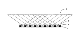
図1において、1は指(生体)を模式的に示している。この撮像光学系100は、指1の内部の静脈2を被写体として、その像を撮像して入力するものである。撮像光学系100は、光源6、レンズアレイ3、遮光部材(遮光手段)4、撮像素子(撮像手段)5及び光学的バンドパスフィルタ7から構成される。
In FIG. 1, 1 schematically shows a finger (living body). The imaging
レンズアレイ3は被写体像を結像させるためのもので、複数のレンズ3aがレンズ光軸と略直交する平面内に二次元アレイ配列されたものである。ただし、レンズ3aを一次元アレイ配列する態様もとり得るものであり、かかる態様も本実施形態に包含される。
The
本発明によれば、レンズアレイ3の各レンズ3aは、被写体側に0又は負のパワーを持つ面を有し、像面側(図中、下面側)に正のパワーを持つ面を有するレンズとされる。本実施形態においては、図示のように、レンズ3aとして像面側に凸面を向けた平凸レンズが用いられる。その凸面は球面でも非球面でもよく、非球面とするとレンズ3aの光学特性を向上させる設計の自由度が大きくなる。
According to the present invention, each
遮光部材4は、レンズアレイ3の各レンズ3aを通過した光線の像面上でのクロストークを防止し、ゴーストやフレアなどのノイズ光を抑制するためのものである。本実施形態の遮光部材4は、レンズアレイ3の各レンズ3aから像面までの高さを持ち、各レンズ3aに対応した開口部(通し穴)が二次元アレイ配列された構造であり、各開口部は正方形断面形状を有する。なお、遮光手段として、レンズアレイ3の各レンズ3aに開口部が対応したピンホールアレイでもよいし、各レンズ3aに対応した開口部が形成された透明平行平板の上面又は下面あるいは上下両面に不透明膜を蒸着等で成膜したものであってもよい。
The
撮像素子5は、レンズアレイ3の各レンズ3aにより結像される像(個眼画像)の集合である複眼画像を撮像するための撮像手段であり、具体的には例えば受光素子5aが二次元アレイ配列されたCCD撮像素子やCMOS撮像素子が用いられる。ここでは、撮像素子5は、受光素子5aによる光電変換信号のゲインを調整したりアナログ信号からデジタル信号へ変換したりする回路を内蔵し、撮像画像をデジタル画像データとして出力する構成のものとする。なお、撮像素子5は個々の個眼画像を複数画素からなる画像として撮像する。
The
光源6は、生体による吸収率が低い近赤外光を指(生体)1に照射するものであり、例えば発光ダイオード(LED)である。光源6により指1に照射された近赤外光は、指1の内部の静脈(被写体)2内の還元ヘモグロビンに吸収されるが、静脈2以外の部分では殆ど吸収されることがないため、静脈パターンを透視可能である。この静脈パターンはレンズアレイ3の各レンズ3aにより撮像素子5の撮像面に複眼画像として結像される。光学的バンドパスフィルタ7は、光源6より照射される近赤外光が含まれる所定の波長域の光のみを透過させるものである。この光学的バンドパスフィルタ7は、光源6以外の光源からのノイズ光の影響を除去するために設けられているものである。ノイズ光の入射を考慮する必要がない場合や、後記の第5の実施形態におけるように画像データの処理によってノイズ光の影響を除去する場合には、光学的バンドパスフィルタ7を省いてもよい。また、光学的バンドパスフィルタ7をレンズアレイ3の像面側、例えば撮像素子5の撮像面上に配置することも可能である。
The
なお、図1には光源6は1個のみ示されているが、被写体の領域を照明するような配置で複数個設置してもよい。光源6としてレーザダイオード(LD)を用いてもよい。また、図1では指1をレンズアレイ3と対向しない側の面(図中、上面)から照明するように光源6が配置されている。しかし、光源6より照射された近赤外光は指1の内部であらゆる方向に拡散されるため、指1を側面又は下面から照明するように光源6を配置してもよく、このようにしても静脈像を問題なく撮像可能である。また、光源6の発した近赤外光を指1へ向けて導く光導体を追加してもよい。
Although only one
撮像素子5は、レンズアレイ3により結像される静脈パターン(被写体像)の複眼画像を撮像し、それをデジタル画像データとして出力する。このデジタル画像データは、前処理部101によって前処理を施された後、再構成演算部102に転送される。前処理部101による前処理では、例えば、複眼画像における遮光部材4による影部分を除いた各個眼画像の領域を抽出し、各個眼画像に対し平滑化もしくは平均化処理によって孤立点等のノイズ成分を除去したり、静脈パターンが含まれる個眼画像を抽出したり、さらには個眼画像に対し静脈パターンを鮮明にするための強調処理を必要に応じて施す。再構成演算部102は、前処理後の複眼画像から後述する個眼画像間の視差を利用した再構成演算により単一画像を再構成する。この単一画像データは、後処理部103によって再構成ノイズの除去などの後処理を必要に応じて施された後、静脈(被写体)画像データとして認証演算部104へ入力される。ここまでが画像入力装置としての動作である。なお、上記の前処理と後処理は再構成処理の前・後処理である。すなわち、前処理部101、後処理部103は再構成演算部102とともに「再構成処理手段」を構成している。
The
認証演算部104においては、入力された静脈画像データより静脈パターンの特徴量を抽出し、その特徴量と、登録データメモリ105に記憶されている登録者の静脈パターンの特徴量とを比較することにより個人認証を行う。すなわち、抽出した特徴量と登録者の特徴量との距離が所定値以下ならば、被認証者(指1の持ち主)は登録者本人であると認証されるが、そうでなければ認証を拒否される。このような静脈パターンを利用する個人認証技術自体は公知であるので、これ以上の詳細は省略する。
The
レンズアレイ3は透明の樹脂やガラス材料で作られ、例えば、リフロー法や面積階調マスク法、研磨法などの加工法で作成され、あるいは、これらの加工法で作製した型を用いた成形加工などにより作製することができる。遮光部材4も樹脂、ガラス、金属などの材料を用いて同様に加工できるが、不透明材料を用いたり透明材料にコーティングを施したりして、光の透過や反射を抑制するようにする。
The
なお、図1においては、遮光部材4の開口部(通し穴)は、レンズ光軸と略直交する平面内での断面積がレンズ3aから撮像素子5の撮像面まで均一な形状となっているが、図2に示すように開口部4aを断面積が撮像面に近づくほど減少するテーパ形状としてもよい。このようなテーパ状の開口部4aとすると、図2に矢線として示すように、開口部4aに斜めに入射した光線が開口部内面で撮像素子5の撮像面へ反射されにくくなるため、開口部4aの内部反射によるフレアやゴーストを効果的に防ぐことができる。また、開口部4aの大きさに対して遮光壁部材4の必要な高さが大きくなると遮光部材4の加工が困難になる。この場合、加工が容易な高さの遮光部材4を作成し、これを高さ方向に積層し接着した構造とすることができる。図3は、加工が容易な高さの遮光部材4を2段積層する構造を示している。
In FIG. 1, the opening (through hole) of the
図4に、撮像光学系100において撮像される複眼画像のシミュレーション例を示す。図4(a)は複眼画像を生成するための原画像で、図4(b)が複眼画像である。複眼画像における個眼画像間に存在する黒部分は、遮光壁部材4による影である。個眼画像は、レンズアレイ3の各レンズ3aにより結像される画像であり、レンズ位置に応じて被写体の異なる部分が撮像される。図1において、2aは1つのレンズ3aによる視野を表しており個眼画像として観察される領域に相当する。また、2bは隣接するレンズ3a間で視野が重なる部分を表しており、これは図4(b)において隣接する個眼画像で共通する重複領域を表す。
FIG. 4 shows a simulation example of a compound eye image captured by the imaging
指の皮膚表面から静脈までの距離には個人差があるため、図1におけるレンズアレイ3から静脈2までの距離は、被認証者によって変化する。図1の状態に対し、図5(a)に示すように静脈2がレンズアレイ3に近づくと、あるいは遮光部材4の高さが大きくなると、隣接する個眼画像間での重複領域がなくなる。逆に図1の状態に対し、図5(b)に示すように静脈2がレンズアレイ3から遠ざかると、あるいは遮光部材4の高さが小さくなると、隣接する個眼画像間での重複領域が大きくなる。
Since there are individual differences in the distance from the finger skin surface to the vein, the distance from the
隣接個眼画像間での重複領域がないときは、複眼画像中の個々の個眼画像を抽出し、各個眼画像をレンズ3aによる上下左右の反転を元に戻してから単純に繋ぎ合わせることにより単一画像を再構成することができる。しかし、隣接個眼画像間での重複領域がある場合は、重複する領域の一方が無効になるため、個眼画像を単純に繋ぎ合わせる方法で単一画像を再構成すると、画像が小さくなり画像を構成する画素数が減るため解像力が低下する。また、図5(b)のように静脈がレンズアレイから遠ざかると、重複領域が増えて無効画素が増えると同時に撮像光学系の光学倍率が低下して静脈パターン像が小さくなるため、さらに解像力が低下する。
When there is no overlapping area between adjacent single-eye images, individual single-eye images in the compound-eye image are extracted, and each single-eye image is simply connected by reversing the up-down and left-right inversion by the
本実施形態においては、そのような無効画素の増加や光学倍率の低下に伴う解像力低下を補償するために、再構成演算部102で以下に説明するような個眼画像間の視差を利用した複眼画像から単一画像への再構成処理を行う。
In the present embodiment, in order to compensate for such a decrease in resolving power due to an increase in invalid pixels and a decrease in optical magnification, the
個眼画像間にはレンズ3aと静脈2つまり被写体との位置関係に起因した視差が存在するため、各個眼画像は視差に伴い少しずつシフトした画像となる。なお、本明細書において、個眼画像間の「視差」とは、複眼画像の中で基準とした個眼画像に対する各個眼画像のシフト量(単位は長さ)を表す。個眼画像の視差を利用すると、個眼画像における1つの画素に埋もれた被写体の構造を再現することができる。個眼画像間の視差の検出には、例えば次の(1)式で得られる個眼画像間の輝度偏差の二乗和を用いることができる。
Since there is a parallax due to the positional relationship between the

上述したように、図6でEが最小となるときのPx,Pyがx,y方向における個眼画像の基準個眼画像に対する視差である。視差の大きさが撮像素子5の画素サイズより小さくなることが考えられる場合は、視差の大きさが画素サイズあるいは画素サイズの整数倍になるように個眼画像を拡大し、すなわち個眼画像の構成画素数を増やし、拡大した個眼画像間の輝度偏差の最小二乗和から視差を求めればよい。その場合の個眼画像の拡大では、隣接画素を参照しながら各画素の輝度を決める補間演算を用いる必要がある。拡大率は、光学倍率とレンズアレイ3のレンズピッチ、撮像素子5の画素サイズから視差のおおよその値を推定できるため、推定した視差が画素サイズ分の長さになるように拡大率を決めればよい。レンズアレイ3のレンズピッチの加工精度が十分高い場合は、被写体のレンズアレイ3からの距離がわかれば、各個眼画像間の視差は幾何学的に算出可能である。そのため、1組の個眼画像間の視差を検出し、次の(2)式に基づき各個眼画像間の視差を算出してもよい。(2)式において、δは任意の個眼画像の視差、Δは実際に検出した個眼画像の視差、Nは画像内のx又はy方向(横又は縦方向)における基準個眼画像の中心から視差を検出した個眼画像の中心までの距離、nは基準個眼画像の中心から任意の個眼画像の中心までの距離をそれぞれ表す。
As described above, P x and P y when E is the minimum in FIG. 6 are parallaxes of the single-eye image with respect to the reference single-eye image in the x and y directions. When the size of the parallax is considered to be smaller than the pixel size of the
図7は単一画像の再構成方法の説明図である。図7において、複眼画像9における各個眼画像9aから画素輝度を取り出し、仮想空間における再構成画像8の該個眼画像の位置及び視差に応じて決まる位置に、取り出した画素輝度を配置する。各個眼画像の全画素について同様の画素輝度の配置を繰り返すことにより再構成画像8を得ることができる。
FIG. 7 is an explanatory diagram of a method for reconstructing a single image. In FIG. 7, pixel brightness is extracted from each single-eye image 9a in the compound-
なお、視差の大きさや遮光部材の影などの影響で再構成画像8に輝度が欠失した画素が生じるときは、その隣接画素の輝度を参照して補間する。視差が画素サイズより小さいときは、視差の大きさが画素サイズあるいは画素サイズの整数倍になるように再構成画像を拡大し、すなわち再構成画像の構成画素数を増やしてから同様の画素輝度配置を行えばよい。
In addition, when a pixel with lost luminance is generated in the
図8に再構成演算部102における処理フローの一例を示す。まず、複眼画像を取得する(ステップS1)。次に、前処理で抽出された静脈パターンが含まれている個眼画像の中から視差検出のための基準個眼画像を設定する(ステップS2)。この基準個眼画像に対する各個眼画像の視差を検出する(ステップS3)。ただし、静脈パターンが含まれない個眼画像に関しては、前記(2)式により視差を参照する。そして、視差を利用して複眼画像から単一画像への再構成演算を行い(ステップS4)、再構成した単一画像を出力する(ステップS5)。このような再構成処理により、画素に埋もれた被写体の構造を再現でき、被写体が遠くなって解像力が低下する場合でも解像力を向上させた単一像を取得することができる。
FIG. 8 shows an example of a processing flow in the
なお、個眼画像間の重複が小さい場合は、検出される視差が非常に小さくなったり異常値になったりすることがある。そこで、視差の大きさに関する閾値を設定しておき、例えばステップS4において、視差と閾値との比較判定を行い、視差が閾値未満の場合には複眼画像中の個眼画像を上下左右反転を元に戻して単純に繋ぎ合わせることにより単一画像を再構成し、視差が閾値以上の場合には上述したような視差を利用した再構成処理を行うようにしてもよい。 In addition, when the overlap between single-eye images is small, the detected parallax may become very small or become an abnormal value. Therefore, a threshold value regarding the magnitude of the parallax is set, and in step S4, for example, a comparison determination between the parallax and the threshold value is performed. It is also possible to reconstruct a single image by simply joining them back together and to perform a reconstruction process using parallax as described above when the parallax is greater than or equal to the threshold.
上に述べたような個眼画像間の視差を利用した再構成処理を可能にするためには、被写体からレンズアレイ3までの距離が所定の許容範囲内にあるときに、撮像素子5により撮像された隣接する個眼画像が被写体の共通部分を1画素以上共有する必要がある。そのために、レンズアレイ3を設計する段階で、レンズアレイ3から被写体までの距離が所定の許容距離範囲内で最小となったときに、隣接する個眼画像が常に重複領域を持つように、遮光部材4の高さ及びレンズアレイ3のレンズ3aの間隔が設定される。あるいは、レンズアレイ3から被写体までの距離が所定の許容距離範囲の最小値より小さくならないように調整するための透明平板(不図示)が指(生体)とレンズアレイ3との間に、例えば光学的バンドパスフィルタ7の上面に設置され、あるいは、光学的バンドパスフィルタ7を省く場合には、それに代えて該透明平板が設置される。このようにすると、常に重複領域を有する複眼画像を取得できるため、上に述べたような視差の閾値との比較判定により再構成処理方法を変更する必要がなくなる。そして、被写体距離の変化は視差に反映されるため、視差を利用した再構成処理によって、皮膚の厚みの個人差などにより生じる被写体距離の変化にも容易に対応できる。
In order to enable reconstruction processing using parallax between single-eye images as described above, imaging is performed by the
以上では、指内部の静脈パターンの入力と、静脈パターンを利用した個人認証を行う場合について説明した。しかし、本実施形態は、掌の静脈パターンや指の真皮指紋パターンを撮像して個人認証を行う用途にも利用可能であり、さらには非侵襲の血糖値計測のための生体内部情報を撮像する用途にも応用可能である。 In the above, the case where the input of the vein pattern inside the finger and the personal authentication using the vein pattern has been described. However, the present embodiment can also be used for applications in which palm vein patterns and finger dermal fingerprint patterns are imaged to perform personal authentication, and furthermore, in-vivo information for noninvasive blood glucose measurement is captured. It can also be applied to applications.
なお、図15に示すように、レンズアレイ3のバックフォーカスを短くすると光学倍率を小さくでき、より広い視野を確保できる。被写体サイズが大きい場合、汎用の撮像素子が使用できなくなり、特殊な撮像素子を使用せざるを得なくなるため装置コストが増大する。このようなコスト増加を抑えるためには、被写体サイズと汎用の撮像素子のサイズとから必要な光学倍率を設定し、汎用の撮像素子で被写体全体の像を撮像可能にするとよい。図15ではレンズアレイのみで倍率を落とす例であるが、被写体の像を縮小するための別の光学系を付加することも可能である。
As shown in FIG. 15, when the back focus of the
[第2の実施形態]
図9は本発明の第2の実施形態に係る画像入力装置及び個人認証装置の説明図である。本実施形態は、レンズアレイ3の各レンズ3aによる像劣化の補正(MTF補正)のための補正処理手段を構成する補正演算部201とメモリ202が追加されている点が前記第1の実施形態と相違し、これ以外の構成は前記第1の実施形態と同様である。メモリ202には、凸面を像面側に向けた平凸レンズ3aに関する光学伝達関数(OTF)データが予め格納されている。
[Second Embodiment]
FIG. 9 is an explanatory diagram of an image input device and a personal authentication device according to the second embodiment of the present invention. In the present embodiment, the
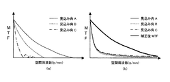
図10に、レンズ3aのような平凸レンズの光学伝達関数のゲインであるMTFと被写体見込み角との関係を、レンズの凸面を被写体側に向けた場合と像面側に向けた場合について例示する。
FIG. 10 illustrates the relationship between the MTF, which is the gain of the optical transfer function of a plano-convex lens such as the
図10(a)は凸面を被写体側に向けた平凸レンズのMTF特性を示し、図10(b)は本発明におけるレンズ3aのように凸面を像面側に向けた平凸レンズのMTF特性を示している。図10(a),(b)における細実線、点線、一点鎖線はレンズに入射する光線角の違い、すなわち被写体の見込み角の違いを表している。図10(b)における太実線は補正後のMTF特性を示している。
FIG. 10A shows the MTF characteristics of a plano-convex lens with the convex surface facing the object side, and FIG. 10B shows the MTF characteristics of a plano-convex lens with the convex surface facing the image surface side like the
平凸レンズの凸面を被写体側に向けた場合、図10(a)に見られるように、ある見込み角では高空間周波数帯まで高いMTFが得られるが、見込み角が変わるとMTF及びカットオフ周波数はともに大きく変化し、像は劣化する。許容見込み角全体にわたって高いMTFとカットオフ周波数を保持するには、許容見込み角が非常に狭くなったり、複数枚のレンズや複雑な非球面形状が必要になったりして、簡単な構成で広い見込み角にわたって性能を保持するのは困難である。MTFが有限な範囲では補正演算によりMTF特性を向上させることもできるが、図10(a)の場合、見込み角によりMTFの変化が大きいため、見込み角ごとに補正をかける必要があり、補正のための処理負荷が著しく大きくなる。また見、込み角に伴ってMTFが0に落ち込みやすいため、補正可能な見込み角の範囲も限定されてしまう。 When the convex surface of the plano-convex lens is directed to the subject side, as seen in FIG. 10A , a high MTF up to a high spatial frequency band can be obtained at a certain prospective angle, but when the prospective angle changes, the MTF and the cut-off frequency are Both change greatly and the image deteriorates. To maintain high MTF and cutoff frequency throughout permissible visual angle is or very narrow tolerance apparent angle, and or require multiple lenses or complex aspheric shape, a simple structure It is difficult to maintain the performance over a wide range of angles. In the range where the MTF is finite, the MTF characteristic can be improved by the correction calculation . However, in the case of FIG. 10A , since the change of the MTF is large depending on the expected angle, it is necessary to apply correction for each expected angle. Therefore, the processing load for remarkably increases. In addition, since the MTF is likely to drop to 0 with the included angle, the range of the expected angle that can be corrected is also limited.
一方、本発明におけるレンズ3aのように、凸面を像面側に向けた平凸レンズの場合、図10(b)に見られるように、MTFは全体的に低くなるが、見込み角に伴うMTFの変化は小さく、またカットオフ周波数も大きく変わらない。MTFの補正演算を前提にして、レンズの凸面を像面側に向けた構成で、MTFが有限でかつ均一になるように面形状を最適化することにより、小さい処理負荷で広い見込み角にわたってMTF性能を保持することができる。例えば図10(b)の太実線のようなMTF特性に容易に補正することができる。以上は、MTFについて述べたが、凸面を像面側に向けた場合には、凸面を被写体側に向けた場合に比べ、歪曲や湾曲といった面内誤差も減少する。以上に述べたことは、被写体側に負のパワーの面を有し、像面側に正のパワーを持つ面を有するレンズについても同様に当てはまる。
On the other hand, in the case of a plano-convex lens having a convex surface directed to the image surface side, like the
次に、補正演算部201におけるMTF補正処理について説明する。なお、補正演算部201は、補正演算に先立ち、撮像素子5により撮像された複眼画像における遮光部材4による影の部分を除いた各個眼画像の抽出を行う。したがって、前処理部101では、影部分を除いた個眼画像を抽出する処理を行う必要はない。
Next, the MTF correction process in the
レンズ3aで劣化を受けた被写体の像、すなわち撮像された複眼画像における個々の個眼画像の強度データは次の(3)式で表される。
The intensity data of the individual eye image in the image of the subject that has been deteriorated by the
補正演算部201は、あらかじめ計算してメモリ202に記憶されているレンズ3aに関する光学伝達関数データOTFを用いて、複眼画像に対し各個眼画像毎に次の(4)式の演算によりレンズ3aによる像劣化を補正し、MTFを向上させた個眼画像(の集合である複眼画像)を生成する。(4)式において、Rは補正後の個眼画像の強度データ、αは除算時のゼロ割やノイズ増幅を抑えるための定数である。
The
本実施形態の変形例によれば、レンズ3aによる像劣化の補正(MTF補正)のための補正処理手段は、前処理部101の前段ではなく後処理部103の後段に配置される。すなわち、補正演算部201に対応した補正演算部が、後処理部103と認証演算部104との間に挿入され、この補正演算部には光学伝達関数データを格納したメモリが接続され、再構成された単一画像に対し像劣化の補正処理(MTF補正)が施される。単一画像に対する補正処理は1回で済むので、個眼画像単位で補正処理を行うようりも一般的に演算時間を短縮できる利点がある。ただし、補正処理に用いられる光学伝達関数データは個々のレンズ3aに関するものであって、個々の個眼画像の補正に適用すべきものであるから、単一画像に対する補正処理では、個眼画像毎に補正処理を施す場合に比べると補正誤差のある程度の増加は避けられない。
According to the modification of the present embodiment, the correction processing means for correcting image degradation (MTF correction) by the
[第3の実施形態]
レンズの光学伝達関数は被写体距離によっても変化し、特に本発明の画像入力装置のように被写体がレンズアレイ3に近い撮像光学系の場合、被写体距離の変動に伴う光学伝達関数の変化が大きくなりやすい。
[Third Embodiment]
The optical transfer function of the lens also changes depending on the subject distance. In particular, in the case of an imaging optical system in which the subject is close to the
図10(b)の場合と同様の凸面を像面側に向けた平凸レンズにおける被写体距離の違いによるMTFの変化の例を図11に示す。図11においては、所定の被写体見込み角で、被写体距離がA,B,CのときのMTF特性が細実線、点線、一点鎖線により示されている。この例から分かるように、被写体距離の変動が無視できない場合には、特定の被写体距離での光学伝達関数データに基づいて像劣化補正(MTF補正)を行ったのでは補正誤差が大きくなってしまう。補正誤差を減らすためには、異なった被写体距離での光学伝達関数データを予め用意しておき、像劣化補正に用いる光学伝達関数データを被写体距離に応じて選択するのがよい。このような被写体距離に応じた像劣化補正によれば、例えば図11に太実線で示すような適切なMTF特性に補正することができる。 FIG. 11 shows an example of a change in MTF due to a difference in subject distance in a plano-convex lens in which the same convex surface as in FIG. 10B is directed to the image surface side. In FIG. 11, the MTF characteristics when the subject distance is A, B, and C at a predetermined subject prospect angle are indicated by a thin solid line, a dotted line, and a one-dot chain line. As can be seen from this example, when the variation in the subject distance cannot be ignored, the correction error becomes large if the image deterioration correction (MTF correction) is performed based on the optical transfer function data at the specific subject distance. . In order to reduce the correction error, it is preferable to prepare optical transfer function data at different subject distances in advance and select the optical transfer function data used for image degradation correction according to the subject distance. According to such image degradation correction according to the subject distance, it is possible to correct to an appropriate MTF characteristic as shown by a thick solid line in FIG. 11, for example.
図12は本発明の第3の実施形態に係る画像入力装置及び個人認証装置の説明図である。本実施形態においては、上に述べたような被写体距離に応じた像劣化補正を実施するため、被写体距離(被写体2からレンズアレイ3までの距離)を検出する被写体距離検出部(距離検出手段)301が追加される。また、メモリ202には、複数の異なった被写体距離でのレンズ3aに関する光学伝達関数データが予め格納されている。そして、補正演算部201では、被写体距離検出部301により検出された被写体距離に最も近い被写体距離に対応した光学伝達関数データをメモリ202より読み込み、この光学伝達関数データに基づいて、複眼画像に対し個眼画像毎に像劣化の補正(MTF補正)を施す。これ以外の構成は前記第2の実施形態と同様である。
FIG. 12 is an explanatory diagram of an image input device and a personal authentication device according to the third embodiment of the present invention. In this embodiment, a subject distance detection unit (distance detection means) that detects a subject distance (a distance from the subject 2 to the lens array 3) in order to perform image deterioration correction according to the subject distance as described above. 301 is added. The
前記第1の実施形態に関連して説明したように、被写体距離に応じて個眼画像間での重複領域が変化する(図5参照)。したがって、重複領域すなわち検出した視差を用いて三角測量の原理から被写体距離を算出することができる。本実施形態に係る被写体距離検出部301は、そのような方法を採用するものであり、撮像素子5によって撮像された複眼画像における個眼画像間の視差を検出し、この視差を用い三角測量の原理により被写体距離を算出する。なお、被写体距離検出のためには2つの個眼画像間の視差を検出すればよく、全ての個眼画像間の視差を検出する必要はない。また、個眼画像間の視差の検出方法は既に説明した方法によればよい。
As described in relation to the first embodiment, the overlapping area between the single-eye images changes according to the subject distance (see FIG. 5). Therefore, the subject distance can be calculated from the principle of triangulation using the overlapping region, that is, the detected parallax. The subject
本実施形態の変形例によれば、レンズ3aによる像劣化の補正(MTF補正)のための補正処理手段は、前処理部101の前段ではなく後処理部103の後段に配置される。すなわち、補正演算部201に対応した補正演算部が、後処理部103と認証演算部104との間に挿入され、この補正演算部には光学伝達関数データを格納したメモリが接続され、被写体距離検出部301により検出された被写体距離に対応した光学伝達関数データを用いて、再構成された単一画像に対し像劣化の補正処理(MTF補正)が施される。単一画像に対する補正処理は1回で済むので、個眼画像単位で補正処理を行うようりも一般的に演算時間を短縮できる利点がある。ただし、補正処理に用いられる光学伝達関数データは個々のレンズ3aに関するものであって、個々の個眼画像の補正に適用すべきものであるから、単一画像に対する補正処理では、個眼画像毎に補正処理を施す場合に比べると補正誤差のある程度の増加は避けられない。
According to the modification of the present embodiment, the correction processing means for correcting image degradation (MTF correction) by the
[第4の実施形態]
図13は本発明の第4の実施形態に係る画像入力装置及び個人認証装置の説明図である。本実施形態では、光源6から照射される近赤外光以外の外部光(バイアス光)によるバイアス成分を除去した複眼画像データを得るため、バイアス成分除去処理部(バイアス成分除去処理手段)401と、光源6の駆動の制御等を行うための制御部(制御手段)402が設けられる。403は撮像素子5を駆動する撮像素子駆動部である。これ以外の構成は、図示しないが、前記第1の実施形態、前記第2の実施形態もしくはその変形形態、又は前記第3の実施形態もしくはその変形形態と同様である。なお、図13には光学的バンドパスフィルタ7が示されているが、これを省いてもよい。光学的バンドパスフィルタ7を省く場合、光学的バンドパスフィルタ7の位置に例えば被写体距離を調整するための、又はレンズアレイ3を保護するための透明平板部材を設けることができる。また、撮像素子駆動部403は、前記各実施形態においても当然に存在するものであるが、作用説明に特に必要とされていないため図示及び説明が省略されていた。
[Fourth Embodiment]
FIG. 13 is an explanatory diagram of an image input device and a personal authentication device according to the fourth embodiment of the present invention. In this embodiment, in order to obtain compound eye image data from which a bias component by external light (bias light) other than near-infrared light emitted from the
(第1の実施例)
本実施形態の第1の実施例によれば、制御部402は光源6の駆動電流をオン、オフ制御することにより光源6を断続的に発光させる。すなわち、光源6を断続的に発光又は消光させる。そして、光源6の発光時と消光時における複眼画像をそれぞれ撮像素子5で撮像させ、それぞれの複眼画像をバイアス成分除去処理部401に取り込ませるため、制御部402より光源6の発光、消光に同期したタイミング信号が撮像素子駆動部403及びバイアス成分除去処理部401へ与えられる。バイアス成分除去処理部401においては、光源6の発光時に撮像された複眼画像と、光源6の消光時に撮像された複眼画像との差分をとることにより、外部光によるバイアス成分が除去された、光源6の照明光による成分のみからなる複眼画像を生成する。
(First embodiment)
According to the first example of the present embodiment, the
(第2の実施例)
本実施形態の第2の実施例によれば、制御部402は光源6の駆動電流を正弦波状に変調することにより、光源6により照射される近赤外光の強度を正弦波状に変化させる。この近赤外光に外部光(バイアス光)も重畳するので、仮にそれら光がそのまま撮像素子5に入射するものとすると、画素ごとに図9に示すような光強度変調が連続的に得られる。画像内の任意の位置(x,y)における画素の強度は次の(5)式で表される。
(Second embodiment)
According to the second example of the present embodiment, the
変調周期を4等分する時間間隔で、例えば図9に示すt1、t2、t3、t4の各時点で画像を撮像すると、各時点で取得される画像強度は以下のように表される。 For example, when images are captured at time points t1, t2, t3, and t4 shown in FIG. 9 at time intervals that divide the modulation period into four equal parts, the image intensity acquired at each time point is expressed as follows.
[第5の実施形態]
本発明に係る個人認証装置は、その撮像光学系全体を薄型構造とすることができるため、様々な電子機器に容易に組み込むことができる。そして、個人認証装置による認証結果に応じて電子機器の動作を制御し、例えば電子機器の利用者制限を図ることができる。
[Fifth Embodiment]
The personal authentication apparatus according to the present invention can be easily incorporated into various electronic devices because the entire imaging optical system can have a thin structure. Then, the operation of the electronic device can be controlled according to the authentication result by the personal authentication device, and for example, the user of the electronic device can be restricted.
図16に、本発明に係る個人認証装置を組み込んだ小型情報端末(例えばPDA)とノートブックパソコンの例を示す。図16において、500が個人認証装置であるが、その指を載せる部分(例えば光学的バンドパスフィルタ7の部分)のみが表面に露出している。この小型情報端末やノートブックパソコンを利用しようとする者は、個人認証装置500の露出部分に指を載せて静脈パターンを読み取らせて認証させる。機器側では、例えば、その者が予め登録されている者と同一人であると認証されたならばログイン(login)を許可し、同一人であると認証されないときにはログインを拒否する制御を行う。
FIG. 16 shows an example of a small information terminal (for example, PDA) and a notebook personal computer incorporating the personal authentication device according to the present invention. In FIG. 16,
[その他]
前記第1乃至第4の実施形態における再構成処理手段、補正処理手段、被写体距離検出手段、バイアス成分除去処理手段、認証処理手段をソフトウェアで実現することも可能である。
[Others]
The reconstruction processing means, correction processing means, subject distance detection means, bias component removal processing means, and authentication processing means in the first to fourth embodiments can be realized by software.
前記第1乃至第4の実施形態に係る画像入力装置についての説明は、本発明に係る画像入力方法の実施形態の説明でもあることは明らかである。よって、画像入力方法の説明は繰り返さない。 It is obvious that the description of the image input device according to the first to fourth embodiments is also the description of the embodiment of the image input method according to the present invention. Therefore, the description of the image input method will not be repeated.
1 指(生体)
2 静脈(被写体)
3 レンズアレイ
3a レンズアレイ上のレンズ
4 遮光部材
5 撮像素子
6 光源
7 光学的バンドパスフィルタ
100 撮像光学系
101 前処理部
102 再構成演算部
103 後処理部
104 認証演算部
105 登録データメモリ
201 補正演算部
202 光学伝達関数データメモリ
301 被写体距離検出部
401 バイアス成分除去処理部
402 制御部
403 撮像素子駆動部
500 電子機器に組み込まれた個人認証装置
1 finger (living body)
2 Veins (subject)
DESCRIPTION OF
Claims (15)
前記生体に近赤外光を照射する光源と、A light source for irradiating the living body with near infrared light;
前記生体に対向する位置に設けられた、前記生体側に0又は負のパワーを持つ面を有しかつ像面側に正のパワーを持つ面を有する複数のレンズがアレイ配列されてなるレンズアレイと、A lens array in which a plurality of lenses having a surface having 0 or negative power on the living body side and a surface having positive power on the image plane side are arranged in an array arranged at a position facing the living body When,
前記レンズアレイの像面側に設けられた、前記複数のレンズのそれぞれにより結像される前記被写体の像(以下、この像を個眼画像と記す)の集合である複眼画像を撮像する撮像手段と、Image pickup means for picking up a compound eye image that is a set of images of the subject (hereinafter, this image is referred to as a single eye image) formed by each of the plurality of lenses provided on the image plane side of the lens array When,
前記被写体から前記レンズアレイまでの距離を検出する距離検出手段と、Distance detecting means for detecting a distance from the subject to the lens array;
予め用意された前記レンズに関する複数の光学伝達関数データの中から前記距離検出手段により検出された前記距離に応じて1の光学伝達関数データを選択し、該選択した光学伝達関数データに基づいて、前記撮像手段により撮像された複眼画像に対し各個眼画像毎に前記レンズによる像劣化の補正処理を行う補正処理手段と、According to the selected optical transfer function data, one optical transfer function data is selected according to the distance detected by the distance detecting means from a plurality of optical transfer function data relating to the lens prepared in advance. Correction processing means for performing correction processing of image degradation by the lens for each single-eye image with respect to the compound eye image captured by the imaging means;
前記補正処理手段により補正後の複眼画像から、その個眼画像間の視差を利用して単一画像を再構成する処理を行う再構成処理手段とを有し、Reconstructing processing means for performing processing for reconstructing a single image using parallax between the single-eye images from the compound eye image corrected by the correction processing means,
前記再構成処理手段により再構成された単一画像を前記被写体の画像として入力することを特徴とする画像入力装置。An image input apparatus for inputting a single image reconstructed by the reconstruction processing means as an image of the subject.
前記生体に近赤外光を照射する光源と、
前記生体に対向する位置に設けられた、前記生体側に0又は負のパワーを持つ面を有しかつ像面側に正のパワーを持つ面を有する複数のレンズがアレイ配列されてなるレンズアレイと、
前記レンズアレイの像面側に設けられた、前記複数のレンズのそれぞれにより結像される前記被写体の像(以下、この像を個眼画像と記す)の集合である複眼画像を撮像する撮像手段と、
前記撮像手段により撮像された複眼画像から、その個眼画像間の視差を利用して単一画像を再構成する処理を行う再構成処理手段と、
前記被写体から前記レンズアレイまでの距離を検出する距離検出手段と、
予め用意された前記レンズに関する複数の光学伝達関数データの中から前記距離検出手段により検出された前記距離に応じて1の光学伝達関数データを選択し、該選択した光学伝達関数データに基づいて、前記再構成処理手段により再構成された単一画像に対し前記レンズによる像劣化の補正処理を行う補正処理手段とを有し、
前記補正処理手段により補正処理後の単一画像を前記被写体の画像として入力することを特徴とする画像入力装置。 An image input device for inputting an image of a subject existing inside a living body ,
A light source for irradiating the living body with near infrared light;
A lens array in which a plurality of lenses having a surface having 0 or negative power on the living body side and a surface having positive power on the image plane side are arranged in an array arranged at a position facing the living body When,
Image pickup means for picking up a compound eye image that is a set of images of the subject (hereinafter, this image is referred to as a single eye image) formed by each of the plurality of lenses provided on the image plane side of the lens array When,
Reconstruction processing means for performing processing for reconstructing a single image from a compound eye image captured by the imaging means, using parallax between the single-eye images;
Distance detecting means for detecting a distance from the subject to the lens array;
According to the selected optical transfer function data, one optical transfer function data is selected according to the distance detected by the distance detecting means from a plurality of optical transfer function data relating to the lens prepared in advance. Correction processing means for performing correction processing of image deterioration by the lens on a single image reconstructed by the reconstruction processing means ,
An image input apparatus for inputting a single image after correction processing by the correction processing means as an image of the subject.
前記生体に近赤外光を照射する光源と、A light source for irradiating the living body with near infrared light;
前記光源を発光又は消光させる制御を行う手段と、Means for controlling the light source to emit or extinguish,
前記生体に対向する位置に設けられた、前記生体側に0又は負のパワーを持つ面を有しかつ像面側に正のパワーを持つ面を有する複数のレンズがアレイ配列されてなるレンズアレイと、A lens array in which a plurality of lenses having a surface having 0 or negative power on the living body side and a surface having positive power on the image plane side are arranged in an array arranged at a position facing the living body When,
前記レンズアレイの像面側に設けられた、前記複数のレンズのそれぞれにより結像される前記被写体の像(以下、この像を個眼画像と記す)の集合である複眼画像を撮像する撮像手段と、Image pickup means for picking up a compound eye image that is a set of images of the subject (hereinafter, this image is referred to as a single eye image) formed by each of the plurality of lenses provided on the image plane side of the lens array When,
前記光源の発光時に前記撮像手段により撮像された複眼画像と、前記光源の消光時に前記撮像手段により撮像された複眼画像との差分をとることにより、前記光源により照射された近赤外光以外の光によるバイアス成分を除去した複眼画像を生成するバイアス成分除去処理手段と、By taking the difference between the compound eye image captured by the image capturing means when the light source emits light and the compound eye image captured by the image capturing means when the light source is extinguished, other than near-infrared light emitted by the light source. Bias component removal processing means for generating a compound eye image from which the bias component by light is removed;
前記被写体から前記レンズアレイまでの距離を検出する距離検出手段と、Distance detecting means for detecting a distance from the subject to the lens array;
予め用意された前記レンズに関する複数の光学伝達関数データの中から前記距離検出手段により検出された前記距離に応じて1の光学伝達関数データを選択し、該選択した光学伝達関数データに基づいて、前記バイアス成分除去処理手段により生成されたバイアス成分除去後の複複眼画像に対し各個眼画像毎に前記レンズによる像劣化の補正処理を行う補正処理手段と、According to the selected optical transfer function data, one optical transfer function data is selected according to the distance detected by the distance detecting means from a plurality of optical transfer function data relating to the lens prepared in advance. Correction processing means for performing correction processing of image degradation by the lens for each single-eye image with respect to the compound eye image after the bias component removal generated by the bias component removal processing means;
前記補正処理手段により補正後の複眼画像から、その個眼画像間の視差を利用して単一画像を再構成する処理を行う再構成処理手段とを有し、Reconstructing processing means for performing processing for reconstructing a single image using parallax between the single-eye images from the compound eye image corrected by the correction processing means,
前記再構成処理手段により再構成された単一画像を前記被写体の画像として入力することを特徴とする画像入力装置。 An image input apparatus for inputting a single image reconstructed by the reconstruction processing means as an image of the subject.
前記生体に近赤外光を照射する光源と、A light source for irradiating the living body with near infrared light;
前記光源を発光又は消光させる制御を行う手段と、Means for controlling the light source to emit or extinguish,
前記生体に対向する位置に設けられた、前記生体側に0又は負のパワーを持つ面を有しかつ像面側に正のパワーを持つ面を有する複数のレンズがアレイ配列されてなるレンズアレイと、A lens array in which a plurality of lenses having a surface having 0 or negative power on the living body side and a surface having positive power on the image plane side are arranged in an array arranged at a position facing the living body When,
前記レンズアレイの像面側に設けられた、前記複数のレンズのそれぞれにより結像される前記被写体の像(以下、この像を個眼画像と記す)の集合である複眼画像を撮像する撮像手段と、Image pickup means for picking up a compound eye image that is a set of images of the subject (hereinafter, this image is referred to as a single eye image) formed by each of the plurality of lenses provided on the image plane side of the lens array When,
前記光源の発光時に前記撮像手段により撮像された複眼画像と、前記光源の消光時に前記撮像手段により撮像された複眼画像との差分をとることにより、前記光源により照射された近赤外光以外の光によるバイアス成分を除去した複眼画像を生成するバイアス成分除去処理手段と、By taking the difference between the compound eye image captured by the image capturing means when the light source emits light and the compound eye image captured by the image capturing means when the light source is extinguished, other than near-infrared light emitted by the light source. Bias component removal processing means for generating a compound eye image from which the bias component by light is removed;
前記バイアス成分除去処理手段により生成されたバイアス成分除去後の複眼画像から、その個眼画像間の視差を利用して単一画像を再構成する処理を行う再構成処理手段と、Reconstruction processing means for performing processing for reconstructing a single image using parallax between the single-eye images from the compound eye image after the bias component removal generated by the bias component removal processing means;
前記被写体から前記レンズアレイまでの距離を検出する距離検出手段と、Distance detecting means for detecting a distance from the subject to the lens array;
予め用意された前記レンズに関する複数の光学伝達関数データの中から前記距離検出手段により検出された前記距離に応じて1の光学伝達関数データを選択し、該選択した光学伝達関数データに基づいて、前記再構成処理手段により再構成された単一画像に対し前記レンズによる像劣化の補正処理を行う補正処理手段とを有し、According to the selected optical transfer function data, one optical transfer function data is selected according to the distance detected by the distance detecting means from a plurality of optical transfer function data relating to the lens prepared in advance. Correction processing means for performing correction processing of image deterioration by the lens on a single image reconstructed by the reconstruction processing means,
前記補正処理手段により補正処理後の単一画像を前記被写体の画像として入力することを特徴とする画像入力装置。An image input apparatus for inputting a single image after correction processing by the correction processing means as an image of the subject.
前記生体に対し近赤外光を照射する光源と、A light source for irradiating the living body with near infrared light;
前記光源に対し、前記生体に照射される近赤外光の強度を正弦波状に変化させる制御を行う手段と、Means for controlling the light source to change the intensity of near-infrared light applied to the living body in a sinusoidal shape;
前記生体に対向する位置に設けられた、前記生体側に0又は負のパワーを持つ面を有しかつ像面側に正のパワーを持つ面を有する複数のレンズがアレイ配列されてなるレンズアレイと、A lens array in which a plurality of lenses having a surface having 0 or negative power on the living body side and a surface having positive power on the image plane side are arranged in an array arranged at a position facing the living body When,
前記レンズアレイの像面側に設けられた、前記複数のレンズのそれぞれにより結像される前記被写体の像(以下、この像を個眼画像と記す)の集合である複眼画像を撮像する撮像手段と、Image pickup means for picking up a compound eye image that is a set of images of the subject (hereinafter, this image is referred to as a single eye image) formed by each of the plurality of lenses provided on the image plane side of the lens array When,
前記光源により前記生体に照射される近赤外光の強度の正弦波状変化周期内の複数の異なった位相時点で前記撮像手段によりそれぞれ撮像された複数の複眼画像から演算処理によって、前記光源により照射された近赤外光以外の光によるバイアス成分を除去した複眼画像を生成するバイアス成分除去処理手段と、Irradiated by the light source by arithmetic processing from a plurality of compound eye images respectively captured by the imaging means at a plurality of different phase time points within a sinusoidal change period of the intensity of near infrared light irradiated to the living body by the light source Bias component removal processing means for generating a compound eye image in which a bias component due to light other than near-infrared light is removed;
前記被写体から前記レンズアレイまでの距離を検出する距離検出手段と、Distance detecting means for detecting a distance from the subject to the lens array;
予め用意された前記レンズに関する複数の光学伝達関数データの中から前記距離検出手段により検出された前記距離に応じて1の光学伝達関数データを選択し、該選択した光学伝達関数データに基づいて、前記バイアス成分除去処理手段により生成されたバイアス成分除去後の複眼画像に対し各個眼画像毎に前記レンズによる像劣化の補正処理を行う補正処理手段と、According to the selected optical transfer function data, one optical transfer function data is selected according to the distance detected by the distance detecting means from a plurality of optical transfer function data relating to the lens prepared in advance. Correction processing means for performing correction processing of image deterioration by the lens for each single-eye image with respect to the compound eye image after the bias component removal generated by the bias component removal processing means;
前記補正処理手段により補正後の複眼画像から、その個眼画像間の視差を利用して単一画像を再構成する処理を行う再構成処理手段とを有し、Reconstructing processing means for performing processing for reconstructing a single image using parallax between the single-eye images from the compound eye image corrected by the correction processing means,
前記再構成処理手段により再構成された単一画像を前記被写体の画像として入力することを特徴とする画像入力装置。An image input apparatus for inputting a single image reconstructed by the reconstruction processing means as an image of the subject.
前記生体に近赤外光を照射する光源と、A light source for irradiating the living body with near infrared light;
前記光源に対し、前記生体に照射される近赤外光の強度を正弦波状に変化させる制御を行う手段と、Means for controlling the light source to change the intensity of near-infrared light applied to the living body in a sinusoidal shape;
前記生体に対向する位置に設けられた、前記生体側に0又は負のパワーを持つ面を有しかつ像面側に正のパワーを持つ面を有する複数のレンズがアレイ配列されてなるレンズアレイと、A lens array in which a plurality of lenses having a surface having 0 or negative power on the living body side and a surface having positive power on the image plane side are arranged in an array arranged at a position facing the living body When,
前記レンズアレイの像面側に設けられた、前記複数のレンズのそれぞれにより結像される前記被写体の像(以下、この像を個眼画像と記す)の集合である複眼画像を撮像する撮像手段と、Image pickup means for picking up a compound eye image that is a set of images of the subject (hereinafter, this image is referred to as a single eye image) formed by each of the plurality of lenses provided on the image plane side of the lens array When,
前記光源により前記生体に照射される近赤外光の強度の正弦波状変化周期内の複数の異なった位相時点で前記撮像手段によりそれぞれ撮像された複数の複眼画像から演算処理によって、前記光源により照射された近赤外光以外の光によるバイアス成分を除去した複眼画像を生成するバイアス成分除去処理手段と、Irradiated by the light source by arithmetic processing from a plurality of compound eye images respectively captured by the imaging means at a plurality of different phase time points within a sinusoidal change period of the intensity of near infrared light irradiated to the living body by the light source Bias component removal processing means for generating a compound eye image in which a bias component due to light other than near-infrared light is removed;
前記バイアス成分除去処理手段により生成されたバイアス成分除去後の複眼画像から、その個眼画像間の視差を利用して単一画像を再構成する処理を行う再構成処理手段と、Reconstruction processing means for performing processing for reconstructing a single image using parallax between the single-eye images from the compound eye image after the bias component removal generated by the bias component removal processing means;
前記被写体から前記レンズアレイまでの距離を検出する距離検出手段と、Distance detecting means for detecting a distance from the subject to the lens array;
予め用意された前記レンズに関する複数の光学伝達関数データの中から前記距離検出手段により検出された前記距離に応じて1の光学伝達関数データを選択し、該選択した光学伝達関数データに基づいて、前記再構成処理手段により再構成された単一画像に対し前記レンズによる像劣化の補正処理を行う補正処理手段とを有し、According to the selected optical transfer function data, one optical transfer function data is selected according to the distance detected by the distance detecting means from a plurality of optical transfer function data relating to the lens prepared in advance. Correction processing means for performing correction processing of image deterioration by the lens on a single image reconstructed by the reconstruction processing means,
前記補正処理手段により補正処理後の単一画像を前記被写体の画像として入力することを特徴とする画像入力装置。An image input apparatus for inputting a single image after correction processing by the correction processing means as an image of the subject.
前記画像入力装置により入力された被写体の画像に基づいて個人認証処理を行う認証処理手段とを有することを特徴とする個人認証装置。A personal authentication apparatus comprising authentication processing means for performing personal authentication processing based on an image of a subject input by the image input apparatus.
前記生体に近赤外光を照射する光源と、A light source for irradiating the living body with near infrared light;
前記生体に対向する位置に設けられた、前記生体側に0又は負のパワーを持つ面を有しかつ像面側に正のパワーを持つ面を有する複数のレンズがアレイ配列されてなるレンズアレイと、A lens array in which a plurality of lenses having a surface having 0 or negative power on the living body side and a surface having positive power on the image plane side are arranged in an array arranged at a position facing the living body When,
前記レンズアレイの像面側に設けられた、前記複数のレンズのそれぞれにより結像される前記被写体の像(以下、この像を個眼画像と記す)の集合である複眼画像を撮像する撮像手段と、からなる撮像光学系を用い、Image pickup means for picking up a compound eye image that is a set of images of the subject (hereinafter, this image is referred to as a single eye image) formed by each of the plurality of lenses provided on the image plane side of the lens array And an imaging optical system consisting of
前記被写体から前記レンズアレイまでの距離を検出し、Detecting the distance from the subject to the lens array;
予め用意された前記レンズに関する複数の光学伝達関数データの中から前記検出された前記距離に応じて1の光学伝達関数データを選択し、該選択した光学伝達関数データに基づいて、前記撮像手段により撮像された複眼画像に対し各個眼画像毎に前記レンズによる像劣化の補正処理を行い、One optical transfer function data is selected according to the detected distance from a plurality of optical transfer function data relating to the lens prepared in advance, and the imaging means is used based on the selected optical transfer function data. For the captured compound eye image, each lens image is corrected for image degradation by the lens,
前記補正処理により補正後の複眼画像から、その個眼画像間の視差を利用して単一画像を再構成する処理を行い、From the compound eye image corrected by the correction process, a process of reconstructing a single image using the parallax between the single-eye images is performed,
前記再構成する処理により再構成された単一画像を前記被写体の画像として入力することを特徴とする画像入力方法。An image input method comprising inputting a single image reconstructed by the reconstructing process as an image of the subject.
前記生体に近赤外光を照射する光源と、A light source for irradiating the living body with near infrared light;
前記生体に対向する位置に設けられた、前記生体側に0又は負のパワーを持つ面を有しかつ像面側に正のパワーを持つ面を有する複数のレンズがアレイ配列されてなるレンズアレイと、A lens array in which a plurality of lenses having a surface having 0 or negative power on the living body side and a surface having positive power on the image plane side are arranged in an array arranged at a position facing the living body When,
前記レンズアレイの像面側に設けられた、前記複数のレンズのそれぞれにより結像される前記被写体の像(以下、この像を個眼画像と記す)の集合である複眼画像を撮像する撮像手段と、からなる撮像光学系を用い、Image pickup means for picking up a compound eye image that is a set of images of the subject (hereinafter, this image is referred to as a single eye image) formed by each of the plurality of lenses provided on the image plane side of the lens array And an imaging optical system consisting of
前記光源を間欠的に発光させ、Causing the light source to emit light intermittently;
前記光源の発光時に前記撮像手段により撮像された複眼画像と、前記光源の消光時に前記撮像手段により撮像された複眼画像との差分をとることにより、前記光源により照射された近赤外光以外の光によるバイアス成分が除去された複眼画像を生成し、By taking the difference between the compound eye image captured by the image capturing means when the light source emits light and the compound eye image captured by the image capturing means when the light source is extinguished, other than near-infrared light emitted by the light source. Generate a compound eye image with the light bias component removed,
前記被写体から前記レンズアレイまでの距離を検出し、Detecting the distance from the subject to the lens array;
予め用意された前記レンズに関する複数の光学伝達関数データの中から前記検出された前記距離に応じて1の光学伝達関数データを選択し、該選択した光学伝達関数データに基づいて、前記バイアス成分が除去された複眼画像に対し各個眼画像毎に前記レンズによる像劣化の補正処理を行い、One optical transfer function data is selected according to the detected distance from a plurality of optical transfer function data relating to the lens prepared in advance, and the bias component is selected based on the selected optical transfer function data. For the removed compound eye image, the lens deterioration correction process by the lens is performed for each single-eye image,
前記補正処理により補正後の複眼画像から、その個眼画像間の視差を利用して単一画像を再構成する処理を行い、From the compound eye image corrected by the correction process, a process of reconstructing a single image using the parallax between the single-eye images is performed,
前記再構成の処理により再構成された単一画像を前記被写体の画像として入力することを特徴とする画像入力方法。An image input method, wherein a single image reconstructed by the reconstruction process is input as an image of the subject.
前記生体に近赤外光を照射する光源と、A light source for irradiating the living body with near infrared light;
前記生体に対向する位置に設けられた、前記生体側に0又は負のパワーを持つ面を有しかつ像面側に正のパワーを持つ面を有する複数のレンズがアレイ配列されてなるレンズアレイと、A lens array in which a plurality of lenses having a surface having 0 or negative power on the living body side and a surface having positive power on the image plane side are arranged in an array arranged at a position facing the living body When,
前記レンズアレイの像面側に設けられた、前記複数のレンズのそれぞれにより結像される前記被写体の像(以下、この像を個眼画像と記す)の集合である複眼画像を撮像する撮像手段と、からなる撮像光学系を用い、Image pickup means for picking up a compound eye image that is a set of images of the subject (hereinafter, this image is referred to as a single eye image) formed by each of the plurality of lenses provided on the image plane side of the lens array And an imaging optical system consisting of
前記光源より照射される近赤外光の強度を正弦波状に変化させ、Change the intensity of near infrared light irradiated from the light source in a sine wave shape,
前記光源により照射される近赤外光の強度の正弦波状変化周期内の複数の異なった位相時点で前記撮像手段によりそれぞれ撮像された複数の複眼画像から演算処理によって、前記光源により照射された近赤外光以外の光によるバイアス成分が除去された複眼画像を生成し、The near-infrared light irradiated by the light source is calculated from a plurality of compound-eye images respectively captured by the imaging means at a plurality of different phase time points within a sinusoidal change period of the intensity of near-infrared light irradiated by the light source. Generate a compound eye image from which the bias component due to light other than infrared light is removed,
前記被写体から前記レンズアレイまでの距離を検出し、Detecting the distance from the subject to the lens array;
予め用意された前記レンズに関する複数の光学伝達関数データの中から前記検出された前記距離に応じて1の光学伝達関数データを選択し、該選択した光学伝達関数データに基づいて、前記バイアス成分が除去された複眼画像に対し各個眼画像毎に前記レンズによる像劣化の補正処理を行い、One optical transfer function data is selected according to the detected distance from a plurality of optical transfer function data relating to the lens prepared in advance, and the bias component is selected based on the selected optical transfer function data. For the removed compound eye image, the lens deterioration correction process by the lens is performed for each single-eye image,
前記補正処理により補正後の複眼画像から、その個眼画像間の視差を利用して単一画像を再構成する処理を行い、From the compound eye image corrected by the correction process, a process of reconstructing a single image using the parallax between the single-eye images is performed,
前記再構成の処理により再構成された単一画像を前記被写体の画像として入力することを特徴とする画像入力方法。An image input method, wherein a single image reconstructed by the reconstruction process is input as an image of the subject.
Priority Applications (7)
| Application Number | Priority Date | Filing Date | Title |
|---|---|---|---|
| JP2006278423A JP4864632B2 (en) | 2006-10-12 | 2006-10-12 | Image input device, image input method, personal authentication device, and electronic device |
| KR1020087013841A KR101027455B1 (en) | 2006-10-12 | 2007-10-05 | Image input apparatus, image input method, personal authentication apparatus, and electronic apparatus |
| US12/096,625 US8085312B2 (en) | 2006-10-12 | 2007-10-05 | Image input apparatus, image input method, personal authentication apparatus, and electronic apparatus |
| PCT/JP2007/070025 WO2008044781A1 (en) | 2006-10-12 | 2007-10-05 | Image input apparatus, image input method, personal authentication apparatus, and electronic apparatus |
| CNA2007800015522A CN101361095A (en) | 2006-10-12 | 2007-10-05 | Image input apparatus, image input method, personal authentication apparatus, and electronic apparatus |
| EP07829760A EP2054850A4 (en) | 2006-10-12 | 2007-10-05 | Image input apparatus, image input method, personal authentication apparatus, and electronic apparatus |
| TW096137707A TWI365417B (en) | 2006-10-12 | 2007-10-08 | Image input apparatus, image input method, personal authentication apparatus, and electronic apparatus |
Applications Claiming Priority (1)
| Application Number | Priority Date | Filing Date | Title |
|---|---|---|---|
| JP2006278423A JP4864632B2 (en) | 2006-10-12 | 2006-10-12 | Image input device, image input method, personal authentication device, and electronic device |
Publications (2)
| Publication Number | Publication Date |
|---|---|
| JP2008097327A JP2008097327A (en) | 2008-04-24 |
| JP4864632B2 true JP4864632B2 (en) | 2012-02-01 |
Family
ID=39282966
Family Applications (1)
| Application Number | Title | Priority Date | Filing Date |
|---|---|---|---|
| JP2006278423A Expired - Fee Related JP4864632B2 (en) | 2006-10-12 | 2006-10-12 | Image input device, image input method, personal authentication device, and electronic device |
Country Status (7)
| Country | Link |
|---|---|
| US (1) | US8085312B2 (en) |
| EP (1) | EP2054850A4 (en) |
| JP (1) | JP4864632B2 (en) |
| KR (1) | KR101027455B1 (en) |
| CN (1) | CN101361095A (en) |
| TW (1) | TWI365417B (en) |
| WO (1) | WO2008044781A1 (en) |
Cited By (1)
| Publication number | Priority date | Publication date | Assignee | Title |
|---|---|---|---|---|
| JP2008097328A (en) * | 2006-10-12 | 2008-04-24 | Ricoh Co Ltd | Image input device, personal authentication device, and electronic device |
Families Citing this family (48)
| Publication number | Priority date | Publication date | Assignee | Title |
|---|---|---|---|---|
| EP2087518A2 (en) * | 2006-11-17 | 2009-08-12 | Tessera North America | Internal noise reducing structures in camera systems employing an optics stack and associated methods |
| JP5312774B2 (en) * | 2006-12-15 | 2013-10-09 | 日立オートモティブシステムズ株式会社 | Thin authentication sensor |
| US8204282B2 (en) | 2007-09-14 | 2012-06-19 | Ricoh Company, Ltd. | Image input device and personal authentication device |
| JP5293950B2 (en) | 2008-03-04 | 2013-09-18 | 株式会社リコー | Personal authentication device and electronic device |
| JP4748257B2 (en) * | 2008-08-04 | 2011-08-17 | ソニー株式会社 | Biometric authentication device |
| JP4947072B2 (en) * | 2009-03-04 | 2012-06-06 | 三菱電機株式会社 | Image reading device |
| CN102113013A (en) | 2009-07-22 | 2011-06-29 | 松下电器产业株式会社 | Parallax detection apparatus, ranging apparatus and parallax detection method |
| EP2495699B1 (en) * | 2009-10-30 | 2019-07-10 | Fujitsu Frontech Limited | Biometric information registration method, biometric authentication method, and biometric authentication device |
| CN102131043B (en) * | 2010-01-19 | 2013-11-06 | 鸿富锦精密工业(深圳)有限公司 | Camera module |
| JP5707758B2 (en) * | 2010-07-13 | 2015-04-30 | ソニー株式会社 | Imaging apparatus, imaging system, surgical navigation system, and imaging method |
| DE102010031535A1 (en) * | 2010-07-19 | 2012-01-19 | Fraunhofer-Gesellschaft zur Förderung der angewandten Forschung e.V. | An image pickup device and method for picking up an image |
| JP5742272B2 (en) * | 2011-02-14 | 2015-07-01 | 株式会社リコー | Compound eye imaging device |
| JP5742348B2 (en) * | 2011-03-23 | 2015-07-01 | セイコーエプソン株式会社 | Imaging device |
| JP5170276B2 (en) * | 2011-03-31 | 2013-03-27 | カシオ計算機株式会社 | Image reconstruction device, image reconstruction method, and image reconstruction program |
| WO2013191546A1 (en) | 2012-06-19 | 2013-12-27 | Anteryon International B.V. | A method for forming a lens module and a camera module |
| JP6044239B2 (en) * | 2012-10-01 | 2016-12-14 | セイコーエプソン株式会社 | Imaging device and medical device |
| US9262666B2 (en) | 2012-10-04 | 2016-02-16 | Ib Korea Ltd. | Anti-shock relief print scanning |
| CN106054945A (en) * | 2013-09-10 | 2016-10-26 | 充梦霞 | Adaptive image information acquisition system |
| KR101376227B1 (en) * | 2013-09-17 | 2014-03-25 | 실리콘 디스플레이 (주) | Optical fingerprint sensor |
| KR102198852B1 (en) * | 2014-03-24 | 2021-01-05 | 삼성전자 주식회사 | Iris recognition apparatus and and mobile apparatus having the same |
| CN106163399B (en) * | 2014-03-31 | 2019-07-12 | 索尼公司 | Measuring device, measurement method, program and recording medium |
| WO2015151586A1 (en) | 2014-03-31 | 2015-10-08 | ソニー株式会社 | Measurement device, measurement method, program, and recording medium |
| CN104182727B (en) | 2014-05-16 | 2021-07-30 | 深圳印象认知技术有限公司 | Ultra-thin fingerprint and palm print acquisition device and fingerprint and palm print image acquisition method |
| CN104034768A (en) * | 2014-06-26 | 2014-09-10 | 无锡市崇安区科技创业服务中心 | Glucometer and blood glucose monitoring system |
| US10732771B2 (en) | 2014-11-12 | 2020-08-04 | Shenzhen GOODIX Technology Co., Ltd. | Fingerprint sensors having in-pixel optical sensors |
| WO2016125165A2 (en) * | 2015-02-05 | 2016-08-11 | Verifood, Ltd. | Spectrometry system with visible aiming beam |
| US9558392B2 (en) * | 2015-02-12 | 2017-01-31 | Korecen Co., Ltd. | Finger vein authentication system |
| JP6542904B2 (en) | 2015-03-25 | 2019-07-10 | アップル インコーポレイテッドApple Inc. | Electronic device comprising a pinhole array mask above an optical image sensor and related method |
| CN107004130B (en) * | 2015-06-18 | 2020-08-28 | 深圳市汇顶科技股份有限公司 | Optical sensor module under screen for sensing fingerprint on screen |
| US10282582B2 (en) | 2015-09-30 | 2019-05-07 | Apple Inc. | Finger biometric sensor for generating three dimensional fingerprint ridge data and related methods |
| JP2017099616A (en) * | 2015-12-01 | 2017-06-08 | ソニー株式会社 | Surgical control device, surgical control method and program, and surgical system |
| CN107292216A (en) * | 2016-03-31 | 2017-10-24 | 上海箩箕技术有限公司 | Optical fingerprint sensor module |
| CN109074475B (en) | 2016-05-23 | 2022-03-01 | 苹果公司 | Electronic device including pinhole array mask and related methods |
| CN109074474B (en) | 2016-05-23 | 2022-06-28 | 苹果公司 | Electronic device including processing circuitry for sensing images from spaced-apart subarrays and related methods |
| CN105893992A (en) * | 2016-05-31 | 2016-08-24 | 京东方科技集团股份有限公司 | Fingerprint identification structure and method and display device |
| US10462377B2 (en) | 2016-07-29 | 2019-10-29 | Nokia Of America Corporation | Single-aperture multi-sensor lensless compressive image acquisition |
| US20180035046A1 (en) * | 2016-07-29 | 2018-02-01 | Xin Yuan | Block-based lensless compressive image acquisition |
| CN106682473A (en) * | 2016-12-20 | 2017-05-17 | 深圳芯启航科技有限公司 | Method and device for identifying identity information of users |
| TWI631373B (en) * | 2017-05-05 | 2018-08-01 | 友達光電股份有限公司 | System and method for blood vessel scanning |
| US11460666B2 (en) | 2017-10-19 | 2022-10-04 | Sony Corporation | Imaging apparatus and method, and image processing apparatus and method |
| CN111386532B (en) | 2018-09-12 | 2023-09-08 | 指纹卡安娜卡敦知识产权有限公司 | Reconstruction of fingerprint sub-images |
| CN109284708A (en) * | 2018-09-12 | 2019-01-29 | 京东方科技集团股份有限公司 | A kind of fingerprint recognition device and display device |
| KR102142859B1 (en) * | 2018-10-16 | 2020-08-10 | 한국과학기술원 | Closest image photographing apparatus with microcamera array |
| KR20210019641A (en) * | 2019-08-12 | 2021-02-23 | 삼성전자주식회사 | Biometric information sensing module and electronic device including the same |
| TWI729813B (en) * | 2020-05-18 | 2021-06-01 | 友達光電股份有限公司 | Blood vessel image forming system |
| US11704929B2 (en) * | 2020-07-06 | 2023-07-18 | Visera Technologies Company Limited | Optical structure and method of fabricating the same |
| FR3133687B1 (en) * | 2022-03-18 | 2024-03-15 | Embodme | DEVICE AND METHOD FOR DETECTING AN OBJECT ABOVE A DETECTION SURFACE |
| WO2023175162A1 (en) * | 2022-03-18 | 2023-09-21 | Embodme | Device and method for detecting an object above a detection surface |
Family Cites Families (32)
| Publication number | Priority date | Publication date | Assignee | Title |
|---|---|---|---|---|
| US5193124A (en) * | 1989-06-29 | 1993-03-09 | The Research Foundation Of State University Of New York | Computational methods and electronic camera apparatus for determining distance of objects, rapid autofocusing, and obtaining improved focus images |
| JPH0721373A (en) | 1993-06-17 | 1995-01-24 | Asahi Optical Co Ltd | Individual identifying device |
| US5818956A (en) * | 1995-10-23 | 1998-10-06 | Tuli; Raja Singh | Extended fingerprint reading apparatus |
| US6259108B1 (en) * | 1998-10-09 | 2001-07-10 | Kinetic Sciences Inc. | Fingerprint image optical input apparatus |
| JP3821614B2 (en) * | 1999-08-20 | 2006-09-13 | 独立行政法人科学技術振興機構 | Image input device |
| JP2001358904A (en) | 2000-06-15 | 2001-12-26 | Nippon Sheet Glass Co Ltd | Line sensor module |
| JP2002092616A (en) * | 2000-09-20 | 2002-03-29 | Hitachi Ltd | Individual authentication device |
| JP2002171537A (en) * | 2000-11-30 | 2002-06-14 | Canon Inc | Compound image pickup system, image pickup device and electronic device |
| JP2002218160A (en) | 2001-01-19 | 2002-08-02 | Nippon Sheet Glass Co Ltd | Contact image sensor |
| JP2003060916A (en) * | 2001-08-16 | 2003-02-28 | Minolta Co Ltd | Image processor, image processing method, program and recording medium |
| JP2003143459A (en) * | 2001-11-02 | 2003-05-16 | Canon Inc | Compound-eye image pickup system and device provided therewith |
| JP3705766B2 (en) * | 2001-11-28 | 2005-10-12 | 独立行政法人科学技術振興機構 | Image input device |
| JP4387643B2 (en) * | 2002-07-31 | 2009-12-16 | 富士通株式会社 | Processing device with personal recognition function |
| US8190239B2 (en) * | 2002-09-03 | 2012-05-29 | Fujitsu Limited | Individual identification device |
| JP3770241B2 (en) * | 2003-03-04 | 2006-04-26 | 株式会社日立製作所 | Personal authentication device and personal authentication method |
| JP2004272821A (en) | 2003-03-12 | 2004-09-30 | Hitachi Ltd | Device for authenticating individual |
| US7539330B2 (en) * | 2004-06-01 | 2009-05-26 | Lumidigm, Inc. | Multispectral liveness determination |
| JP4347599B2 (en) * | 2003-04-10 | 2009-10-21 | オリンパス株式会社 | Personal authentication device |
| US7158659B2 (en) * | 2003-04-18 | 2007-01-02 | Avago Technologies Ecbu Ip (Singapore) Pte. Ltd. | System and method for multiplexing illumination in combined finger recognition and finger navigation module |
| JP4524250B2 (en) * | 2003-08-13 | 2010-08-11 | 日立オートモティブシステムズ株式会社 | Personal authentication device |
| JP2005176040A (en) | 2003-12-12 | 2005-06-30 | Canon Inc | Imaging device |
| JPWO2005069216A1 (en) | 2004-01-15 | 2010-02-25 | 松下電器産業株式会社 | Optical transfer function measurement method, image restoration method, and digital imaging apparatus |
| JP4322155B2 (en) | 2004-03-24 | 2009-08-26 | 株式会社リコー | Shape measuring apparatus and measuring method for movable object or stationary object |
| US7336372B2 (en) | 2004-09-14 | 2008-02-26 | Zvi Yaniv | Noninvasive optical imaging by speckle ensemble |
| JP2006135823A (en) * | 2004-11-09 | 2006-05-25 | Canon Inc | Image processor, imaging apparatus and image processing program |
| JP2007110588A (en) * | 2005-10-17 | 2007-04-26 | Funai Electric Co Ltd | Compound-eye imaging apparatus |
| JP2007156749A (en) | 2005-12-02 | 2007-06-21 | Ricoh Co Ltd | Image input device |
| JP4673202B2 (en) | 2005-12-06 | 2011-04-20 | 株式会社リコー | Image input device |
| JP2007304525A (en) | 2006-05-15 | 2007-11-22 | Ricoh Co Ltd | Image input device, electronic equipment, and image input method |
| JP4866147B2 (en) | 2006-05-22 | 2012-02-01 | 株式会社リコー | Image shift detection method and apparatus, and image input apparatus |
| US8175346B2 (en) * | 2006-07-19 | 2012-05-08 | Lumidigm, Inc. | Whole-hand multispectral biometric imaging |
| US8204282B2 (en) * | 2007-09-14 | 2012-06-19 | Ricoh Company, Ltd. | Image input device and personal authentication device |
-
2006
- 2006-10-12 JP JP2006278423A patent/JP4864632B2/en not_active Expired - Fee Related
-
2007
- 2007-10-05 WO PCT/JP2007/070025 patent/WO2008044781A1/en active Application Filing
- 2007-10-05 KR KR1020087013841A patent/KR101027455B1/en not_active IP Right Cessation
- 2007-10-05 US US12/096,625 patent/US8085312B2/en not_active Expired - Fee Related
- 2007-10-05 CN CNA2007800015522A patent/CN101361095A/en active Pending
- 2007-10-05 EP EP07829760A patent/EP2054850A4/en not_active Withdrawn
- 2007-10-08 TW TW096137707A patent/TWI365417B/en not_active IP Right Cessation
Cited By (1)
| Publication number | Priority date | Publication date | Assignee | Title |
|---|---|---|---|---|
| JP2008097328A (en) * | 2006-10-12 | 2008-04-24 | Ricoh Co Ltd | Image input device, personal authentication device, and electronic device |
Also Published As
| Publication number | Publication date |
|---|---|
| KR101027455B1 (en) | 2011-04-06 |
| WO2008044781A1 (en) | 2008-04-17 |
| TWI365417B (en) | 2012-06-01 |
| US8085312B2 (en) | 2011-12-27 |
| KR20080088591A (en) | 2008-10-02 |
| JP2008097327A (en) | 2008-04-24 |
| EP2054850A4 (en) | 2011-06-15 |
| EP2054850A1 (en) | 2009-05-06 |
| TW200834434A (en) | 2008-08-16 |
| CN101361095A (en) | 2009-02-04 |
| US20080316323A1 (en) | 2008-12-25 |
Similar Documents
| Publication | Publication Date | Title |
|---|---|---|
| JP4864632B2 (en) | Image input device, image input method, personal authentication device, and electronic device | |
| JP5293950B2 (en) | Personal authentication device and electronic device | |
| JP5067885B2 (en) | Image input device and personal authentication device | |
| JP4915859B2 (en) | Object distance deriving device | |
| KR101233013B1 (en) | Image photographing device, distance computing method for the device, and focused image acquiring method | |
| JP2009225064A (en) | Image input device, authentication device, and electronic apparatus having them mounted thereon | |
| US10791282B2 (en) | High dynamic range camera assembly with augmented pixels | |
| JP5229489B2 (en) | Biometric authentication device | |
| JP2008212311A (en) | Biometrics device | |
| JP2007074079A (en) | Image input device | |
| US8204282B2 (en) | Image input device and personal authentication device | |
| JP4802121B2 (en) | Biometric authentication device and authentication method using biometric authentication device | |
| EP4056947A1 (en) | Light projection apparatus | |
| US20200260021A1 (en) | Differentiated imaging using camera assembly with augmented pixels | |
| JP7160044B2 (en) | Electronics | |
| CN111279677A (en) | Image display device and image display method | |
| US11509803B1 (en) | Depth determination using time-of-flight and camera assembly with augmented pixels | |
| JP4953292B2 (en) | Image input device, personal authentication device, and electronic device | |
| US11497392B2 (en) | Extended depth of field intraoral imaging apparatus | |
| JP7247890B2 (en) | Electronic equipment and signal processing equipment | |
| JP5229490B2 (en) | Biometric authentication device | |
| JP4803676B2 (en) | Image input device and personal authentication device | |
| JP2009223526A (en) | Image input device and personal identification device | |
| JP2010092148A (en) | Image input device and personal authentication device | |
| JP2009098815A (en) | Image input device, authentication device, and electronic apparatus |
Legal Events
| Date | Code | Title | Description |
|---|---|---|---|
| A621 | Written request for application examination |
Free format text: JAPANESE INTERMEDIATE CODE: A621 Effective date: 20090707 |
|
| A131 | Notification of reasons for refusal |
Free format text: JAPANESE INTERMEDIATE CODE: A131 Effective date: 20110601 |
|
| A521 | Request for written amendment filed |
Free format text: JAPANESE INTERMEDIATE CODE: A523 Effective date: 20110727 |
|
| A131 | Notification of reasons for refusal |
Free format text: JAPANESE INTERMEDIATE CODE: A131 Effective date: 20110907 |
|
| A521 | Request for written amendment filed |
Free format text: JAPANESE INTERMEDIATE CODE: A523 Effective date: 20111014 |
|
| TRDD | Decision of grant or rejection written | ||
| A01 | Written decision to grant a patent or to grant a registration (utility model) |
Free format text: JAPANESE INTERMEDIATE CODE: A01 Effective date: 20111108 |
|
| A01 | Written decision to grant a patent or to grant a registration (utility model) |
Free format text: JAPANESE INTERMEDIATE CODE: A01 |
|
| A61 | First payment of annual fees (during grant procedure) |
Free format text: JAPANESE INTERMEDIATE CODE: A61 Effective date: 20111109 |
|
| FPAY | Renewal fee payment (event date is renewal date of database) |
Free format text: PAYMENT UNTIL: 20141118 Year of fee payment: 3 |
|
| R151 | Written notification of patent or utility model registration |
Ref document number: 4864632 Country of ref document: JP Free format text: JAPANESE INTERMEDIATE CODE: R151 |
|
| FPAY | Renewal fee payment (event date is renewal date of database) |
Free format text: PAYMENT UNTIL: 20141118 Year of fee payment: 3 |
|
| LAPS | Cancellation because of no payment of annual fees |