JP4863795B2 - Game machine - Google Patents

Game machine Download PDF

Info

Publication number
JP4863795B2
JP4863795B2 JP2006187817A JP2006187817A JP4863795B2 JP 4863795 B2 JP4863795 B2 JP 4863795B2 JP 2006187817 A JP2006187817 A JP 2006187817A JP 2006187817 A JP2006187817 A JP 2006187817A JP 4863795 B2 JP4863795 B2 JP 4863795B2
Authority
JP
Japan
Prior art keywords
game ball
ball
winning
game
area
Prior art date
Legal status (The legal status is an assumption and is not a legal conclusion. Google has not performed a legal analysis and makes no representation as to the accuracy of the status listed.)
Expired - Fee Related
Application number
JP2006187817A
Other languages
Japanese (ja)
Other versions
JP2008012152A (en
JP2008012152A5 (en
Inventor
高明 市原
勉 飯島
Current Assignee (The listed assignees may be inaccurate. Google has not performed a legal analysis and makes no representation or warranty as to the accuracy of the list.)
Daiichi Shokai Co Ltd
Original Assignee
Daiichi Shokai Co Ltd
Priority date (The priority date is an assumption and is not a legal conclusion. Google has not performed a legal analysis and makes no representation as to the accuracy of the date listed.)
Filing date
Publication date
Application filed by Daiichi Shokai Co Ltd filed Critical Daiichi Shokai Co Ltd
Priority to JP2006187817A priority Critical patent/JP4863795B2/en
Publication of JP2008012152A publication Critical patent/JP2008012152A/en
Publication of JP2008012152A5 publication Critical patent/JP2008012152A5/ja
Application granted granted Critical
Publication of JP4863795B2 publication Critical patent/JP4863795B2/en
Expired - Fee Related legal-status Critical Current
Anticipated expiration legal-status Critical

Links

Images

Description

本発明は、遊技盤の前面に形成されると共に遊技者の操作によって遊技球が打ち込まれる遊技領域と、該遊技領域内に配されて遊技球の入賞が可能な始動入賞口と、該始動入賞口への遊技球の入賞を検出する始動検出手段と、該始動検出手段による遊技球の検出に応じて所定の開閉動作が可能な開閉片、該開閉片の開放によって遊技球が進入可能となる進入口、該進入口から進入した遊技球を検出する進入検出手段、該進入検出手段によって検出された遊技球を受け入れる入賞空間、該入賞空間に入った遊技球を転動させて規定時間内で所定の演出を行う転動装置、該転動装置により転動させられた遊技球を受け入れ可能とされて遊技者に有利な特定遊技状態が発生し得る特定入賞領域及び前記特定遊技状態が発生しない通常入賞領域、前記特定入賞領域及び前記通常入賞領域における遊技球の受け入れを所定の周期をもって切り替える受入切替手段を有し、前記遊技領域内の前記始動入賞口とは異なる位置に配された可変入賞装置と、を備えた遊技機に関するものである。 The present invention relates to a game area formed on the front surface of a game board and into which a game ball is driven by a player's operation, a start prize opening arranged in the game area and capable of winning a game ball, and the start prize Start detecting means for detecting a winning of a game ball to the mouth, an opening / closing piece capable of performing a predetermined opening / closing operation in accordance with detection of the game ball by the start detecting means, and opening of the opening / closing piece allows the game ball to enter. An entrance, an entry detecting means for detecting a game ball that has entered from the entrance, a winning space for receiving the gaming ball detected by the entry detecting means, and rolling the gaming ball that has entered the winning space within a specified time rolling device for performing a predetermined effect, said transfer dynamic device specific winning region and the specific game state occurs is as capable of receiving the game ball that is allowed to roll an advantageous specific gaming state to the player that obtained caused by Not normal winning area, said A variable winning device having an acceptance switching means for switching the acceptance of game balls in the regular prize area and the normal prize area at a predetermined cycle, and being arranged at a position different from the start prize opening in the game area; It relates to a game machine.

従来、一般に、遊技機の一例としてのパチンコ機には、始動入賞口への入賞に基づいて可変入賞装置の開閉片を開放し、該可変入賞装置内に入った遊技球が特定入賞領域に入賞すると、遊技特典として特定遊技状態を発生する(例えば、可変入賞装置の開閉片を特別態様で開放する)ことで遊技者に多量の賞球を付与するものがある。また、このようなパチンコ機には、可変入賞装置内での遊技球の球流れに対する興趣を高めるために、該球流れと対応した演出表示を行う表示器を備えたもの(例えば、特許文献1参照)が提案されている。
特開2004−223167号公報(図2)
Conventionally, in general, a pachinko machine as an example of a gaming machine has an open / close piece of a variable winning device that is opened based on winning at a start winning opening, and a game ball that has entered the variable winning device wins a specific winning area. Then, there is one that gives a player a lot of prize balls by generating a specific gaming state as a gaming privilege (for example, opening an opening / closing piece of a variable winning device in a special manner). In addition, in such a pachinko machine, in order to enhance the interest in the ball flow of the game ball in the variable winning device, the pachinko machine is provided with a display that performs an effect display corresponding to the ball flow (for example, Patent Document 1) Have been proposed).
Japanese Patent Laying-Open No. 2004-223167 (FIG. 2)

ところで、上記特許文献1の構成では、可変入賞装置内での遊技球の球流れと、表示器での演出表示との関連性を高めるために、遊技領域内において表示器を可変入賞装置の近傍位置(具体的には、可変入賞装置の真上部分)に配置していた。また、遊技者の関心が最も高くなる可変入賞装置内での遊技球の球流れをクローズアップし且つ期待感を持続させるために(可変入賞装置内での遊技球の球流れ時間を長めにとるために)、遊技領域内で可変入賞装置が占める領域を大きめにとっていた。このため、可変入賞装置近傍に配された表示器は、必然的に占有領域が制限されてしまい(表示器が小型化されてしまい)、結果として、表示器の演出表示をダイナミックに行うことができず、遊技の興趣が低下していた。本発明は、上記した事情に鑑みなされたもので、その目的とするところは、遊技領域内での可変入賞装置の占有領域を制限することなく、表示器の演出表示をダイナミックに行うことで、遊技の興趣の低下が抑制できる遊技機を提供することにある。   By the way, in the structure of the said patent document 1, in order to raise the relevance with the ball | bowl flow of the game ball in a variable prize apparatus, and the display of an effect on a display, a display is made near the variable prize apparatus in a game area. It was placed at the position (specifically, the portion directly above the variable winning device). Also, in order to keep the ball flow of the game ball in the variable winning device where the player's interest is the highest, and to maintain the expectation (the longer the ball flow time of the game ball in the variable winning device) Therefore, the area occupied by the variable winning device in the game area has been increased. For this reason, the display device arranged in the vicinity of the variable prize winning device inevitably has a limited occupation area (the display device is downsized), and as a result, the display of the display device can be dynamically displayed. I couldn't do it, and the fun of the game was declining. The present invention has been made in view of the above-described circumstances, and the purpose of the present invention is to dynamically display an effect on the display without limiting the occupation area of the variable winning device in the game area. An object of the present invention is to provide a gaming machine that can suppress a decrease in the interest of games.

(解決手段1)
上記目的を達成するために、請求項1の発明においては、遊技盤の前面に形成されると共に遊技者の操作によって遊技球が打ち込まれる遊技領域と、該遊技領域内に配されて遊技球の入賞が可能な始動入賞口と、該始動入賞口への遊技球の入賞を検出する始動検出手段と、該始動検出手段による遊技球の検出に応じて所定の開閉動作が可能な開閉片、該開閉片の開放によって遊技球が進入可能となる進入口、該進入口から進入した遊技球を検出する進入検出手段、該進入検出手段によって検出された遊技球を受け入れる入賞空間、該入賞空間に入った遊技球を転動させて規定時間内で所定の演出を行う転動装置、該転動装置により転動させられた遊技球を受け入れ可能とされて遊技者に有利な特定遊技状態が発生し得る特定入賞領域及び前記特定遊技状態が発生しない通常入賞領域、前記特定入賞領域及び前記通常入賞領域における遊技球の受け入れを所定の周期をもって切り替える受入切替手段を有し、前記遊技領域内の前記始動入賞口とは異なる位置に配された可変入賞装置と、を備えた遊技機であって、前記可変入賞装置は、前記入賞空間の後壁部分に配されると共に、当該後壁部分のほぼ全体に表示画面が臨設されて演出表示を行う表示器を備え、前記転動装置は、前記入賞空間に入った遊技球を受け入れる球入口と、該球入口で受け入れた遊技球を前記特定入賞領域又は前記通常入賞領域に送り出す球出口とを有し、前記球入口での遊技球の受け入れを可能にすると共に前記表示画面の少なくとも前面一部を隠蔽する第一の位置と、当該隠蔽を解除する通常位置となる第二の位置との間で移動可能に設けられた可動通路部材とを備え、前記可動通路部材は、1個の遊技球を受け入れ可能な球受凹部が周方向に一定間隔を置いて複数個形成されると共にモータの駆動に基づいて常時、一方向に回動する円盤形状の球受回動部材と、該球受回動部材の上端側に設けられて前記入賞空間内に入った遊技球を前記複数個の球受凹部のいずれかに送り込む球受入口と、前記球受回動部材の下端側に設けられて前記球受回動部材の回動動作に伴って前記球受凹部内の遊技球を前記特定入賞領域又は前記通常入賞領域に排出する球排出口と、を備え、前記遊技機は、前記進入検出手段による遊技球の検出に基づいて、前記可動通路部材を前記第二の位置から前記第一の位置に移動させる制御を行う移動制御手段を備えることを特徴とする。
この場合、進入検出手段による遊技球の検出がないとき、即ち可変入賞装置への入賞がないときには、表示画面の隠蔽を解除する第二の位置に可動通路部材を移動させることで、入賞空間の後壁部分におけるほぼ全体に臨設された表示器の表示画面で演出表示を行う。一方、進入検出手段による遊技球の検出があるとき、即ち可変入賞装置への入賞があるときには、表示画面の少なくとも前面一部を隠蔽する第一の位置に可動通路部材を移動させることで、入賞空間に入った遊技球を可動通路部材(球入口)で受け入れ、当該遊技球を可動通路部材の球出口から特定入賞領域又は通常入賞領域に送り出すことで、特定遊技状態を発生させるか否かを決定する。これにより、遊技領域内での可変入賞装置の占有領域を制限することなく、表示器の演出表示をダイナミックに行うことができ、ひいては表示器の演出表示に対する視覚的な興趣の低下を抑制することができる。また、この構成によれば、球受入口で受け入れた遊技球を球受回動部材の回動動作によって回転方向に搬送して、その後、球排出口から特定入賞領域又は通常入賞領域に送り出す構成にできるので、可動通路部材での遊技球の球流れに対する視覚的な興趣の低下を抑制することができる。
(Solution 1)
In order to achieve the above object, according to the first aspect of the present invention , a game area formed on the front surface of the game board and into which a game ball is driven by a player's operation, and a game area arranged in the game area A start winning opening capable of winning, a start detecting means for detecting a winning of a game ball in the start winning opening, an opening / closing piece capable of performing a predetermined opening / closing operation in accordance with detection of a game ball by the start detecting means, An entrance that allows a game ball to enter by opening the opening / closing piece, an entry detecting means for detecting a game ball that has entered from the entrance, a winning space for receiving the gaming ball detected by the entry detecting means, and entering the winning space A rolling device that rolls the game ball to perform a predetermined performance within a specified time, and a specific gaming state that is advantageous to the player is generated by allowing the game ball rolled by the rolling device to be received. the resulting Ru particular winning region and the A position different from the start winning opening in the gaming area, having acceptance switching means for switching the acceptance of gaming balls in the regular winning area where the fixed gaming state does not occur, the specific winning area and the regular winning area with a predetermined period A variable winning device arranged in the winning prize space, the variable winning device being arranged on a rear wall portion of the winning space, and a display screen being provided over almost the entire rear wall portion. The rolling device has a ball entrance for receiving the game ball that has entered the winning space, and sends out the game ball received at the ball entrance to the specific winning area or the normal winning area. A first position that allows a game ball to be received at the ball entrance and that conceals at least a part of the front surface of the display screen, and a normal position that releases the concealment. And a movable passage member which is movable between a position of the movable passage member includes a plurality formed at regular intervals in sphere receiving ingress acceptable one game ball circumferential direction And a disc-shaped ball receiving and rotating member that always rotates in one direction based on driving of the motor, and a game ball that is provided on the upper end side of the ball receiving and rotating member and enters the winning space. A ball receiving port that feeds into one of the plurality of ball receiving recesses, and a game in the ball receiving recess provided on the lower end side of the ball receiving rotating member, as the ball receiving rotating member rotates. A ball discharge port for discharging the ball to the specific winning area or the normal winning area, and the gaming machine moves the movable path member to the second position based on the detection of the gaming ball by the entry detecting means. Provided with a movement control means for controlling the movement from the first position to the first position. Features.
In this case, when there is no detection of the game ball by the entry detecting means, that is, when there is no winning in the variable winning device, the movable passage member is moved to the second position where the concealment of the display screen is released, thereby The effect is displayed on the display screen of a display unit that is provided almost over the entire rear wall. On the other hand, when there is a game ball detected by the entry detecting means, that is, when there is a prize in the variable prize winning device, the prize is obtained by moving the movable passage member to the first position that hides at least a part of the front surface of the display screen. Whether or not the specific game state is generated by receiving the game ball that has entered the space at the movable passage member (ball entrance) and sending the game ball from the ball outlet of the movable passage member to the specific winning area or the normal winning area. decide. As a result, it is possible to dynamically display the display on the display without restricting the area occupied by the variable winning device in the game area, thereby suppressing a decrease in visual interest in the display on the display. Can do. In addition, according to this configuration, the game ball received at the ball receiving port is transported in the rotation direction by the rotation operation of the ball receiving rotation member, and then sent out from the ball discharge port to the specific winning area or the normal winning area. Therefore, it is possible to suppress a decrease in visual interest in the ball flow of the game ball in the movable passage member.

(解決手段2)
解決手段1において、前記転動装置は、前記可動通路部材を前記第一の位置と前記第二の位置との間で左右方向にスライド移動させるスライド移動機構を備え、前記移動制御手段は、前記スライド移動機構を制御することで前記可動通路部材の移動動作を制御することを特徴とする請求項1記載の遊技機
この場合、進入検出手段による遊技球の検出がないとき(可変入賞装置への入賞がないとき)には、可動通路部材を表示器(表示画面)の側方に移動させておき、進入検出手段による遊技球の検出があると(可変入賞装置への入賞があると)、表示器(表示画面)の側方から可動通路部材をスライド移動によって表示器(表示画面)の前方位置となる第一の位置に移動させる構成にできる。
(Solution 2)
In the solving means 1, the rolling device includes a slide movement mechanism that slides the movable passage member in the left-right direction between the first position and the second position, and the movement control means includes The gaming machine according to claim 1 , wherein the moving operation of the movable passage member is controlled by controlling a slide moving mechanism.
In this case, when there is no detection of the game ball by the entry detecting means (when there is no winning in the variable winning device), the movable path member is moved to the side of the display (display screen), and the entry detecting means When the game ball is detected by (when there is a winning in the variable winning device), the first position that is the front position of the display (display screen) by sliding the movable passage member from the side of the display (display screen). It can be configured to move to the position.

(解決手段3)
解決手段2において、前記表示器の側方となる前記遊技盤の裏面側には、前記第二の位置で前記可動通路部材を収容する収容領域が設けられていることを特徴とする請求項2記載の遊技機
この場合、遊技領域内に可動通路部材の収容領域を設ける必要がないので、その分、遊技領域内において遊技球を流下させるための領域を広くとることができる。
(Solution 3)
In SOLUTION 2, wherein the game board on the back side to be the side of the indicator, according to claim 2, characterized in that the accommodating region for accommodating the movable passage member in said second position is provided The gaming machine described .
In this case, there is no need to provide a movable passage member accommodation area in the game area, and accordingly, an area for allowing a game ball to flow down in the game area can be increased.

(解決手段4)
解決手段3において、前記収容領域の前方となる遊技領域には、収容領域内に収容された状態で前記可動通路部材の少なくとも一部を視認可能にする視認穴が穿設され、該視認穴には、透明な板部材が取り付けられる。
この場合、可動通路部材が収容領域内に収容された状態でも、遊技者は可動通路部材の存在を視認することができ、遊技領域内における視覚的な興趣の低下を抑制することができる。
(Solution 4)
In the solving means 3, in the game area that is in front of the accommodation area, a visual recognition hole that allows at least a part of the movable passage member to be visually recognized in a state of being accommodated in the accommodation area is formed. A transparent plate member is attached.
In this case, even when the movable passage member is accommodated in the accommodation area, the player can visually recognize the presence of the movable passage member, and can suppress a decrease in visual interest in the game area.

(解決手段5)
解決手段1乃至解決手段4において、前記可動通路部材の上側部分には、前記入賞空間に入った遊技球を受け入れ、該遊技球を外部から視認可能に回転させながら下方に排出するクルーン部が設けられている。
この場合、可動通路部材の上側部分で受け入れた遊技球を回転させながら下方に排出するので、可動通路部材での遊技球の球流れに対する視覚的な興趣の低下を抑制することができる。
(Solution 5)
In Solution 1 to Solution 4, the upper portion of the movable passage member is provided with a cruising portion that receives a game ball that has entered the winning space and discharges the game ball downward while rotating the game ball so as to be visible from the outside. It has been.
In this case, since the game ball received by the upper part of the movable passage member is discharged downward while rotating, it is possible to suppress a decrease in visual interest with respect to the ball flow of the game ball in the movable passage member.

(解決手段6)
解決手段1乃至解決手段5において、前記可動通路部材は、1個の遊技球を受け入れ可能な球受凹部が周方向に一定間隔を置いて複数個形成されると共にモータの駆動に基づいて常時、一方向に回動する円盤形状の球受回動部材と、該球受回動部材の上端側に設けられて前記入賞空間内に入った遊技球を前記複数個の球受凹部のいずれかに送り込む球受入口と、前記球受回動部材の下端側に設けられて前記球受回動部材の回動動作に伴って前記球受凹部内の遊技球を前記特定入賞領域又は前記通常入賞領域に排出する球排出口と、を備える。
この場合、球受入口で受け入れた遊技球を球受回動部材の回動動作によって回転方向に搬送して、その後、球排出口から特定入賞領域又は通常入賞領域に送り出す構成にできるので、可動通路部材での遊技球の球流れに対する視覚的な興趣の低下を抑制することができる。
(Solution 6)
In Solution 1 to Solution 5, the movable passage member includes a plurality of ball receiving recesses that can receive one game ball at regular intervals in the circumferential direction, and is always based on driving of the motor. A disc-shaped ball receiving and rotating member that rotates in one direction, and a game ball that is provided on the upper end side of the ball receiving and rotating member and enters the winning space is placed in any of the plurality of ball receiving recesses. A ball receiving port to be fed in, and a game ball in the ball receiving recess provided in the lower end side of the ball receiving / rotating member and rotating the ball receiving / rotating member in the specific winning area or the normal winning area And a ball outlet for discharging.
In this case, the game ball received at the ball receiving port can be configured to be transported in the rotation direction by the rotation operation of the ball receiving rotating member, and then sent out from the ball discharge port to the specific winning area or the normal winning area. It is possible to suppress a decrease in visual interest with respect to the ball flow of the game ball in the passage member.

(解決手段7)
解決手段1乃至解決手段6において、前記移動制御手段は、前記可動通路部材を前記第二の位置から前記第一の位置に移動させるときの移動速度を比較的速く設定する一方、前記可動通路部材を前記第一の位置から前記第二の位置に移動させるときの移動速度を比較的遅く設定し、前記可動通路部材の前記第一の位置への移動終了時点から前記第二の位置への移動開始時点までの間で、前記球入口での遊技球の受け入れを可能にする停止状態を所定期間設けた。
この場合、可動通路部材での遊技球の受け入れ前では、速い速度で可動通路部材を移動させることで、事前に可動通路部材を遊技球の受け入れ準備状態にすることができ、然も第一の位置に移動した後に遊技球の受け入れ期間として所定期間で可動通路部材を停止することで、確実に可動通路部材に遊技球を送り込むことができる。これに対して、可動通路部材での遊技球の受け入れが終了した後では、遅い速度で可動通路部材を移動させることで、可動通路部材に入った遊技球が特定入賞領域に送り込まれるか否かの演出効果を高めることができ、ひいては遊技の興趣の低下を抑制することができる。
(Solution 7)
In the solving means 1 to 6, the movement control means sets a relatively high moving speed when moving the movable path member from the second position to the first position, while the movable path member Is set to a relatively slow moving speed when moving the first path from the first position to the second position, and the movable path member moves from the end of the movement to the first position to the second position. During the period up to the start point, a stop state is provided for a predetermined period that allows the game ball to be received at the ball entrance.
In this case, before the game ball is received by the movable path member, the movable path member can be made ready to receive the game ball in advance by moving the movable path member at a high speed. By stopping the movable passage member for a predetermined period as the game ball receiving period after moving to the position, the game ball can be reliably fed into the movable passage member. On the other hand, after the reception of the game ball in the movable passage member is completed, whether or not the game ball that has entered the movable passage member is sent to the specific winning area by moving the movable passage member at a low speed. It is possible to enhance the production effect of the game, and to suppress a decrease in the interest of the game.

(解決手段8)
解決手段2乃至解決手段7において、前記特定入賞領域及び前記通常入賞領域は、それぞれ前記球出口の下方位置に並設され、前記受入切替手段は、前記可動通路部材の側方へのスライド移動時に前記球出口から排出される遊技球が前記特定入賞領域又は前記通常入賞領域のいずれかに送り込まれることで構成される。
この場合、可動通路部材の側方へのスライド移動時に遊技球が特定入賞領域に送り込まれるか否か、即ち特定遊技状態が発生するか否かを決定するので、可動通路部材の動きに対する興趣を高めることができ、ひいては視覚的な興趣の低下を抑制することができる。
(Solution 8)
In the solving means 2 to 7, the specific winning area and the normal winning area are juxtaposed at positions below the ball outlet, respectively, and the receiving switching means is adapted to slide the movable passage member to the side. The game ball discharged from the ball exit is sent to either the specific winning area or the normal winning area.
In this case, it is determined whether or not the game ball is sent to the specific winning area during the sliding movement of the movable passage member to the side, that is, whether or not the specific gaming state is generated. It can be increased, and as a result, a decrease in visual interest can be suppressed.

(解決手段9)
解決手段1乃至解決手段8において、前記可変入賞装置とは別に設けられると共に開放状態において大量の遊技球が入賞し得る大入賞口を有する大入賞口装置と、該大入賞口装置に入賞した遊技球を検出する入賞検出手段と、前記特定入賞領域に入った遊技球を検出する特定検出手段と、該特定検出手段による遊技球の検出に基づいて前記特定遊技状態の発生として前記大入賞口を開放する特定遊技状態発生手段と、少なくとも前記入賞検出手段による遊技球の検出に基いて所定数の遊技球を払い出す払出装置と、を備える。
この場合、特定遊技状態の発生によって大入賞口を開放して、多量の賞球を払い出すことを遊技特典として遊技者に付与することができる。
(Solution 9)
In Solution 1 to Solution 8, a grand prize opening device that is provided separately from the variable prize winning device and has a big prize opening where a large number of game balls can win in an open state, and a game that has won the grand prize opening device A winning detection means for detecting a ball, a specific detecting means for detecting a game ball that has entered the specific winning area, and the special winning state as the occurrence of the specific gaming state based on the detection of the gaming ball by the specific detecting means. Specific game state generating means to be opened, and a payout device for paying out a predetermined number of game balls based on at least detection of game balls by the winning detection means.
In this case, it is possible to give the player as a gaming privilege that the special winning state is opened and the big winning opening is opened and a lot of prize balls are paid out.

(解決手段10)
解決手段1乃至解決手段9において、前記表示器による演出表示を制御する演出表示制御手段を備え、該演出表示制御手段は、前記可動通路部材が前記第一の位置に移動した状態で、当該可動通路部材に対して作用を及ぼす演出画像を表示制御する。
この場合、表示器の表示画面の少なくとも前面一部を隠蔽する状態にある可動通路部材の背面側で、当該可動通路部材に対して作用を及ぼす演出画像を表示することで、表示器の演出表示によって可動通路部材内での遊技球の球流れを視覚的に盛り上げることができる。
(Solution 10)
Solution means 1 to solution means 9 include effect display control means for controlling effect display by the display, and the effect display control means is configured to move the movable passage member in the state where the movable passage member is moved to the first position. Display control of the effect image which acts on the passage member is performed.
In this case, the effect display of the display device is displayed by displaying an effect image that acts on the movable passage member on the back side of the movable passage member in a state of concealing at least a part of the front surface of the display screen of the display device. Thus, the flow of the game ball in the movable passage member can be visually increased.

(解決手段11)
解決手段10において、前記通常入賞領域に入った遊技球を検出する通常検出手段を備え、前記演出表示制御手段は、前記通常検出手段によって遊技球が検出されたときは、前記特定遊技状態が発生しない旨を遊技者に示唆する態様で前記作用を及ぼす演出画像を表示制御する一方、前記特定検出手段によって遊技球が検出されたときは、前記特定遊技状態が発生する旨を遊技者に示唆する態様で前記作用を及ぼす演出画像を表示制御する。
この場合、表示器の可動通路部材に対して作用を及ぼす演出画像によって特定遊技状態が発生するか否か(特定検出手段によって遊技球が検出されたか否か)を遊技者に認識させることができるので、表示器の演出表示に対する興趣の低下をより一層抑制することができる。
(Solution 11)
The solving means 10 comprises a normal detection means for detecting a game ball that has entered the normal winning area, and the effect display control means generates the specific gaming state when the game ball is detected by the normal detection means. While controlling the display of the effect image that exerts the action in a manner that suggests to the player that the game is not to be performed, if the game ball is detected by the specific detection means, the player is notified that the specific game state is to occur. The effect image that exerts the above-described effect is controlled to be displayed.
In this case, it is possible to make the player recognize whether or not the specific game state is generated by the effect image that acts on the movable passage member of the display (whether or not the game ball is detected by the specific detection means). Therefore, the fall of the interest with respect to the display effect of a display can be suppressed further.

(解決手段12)
解決手段10又は解決手段11において、前記可動通路部材に入った遊技球を検出する通路内検出手段と、該通路内検出手段による遊技球の検出タイミングに基づいて当該遊技球が前記特定入賞領域に入る可能性を予測する特定入賞予測手段と、を備え、前記演出表示制御手段は、前記特定入賞予測手段により遊技球が前記特定入賞領域に入る可能性が高いと予測されたときは、遊技球が前記特定入賞領域又は前記通常入賞領域に入る前段階で当該遊技球が前記特定入賞領域に入る可能性が高いことを予告する演出画像を表示制御する一方、前記特定入賞予測手段により遊技球が前記特定入賞領域に入る可能性が低いと予測されたときは、遊技球が前記特定入賞領域又は前記通常入賞領域に入る前段階で当該遊技球が前記特定入賞領域に入る可能性が低いことを予告する演出画像を表示制御する。
この場合、可動通路部材の背面側で行われる表示器の演出表示によって可動通路部材内に入った遊技球が特定入賞領域に送り込まれる可能性を遊技者に予告することができるので、表示器の演出表示に対する興趣を高めることができ、ひいては遊技の興趣の低下を抑制することができる。
(Solution 12)
In the solution 10 or the solution 11, the in-passage detection means for detecting the game ball that has entered the movable passage member, and the game ball is placed in the specific winning area based on the detection timing of the game ball by the in-passage detection means. Specific winning prediction means for predicting the possibility of entering, and the effect display control means, when it is predicted by the specific winning prediction means that the game ball is likely to enter the specific winning area, the game ball While controlling the display of an effect image that predicts that there is a high possibility that the game ball will enter the specific prize area in the stage before entering the specific prize area or the normal prize area, When it is predicted that the possibility of entering the specific winning area is low, the gaming ball enters the specific winning area before entering the specific winning area or the normal winning area. To display control an effect image to notice that there is low potential.
In this case, it is possible to notify the player of the possibility that the game ball that has entered the movable passage member will be sent to the specific winning area by the effect display of the indicator performed on the back side of the movable passage member. It is possible to increase the interest in the effect display, and thus to suppress a decrease in the interest of the game.

(解決手段13)
解決手段1乃至解決手段12において、前記遊技機は、パチンコ遊技機であることを特徴とする。
なお、パチンコ遊技機の基本構成としては、操作手段の操作に応じて遊技球を遊技領域に打ち込み、該打ち込んだ遊技球が遊技領域内に設けられた始動口に入賞することを条件として図柄表示手段で図柄情報の変動表示を行い、図柄情報の表示結果を停止表示するものである。また、利益付与状態(例えば、大当り遊技状態)の発生時には、遊技領域内に設けられた大入賞口を所定態様で開放して遊技球の入賞を可能にし、その入賞に基づいて遊技者に遊技特典(例えば、賞球の付与や磁気カードへのポイントの書き込み等)を付与するものである。
(Solution means 13)
In Solution 1 to Solution 12, the gaming machine is a pachinko gaming machine.
The basic configuration of the pachinko gaming machine is that a game ball is driven into the game area in accordance with the operation of the operation means, and the displayed game ball is awarded on the start opening provided in the game area. The symbol information is variably displayed by the means, and the display result of the symbol information is stopped and displayed. In addition, when a profit granting state (for example, a big hit gaming state) occurs, a big winning opening provided in the gaming area is opened in a predetermined manner so that a game ball can be won, and a game is given to the player based on the winning. A privilege (for example, awarding a prize ball or writing a point on a magnetic card) is granted.

本発明の構成によれば、進入検出手段による遊技球の検出がないとき、即ち可変入賞装置への入賞がないときには、表示画面の隠蔽を解除する第二の位置に可動通路部材を移動させることで、入賞空間の後壁部分におけるほぼ全体に臨設された表示器の表示画面で演出表示を行う。一方、進入検出手段による遊技球の検出があるとき、即ち可変入賞装置への入賞があるときには、表示画面の少なくとも前面一部を隠蔽する第一の位置に可動通路部材を移動させることで、入賞空間に入った遊技球を可動通路部材(球入口)で受け入れ、当該遊技球を可動通路部材の球出口から特定入賞領域又は通常入賞領域に送り出すことで、特定遊技状態を発生させるか否かを決定する。これにより、遊技領域内での可変入賞装置の占有領域を制限することなく、表示器の演出表示をダイナミックに行うことができ、ひいては表示器の演出表示に対する視覚的な興趣の低下を抑制することができる。   According to the configuration of the present invention, when the game ball is not detected by the entry detecting means, that is, when there is no winning in the variable winning device, the movable passage member is moved to the second position where the concealment of the display screen is released. Thus, the effect display is performed on the display screen of the display unit laid almost on the entire rear wall portion of the winning space. On the other hand, when there is a game ball detected by the entry detecting means, that is, when there is a prize in the variable prize winning device, the prize is obtained by moving the movable passage member to the first position that hides at least a part of the front surface of the display screen. Whether or not the specific game state is generated by receiving the game ball that has entered the space at the movable passage member (ball entrance) and sending the game ball from the ball outlet of the movable passage member to the specific winning area or the normal winning area. decide. As a result, it is possible to dynamically display the display on the display without restricting the area occupied by the variable winning device in the game area, thereby suppressing a decrease in visual interest in the display on the display. Can do.

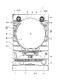
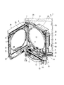
以下、図面を参照して本発明の好適な実施形態について説明する。先ず、図1及び図2を参照して実施形態に係るパチンコ機の全体構成について説明する。図1は、パチンコ機を示す正面図である。図2は、本体枠及び前面枠を開放した状態のパチンコ機を示す斜視図である。   Hereinafter, preferred embodiments of the present invention will be described with reference to the drawings. First, the overall configuration of the pachinko machine according to the embodiment will be described with reference to FIGS. 1 and 2. FIG. 1 is a front view showing a pachinko machine. FIG. 2 is a perspective view showing the pachinko machine with the main body frame and the front frame opened.

図1及び図2に示すように、パチンコ機1は、外枠2、本体枠3、遊技盤4、前面枠5等を備えて構成されている。外枠2は、上下左右の枠材によって縦長四角形の枠状に形成され、外枠2の前側下部には、本体枠3の下面を受ける下受板6を有している。外枠2の前面一側には、ヒンジ機構7によって本体枠3が前方に開閉可能に装着されている。また、本体枠3は、前枠体8、遊技盤装着枠9、及び機構装着枠10を合成樹脂材によって一体成形することで構成されている。本体枠3の前側に形成された前枠体8は、外枠2前側の下受板6を除く外郭形状に対応する大きさの矩形枠状に形成されている。   As shown in FIGS. 1 and 2, the pachinko machine 1 includes an outer frame 2, a main body frame 3, a game board 4, a front frame 5, and the like. The outer frame 2 is formed in a vertically rectangular frame shape by upper, lower, left and right frame members, and has a lower plate 6 that receives the lower surface of the main body frame 3 at the lower front side of the outer frame 2. A main body frame 3 is attached to the front side of the outer frame 2 by a hinge mechanism 7 so as to be opened and closed forward. The main body frame 3 is formed by integrally molding the front frame body 8, the game board mounting frame 9, and the mechanism mounting frame 10 with a synthetic resin material. The front frame 8 formed on the front side of the main body frame 3 is formed in a rectangular frame shape having a size corresponding to the outer shape excluding the support plate 6 on the front side of the outer frame 2.

前枠体8の後部に一体的に形成された遊技盤装着枠9には、遊技盤4が前方から着脱交換可能に装着されるようになっている。遊技盤4の盤面(前面)には、外レールと内レールとを備えた案内レール11が設けられ、該案内レール11の内側には、遊技領域12が区画形成されている。遊技盤装着枠9よりも下方に位置する前枠体8の前側下部の一側寄りには、スピーカ装着板13を介して低音用スピーカ14が装着されている。また、前枠体8前面の下部領域内の上側部分には、遊技盤4の発射通路に向けて遊技球を導く発射レール15が傾斜状に装着されている。一方、前枠体8前面の下部領域内の下側部分には、下前面部材16が装着されている。下前面部材16前面のほぼ中央には、下皿17が設けられ、片側寄りには操作ハンドル18が設けられている。   A game board 4 is attached to the game board mounting frame 9 integrally formed at the rear part of the front frame body 8 so as to be detachable and replaceable from the front. A guide rail 11 having an outer rail and an inner rail is provided on the board surface (front surface) of the game board 4, and a game area 12 is defined inside the guide rail 11. A low-frequency speaker 14 is mounted via a speaker mounting plate 13 near one side of the front lower portion of the front frame 8 positioned below the game board mounting frame 9. A launch rail 15 that guides a game ball toward the launch path of the game board 4 is attached to the upper portion in the lower region of the front surface of the front frame 8 in an inclined manner. On the other hand, a lower front member 16 is attached to a lower portion in the lower area of the front surface of the front frame body 8. A lower pan 17 is provided substantially at the center of the front surface of the lower front member 16, and an operation handle 18 is provided closer to one side.

本体枠3(前枠体8)のヒンジ機構7が設けられる側とは反対側となる開放側の後面には、外枠2に対して本体枠3を施錠する機能と、本体枠3に対して前面枠5を施錠する機能とを兼ね備えた施錠装置19が装着されている。施錠装置19は、外枠2に設けられた閉止具20に係脱可能に係合して本体枠3を閉鎖状態に施錠する上下複数の本体枠施錠フック21と、前面枠5の開放側の後面に設けられた閉止具22に係脱可能に係合して前面枠5を閉鎖状態に施錠する上下複数の扉施錠フック23とを備えている。そして、シリンダー錠24の鍵穴に鍵が挿入されて一方向に回動操作されることで、本体枠施錠フック21と外枠2の閉止具20との係合が解除されて本体枠3が解錠され、これとは逆方向に鍵が回動操作されることで、扉施錠フック23と前面枠5の閉止具22との係合が解除されて前面枠5が解錠されるようになっている。なお、シリンダー錠24の前端部は、パチンコ機1の前方から鍵を挿入して解錠操作が行えるように、前枠体8及び下前面部材16を貫通して下前面部材16の前面に露出して配置されている。   A function of locking the main body frame 3 with respect to the outer frame 2 is provided on the rear surface of the main body frame 3 (front frame body 8) opposite to the side where the hinge mechanism 7 is provided. A locking device 19 having a function of locking the front frame 5 is attached. The locking device 19 includes a plurality of upper and lower body frame locking hooks 21 that are detachably engaged with a closing tool 20 provided on the outer frame 2 to lock the main body frame 3 in a closed state, and an open side of the front frame 5. There are provided a plurality of upper and lower door locking hooks 23 that are detachably engaged with a closing tool 22 provided on the rear surface and lock the front frame 5 in a closed state. Then, the key is inserted into the key hole of the cylinder lock 24 and rotated in one direction, so that the engagement between the main body frame locking hook 21 and the closing tool 20 of the outer frame 2 is released, and the main body frame 3 is released. When the key is locked and the key is rotated in the opposite direction, the engagement between the door locking hook 23 and the closing tool 22 of the front frame 5 is released, and the front frame 5 is unlocked. ing. The front end of the cylinder lock 24 is exposed to the front surface of the lower front member 16 through the front frame body 8 and the lower front member 16 so that the unlocking operation can be performed by inserting a key from the front of the pachinko machine 1. Are arranged.

本体枠3前面の一側には、ヒンジ機構25によって前面枠5が前方に開閉可能に装着されている。前面枠5は、扉本体フレーム26、サイド装飾装置27、上皿28、音響電飾装置29を備えて構成されている。扉本体フレーム26は、プレス加工された金属製フレーム部材によって構成され、前枠体8の上端から下前面部材16の上縁に亘る部分を覆う大きさに形成されている。扉本体フレーム26のほぼ中央には、遊技盤4の遊技領域12を前方から透視可能なほぼ円形状の開口窓30が形成されている。また、扉本体フレーム26の後側には、開口窓30よりも大きい矩形枠状をなす窓枠31が設けられ、該窓枠31には、透明板32が装着されている。   A front frame 5 is attached to one side of the front surface of the main body frame 3 by a hinge mechanism 25 so as to be opened and closed forward. The front frame 5 includes a door body frame 26, a side decoration device 27, an upper plate 28, and an acoustic illumination device 29. The door main body frame 26 is formed of a pressed metal frame member, and is formed to have a size that covers a portion extending from the upper end of the front frame body 8 to the upper edge of the lower front member 16. A substantially circular opening window 30 through which the game area 12 of the game board 4 can be seen through from the front is formed at substantially the center of the door body frame 26. Further, a window frame 31 having a rectangular frame shape larger than the opening window 30 is provided on the rear side of the door body frame 26, and a transparent plate 32 is attached to the window frame 31.

扉本体フレーム26の前側には、開口窓30の周囲において、左右両側部にサイド装飾装置27が、下部に上皿28が、上部に音響電飾装置29が装着されている。サイド装飾装置27は、ランプ基板が内部に配置され且つ合成樹脂材によって形成されたサイド装飾体33を主体として構成されている。サイド装飾体33には、横方向に長いスリット状の開口孔が上下方向に複数配列されており、該開口孔には、ランプ基板に配置された光源に対応するレンズ34が組み込まれている。音響電飾装置29は、透明カバー体35、スピーカ36、スピーカカバー37、及びリフレクタ体(図示しない)等を備え、これらの構成部材が相互に組み付けられてユニット化されている。   On the front side of the door main body frame 26, around the opening window 30, side decoration devices 27 are mounted on the left and right sides, an upper plate 28 is mounted on the lower portion, and an acoustic decoration device 29 is mounted on the upper portion. The side decoration device 27 is mainly configured by a side decoration body 33 in which a lamp substrate is disposed and formed of a synthetic resin material. A plurality of slit-like opening holes that are long in the horizontal direction are arranged in the side decoration body 33 in the vertical direction, and a lens 34 corresponding to a light source disposed on the lamp substrate is incorporated in the opening hole. The acoustic illumination device 29 includes a transparent cover body 35, a speaker 36, a speaker cover 37, a reflector body (not shown), and the like, and these constituent members are assembled together to form a unit.

次に、遊技盤4に区画形成された遊技領域12内に設けられる各種構成部材について図3を参照して説明する。図3は、遊技盤を示す正面図である。   Next, various components provided in the game area 12 partitioned on the game board 4 will be described with reference to FIG. FIG. 3 is a front view showing the game board.

遊技領域12のほぼ中央には、本実施形態の要部をなす中央入賞装置40(可変入賞装置)が配設されている。中央入賞装置40の下方には、始動口スイッチ42(図5参照:始動検出手段)を内蔵した始動入賞口41が配置されている。始動入賞口41に打球が入賞すると、これを始動口スイッチ42が検出することで、中央入賞装置40を所定期間開放するようになっている。   A central winning device 40 (variable winning device), which is a main part of the present embodiment, is disposed substantially at the center of the game area 12. Below the central winning device 40, a start winning port 41 having a built-in start port switch 42 (see FIG. 5: start detecting means) is arranged. When a hitting ball is won at the start winning opening 41, the start opening switch 42 detects this to open the central winning apparatus 40 for a predetermined period.

始動入賞口41の下方には、横長長方形状の大入賞口61を開閉する開閉板62を有する大入賞口装置60が配設されている。大入賞口装置60は、大入賞口61(開閉板62)の開閉用駆動源となる大入賞口ソレノイド63と、大入賞口カウントスイッチ64(入賞検出手段)と(共に図5参照)を備えている。大入賞口装置60の下方となる遊技領域12の最下部には、遊技領域12を流下していずれの入賞口や入賞装置にも入賞しなかった遊技球が取り込まれるアウト口65が設けられている。また、遊技領域12には、上記した構成以外にも、サイドランプ66を内蔵したサイドランプ飾り67や、図示しない風車、障害釘等が設けられている。   Below the start winning opening 41, a large winning opening device 60 having an opening / closing plate 62 for opening and closing a horizontally long rectangular winning opening 61 is disposed. The big prize opening device 60 includes a big prize opening solenoid 63 as a driving source for opening and closing the big prize opening 61 (opening / closing plate 62) and a big prize opening count switch 64 (winning detection means) (both see FIG. 5). ing. At the bottom of the game area 12 below the big prize opening device 60, there is provided an out mouth 65 through which the game balls that have flown down the game area 12 and have not won any prize opening or winning apparatus are taken in. Yes. In addition to the above-described configuration, the game area 12 is provided with a side lamp decoration 67 incorporating a side lamp 66, a windmill (not shown), an obstacle nail, and the like.

遊技盤4に設けられる各種の入賞装置等によって実現される遊技について説明すると、パチンコ機1の裏面側に設けられる発射装置(図示しない)によって打ち出されて発射レール15及び案内レール11を通って遊技領域12に放出された遊技球は、遊技領域12を障害釘等に衝突しながらアウト口65に向かって流下する。遊技領域12を流下する遊技球が始動入賞口41に入賞して始動口スイッチ42によって検出されると、中央入賞装置40の後述する開閉片46が所定期間(例えば、0.3秒)開放され、中央入賞装置40に遊技球が入賞し得るようになっている。   The game realized by various winning devices provided on the game board 4 will be described. The game is launched by a launch device (not shown) provided on the back side of the pachinko machine 1 and passes through the launch rail 15 and the guide rail 11. The game ball released to the area 12 flows down toward the out port 65 while colliding with the obstacle nail or the like in the game area 12. When a game ball flowing down the game area 12 wins the start winning opening 41 and is detected by the start opening switch 42, an opening / closing piece 46 to be described later of the central winning device 40 is opened for a predetermined period (for example, 0.3 seconds). The game ball can win the central winning device 40.

そして、中央入賞装置40に遊技球が入賞して、その入賞球が中央入賞装置40内の後述する特定入賞領域スイッチ74(特定検出手段)によって検出されると、「大当り遊技状態(特定遊技状態)」となって、大入賞口装置60の開閉板62が手前側に倒れて大入賞口61を開放し、所定時間(例えば、30秒)、あるいは所定個数(例えば、9個)の入賞があるまで大入賞口61を開放した状態に維持する。その後、開閉板62の起立により大入賞口61が一旦閉じられ、再度、開閉板62が手前側に倒れることにより、大入賞口61が開放される開閉サイクル(ラウンド)を15回繰り返すようになっている(特定遊技状態発生手段)。なお、実施形態中では、無条件に15ラウンドを継続させる構成としているが、上記した構成に限定しない。例えば、大入賞口装置60内にラウンド継続スイッチを設け、該ラウンド継続スイッチで遊技球を検出したことを条件としてラウンドを継続するようにしてもよい。また、大入賞口61に少なくとも1個以上の入賞があることを条件としてラウンドを継続するようにしてもよい。また、開閉サイクル(ラウンド)も15回に限定しない(例えば、2回や7回等の開閉サイクルであってもよい)。また、始動入賞口41への入賞(始動口スイッチ42による遊技球の検出)に基づいて乱数抽出を行い、該乱数の抽出値から当り(小当りも含む)外れを決定し、大当りの場合には、そのまま大入賞口61を開放制御し、小当りの場合に開閉片46を開放制御するようにしてもよい。   Then, when a game ball wins the central winning device 40 and the winning ball is detected by a specific winning area switch 74 (specific detecting means) to be described later in the central winning device 40, the “big hit gaming state (specific gaming state) ) ", The open / close plate 62 of the grand prize opening device 60 falls to the front side to open the grand prize winning opening 61, and a predetermined time (for example, 30 seconds) or a predetermined number (for example, nine) of prizes are received. The grand prize winning opening 61 is kept open until it is. After that, the winning prize opening 61 is temporarily closed by the standing of the opening / closing plate 62, and the opening / closing cycle (round) in which the winning prize opening 61 is opened by repeating the opening / closing plate 62 again is repeated 15 times. (Specific gaming state generating means). In addition, in embodiment, although it is set as the structure which continues 15 rounds unconditionally, it is not limited to an above-described structure. For example, a round continuation switch may be provided in the special prize opening device 60, and the round may be continued on condition that a game ball is detected by the round continuation switch. Alternatively, the round may be continued on condition that there is at least one winning in the big winning opening 61. Further, the open / close cycle (round) is not limited to 15 times (for example, the open / close cycle may be 2 times or 7 times). Also, random number extraction is performed based on winning at the start winning opening 41 (detection of a game ball by the start opening switch 42), and the winning (including small hit) is determined from the extracted value of the random number, and in the case of big hit May open the large winning opening 61 as it is, and control the opening of the open / close piece 46 in the case of a small hit.

遊技領域12のほぼ中央に配置される中央入賞装置40は、図3に示すように、当該中央入賞装置40を遊技盤4の表面(遊技領域12)に取り付けるための取付基板43を有し、該取付基板43には、上部入賞空間44(入賞空間)と下部入賞空間45(入賞空間)が形成されている。上部入賞空間44には、左右一対の開閉片46が回転可能に設けられている。開閉片46は、それぞれ周知のリンク機構を介して開閉片ソレノイド47(図5参照)が連結され、該開閉片ソレノイド47がONしたときに、上部入賞空間44を開放する方向、即ち遊技球の進入口46a(図4参照)を形成する方向に回転する一方、開閉片ソレノイド47がOFFしたときに、上部入賞空間44を閉鎖する方向に回転するようになっている。左右の開閉片46の各近接部分となる上部入賞空間44内には、それぞれ上部入賞空間44に入賞した遊技球(進入口46aから進入した遊技球)を検出する開閉片カウントスイッチ48(図5参照:進入検出手段)が設けられ、上部入賞空間44の底壁部分には、入賞球を後方に向かって転動させる上部転動板49(転動装置)が設けられている。なお、開閉片カウントスイッチ48で検出された入賞球は、上部転動板49を流下した後に図示しない球落下口から下部入賞空間45に送り込まれるようになっている。   As shown in FIG. 3, the central prize-winning device 40 disposed almost in the center of the game area 12 has an attachment board 43 for attaching the central prize-winning device 40 to the surface of the game board 4 (game area 12). An upper winning space 44 (winning space) and a lower winning space 45 (winning space) are formed on the mounting substrate 43. In the upper winning space 44, a pair of left and right opening / closing pieces 46 are rotatably provided. Each open / close piece 46 is connected to an open / close piece solenoid 47 (see FIG. 5) via a well-known link mechanism. When the open / close piece solenoid 47 is turned on, the upper winning space 44 is opened, that is, the game ball is opened. While rotating in the direction of forming the entrance 46a (see FIG. 4), when the open / close piece solenoid 47 is turned OFF, the upper winning space 44 is closed. An open / close piece count switch 48 (FIG. 5) for detecting a game ball (game ball that has entered from the entrance 46a) winning in the upper prize space 44 is placed in the upper prize space 44, which is adjacent to the left and right open / close pieces 46. Reference: entry detecting means) is provided, and an upper rolling plate 49 (rolling device) for rolling the winning ball backward is provided on the bottom wall portion of the upper winning space 44. The winning ball detected by the open / close piece count switch 48 flows down the upper rolling plate 49 and then is sent to the lower winning space 45 from a ball drop opening (not shown).

一方、下部入賞空間45の後壁部分には、図4に示すように、液晶表示器50(表示器)が設けられている。液晶表示器50は、下部入賞空間45後壁部分のほぼ全体に表示画面が臨設されて演出表示を行うようになっている。液晶表示器50の前方には、可動通路部材51(転動装置)が設けられている。可動通路部材51は、スライド用モータ52(図5参照:スライド移動機構)の駆動に基づいて左右方向にスライド移動可能に設けられている。具体的には、スライド用モータ52の回転駆動により、可動通路部材51の下端部分と係合して設けられた搬送ベルト(図示しない:スライド移動機構)が正逆方向に回転することで、可動通路部材51の左右方向へのスライド移動が行われるようになっている。但し、開閉片カウントスイッチ48による遊技球の検出がない状態、即ち、中央入賞装置40内への遊技球の入賞がない状態では、可動通路部材51は、液晶表示器50の右側方に設けられた収容領域76内に収容された状態となる。そして、始動入賞口41への入賞に伴う開閉片46の開放によって中央入賞装置40内に遊技球が入賞すると(開閉片カウントスイッチ48によって遊技球が検出されると)、これに基づいて、収容領域76に収容された可動通路部材51は、左方向(液晶表示器50の前側方向)に向ってスライド移動し、液晶表示器50のほぼ中央位置まで移動した後に所定期間停止し、その後、右方向へのスライド移動によって再度収容領域76内に収容されるようになっている。なお、収容領域76は、遊技領域12(遊技盤4)の裏面空間に設けられ、当該遊技領域12には、収容領域76に収容された可動通路部材51(厳密には、後述する球受回動部材55の部分)を前方から視認可能にする円形状の視認穴77が穿設されている。また、当該視認穴77の前方には、遊技領域12の表面と面一となるように透明な板部材77aが取り付けられており、これによって視認穴77の前方部分でも遊技球の流下を可能にしている。   On the other hand, as shown in FIG. 4, a liquid crystal display 50 (display) is provided on the rear wall portion of the lower winning space 45. In the liquid crystal display 50, a display screen is provided on almost the entire rear wall portion of the lower prize winning space 45 to perform effect display. A movable passage member 51 (rolling device) is provided in front of the liquid crystal display 50. The movable passage member 51 is provided so as to be slidable in the left-right direction based on the drive of a slide motor 52 (see FIG. 5: slide movement mechanism). Specifically, when the slide motor 52 is driven to rotate, a transport belt (not shown: a slide movement mechanism) provided in engagement with the lower end portion of the movable passage member 51 rotates in the forward and reverse directions, thereby moving the slide belt. The passage member 51 is slid in the left-right direction. However, the movable passage member 51 is provided on the right side of the liquid crystal display 50 in a state where the game ball is not detected by the open / close piece count switch 48, that is, in a state where there is no game ball winning in the central winning device 40. It will be in the state accommodated in the accommodation area | region 76. Then, when a game ball is won in the central winning device 40 by opening the opening / closing piece 46 accompanying the winning at the start winning opening 41 (when the game ball is detected by the opening / closing piece count switch 48), accommodation is performed based on this. The movable passage member 51 accommodated in the region 76 slides leftward (toward the front side of the liquid crystal display 50) and stops for a predetermined period after moving to approximately the center position of the liquid crystal display 50, and then to the right It is accommodated again in the accommodation area 76 by sliding movement in the direction. The accommodation area 76 is provided in the back space of the game area 12 (game board 4), and the game area 12 includes a movable passage member 51 (strictly speaking, a ball reception described later) accommodated in the accommodation area 76. A circular viewing hole 77 is formed to make the moving member 55 portion visible) from the front. In addition, a transparent plate member 77 a is attached in front of the visual recognition hole 77 so as to be flush with the surface of the game area 12, thereby allowing the game ball to flow down even in the front part of the visual recognition hole 77. ing.

可動通路部材51の上側部分には、上部転動板49の球落下口から送り込まれた遊技球を受け入れ、該遊技球を回転させながら下方の排出口54から排出するクルーン部53が設けられている。即ち、クルーン部53の上面開口53aが可動通路部材51の球入口となっている。クルーン部53は、透明な材料によって形成されており、クルーン部53内での遊技球の球流れが視認可能となっている。クルーン部53の下方には、回転用モータ56(図5参照)の駆動に基づいて常時、時計方向に回動する円盤形状の球受回動部材55が設けられている。球受回動部材55には、周方向に一定間隔を置いて8個の球受凹部57が形成されている。8個の球受凹部57は、それぞれ1個の遊技球を受け入れ可能な形状に形成されており、クルーン部53の排出口54から排出された遊技球が、球受回動部材55の上端側に設けられた球受入口58を通っていずれかの球受凹部57に受け入れられるようになっている。なお、球受入口58には、該球受入口58を通過した遊技球、言い換えれば球受凹部57に遊技球が入ったことを検出するための球受入スイッチ59(通路内検出手段)が設けられている。また、球受回動部材55の下端側には、球受回動部材55の回動動作に伴って球受凹部57内の遊技球を下方に排出する球排出口70が設けられており、球受回動部材55の回動中心となる前面部分には、演出ランプ71が設けられている。   The upper portion of the movable passage member 51 is provided with a cruising portion 53 that receives a game ball sent from the ball drop port of the upper rolling plate 49 and discharges it from the lower discharge port 54 while rotating the game ball. Yes. That is, the upper surface opening 53 a of the cruising portion 53 serves as a ball inlet of the movable passage member 51. The cruising part 53 is formed of a transparent material, and the sphere flow of the game ball in the cruising part 53 is visible. A disk-shaped ball receiving and rotating member 55 that always rotates clockwise based on the driving of the rotation motor 56 (see FIG. 5) is provided below the cruising portion 53. The ball receiving and rotating member 55 is formed with eight ball receiving recesses 57 at regular intervals in the circumferential direction. Each of the eight ball receiving recesses 57 is formed in a shape capable of receiving one game ball, and the game ball discharged from the discharge port 54 of the clune portion 53 is on the upper end side of the ball receiving rotation member 55. Is received by any one of the ball receiving recesses 57 through the ball receiving port 58 provided in. The ball receiving port 58 is provided with a ball receiving switch 59 (in-passage detection means) for detecting that a game ball that has passed through the ball receiving port 58, in other words, that a game ball has entered the ball receiving recess 57 is provided. It has been. In addition, a ball discharge port 70 is provided at the lower end side of the ball receiving / turning member 55 to discharge the game ball in the ball receiving recess 57 downward as the ball receiving / turning member 55 rotates. An effect lamp 71 is provided on the front surface portion that is the rotation center of the ball receiving and rotating member 55.

球受回動部材55の下方位置となる下部入賞空間45の下端部には、特定入賞領域72と、通常入賞領域73とが設けられている。特定入賞領域72及び通常入賞領域73は、それぞれ液晶表示器50の下辺右側部分に配され、該下辺右側部分のほぼ中央部分が特定入賞領域72となり、残りの部分が通常入賞領域73となっている。特定入賞領域72には、該特定入賞領域72に入った遊技球を検出するための特定入賞領域スイッチ74(図5参照)が設けられ、通常入賞領域73には、該通常入賞領域73に入った遊技球を検出するための通常入賞領域スイッチ75(図5参照:通常検出手段)が設けられている。そして、球排出口70から排出された遊技球が特定入賞領域72に入り特定入賞領域スイッチ74によって検出されると、当該検出に基づいて大当り遊技状態が発生される。なお、開閉片カウントスイッチ48による遊技球の検出に基づいて、払出装置103(図5参照)から所定数の賞球が払い出される。   A specific winning area 72 and a normal winning area 73 are provided at the lower end of the lower winning space 45 that is located below the ball receiving and rotating member 55. The specific winning area 72 and the normal winning area 73 are respectively arranged on the right side of the lower side of the liquid crystal display 50, the central part of the right side of the lower side becomes the specific winning area 72, and the remaining part becomes the normal winning area 73. Yes. The specific winning area 72 is provided with a specific winning area switch 74 (see FIG. 5) for detecting a game ball that has entered the specific winning area 72, and the normal winning area 73 is included in the normal winning area 73. A normal winning area switch 75 (see FIG. 5: normal detecting means) for detecting a game ball is provided. When the game ball discharged from the ball discharge port 70 enters the specific winning area 72 and is detected by the specific winning area switch 74, a big hit gaming state is generated based on the detection. A predetermined number of prize balls are paid out from the payout device 103 (see FIG. 5) based on the detection of the game ball by the open / close piece count switch 48.

次に、パチンコ機1の裏面側に設けられる主制御基板101及び周辺制御基板111について図5を参照して説明する。図5は、主制御基板101及び周辺制御基板111を示すブロック図である。   Next, the main control board 101 and the peripheral control board 111 provided on the back side of the pachinko machine 1 will be described with reference to FIG. FIG. 5 is a block diagram showing the main control board 101 and the peripheral control board 111.

図5に示すように、主制御基板101は、中央演算装置としてのCPU101a、読み出し専用メモリとしてのROM101b、読み書き可能メモリとしてのRAM101cを備えている。CPU101aは、ROM101bに格納されている制御プログラムを実行することによりパチンコ機1で行われる各種遊技を制御したり、周辺制御基板111や払出制御基板102に出力するコマンド信号を作成したりする。RAM101cには、主制御基板101で実行される種々の処理において生成される各種データや入力信号等の情報が一時的に記憶される。主制御基板101には、大入賞口カウントスイッチ64、始動口スイッチ42、開閉片カウントスイッチ48、特定入賞領域スイッチ74、及び通常入賞領域スイッチ75からの検出信号が入力される。一方、主制御基板101は、大入賞口ソレノイド63、開閉片ソレノイド47、スライド用モータ52、及び回転用モータ56へ駆動信号を出力する。また、主制御基板101は、払出制御基板102にコマンド信号を出力する。そして、払出制御基板102は、主制御基板101から入力したコマンド信号を処理して、払出装置103(払出モータ)に駆動信号を出力する。これにより、払出装置103は、駆動信号に従って遊技球を払い出す。   As shown in FIG. 5, the main control board 101 includes a CPU 101a as a central processing unit, a ROM 101b as a read-only memory, and a RAM 101c as a readable / writable memory. The CPU 101a controls various games performed in the pachinko machine 1 by executing a control program stored in the ROM 101b, and creates a command signal to be output to the peripheral control board 111 and the payout control board 102. The RAM 101c temporarily stores various data generated in various processes executed by the main control board 101 and information such as input signals. The main control board 101 is supplied with detection signals from the big winning opening count switch 64, the start opening switch 42, the open / close piece count switch 48, the specific winning area switch 74, and the normal winning area switch 75. On the other hand, the main control board 101 outputs drive signals to the special winning opening solenoid 63, the open / close piece solenoid 47, the slide motor 52, and the rotation motor 56. Further, the main control board 101 outputs a command signal to the payout control board 102. The payout control board 102 processes the command signal input from the main control board 101 and outputs a drive signal to the payout device 103 (payout motor). Thereby, the payout device 103 pays out the game ball according to the drive signal.

周辺制御基板111は、CPU111a、ROM111b、RAM111cを備えている。CPU111aは、ROM111bに格納されている制御プログラムに従ってコマンド信号を処理する。RAM111cには、周辺制御基板111で実行される種々の処理において生成される各種データや入出力信号等の情報が一時的に記憶される。主制御基板101には、主制御基板101からのコマンド信号が入力されると共に、球受入スイッチ59からの検出信号が入力される。そして、周辺制御基板111は、主制御基板101からのコマンド信号に基づいてスピーカ36及びサイドランプ67を制御すると共に、球受入スイッチ59からの検出信号に基づいて演出ランプ71を点灯制御する。また、周辺制御基板111は、液晶制御基板104にコマンド信号を出力する。そして、液晶制御基板104は、周辺制御基板111から入力したコマンド信号を処理して、液晶表示器50に駆動信号を出力する(演出表示制御手段)。   The peripheral control board 111 includes a CPU 111a, a ROM 111b, and a RAM 111c. The CPU 111a processes the command signal according to the control program stored in the ROM 111b. The RAM 111c temporarily stores information such as various data and input / output signals generated in various processes executed by the peripheral control board 111. A command signal from the main control board 101 and a detection signal from the ball receiving switch 59 are input to the main control board 101. Then, the peripheral control board 111 controls the speaker 36 and the side lamp 67 based on the command signal from the main control board 101 and controls the lighting of the effect lamp 71 based on the detection signal from the ball receiving switch 59. In addition, the peripheral control board 111 outputs a command signal to the liquid crystal control board 104. Then, the liquid crystal control board 104 processes the command signal input from the peripheral control board 111 and outputs a drive signal to the liquid crystal display 50 (effect display control means).

次に、中央入賞装置40に入賞した遊技球の流れ、及びこれに伴う中央入賞装置40の各種構成部材の動作について、図6乃至図10を参照して説明する。図6は、通常入賞領域73に遊技球が入賞する場合の中央入賞装置40の各種構成部材の動作を示すタイムチャートである。図7は、通常入賞領域73に遊技球が入賞する場合の可動通路部材51の動作を示す正面図である。図8は、特定入賞領域72に遊技球が入賞する場合の中央入賞装置40の各種構成部材の動作を示すタイムチャートである。図9は、特定入賞領域72に遊技球が入賞する場合の可動通路部材51の動作を示す正面図である。図10は、可動通路部材51の動作に伴う液晶表示器50での演出を示す説明図である。   Next, the flow of game balls won in the central winning device 40 and the operation of various components of the central winning device 40 associated therewith will be described with reference to FIGS. FIG. 6 is a time chart showing the operation of various components of the central winning device 40 when a game ball wins in the normal winning area 73. FIG. 7 is a front view showing the operation of the movable passage member 51 when a game ball wins the normal winning area 73. FIG. 8 is a time chart showing the operation of various components of the central winning device 40 when a game ball wins the specific winning area 72. FIG. 9 is a front view showing the operation of the movable passage member 51 when a game ball wins the specific winning area 72. FIG. 10 is an explanatory diagram showing effects on the liquid crystal display 50 accompanying the operation of the movable passage member 51.

先ず、通常入賞領域73に遊技球が入賞する場合の中央入賞装置40の各種構成部材の動作について説明する。図6において、始動入賞口41への遊技球の入賞に基づいて始動口スイッチ42がONすると、その0.2秒後に中央入賞装置40の開閉片46が0.3秒間開放される。そして、当該開閉片46の開放に伴って上部入賞空間44内に遊技球が入賞すると、該遊技球は、開閉片カウントスイッチ48によって検出される。なお、このとき、開閉片46の開放開始時点から0.5秒が経過するまでの期間内で、開閉片カウントスイッチ48による遊技球の検出がない場合、即ち、開閉片46が開放されたにも拘わらず上部入賞空間44内に遊技球が入賞しなかった場合、この時点までに次位の始動入賞口41への入賞(始動口スイッチ42のON)が検出されていると、最初の開閉片46の開放開始から0.5秒が経過した時点で、次位の始動口スイッチ42のONに基づく開閉片46の開放が開始される。   First, the operation of various components of the central winning device 40 when a game ball wins the normal winning area 73 will be described. In FIG. 6, when the start opening switch 42 is turned on based on the winning of the game ball in the start winning opening 41, the opening / closing piece 46 of the central winning apparatus 40 is opened for 0.3 seconds after 0.2 seconds. When a game ball wins in the upper winning space 44 as the opening / closing piece 46 is opened, the game ball is detected by the opening / closing piece count switch 48. At this time, if no game ball is detected by the open / close piece count switch 48 within a period from when the open / close piece 46 starts to open until 0.5 seconds elapses, that is, the open / close piece 46 is opened. Nevertheless, if the game ball has not won in the upper winning space 44, the first opening / closing will be performed if the winning to the next starting winning port 41 (ON of the starting port switch 42) is detected by this time. When 0.5 second has elapsed since the opening of the piece 46 has started, the opening of the opening / closing piece 46 based on the ON of the next starter switch 42 is started.

一方、開閉片46の開放開始時点から0.5秒が経過するまでの期間内で、開閉片カウントスイッチ48による遊技球の検出がある場合(開閉片46の開放に伴って上部入賞空間44内に遊技球が入賞した場合)、開閉片46の開放開始から0.5秒が経過した時点で、スライド用モータ52がONされることで、可動通路部材51が収容領域76(第二の位置)から左方向(液晶表示器50の前側方向)に向って一定速度でスライド移動を開始する。このような可動通路部材51の左方向へのスライド移動(スライド用モータ52のON)は、0.5秒間行われ、この時点で、可動通路部材51は、液晶表示器50のほぼ中央位置(第一の位置)まで移動して2.0秒間停止する。また、液晶表示器50の演出表示は、可動通路部材51がスライド移動を開始するまでは、通常時の演出画像(図示しない)が表示され、可動通路部材51がスライド移動を開始すると同時に、スライド移動時の演出画像(図示しないが、例えば、可動通路部材51のスライド移動をその背面側で装飾的に演出する画像)に切り替えられる。   On the other hand, when a game ball is detected by the open / close piece count switch 48 within a period from when the open / close piece 46 starts to open until 0.5 seconds elapses (in the upper winning space 44 as the open / close piece 46 opens). When the game ball wins the game), when 0.5 seconds have elapsed since the opening of the opening / closing piece 46, the sliding motor 52 is turned on, so that the movable passage member 51 is placed in the accommodation region 76 (second position). ) From the left to the left (front side of the liquid crystal display 50). Such sliding movement of the movable passage member 51 in the left direction (ON of the sliding motor 52) is performed for 0.5 seconds. At this time, the movable passage member 51 is positioned at a substantially central position of the liquid crystal display 50 ( Move to the first position) and stop for 2.0 seconds. Further, the effect display on the liquid crystal display 50 displays a normal effect image (not shown) until the movable passage member 51 starts sliding movement, and at the same time the movable passage member 51 starts sliding movement, the slide is performed. An effect image at the time of movement (not shown, for example, an image that effects a decorative movement of the movable passage member 51 on the back side thereof).

これに対して、開閉片カウントスイッチ48によって検出された遊技球は、上部転動板49を転動して上部入賞空間44から下部入賞空間45に送り込まれ、液晶表示器50のほぼ中央位置で停止した可動通路部材51のクルーン部53に入る。その後、遊技球は、クルーン部53内を螺旋方向に回転して排出口54から排出された後、球受入口58を通って球受回動部材55のいずれかの球受凹部57に受け入れられる。なお、このとき、球受凹部57が球受入口58と一致しない球受回動部材55の回動位置となる場合には、球受入口58の部分で遊技球が停留された状態となり、球受回動部材55の回動によって球受凹部57が球受入口58と一致した時点で、遊技球は、球受入口58を通過して(球受凹部57に入って)球受入スイッチ59で検出される。但し、球受回動部材55の回動動作は、中央入賞装置40の各種構成部材の動作や各種の球検出スイッチのON/OFFに関わらず、電源投入時点から一定の回転速度で継続的に行われるものである。   On the other hand, the game ball detected by the open / close piece count switch 48 rolls on the upper rolling plate 49 and is sent from the upper winning space 44 to the lower winning space 45, and at a substantially central position of the liquid crystal display 50. The crushed portion 53 of the stopped movable passage member 51 is entered. Thereafter, the game ball rotates in the spiral direction in the clune portion 53 and is discharged from the discharge port 54, and then is received by the ball receiving recess 57 of the ball receiving rotation member 55 through the ball receiving port 58. . At this time, when the ball receiving recess 57 is at the rotation position of the ball receiving rotation member 55 that does not coincide with the ball receiving port 58, the game ball is stopped at the portion of the ball receiving port 58, and the ball When the ball receiving recess 57 coincides with the ball receiving port 58 by the rotation of the receiving rotation member 55, the game ball passes through the ball receiving port 58 (enters the ball receiving recess 57) with the ball receiving switch 59. Detected. However, the rotation operation of the ball receiving and rotating member 55 is continuously performed at a constant rotational speed from the time of turning on the power regardless of the operation of various components of the central winning device 40 and ON / OFF of various ball detection switches. Is to be done.

また、上記したように球受入スイッチ59によって遊技球が検出されると、これと同時に、液晶表示器50の演出表示は、予告演出用の画像に切り替えられる。この予告演出用の画像は、図10(A),(C)に示す2種類があり、図10(A)の予告演出画像では、球受回動部材55の回動中心に配置された演出ランプ71を射撃の的としてピストルを向けたキャラクタ80が、可動通路部材51の左側方となる液晶表示器50の表示領域に表示される。一方、図10(C)の予告演出画像では、球受回動部材55の回動中心に配置された演出ランプ71を射撃の的としてバズーカ砲を構えたキャラクタ81が、可動通路部材51の左側方となる液晶表示器50の表示領域に表示される。このような2種類の予告演出画像の選択は、周辺制御基板111のCPU111aによって行われる。   Further, when a game ball is detected by the ball acceptance switch 59 as described above, the effect display on the liquid crystal display 50 is switched to the image for the notice effect at the same time. There are two types of images for the notice effect as shown in FIGS. 10A and 10C. In the notice effect image shown in FIG. 10A, an effect arranged at the center of rotation of the ball receiving rotation member 55. A character 80 with a pistol directed at the target of shooting the lamp 71 is displayed in the display area of the liquid crystal display 50 on the left side of the movable passage member 51. On the other hand, in the notice effect image of FIG. 10C, the character 81 holding the bazooka gun with the effect lamp 71 arranged at the rotation center of the ball receiving rotation member 55 as the target of shooting is located on the left side of the movable passage member 51. Is displayed in the display area of the liquid crystal display 50. Selection of such two types of notice effect images is performed by the CPU 111a of the peripheral control board 111.

具体的には、可動通路部材51のスライド移動開始時点を基準とした球受入スイッチ59による遊技球の検出タイミングから、球受凹部57に入った遊技球が特定入賞領域72に入賞するか否かを周辺制御基板111のCPU111aが予測する。そして、周辺制御基板111のCPU111aが特定入賞領域72に入賞しないと予測したときには、的を射ぬくことが困難であることを遊技者に暗示するキャラクタ(図10(A)のピストルを向けたキャラクタ80)を予告演出画像として表示する一方、特定入賞領域72に入賞すると予測したときには、的を射ぬくことが容易であることを遊技者に暗示するキャラクタ(図10(C)のバズーカ砲を構えたキャラクタ81)を予告演出画像として表示する(特定入賞予測手段)。但し、遊技球が球受入スイッチ59によって検出されてから、当該遊技球が球排出口70から排出されるまでの時間には若干のばらつきが生じるため、必ずしも予告演出画像が特定入賞領域72への入賞の有無を遊技者に事前報知するものとはなっていない。また、射撃の的となる球受回動部材55中心の演出ランプ71は、通常状態で消灯状態が継続される。   Specifically, whether or not the game ball entering the ball receiving recess 57 wins the specific winning area 72 based on the detection timing of the game ball by the ball receiving switch 59 with the slide movement start time of the movable passage member 51 as a reference. Is predicted by the CPU 111a of the peripheral control board 111. Then, when the CPU 111a of the peripheral control board 111 predicts that the specific winning area 72 will not win, a character (a character pointing a pistol in FIG. 10A) implying the player that it is difficult to hit the target. 80) is displayed as a notice effect image, and when it is predicted that a special winning area 72 will be won, a character (a bazooka gun of FIG. 10 (C)) is provided to imply that it is easy to hit the target. Character 81) is displayed as a notice effect image (specific winning prediction means). However, there is a slight variation in the time from when a game ball is detected by the ball acceptance switch 59 until the game ball is discharged from the ball discharge port 70, so that the notice effect image is not necessarily displayed on the specific winning area 72. The player is not informed in advance of whether or not a prize has been won. In addition, the effect lamp 71 at the center of the ball receiving and rotating member 55 that is the target of shooting continues to be turned off in the normal state.

その後、液晶表示器50のほぼ中央位置で2.0秒間停止した可動通路部材51は、スライド用モータ52が再度ONされることで(但し、このときは、前述したスライド用モータ52の回転方向とは逆方向に回転)、右方向(収容領域76の方向)に向って一定速度でスライド移動を開始する。そして、図7に示すように、球受回動部材55の回動によって、遊技球を受け入れた球受凹部57が球排出口70と一致すると、球受凹部57内の遊技球は、球排出口70から通常入賞領域73に送り込まれ、通常入賞領域スイッチ75がONする。これにより、中央入賞装置40に入賞した遊技球は、大当り遊技状態の発生を伴わない通常の入賞球として処理される。   After that, the movable passage member 51 stopped for approximately 2.0 seconds at the substantially central position of the liquid crystal display 50 is turned on again by the slide motor 52 (however, in this case, the rotation direction of the slide motor 52 described above) The slide movement is started at a constant speed in the right direction (the direction of the accommodation area 76). Then, as shown in FIG. 7, when the ball receiving recess 57 receiving the game ball coincides with the ball discharge port 70 by the rotation of the ball receiving rotation member 55, the game ball in the ball receiving recess 57 is It is sent from the exit 70 to the normal winning area 73, and the normal winning area switch 75 is turned ON. Thereby, the game ball won in the central winning device 40 is processed as a normal winning ball without generating the big hit gaming state.

ところで、球受凹部57内の遊技球が特定入賞領域72に送り込まれるか否か、言い換えれば大当り遊技状態が発生するか否かは、可動通路部材51の右方向へのスライド移動時における遊技球の球排出口70からの排出タイミングによって決定される(受入切替手段)。遊技球の球排出口70からの排出タイミングが、可動通路部材51の右方向へのスライド開始時点から0.8秒が経過するまでの期間a内となる場合、遊技球は通常入賞領域73に送り込まれる。遊技球の球排出口70からの排出タイミングが、上記期間aの終了時点から0.4秒が経過するまでの期間b内となる場合、遊技球は特定入賞領域72に送り込まれる。遊技球の球排出口70からの排出タイミングが、上記期間bの終了時点から0.8秒が経過するまでの期間c内となる場合、遊技球は通常入賞領域73に送り込まれる。   By the way, whether or not the game ball in the ball receiving recess 57 is sent to the specific winning area 72, in other words, whether or not the big hit game state occurs, is determined when the movable path member 51 slides to the right. Determined by the discharge timing from the ball discharge port 70 (acceptance switching means). When the discharge timing of the game ball from the ball discharge port 70 is within a period a until 0.8 seconds elapses from the time when the movable passage member 51 starts to slide in the right direction, the game ball enters the normal winning area 73. It is sent. When the discharge timing of the game ball from the ball discharge port 70 is within the period b until 0.4 seconds elapse from the end of the period a, the game ball is sent to the specific winning area 72. When the discharge timing of the game ball from the ball discharge port 70 is within the period c from the end of the period b until 0.8 seconds elapses, the game ball is sent to the normal winning area 73.

また、このように通常入賞領域スイッチ75によって遊技球が検出されると、これと同時に、液晶表示器50の演出表示は、結果演出用の画像に切り替えられる。このときの結果演出画像としては、図10(B)に示すように、キャラクタ80が発射した弾が的から外れる画像82と、これを示す「スカッ」の文字83とが表示される。なお、球受入スイッチ59によって遊技球が検出された時点で、図10(C)に示した予告演出画像(バズーカ砲を構えたキャラクタ81)が表示され、その後、球受凹部57内の遊技球が通常入賞領域73に送り込まれた場合には、通常入賞領域スイッチ75によって遊技球が検出された時点で、キャラクタ81が発射したバズーカ弾が的から外れる画像と、これを示す「スカッ」の文字83とが表示される。また、このとき、射撃の的となる球受回動部材55中心の演出ランプ71は、弾が的から外れたことを示すように消灯状態のままである。   In addition, when a game ball is detected by the normal winning area switch 75 as described above, at the same time, the effect display on the liquid crystal display 50 is switched to a result effect image. As a result effect image at this time, as shown in FIG. 10 (B), an image 82 in which the bullet fired by the character 80 deviates from the target and a character 83 of “ska” indicating this are displayed. When a game ball is detected by the ball receiving switch 59, a notice effect image (a character 81 with a bazooka gun) shown in FIG. 10C is displayed, and then the game ball in the ball receiving recess 57 is displayed. When sent to the normal winning area 73, when a game ball is detected by the normal winning area switch 75, an image in which the bazooka bullet fired by the character 81 is out of the target, and a character 83 of "Suka" indicating this is displayed. Is displayed. At this time, the effect lamp 71 at the center of the ball receiving and rotating member 55 that is the target of shooting remains off so as to indicate that the bullet has been removed from the target.

その後は、可動通路部材51の右方向(収容領域76の方向)へのスライド移動が継続して行われ、右方向へのスライド移動を開始してから2.0秒後に、可動通路部材51は、収容領域76内に収容されて停止する。また、液晶表示器50の演出表示は、通常入賞領域73への入賞を示す結果演出画像が所定時間表示された後、通常時の演出画像に戻る。なお、可動通路部材51のスライド移動の速度は、上記したように左方向への移動速度と右方向への移動速度とで異なって設定されている。即ち、クルーン部53での遊技球の受け入れ前となる準備段階では、0.5秒という短い時間(速い速度)で可動通路部材51がスライド移動されるのに対して、クルーン部53での遊技球の受け入れが終了して球受凹部57内の遊技球を特定入賞領域72に送り込むか否かの興趣を高める演出段階では、2.0秒という長い時間(遅い速度)で可動通路部材51がスライド移動される。   Thereafter, the sliding movement of the movable passage member 51 in the right direction (in the direction of the accommodation region 76) is continuously performed, and 2.0 seconds after the sliding movement in the right direction is started, the movable passage member 51 Then, it is accommodated in the accommodation area 76 and stopped. The effect display on the liquid crystal display 50 returns to the effect image at the normal time after the result effect image indicating the winning in the normal winning area 73 is displayed for a predetermined time. Note that the sliding speed of the movable passage member 51 is set differently between the moving speed in the left direction and the moving speed in the right direction as described above. That is, in the preparatory stage before accepting the game ball in the cruising portion 53, the movable passage member 51 is slid and moved in a short time (fast speed) of 0.5 seconds, while the game in the cruising portion 53 is performed. At the stage of enhancing the interest of whether or not to accept the ball and sending the game ball in the ball receiving recess 57 to the specific winning area 72, the movable passage member 51 is moved in a long time (slow speed) of 2.0 seconds. The slide is moved.

次に、特定入賞領域72に遊技球が入賞する場合の中央入賞装置40の各種構成部材の動作について説明する。図8において、始動入賞口41への遊技球の入賞に基づいて始動口スイッチ42がONすると、その0.2秒後に中央入賞装置40の開閉片46が0.3秒間開放される。そして、当該開閉片46の開放に伴って上部入賞空間44内に遊技球が入賞すると、該遊技球は、開閉片カウントスイッチ48によって検出される。その後は、図6に示したタイムチャートと同様に、開閉片46の開放開始から0.5秒が経過した時点で、スライド用モータ52がONされることで、可動通路部材51が収容領域76から左方向(液晶表示器50の前側方向)に向って一定速度で0.5秒間スライド移動され、液晶表示器50のほぼ中央位置まで移動して2.0秒間停止する。また、液晶表示器50の演出表示も同様に、可動通路部材51がスライド移動を開始すると同時に、通常時の演出画像からスライド移動時の演出画像に切り替えられる。   Next, operations of various components of the central winning device 40 when a game ball wins in the specific winning area 72 will be described. In FIG. 8, when the start opening switch 42 is turned on based on the winning of a game ball in the start winning opening 41, the opening / closing piece 46 of the central winning apparatus 40 is opened for 0.3 seconds after 0.2 seconds. When a game ball wins in the upper winning space 44 as the opening / closing piece 46 is opened, the game ball is detected by the opening / closing piece count switch 48. Thereafter, similarly to the time chart shown in FIG. 6, when 0.5 second has elapsed from the start of opening of the opening / closing piece 46, the sliding motor 52 is turned on, so that the movable passage member 51 is accommodated in the accommodation region 76. From the left to the left (the front side of the liquid crystal display 50) is slid at a constant speed for 0.5 seconds, moved to approximately the center position of the liquid crystal display 50, and stopped for 2.0 seconds. Similarly, the effect display on the liquid crystal display 50 is switched from the effect image at the normal time to the effect image at the time of the slide movement at the same time that the movable passage member 51 starts the slide movement.

そして、開閉片カウントスイッチ48によって検出された遊技球は、上部転動板49、クルーン部53、及び球受入口58を経て、球受回動部材55のいずれかの球受凹部57に受け入れられ、球受入スイッチ59がこれを検出する。次いで、球受入スイッチ59によって遊技球が検出されると、これと同時に、液晶表示器50の演出表示は、予告演出用の画像に切り替えられる。この場合、周辺制御基板111のCPU111aは、球受凹部57に入った遊技球が特定入賞領域72に入賞することを予測する可能性が高く、図10(C)に示すバズーカ砲を構えたキャラクタ81の予告演出画像を液晶表示器50に表示する。但し、周辺制御基板111のCPU111aが、特定入賞領域72に入賞しないことを予測するこで、図10(A)に示すピストルを向けたキャラクタ80の予告演出画像を液晶表示器50に表示した後、遊技球が球排出口70から排出されるまでに生じる時間のばらつきによって、特定入賞領域72に入賞する場合もある。   The game ball detected by the open / close piece count switch 48 is received by any one of the ball receiving recesses 57 of the ball receiving and rotating member 55 via the upper rolling plate 49, the cruising portion 53, and the ball receiving port 58. The ball receiving switch 59 detects this. Next, when a game ball is detected by the ball acceptance switch 59, at the same time, the effect display on the liquid crystal display 50 is switched to a notice effect image. In this case, the CPU 111a of the peripheral control board 111 has a high possibility of predicting that the game ball entering the ball receiving recess 57 will win the specific winning area 72, and the character 81 having a bazooka cannon shown in FIG. Are displayed on the liquid crystal display 50. However, after the CPU 111a of the peripheral control board 111 predicts that the specific winning area 72 is not won, the notice effect image of the character 80 facing the pistol shown in FIG. 10A is displayed on the liquid crystal display 50. In some cases, the specific winning area 72 may be won due to variations in time that occurs before the game ball is discharged from the ball discharge port 70.

その後、液晶表示器50のほぼ中央位置で2.0秒間停止した可動通路部材51は、スライド用モータ52が再度ONされることで、右方向(収容領域76の方向)に向って一定速度でスライド移動を開始する。そして、図9に示すように、球受回動部材55の回動によって、遊技球を受け入れた球受凹部57が球排出口70と一致すると、球受凹部57内の遊技球は、球排出口70から特定入賞領域72に送り込まれ、特定入賞領域スイッチ74がONすることで、大当り遊技状態が発生する。   After that, the movable passage member 51 stopped for approximately 2.0 seconds at the substantially central position of the liquid crystal display 50 is turned on at a constant speed in the right direction (in the direction of the accommodation region 76) when the slide motor 52 is turned on again. Start slide movement. As shown in FIG. 9, when the ball receiving recess 57 that receives the game ball coincides with the ball discharge port 70 by the rotation of the ball receiving rotation member 55, the game ball in the ball receiving recess 57 is The game is sent to the specific winning area 72 from the exit 70, and the specific winning area switch 74 is turned ON to generate a big hit gaming state.

また、このように特定入賞領域スイッチ74によって遊技球が検出されると、これと同時に、液晶表示器50の演出表示は、結果演出用の画像に切り替えられる。このときの結果演出画像としては、図10(D)に示すように、キャラクタ81が発射したバズーカ弾が的に当る画像84と、これを示す「命中!」の文字85とが表示される。また、このとき、射撃の的となる球受回動部材55中心の演出ランプ71は、弾が的に当ったことを示すように点滅状態となる。   Further, when the game ball is detected by the specific winning area switch 74 as described above, at the same time, the effect display on the liquid crystal display 50 is switched to the result effect image. As a result effect image at this time, as shown in FIG. 10D, an image 84 on which a bazooka bullet fired by the character 81 hits, and a character 85 indicating “hit!” Indicating this are displayed. At this time, the effect lamp 71 at the center of the ball receiving and rotating member 55 that is the target of shooting is in a blinking state to indicate that the bullet has hit the target.

その後は、可動通路部材51の右方向(収容領域76の方向)へのスライド移動が継続して行われ、右方向へのスライド移動を開始してから2.0秒後に、可動通路部材51は、収容領域76内に収容されて停止する。また、液晶表示器50の演出表示は、特定入賞領域72への入賞を示す結果演出画像が所定時間表示された後、大当り遊技状態の発生を遊技者に認識させる大当り表示に切り替えられる。   Thereafter, the sliding movement of the movable passage member 51 in the right direction (in the direction of the accommodation region 76) is continuously performed, and 2.0 seconds after the sliding movement in the right direction is started, the movable passage member 51 Then, it is accommodated in the accommodation area 76 and stopped. Also, the effect display on the liquid crystal display 50 is switched to a jackpot display that allows the player to recognize the occurrence of the big hit gaming state after the result effect image indicating the winning in the specific winning area 72 is displayed for a predetermined time.

なお、前述したような開閉片46の開放タイミングに応じた可動通路部材51の左方向への0.5秒間のスライド移動、2.0秒間の停止、及び右方向への2.0秒間のスライド移動を可能にするスライド用モータ52の駆動制御と、球受回動部材55(球受凹部57)の回動動作を可能にする回転用モータ56の駆動制御とは、中央入賞装置40内の遊技球を特定入賞領域72に送り込むか否か(大当り遊技状態を発生させるか否か)を決定する重要な要素であり、これらの駆動制御は、それぞれ主制御基板101のCPU101a(移動制御手段)によって制御されるようになっている(図5参照)。   Note that the movable passage member 51 slides in the left direction for 0.5 seconds, stops for 2.0 seconds, and slides in the right direction for 2.0 seconds in accordance with the opening timing of the opening / closing piece 46 as described above. The drive control of the slide motor 52 that enables the movement and the drive control of the rotation motor 56 that enables the rotation operation of the ball receiving and rotating member 55 (the ball receiving recess 57) are included in the central winning device 40. This is an important factor for determining whether or not to send a game ball to the specific winning area 72 (whether or not to generate a big hit gaming state), and these drive controls are respectively performed by the CPU 101a (movement control means) of the main control board 101. (See FIG. 5).

また、上部転動版49からの遊技球の排出タイミングが可動通路部材51での受入タイミングと合わないような場合、例えば、可動通路部材51が遊技球の受け入れ位置に移動する以前に上部転動版49から遊技球が排出されたり、逆に可動通路部材51が遊技球の受け入れ位置から通常位置に移動した後に上部転動版49から遊技球が排出されるような場合、さらには複数個の遊技球が可動通路部材51(クルーン部53)に受け入れられ、球の弾き合いによって遊技球がクルーン部53からこぼれ落ちるような場合、当該遊技球は、液晶表示器50の前方をそのまま落下して通常入賞領域72に送り込まれるようになっている。   Further, when the discharge timing of the game ball from the upper rolling plate 49 does not coincide with the reception timing at the movable passage member 51, for example, the upper rolling is performed before the movable passage member 51 moves to the reception position of the game ball. When the game ball is discharged from the plate 49, or conversely, after the movable passage member 51 is moved from the game ball receiving position to the normal position, the game ball is discharged from the upper rolling plate 49. When a game ball is received by the movable passage member 51 (clun part 53) and the game ball spills from the clune part 53 due to the striking of the balls, the game ball falls as it is in front of the liquid crystal display 50. It is sent to the normal winning area 72.

以上のように、本実施形態の構成によれば、中央入賞装置40への入賞がないときには、液晶表示器50の表示画面の隠蔽を解除する通常位置(第二の位置)に可動通路部材51を移動させることで、下部入賞空間45の後壁部分におけるほぼ全体に臨設された液晶表示器50の表示画面で演出表示を行う。一方、中央入賞装置40への入賞があるときには、液晶表示器50の表示画面の少なくとも前面一部を隠蔽する位置(第一の位置)に可動通路部材51を移動させることで、下部入賞空間45に入った遊技球を可動通路部材51で受け入れ、当該遊技球を可動通路部材51から特定入賞領域72又は通常入賞領域73に送り出すことで、大当り遊技状態を発生させるか否かを決定する。これにより、遊技領域12内での中央入賞装置40の占有領域を制限することなく、液晶表示器50の演出表示をダイナミックに行うことができ、ひいては液晶表示器50の演出表示に対する視覚的な興趣の低下を抑制することができる。   As described above, according to the configuration of the present embodiment, when there is no winning in the central winning device 40, the movable passage member 51 is in the normal position (second position) where the concealment of the display screen of the liquid crystal display 50 is released. By moving the, the effect display is performed on the display screen of the liquid crystal display 50 provided almost over the entire rear wall portion of the lower winning space 45. On the other hand, when there is a prize in the central prize winning device 40, the movable path member 51 is moved to a position (first position) that hides at least a part of the front surface of the display screen of the liquid crystal display 50, so that the lower prize space 45 The entered game ball is received by the movable passage member 51, and the game ball is sent from the movable passage member 51 to the specific winning area 72 or the normal winning area 73 to determine whether or not to generate the big hit gaming state. As a result, the effect display of the liquid crystal display 50 can be dynamically performed without limiting the area occupied by the central prize-winning device 40 in the game area 12, and as a result, the visual interest for the effect display of the liquid crystal display 50 can be realized. Can be suppressed.

また、可動通路部材51を第一の位置と第二の位置との間で左右方向にスライド移動させるスライド移動機構(スライド用モータ52及び搬送ベルト等)を備え、該スライド移動機構を制御することで可動通路部材51の移動動作を制御する。これにより、中央入賞装置40への入賞がないときには、可動通路部材51を液晶表示器50の側方に移動させておき、中央入賞装置40への入賞があると、液晶表示器50の側方から可動通路部材51をスライド移動によって液晶表示器50の前方位置となる第一の位置に移動させる構成にできる。   Also, a slide movement mechanism (slide motor 52, a conveyor belt, etc.) that slides the movable passage member 51 in the left-right direction between the first position and the second position is provided, and the slide movement mechanism is controlled. The moving operation of the movable passage member 51 is controlled by the above. Thereby, when there is no winning in the central winning device 40, the movable passage member 51 is moved to the side of the liquid crystal display 50, and when there is a winning in the central winning device 40, the side of the liquid crystal display 50 is moved. Therefore, the movable passage member 51 can be moved to the first position which is the front position of the liquid crystal display 50 by sliding movement.

また、液晶表示器50の側方となる遊技盤4の裏面側には、第二の位置で可動通路部材51を収容する収容領域76が設けられている。これにより、遊技領域12内に可動通路部材51の収容領域76を設ける必要がないので、その分、遊技領域12内において遊技球を流下させるための領域を広くとることができる。   An accommodation area 76 for accommodating the movable passage member 51 at the second position is provided on the back side of the game board 4 that is on the side of the liquid crystal display 50. Thereby, since it is not necessary to provide the accommodation area | region 76 of the movable channel | path member 51 in the game area | region 12, the area | region for a game ball to flow down in the game area | region 12 can be taken widely.

また、収容領域76の前方となる遊技領域12には、収容領域76内に収容された状態で可動通路部材51の少なくとも一部を視認可能にする視認穴77が穿設され、該視認穴77には、透明な板部材77aが取り付けられる。これにより、可動通路部材51が収容領域76内に収容された状態でも、遊技者は可動通路部材51の存在を視認することができ、遊技領域12内における視覚的な興趣の低下を抑制することができる。   In addition, a visual recognition hole 77 that allows at least a part of the movable passage member 51 to be visually recognized in a state of being accommodated in the storage area 76 is formed in the game area 12 that is in front of the storage area 76. Is attached with a transparent plate member 77a. Thereby, even in a state where the movable passage member 51 is accommodated in the accommodation area 76, the player can visually recognize the presence of the movable passage member 51, and suppress a decrease in visual interest in the game area 12. Can do.

また、可動通路部材51の上側部分には、下部入賞空間45に入った遊技球を受け入れ、該遊技球を外部から視認可能に回転させながら下方に排出するクルーン部53が設けられている。これにより、可動通路部材51の上側部分で受け入れた遊技球を回転させながら下方に排出するので、可動通路部材51での遊技球の球流れに対する視覚的な興趣の低下を抑制することができる。   In addition, the upper portion of the movable passage member 51 is provided with a cruising portion 53 that receives a game ball that has entered the lower winning space 45 and discharges the game ball downward while rotating the game ball so as to be visible from the outside. Thereby, since the game ball received by the upper part of the movable passage member 51 is rotated and discharged downward, it is possible to suppress a decrease in visual interest in the ball flow of the game ball in the movable passage member 51.

また、可動通路部材51は、1個の遊技球を受け入れ可能な球受凹部57が周方向に一定間隔を置いて複数個形成されると共に回転用モータ56の駆動に基づいて常時、一方向に回動する円盤形状の球受回動部材55と、該球受回動部材55の上端側に設けられて下部入賞空間45内に入った遊技球を複数個(実施形態中では、8個)の球受凹部57のいずれかに送り込む球受入口58と、球受回動部材55の下端側に設けられて球受回動部材55の回動動作に伴って球受凹部57内の遊技球を特定入賞領域72又は通常入賞領域73に排出する球排出口70と、を備える。これにより、球受入口58で受け入れた遊技球を球受回動部材55の回動動作によって回転方向に搬送して、その後、球排出口70から特定入賞領域72又は通常入賞領域73に送り出す構成にできるので、可動通路部材51での遊技球の球流れに対する視覚的な興趣の低下を抑制することができる。   The movable passage member 51 is formed with a plurality of ball receiving recesses 57 that can receive one game ball at regular intervals in the circumferential direction, and always in one direction based on the driving of the motor 56 for rotation. A rotating disc-shaped ball receiving / turning member 55 and a plurality of game balls (8 in the embodiment) provided on the upper end side of the ball receiving / turning member 55 and entering the lower winning space 45. A ball receiving port 58 to be fed into any one of the ball receiving recesses 57 and a game ball in the ball receiving recess 57 provided on the lower end side of the ball receiving rotating member 55 and as the ball receiving rotating member 55 rotates. And a ball discharge port 70 for discharging to the specific winning area 72 or the normal winning area 73. Thereby, the game ball received at the ball receiving port 58 is transported in the rotation direction by the rotating operation of the ball receiving and rotating member 55, and then sent out from the ball discharge port 70 to the specific winning area 72 or the normal winning area 73. Therefore, it is possible to suppress a decrease in visual interest in the ball flow of the game ball in the movable passage member 51.

また、可動通路部材51を第二の位置から第一の位置に移動させるときの移動速度を比較的速く設定する一方、可動通路部材51を第一の位置から第二の位置に移動させるときの移動速度を比較的遅く設定し、可動通路部材51の第一の位置への移動終了時点から第二の位置への移動開始時点までの間で、可動通路部材51での遊技球の受け入れを可能にする停止状態を所定期間設けた。これにより、可動通路部材51での遊技球の受け入れ前では、速い速度で可動通路部材51を移動させることで、事前に可動通路部材51を遊技球の受け入れ準備状態にすることができ、然も第一の位置に移動した後に遊技球の受け入れ期間として所定期間で可動通路部材51を停止することで、確実に可動通路部材51に遊技球を送り込むことができる。これに対して、可動通路部材51での遊技球の受け入れが終了した後では、遅い速度で可動通路部材51を移動させることで、可動通路部材51に入った遊技球が特定入賞領域72に送り込まれるか否かの演出効果を高めることができ、ひいては遊技の興趣の低下を抑制することができる。   Further, the moving speed when the movable passage member 51 is moved from the second position to the first position is set to be relatively fast, while the movable passage member 51 is moved from the first position to the second position. The moving speed is set to be relatively slow, and a game ball can be received by the movable path member 51 from the end of the movement of the movable path member 51 to the first position until the start of movement to the second position. A stop state is provided for a predetermined period. Thus, before the game ball is received by the movable path member 51, the movable path member 51 can be moved to a ready state for receiving the game ball in advance by moving the movable path member 51 at a high speed. After moving to the first position, the movable path member 51 is stopped for a predetermined period as a reception period of the game balls, so that the game balls can be reliably fed into the movable path member 51. On the other hand, after the reception of the game ball in the movable passage member 51 is completed, the game ball that has entered the movable passage member 51 is sent to the specific winning area 72 by moving the movable passage member 51 at a low speed. It is possible to increase the effect of whether or not the game is played, and thus to suppress a decrease in the interest of the game.

また、特定入賞領域72及び通常入賞領域73は、それぞれ可動通路部材51の球排出口70の下方位置に並設され、可動通路部材51の側方へのスライド移動時に球排出口70から排出される遊技球が特定入賞領域72又は通常入賞領域73のいずれかに送り込まれる。これにより、可動通路部材51の側方へのスライド移動時に遊技球が特定入賞領域72に送り込まれるか否か、即ち大当り遊技状態が発生するか否かを決定するので、可動通路部材51の動きに対する興趣を高めることができ、ひいては視覚的な興趣の低下を抑制することができる。   Further, the specific winning area 72 and the normal winning area 73 are juxtaposed below the ball discharge port 70 of the movable passage member 51, respectively, and are discharged from the ball discharge port 70 when the movable passage member 51 slides to the side. A game ball is sent to either the specific winning area 72 or the normal winning area 73. Accordingly, it is determined whether or not the game ball is sent to the specific winning area 72 during the sliding movement of the movable passage member 51 to the side, that is, whether or not the big hit gaming state occurs. Can be enhanced, and consequently, a decrease in visual interest can be suppressed.

また、中央入賞装置40とは別に設けられると共に開放状態において大量の遊技球が入賞し得る大入賞口61を有する大入賞口装置60と、該大入賞口装置60に入賞した遊技球を検出する大入賞口カウントスイッチ64と、特定入賞領域72に入った遊技球を検出する特定入賞領域スイッチ74と、大入賞口カウントスイッチ64による遊技球の検出に基いて所定数の遊技球を払い出す払出装置103と、を備え、特定入賞領域スイッチ74による遊技球の検出に基づいて大当り遊技状態の発生として大入賞口61を開放する。これにより、大当り遊技状態の発生によって大入賞口61を開放して、多量の賞球を払い出すことを遊技特典として遊技者に付与することができる。   Also, a large winning opening device 60 that is provided separately from the central winning device 40 and has a large winning opening 61 through which a large number of game balls can win in an open state, and a game ball that has won the large winning opening device 60 are detected. A payout for paying out a predetermined number of game balls based on the detection of the game balls by the special prize area count switch 64, the specific prize area switch 74 for detecting the game balls that have entered the specific prize area 72, and the special prize area count switch 64 Device 103, and based on the detection of the game ball by the specific winning area switch 74, the big winning opening 61 is opened as the occurrence of the big hit gaming state. As a result, it is possible to give the player as a gaming privilege that the big winning opening 61 is opened by the occurrence of the big hit gaming state and a large amount of prize balls are paid out.

また、本実施形態の構成によれば、液晶表示器50の表示画面の少なくとも前面一部を隠蔽する状態にある可動通路部材51の背面側で、当該可動通路部材51に対して作用を及ぼす演出画像(実施形態中では、可動通路部材51を動く標的として弾を発射するキャラクタ80,81)を表示することで、液晶表示器50の演出表示によって可動通路部材51内での遊技球の球流れを視覚的に盛り上げることができる。   Further, according to the configuration of the present embodiment, an effect is exerted on the movable passage member 51 on the back side of the movable passage member 51 in a state of concealing at least a part of the front surface of the display screen of the liquid crystal display 50. By displaying an image (in the embodiment, the characters 80 and 81 that project bullets with the movable passage member 51 as a moving target), the ball flow of the game ball in the movable passage member 51 by the effect display of the liquid crystal display 50 Can be raised visually.

また、通常入賞領域スイッチ75によって遊技球が検出されたときは、大当り遊技状態が発生しない旨を遊技者に示唆する態様(キャラクタが発射した弾が的としての可動通路部材51から外れる)で作用を及ぼす演出画像を表示制御する一方、特定入賞領域スイッチ74によって遊技球が検出されたときは、大当り遊技状態が発生する旨を遊技者に示唆する態様(キャラクタが発射した弾が的としての可動通路部材51に当る)で作用を及ぼす演出画像を表示制御する。これにより、液晶表示器50の可動通路部材51に対して作用を及ぼす演出画像によって大当り遊技状態が発生するか否か(特定入賞領域スイッチ74によって遊技球が検出されたか否か)を遊技者に認識させることができるので、液晶表示器50の演出表示に対する興趣の低下をより一層抑制することができる。   Further, when a game ball is detected by the normal winning area switch 75, it acts in such a manner that suggests to the player that the big hit gaming state does not occur (the bullet fired by the character is released from the target movable path member 51). When a game ball is detected by the specific winning area switch 74 while the display image is controlled, a mode that suggests to the player that a big hit gaming state will occur (the bullet fired by the character is the target movable The effect image that acts on the passage member 51 is controlled to be displayed. Thereby, it is determined whether or not the big hit gaming state is generated by the effect image acting on the movable passage member 51 of the liquid crystal display 50 (whether or not the game ball is detected by the specific winning area switch 74). Since it can be made to recognize, the fall of the interest with respect to the effect display of the liquid crystal display 50 can be suppressed further.

また、可動通路部材51に入った遊技球を検出する球受入スイッチ59を備え、該球受入スイッチ59による遊技球の検出タイミングに基づいて当該遊技球が特定入賞領域72に入る可能性を予測し、遊技球が特定入賞領域72に入る可能性が高いと予測されたときは、遊技球が特定入賞領域72又は通常入賞領域73に入る前段階で当該遊技球が特定入賞領域72に入る可能性が高いことを予告する演出画像(的となる可動通路部材51にバズーカ砲を向けたキャラクタ81)を表示制御する一方、遊技球が特定入賞領域72に入る可能性が低いと予測されたときは、遊技球が特定入賞領域72又は通常入賞領域73に入る前段階で当該遊技球が特定入賞領域72に入る可能性が低いことを予告する演出画像(的となる可動通路部材51にピストルを向けたキャラクタ80)を表示制御する。これにより、可動通路部材51の背面側で行われる液晶表示器50の演出表示によって可動通路部材51内に入った遊技球が特定入賞領域72に送り込まれる可能性を遊技者に予告することができるので、液晶表示器50の演出表示に対する興趣を高めることができ、ひいては遊技の興趣の低下を抑制することができる。   In addition, a ball acceptance switch 59 for detecting a game ball entering the movable passage member 51 is provided, and the possibility that the game ball enters the specific winning area 72 is predicted based on the detection timing of the game ball by the ball acceptance switch 59. When it is predicted that there is a high possibility that the game ball will enter the specific prize area 72, the game ball may enter the specific prize area 72 before entering the specific prize area 72 or the normal prize area 73. When it is predicted that there is a low possibility that a game ball will enter the specific winning area 72 while displaying and controlling an effect image (a character 81 with a bazooka gun directed at the target movable passage member 51) that predicts that the game is high. An effect image informing that the game ball is unlikely to enter the specific winning area 72 before the game ball enters the specific winning area 72 or the normal winning area 73 (on the target movable passage member 51) To display control character 80) with its Stol. Thereby, it is possible to notify the player of the possibility that the game ball that has entered the movable passage member 51 is sent to the specific winning area 72 by the effect display of the liquid crystal display 50 performed on the back side of the movable passage member 51. Therefore, the interest for the effect display of the liquid crystal display device 50 can be enhanced, and as a result, a decrease in the interest of the game can be suppressed.

パチンコ機を示す正面図である。It is a front view which shows a pachinko machine. 本体枠及び前面枠を開放した状態のパチンコ機を示す斜視図である。It is a perspective view which shows the pachinko machine of the state which open | released the main body frame and the front frame. 遊技盤を示す正面図である。It is a front view which shows a game board. 中央入賞装置に設けられた可動通路部材の動作の一例を示す正面図である。It is a front view which shows an example of operation | movement of the movable channel | path member provided in the center winning apparatus. 主制御基板及び周辺制御基板を示すブロック図である。It is a block diagram which shows a main control board and a periphery control board. 通常入賞領域に遊技球が入賞する場合の中央入賞装置の各種構成部材の動作を示すタイムチャートである。It is a time chart which shows operation | movement of the various structural members of a center winning apparatus when a game ball wins a normal winning area. 通常入賞領域に遊技球が入賞する場合の可動通路部材の動作を示す正面図である。It is a front view which shows operation | movement of a movable channel | path member when a game ball wins a normal winning area. 特定入賞領域に遊技球が入賞する場合の中央入賞装置の各種構成部材の動作を示すタイムチャートである。It is a time chart which shows operation | movement of the various structural members of a center winning apparatus when a game ball wins a specific winning area. 特定入賞領域に遊技球が入賞する場合の可動通路部材の動作を示す正面図である。It is a front view showing operation of a movable passage member when a game ball wins a specific winning area. 可動通路部材の動作に伴う液晶表示器での演出を示す説明図である。It is explanatory drawing which shows the production | presentation in a liquid crystal display accompanying operation | movement of a movable channel | path member.

符号の説明Explanation of symbols

1 パチンコ機
4 遊技盤
12 遊技領域
40 中央入賞装置
41 始動入賞口
42 始動口スイッチ
44 上部入賞空間
45 下部入賞空間
46 開閉片
46a 進入口
48 開閉片カウントスイッチ
49 上部転動板
50 液晶表示器
51 可動通路部材
52 スライド用モータ
53 クルーン部
53a 上面開口
55 球受回動部材
56 回転用モータ
57 球受凹部
58 球受入口
59 球受入スイッチ
60 大入賞口装置
61 大入賞口
70 球排出口
72 特定入賞領域
73 通常入賞領域
74 特定入賞領域スイッチ
75 通常入賞領域スイッチ
101 主制御基板
111 周辺制御基板

DESCRIPTION OF SYMBOLS 1 Pachinko machine 4 Game board 12 Game area 40 Central winning device 41 Start winning opening 42 Starting opening switch 44 Upper winning space 45 Lower winning space 46 Opening and closing piece 46a Advancement opening 48 Opening and closing piece count switch 49 Upper rolling plate 50 Liquid crystal display 51 Movable passage member 52 Slide motor 53 Clune portion 53a Upper surface opening 55 Ball receiving and rotating member 56 Rotating motor 57 Ball receiving recess 58 Ball receiving port 59 Ball receiving switch 60 Grand prize opening device 61 Grand prize opening 70 Ball outlet 72 Specific Winning area 73 Normal winning area 74 Specific winning area switch 75 Normal winning area switch 101 Main control board 111 Peripheral control board

Claims (3)

遊技盤の前面に形成されると共に遊技者の操作によって遊技球が打ち込まれる遊技領域と、
該遊技領域内に配されて遊技球の入賞が可能な始動入賞口と、
該始動入賞口への遊技球の入賞を検出する始動検出手段と、
該始動検出手段による遊技球の検出に応じて所定の開閉動作が可能な開閉片、該開閉片の開放によって遊技球が進入可能となる進入口、該進入口から進入した遊技球を検出する進入検出手段、該進入検出手段によって検出された遊技球を受け入れる入賞空間、該入賞空間に入った遊技球を転動させて規定時間内で所定の演出を行う転動装置、該転動装置により転動させられた遊技球を受け入れ可能とされて遊技者に有利な特定遊技状態が発生し得る特定入賞領域及び前記特定遊技状態が発生しない通常入賞領域、前記特定入賞領域及び前記通常入賞領域における遊技球の受け入れを所定の周期をもって切り替える受入切替手段を有し、前記遊技領域内の前記始動入賞口とは異なる位置に配された可変入賞装置と、を備えた遊技機であって、
前記可変入賞装置は、
前記入賞空間の後壁部分に配されると共に、当該後壁部分のほぼ全体に表示画面が臨設されて演出表示を行う表示器を備え、
前記転動装置は、
前記入賞空間に入った遊技球を受け入れる球入口と、該球入口で受け入れた遊技球を前記特定入賞領域又は前記通常入賞領域に送り出す球出口とを有し、前記球入口での遊技球の受け入れを可能にすると共に前記表示画面の少なくとも前面一部を隠蔽する第一の位置と、当該隠蔽を解除する通常位置となる第二の位置との間で移動可能に設けられた可動通路部材とを備え、
前記可動通路部材は、
1個の遊技球を受け入れ可能な球受凹部が周方向に一定間隔を置いて複数個形成されると共にモータの駆動に基づいて常時、一方向に回動する円盤形状の球受回動部材と、
該球受回動部材の上端側に設けられて前記入賞空間内に入った遊技球を前記複数個の球受凹部のいずれかに送り込む球受入口と、
前記球受回動部材の下端側に設けられて前記球受回動部材の回動動作に伴って前記球受凹部内の遊技球を前記特定入賞領域又は前記通常入賞領域に排出する球排出口と、を備え、
前記遊技機は、
前記進入検出手段による遊技球の検出に基づいて、前記可動通路部材を前記第二の位置から前記第一の位置に移動させる制御を行う移動制御手段を備えることを特徴とする遊技機。
A game area formed on the front surface of the game board and into which a game ball is driven by a player's operation;
A start winning opening that is arranged in the gaming area and allows winning of a game ball;
Start detection means for detecting winning of a game ball in the start winning opening;
An opening / closing piece capable of a predetermined opening / closing operation in accordance with detection of the game ball by the start detection means, an entrance allowing the game ball to enter when the opening / closing piece is opened, and an entrance detecting the game ball entering from the entrance A detecting means, a winning space for receiving a game ball detected by the approach detecting means, a rolling device for rolling the gaming ball in the winning space to perform a predetermined effect within a specified time, and a rolling device Usually winning regions specific winning area is to be acceptable dynamic is not obtained game balls advantageous specific gaming state to the player that obtained occurred and the specific game state does not occur, in the particular winning region and the base win area A gaming machine comprising acceptance switching means for switching acceptance of a game ball at a predetermined cycle, and a variable winning device arranged at a position different from the starting winning port in the gaming area,
The variable winning device is:
The display is arranged on the rear wall portion of the winning space, and a display screen is provided on the almost entire rear wall portion for effect display.
The rolling device is
A ball entrance for receiving a game ball that has entered the winning space, and a ball exit for sending the game ball received at the ball entrance to the specific winning area or the normal winning area, and receiving the game ball at the ball entrance And a movable passage member provided to be movable between a first position for concealing at least a part of the front surface of the display screen and a second position serving as a normal position for canceling the concealment , With
The movable passage member is
A plurality of ball receiving recesses capable of receiving one game ball at regular intervals in the circumferential direction, and a disk-shaped ball receiving and rotating member that always rotates in one direction based on the drive of a motor; ,
A ball receiving port that is provided on the upper end side of the ball receiving and rotating member and feeds a game ball that has entered the winning space into one of the plurality of ball receiving recesses;
A ball outlet that is provided on the lower end side of the ball receiving and rotating member and discharges the game balls in the ball receiving recess to the specific winning area or the normal winning area in accordance with the rotating operation of the ball receiving and rotating member. And comprising
The gaming machine is
A gaming machine, comprising: a movement control unit that performs control to move the movable path member from the second position to the first position based on detection of a game ball by the entry detection unit.
前記前記転動装置は、前記可動通路部材を前記第一の位置と前記第二の位置との間で左右方向にスライド移動させるスライド移動機構を備え、前記移動制御手段は、前記スライド移動機構を制御することで前記可動通路部材の移動動作を制御することを特徴とする請求項1記載の遊技機。The rolling device includes a slide movement mechanism that slides the movable passage member in the left-right direction between the first position and the second position, and the movement control means includes the slide movement mechanism. The gaming machine according to claim 1, wherein the movement operation of the movable passage member is controlled by the control. 前記前記表示器の側方となる前記遊技盤の裏面側には、前記第二の位置で前記可動通路部材を収容する収容領域が設けられていることを特徴とする請求項2記載の遊技機。The gaming machine according to claim 2, wherein an accommodation area for accommodating the movable passage member is provided at the second position on the back side of the game board that is to the side of the display. .
JP2006187817A 2006-07-07 2006-07-07 Game machine Expired - Fee Related JP4863795B2 (en)

Priority Applications (1)

Application Number Priority Date Filing Date Title
JP2006187817A JP4863795B2 (en) 2006-07-07 2006-07-07 Game machine

Applications Claiming Priority (1)

Application Number Priority Date Filing Date Title
JP2006187817A JP4863795B2 (en) 2006-07-07 2006-07-07 Game machine

Publications (3)

Publication Number Publication Date
JP2008012152A JP2008012152A (en) 2008-01-24
JP2008012152A5 JP2008012152A5 (en) 2009-08-20
JP4863795B2 true JP4863795B2 (en) 2012-01-25

Family

ID=39069770

Family Applications (1)

Application Number Title Priority Date Filing Date
JP2006187817A Expired - Fee Related JP4863795B2 (en) 2006-07-07 2006-07-07 Game machine

Country Status (1)

Country Link
JP (1) JP4863795B2 (en)

Families Citing this family (1)

* Cited by examiner, † Cited by third party
Publication number Priority date Publication date Assignee Title
JP5887606B2 (en) * 2011-08-09 2016-03-16 豊丸産業株式会社 Game machine

Family Cites Families (4)

* Cited by examiner, † Cited by third party
Publication number Priority date Publication date Assignee Title
JP2004174238A (en) * 2002-11-12 2004-06-24 Daiichi Shokai Co Ltd Game machine
JP2004255178A (en) * 2003-02-07 2004-09-16 Adachi Light Co Ltd Display device for game machine
JP4397185B2 (en) * 2003-07-18 2010-01-13 サミー株式会社 Game machine
JP4484509B2 (en) * 2003-12-25 2010-06-16 株式会社ソフイア Game machine

Also Published As

Publication number Publication date
JP2008012152A (en) 2008-01-24

Similar Documents

Publication Publication Date Title
JP5085610B2 (en) Pachinko machine
JP2011212365A (en) Variable winning pocket device and game machine
JP4904101B2 (en) Game machine
JP5379897B2 (en) Pachinko machine
JP2007283092A (en) Game machine
JP6360102B2 (en) Game machine
JP4863795B2 (en) Game machine
JP4499124B2 (en) Bullet ball machine
JP2006280657A (en) Game machine
JP6134233B2 (en) Pachinko machine
JP2010214162A (en) Pinball game machine
JP2006280655A (en) Game machine
JP2009195515A (en) Pinball game machine
JP5379896B2 (en) Pachinko machine
JP2023122341A (en) game machine
JP4269232B2 (en) Game machine
JP2005342422A (en) Pinball game machine
JP5033975B2 (en) Game machine
JP2005081057A (en) Game machine
JP4567014B2 (en) Bullet ball machine
JP2004141214A (en) Starter of pachinko game machine
JP4618776B2 (en) Prize-winning device for bullet ball machines
JP2008073297A (en) Pinball game machine
JP2008000308A (en) Game machine
JP2006055486A (en) Game machine

Legal Events

Date Code Title Description
A521 Written amendment

Free format text: JAPANESE INTERMEDIATE CODE: A523

Effective date: 20090707

A621 Written request for application examination

Free format text: JAPANESE INTERMEDIATE CODE: A621

Effective date: 20090707

TRDD Decision of grant or rejection written
A01 Written decision to grant a patent or to grant a registration (utility model)

Free format text: JAPANESE INTERMEDIATE CODE: A01

Effective date: 20111018

A01 Written decision to grant a patent or to grant a registration (utility model)

Free format text: JAPANESE INTERMEDIATE CODE: A01

A977 Report on retrieval

Free format text: JAPANESE INTERMEDIATE CODE: A971007

Effective date: 20111020

A61 First payment of annual fees (during grant procedure)

Free format text: JAPANESE INTERMEDIATE CODE: A61

Effective date: 20111108

FPAY Renewal fee payment (event date is renewal date of database)

Free format text: PAYMENT UNTIL: 20141118

Year of fee payment: 3

R150 Certificate of patent or registration of utility model

Free format text: JAPANESE INTERMEDIATE CODE: R150

R250 Receipt of annual fees

Free format text: JAPANESE INTERMEDIATE CODE: R250

LAPS Cancellation because of no payment of annual fees