JP4860042B2 - Filtration element with handle - Google Patents
Filtration element with handle Download PDFInfo
- Publication number
- JP4860042B2 JP4860042B2 JP2000600758A JP2000600758A JP4860042B2 JP 4860042 B2 JP4860042 B2 JP 4860042B2 JP 2000600758 A JP2000600758 A JP 2000600758A JP 2000600758 A JP2000600758 A JP 2000600758A JP 4860042 B2 JP4860042 B2 JP 4860042B2
- Authority
- JP
- Japan
- Prior art keywords
- filtration
- end portion
- handle
- medium
- corrugated
- Prior art date
- Legal status (The legal status is an assumption and is not a legal conclusion. Google has not performed a legal analysis and makes no representation as to the accuracy of the status listed.)
- Expired - Fee Related
Links
Images


Classifications
-
- B—PERFORMING OPERATIONS; TRANSPORTING
- B01—PHYSICAL OR CHEMICAL PROCESSES OR APPARATUS IN GENERAL
- B01D—SEPARATION
- B01D46/00—Filters or filtering processes specially modified for separating dispersed particles from gases or vapours
- B01D46/52—Particle separators, e.g. dust precipitators, using filters embodying folded corrugated or wound sheet material
- B01D46/521—Particle separators, e.g. dust precipitators, using filters embodying folded corrugated or wound sheet material using folded, pleated material
- B01D46/525—Particle separators, e.g. dust precipitators, using filters embodying folded corrugated or wound sheet material using folded, pleated material which comprises flutes
- B01D46/527—Particle separators, e.g. dust precipitators, using filters embodying folded corrugated or wound sheet material using folded, pleated material which comprises flutes in wound arrangement
-
- B—PERFORMING OPERATIONS; TRANSPORTING
- B01—PHYSICAL OR CHEMICAL PROCESSES OR APPARATUS IN GENERAL
- B01D—SEPARATION
- B01D25/00—Filters formed by clamping together several filtering elements or parts of such elements
- B01D25/001—Making filtering elements not provided for elsewhere
-
- B—PERFORMING OPERATIONS; TRANSPORTING
- B01—PHYSICAL OR CHEMICAL PROCESSES OR APPARATUS IN GENERAL
- B01D—SEPARATION
- B01D25/00—Filters formed by clamping together several filtering elements or parts of such elements
- B01D25/22—Cell-type filters
- B01D25/24—Cell-type roll filters
-
- B—PERFORMING OPERATIONS; TRANSPORTING
- B01—PHYSICAL OR CHEMICAL PROCESSES OR APPARATUS IN GENERAL
- B01D—SEPARATION
- B01D25/00—Filters formed by clamping together several filtering elements or parts of such elements
- B01D25/32—Removal of the filter cakes
- B01D25/34—Removal of the filter cakes by moving, e.g. rotating, the filter elements
- B01D25/343—Particular measures for replacing or isolating one or more filtering elements; Transport systems for the filtering apparatus
-
- B—PERFORMING OPERATIONS; TRANSPORTING
- B01—PHYSICAL OR CHEMICAL PROCESSES OR APPARATUS IN GENERAL
- B01D—SEPARATION
- B01D46/00—Filters or filtering processes specially modified for separating dispersed particles from gases or vapours
- B01D46/10—Particle separators, e.g. dust precipitators, using filter plates, sheets or pads having plane surfaces
-
- B—PERFORMING OPERATIONS; TRANSPORTING
- B01—PHYSICAL OR CHEMICAL PROCESSES OR APPARATUS IN GENERAL
- B01D—SEPARATION
- B01D46/00—Filters or filtering processes specially modified for separating dispersed particles from gases or vapours
- B01D46/24—Particle separators, e.g. dust precipitators, using rigid hollow filter bodies
-
- B—PERFORMING OPERATIONS; TRANSPORTING
- B01—PHYSICAL OR CHEMICAL PROCESSES OR APPARATUS IN GENERAL
- B01D—SEPARATION
- B01D46/00—Filters or filtering processes specially modified for separating dispersed particles from gases or vapours
- B01D46/42—Auxiliary equipment or operation thereof
-
- B—PERFORMING OPERATIONS; TRANSPORTING
- B01—PHYSICAL OR CHEMICAL PROCESSES OR APPARATUS IN GENERAL
- B01D—SEPARATION
- B01D46/00—Filters or filtering processes specially modified for separating dispersed particles from gases or vapours
- B01D46/42—Auxiliary equipment or operation thereof
- B01D46/4227—Manipulating filters or filter elements, e.g. handles or extracting tools
-
- B—PERFORMING OPERATIONS; TRANSPORTING
- B01—PHYSICAL OR CHEMICAL PROCESSES OR APPARATUS IN GENERAL
- B01D—SEPARATION
- B01D46/00—Filters or filtering processes specially modified for separating dispersed particles from gases or vapours
- B01D46/52—Particle separators, e.g. dust precipitators, using filters embodying folded corrugated or wound sheet material
-
- B—PERFORMING OPERATIONS; TRANSPORTING
- B01—PHYSICAL OR CHEMICAL PROCESSES OR APPARATUS IN GENERAL
- B01D—SEPARATION
- B01D2201/00—Details relating to filtering apparatus
- B01D2201/34—Seals or gaskets for filtering elements
Abstract
Description
【0001】
(発明の分野)
この開示は、気体や液体などの流体を濾過するための濾過構造に係り、特にハンドルを有した濾過エレメントに関するものである。
【0002】
(発明の背景)
濾過エレメントは直線的に流れで通過する流体の浄化を行なうシステムで使用されている。直線的な流れを通すように、通常は、濾過エレメントは入り口側の面と反対に配列された出口側の面を有している。この様に、流体は入り口側の面から濾過エレメントに入ると1つのある方向に流れ、出口側の面を出るときに同じ流れの方向を持つ。通常、直線的な流れを有する濾過エレメントはある種のダクトかハウジング内に装填される。使用にあたり、一区切りの終了後に濾過エレメントの整備点検が行われて、掃除または完全な交換を行うことが必要となる。濾過エレメントを整備する作業が難しいか、または交換が不便であるとユーザは適切な整備点検を遅らせることになり、このように整備点検を遅らせることは濾過が必要となる如何なるシステムにおいて損傷をもたらすことになる。このために、直線的な流れの濾過エレメントの改善を行うことは望ましい。
【0003】
(開示の要約)
濾過構成の一構成について開示する。ある形態では濾過構成は、濾過エレメントと、濾過エレメントに固定されるハンドル部材を含む。濾過エレメントは直線的な流れを通して構成される。例えば、濾過エレメントは第1の端部と、対向する第2の端部と、多くの流路が通常設けられる。それぞれの流路は濾過エレメントの第1の端部に隣接する第1の端部部位と、濾過エレメントの第2の端部に隣接する第2の端部部位を有している。これらの第1、第2の端部部位は流路を閉じるように交替して閉じられている。ハンドル部材は人間の手の一部によって適用される握り力を伝えるように通常組み立てられ、固定される。
【0004】
望ましくは、濾過エレメントの流路は、主要な芯部材の周りに巻かれるコイル部分を含む。
【0005】
また、他の好まれた具体例では、ハンドル部材は中央の芯部材に固定される。
さらに別の構成では、濾過システムにおいて濾過エレメントをダクトに装填させるシステムを記述する。濾過エレメントが直線的な流れを通して構成される濾過システムを整備するための方法は、濾過エレメントに固定されるハンドルを握ってダクトから濾過エレメントを取り除くためにハンドルを引く構成を含んでいる。
【0006】
【発明の実施の形態の説明】
A.図1乃至図5を参照のこと。
【0007】
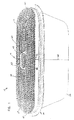
図1を参照して、図1は第1の実施形態の濾過パックあるいは濾過エレメント10を示した外観斜視図である。本図において、望ましくは、濾過エレメント10は、媒体12、ハンドル手段14およびシール手段16を含んでいる。濾過媒体12は、内部を通過する空気のような流体から微粒子を取り除くように設計される。望ましくは、ハンドル手段14は、 整備点検か交換のために濾過エレメント10の便利な操作と取り扱いを容易にするために構成される。シール手段16は、濾過媒体12とダクトの内壁の間で密閉のためのシールを形成するように設計される。
【0008】
図1において、濾過エレメント10は、直線的な流れを許容するように構成される。この「直線的な流れ」という用語は、入り口の面で入って対向する出口の面を出るまでに、流体の流動の方向が同じ方向を維持して流れることを意味する。例えば、濾過エレメント10は、第1端部20とこれに対向して配置される第2の端部22を規定している。いくつかの構成では、第1の端部は流れの上流側に位置し、第2の端部は下流側に位置するように対応する。他の構成によれば、第1の端部が流れの下流側に、また第2の端部が流れの上流側に位置することもできる。直線的な流れにより、気流が第1の端部20を入り第2の端部22から出るようにして、第1の端部20に向かう気流の方向を第2の端部22から出る気流の方向と同じにすることができる。この直線的な流れを通して、気流の乱れの量を減少させることができる。
【0009】
次に、図2を参照して、図2は、濾過構成の濾過エレメントで使用可能な濾過媒体の一部の概要を示した外観斜視図である。本図において、流路構成が122で示されている。望ましくは、流路構成122は、多数の流路124と面シート132を有する波形のシート123を含んでいる。図2の具体例では、二つの面シート132が用いられ、132A(波形の層123の上に示される)と、132B(波形のシート123の下に示される)とが使用される。通常、媒体構成125の媒体は下部の面シート132Bに固定される波形のシート123を含む。この媒体構成125を巻回状態で使用する場合には、それ自体の周りに通常巻き上げられることで、下部の面シート132Bが波形のシート123の頂点部分を覆うようにする。波形のシートの頂点部分を覆う表面シート132は132Aとして表現されている。以上で、面シートの132Aと132Bとが同じシート132であることが理解されるであろう。
【0010】
この形式の媒体構成125を使用する場合には、望ましくは、流路室124は交替する頂点126と谷部128を形成すると良い。谷部128と頂点126は、流路を上側の列と下側の列に分割する。特に図2に示される構成によれば、上方の流路は下流の端部で閉じた流路室136を形成する一方で、上流側端部部位を閉じた流路を有する流路室134は下方の流路列を形成する。流路室134は第1端部の玉状封止材138で塞がれている。この玉状封止材138は、流路シート130と第2の面シート132Bの間の流路の上流側端部部位を満たすように設けられる。同様に、第2の端部の玉状封止材140が交替する流路136の下流側の端部部位を塞ぐ。いくつかの構成では、第1の端部の玉状封止材138と第2の端部の玉状封止材140の双方とも媒体構成125の一部に沿うようにまっすぐに設けられ、それないように設けられる。また、別の構成では、第1の端部の玉状封止材138は直線的であって、媒体構成125の端部部位からそれないように設けられる一方で、第2の端部の玉状封止材140も直線的であって、媒体構成125の端部部位からそれないように設けられる。
【0011】
媒体構成125の形状として使用されるときに、空気を含む流体は使用中は陰影をつけ矢印144で示されるように流路室136に入る。流路室136は開口した上流端部146を有している。濾過前の流体は、下流側の端部148が第2の端部の玉状封止材140により閉じられているので、流路室136の下流側の端部148を通過しない。したがって、 流体は流路のシート130または面シート132を強制的に通過せざるを得ない。濾過前の流体がシート130または面シート132を通り抜けるとき、 流体は浄化または濾過される。浄化された流体は陰影をつけていない矢印150で示されている。続いて、流体は 流路室134(上流の端部151が閉じた)を通り抜けて、流路構成122の開口した下流側の端部を抜ける。図示の構成で、濾過前の流体は流路を流路シート130と、上側の面シート132Aと、下側の面シート132Bを通過して、流路室134の中に流れ込むことができる。
【0012】
典型的には、媒体構成125が準備され、巻かれてロール状の濾過媒体を形成する。このタイプの媒体が使用のために選択される場合には、媒体構成125は、端部の玉状封止材138により下方の面シート132B(図2に示されるように、上方の面シート132Aがない状態で)固定される波形のシート123を含む。これらのタイプの構成125は、一方端の先頭縁部と反対側の後端縁部を含み、この先頭縁部を後端縁部の間に延設される上部の縁部と下部の縁部を有する。この「先頭縁部」で意味することは、初めに縁部が方向転換されるか巻かれて、芯を形成するか芯に隣接して巻かれることを言う。また「後端部」は、巻かれた後にロール状に巻かれた構成の外部の縁部となる。
【0013】
以上の先頭縁部と後端部は、シートを巻き上げて媒体構成125を完成する前に波形のシート123と下部の面シート132Bの間で密封されるべきである。これには、多くの方法が可能であるが、例えば先頭縁部のシールは以下の通りに形成される。(a) 波形のシート123と下部の面シート132Aは頂点126の最も高いポイント(または, 頂点)で頂点126を形成する流路124に沿って、上部の縁部から下部の縁部(または下部の縁部から上部の縁部)を広げる線または経路に沿って切られるかまたは切り分けられる。(b) そして、 シーラントは下部の面シート132Bと波形のシート123の間において、カットの線か経路に沿って塗布される。これの先頭縁部におけるシール形成と似た方法で後端部のシールを形成することができる。多くの異なったタイプのシーラントはこれらのシールを形成するのに使用されるが、 1つの使用可能な材料として米国ミネソタ州、セント・ポールのH.B.Fullerから名称HL0842として提供される非発泡のシーラントが挙げられる。
【0014】
この媒体構成125を使用するとき、 濾過媒体を巻き上げるように構成することで図1に図示される濾過エレメント10にすることは設計者に望まれる場合がある。媒体を巻き付けるコイル状にするか、またはロール状に構成するためにはさまざまな方法がある。例えば、媒体構成125は中心の芯30の周りに巻きつけられるか、巻きつけのために他の部材を使用しても良い。
【0015】
濾過エレメント10を構成する際に、 通常は、図2に示された濾過媒体122のように一方の面のみに面した濾過媒体は、中心の芯30(図1に示す)の周りで巻き上げられる状態が螺旋状に設けられる。他の実施例では、芯30は円形または長手方向に短い矩形、四角形他の部材として設けられる。この濾過エレメント10を製造するときに、濾過媒体122は芯30にしっかりと固定されることで、芯30と濾過媒体の最初の巻きつけ部分の間において気流の漏れがないように取り付けられる。
【0016】
好ましい構成では、芯30は濾過エレメント10の第1の端部20と第2の端部22の間で軸方向に延設する長さを有すると良い。以下において詳細に述べるように、芯30はその端部においてハンドル手段14と協働するために上記の第1の端部20から突出するかその上に気流の流れに沿う軸線方向に延設される部位を形成している。
【0017】
濾過エレメント10のように巻かれた構造を有した濾過構成を使用するときに、設計者は濾過エレメント10の外側の周辺が濾過エレメント10から解かれるのを防ぐために適所で閉じるか、または係止することを確実にしなければならない。これを達成するためにはさまざまな方法がある。いくつかの適用例においては、外側の周辺は周辺層で包装される。この周辺層は一方の面の上に接着剤を塗布したプラスチックなどの非多孔性の粘着材料がある。このタイプの周辺層が利用されることで、濾過構成10が解かれるのが防がれ流体が濾過構成10の外の周辺を通り抜けるのを防ぐようにして、濾過構成10を直線的に流れるように維持できる。
【0018】
また、いくつかの応用例では、濾過エレメント10はロール状構造でありながらその外部において濾過構成125の後端部を線160(図1)に沿って接着剤かシーラントで固定する場合がある。例えば、 熱溶融状態の玉状封止材を線160に沿って塗布しても良い。
【0019】
再度、図1を参照して、図示のように濾過エレメント10の横断面形状は非円形である。濾過エレメントの横断面の形は設置される空間の幾何学上から円形が可能であるが、非円形の横断面図を有した方が時々便利となる。この非円形の横断面形状によれば、 比較的多量の濾過媒体をわずかな体積中に収容できる。いくつかの好まれた構造では、濾過エレメント10の横断面の構成は長円(楕円ではない)がよい。図1で示される特定の具体化において、 濾過エレメント10の断面が競馬場の走行路形に形成される。この競馬場の走行路形とは濾過エレメント10は半円の端部40と反対の半円の端部42を規定し、これらの半円の端部40と端部42が1組のまっすぐな区分44、46で接合されることを意味する。
【0020】
また、好まれた構造では、濾過エレメント10は濾過エレメント10に固定されるハンドル手段14を含む。このハンドル手段14は人間の手の一部によって適用される握り力を収容するために組み立てられ取り付けられる。これは濾過エレメント10の整備点検または交換時における便利な操作を可能にする。
【0021】
好まれたハンドル手段14は濾過エレメント10に固定されており、ハンドル手段14に適用される引き力が濾過エレメント10の引き力として伝わるように構成される。ほとんどの好まれるハンドル手段14は、芯30に固定される。このために、媒体12の一部は障害とならず、またハンドル手段の接続部分を設ける必要がなくなる。
【0022】
さまざまな方法で芯30にハンドル手段14を固定することができる。例えば、ハンドル手段14は接着されるか、ねじなどの機械的な締結手段で取付けられるか、または繋ぎ縄で接続される。さらに、ハンドル手段14は蝶番または他の機構を介して芯30に取り付けられた回動自在の棒体でも良い。
【0023】
依然として図1を参照して、特定の具体例におけるハンドル手段14は芯30と一体形成される。さらに、図1の好ましい具体例では、 ハンドル手段16は芯30とともに一体成型される。この一体成型は製造上で好都合であり、かつ簡単な組立が可能となる。
【0024】
望ましくは、ハンドル手段14は芯30により規定され、芯30を通り抜ける開口部50を含む。好まれた構成手段では, 開口部50は芯30に入り込む一つ以上の開口部を含む。図1では開口部50が一つである場合が示されており、延設されたスロット58を有している。好ましくはスロット58は使用者の手の一部である平均の人間の手の3乃至4本の指またを収容する大きさに設定される。ユーザは次に、指をスロット58に挿入し、ハンドル手段14の一部を把持して濾過エレメント10を操作する。
【0025】
図5を参照して以下に述べる。ある具体例では、ハンドル手段14は一つ以上の開口部または多数または多重の開口部70を備える。図5の具体例では3つ未満の開口部72、74、76が設けられている。他の具体例では、2つの開口部または4つの開口部でも良い。各開口部72、74、76は円形である。望ましくは、それぞれの開口部72、74、76の直径は、手袋によって保護される人間の指を収容することができる大きさに設定される。
【0026】
次に、図3を参照して以下に述べる。図3において、シール手段16が正面図で示されている。シール手段16は濾過エレメント10の外側の周辺に固定されるシール部材またはガスケット90を通常含む。いくつかの具体例において、シール部材90は円形の横断面形状のシール部材を含むことができる。図3で示される具体例では、シール部材90はL字形の横断面図を規定している。特に、バンド92は、濾過エレメント10を取り囲み濾過エレメント10の側壁に対して実質的に平行な表面を含むように設けられる。突出したフランジ94の広がりかバンド92から形成される。ダクトに挿入されると、フランジ94によりリップシールまたは挿入軸方向のシールを作成するのを助けるためにバンド92側に向かって通常偏向するように傾けられる。
【0027】
図4はシール部材90の代替の具体例の図である。図4では、バンド96は突出したフランジ98の下方に設けられる。この具体例では, 濾過エレメント10がダクトに装填されるときに、フランジ98がバンド96から離れるように傾くように変形して、濾過エレメント10の第1の端部20に指向するように偏向される。
【0028】
濾過エレメント10の追加の図面は米国特許出願番号 29/101、304の「ハンドルを有する濾過エレメント」に表現されている。
【0029】
B.図6の構成
図6を参照して以下に述べる。図6は、濾過エレメント10が使用可能なシステム100であり、店舗用の真空装置や他の同様のエアクリーナーなどの装置104を含む。この装置104は、真空状態を引き起こすファンと、ファンを駆動するモータ106を具備する。シール部材90が濾過エレメント10とダクト110の間でシール112を形成して、 濾過エレメント10をダクト110に装填できるように構成されている。典型的なシステムに関する1つの例が米国特許出願番号09/251、022の名称「エアフィルタ構成と方法」において記述されているので盛り込んだ。
【0030】
稼働中に微粒子を含んだ空気などの流体が矢印114で示される方法に装置104内に引き込まれる。次に、流体は濾過エレメント10を通過して微粒子の浄化が行われる。浄化された空気または流体は次に装置104から矢印116方向に排気される。いくつかのシステムでは、入って来る流体114から如何なる大きい汚染物質であっても完全に取り除くために濾過エレメント10の上流にふるいまたは網目の任意のプレ濾過118を設けると良い。
【0031】
使用の一区切りの使用後に、濾過エレメント10は点検する必要がある。この濾過エレメント10が詰まる状態になり、システム100に高い制限を加える状態となったときに、濾過エレメント10は交換される。この交換作業は、装置104の内部に近づくことによって行うことができる。このとき、ハンドル手段14がユーザの手で把持される。例えば、ユーザの指は芯30により定義される開口部50に入り込む。そして、ユーザは濾過エレメント10への引き力として伝達されるハンドル14に対して引き力を加える。濾過エレメント10を引くときに、シール112はダクト110と濾過エレメント10の間で壊れる状態となる。そして, 濾過エレメント10は装置104から取り除かれる。濾過エレメント10は掃除するか取り替えることができる。濾過エレメント10を処分して新しい状態となるように取り替えることができ2番目の濾過はエレメントが装填できる。濾過エレメント10を掃除するときには、上流の端部の流路が下向きになるようにして行う。ユーザは、これらの流路の中に集まった汚染物質、ほこりまたは残骸を落とすために下流側の端部を軽くたたくかもしれない。シール112を壊してダクト110から濾過エレメント10を取り除くために要する引く力は、低いことから手で十分にできる。その引く力は50ポンド以下の30ポンドで良く、15ポンドでも可能である。
【0032】
そして、 濾過エレメント10を装置104に再度装填するときには、ハンドル手段14を把持して、濾過エレメント10をダクト110に挿入することによって行うことができる。このときシール112がダクト110と濾過エレメント10の間で形成されるまで、濾過エレメント10を奥に挿入する。ユーザは次にハンドル手段14から手を放し装置104のアクセスポートを閉じることで操作を完了する。
【0033】
C.使用材料例
以下のセクションは上記の構成手段で使用可能な材料例について述べるが、これ以外の材料も使用可能である。
【0034】
濾過媒体12は以下の特性のセルロース媒体である。
【0035】
およそ52ポンド/3000平方フィート(84.7g/平方m)の基礎の重さ、およそ厚さ0.010インチ(0.25mm)、およそ22フィート/分(6.7m/分)のフレイザー(frazier)透過率、およそ62ミクロンのサイズの開口寸法、8.5ボンド/インチ(3.9g/インチ)の張力、ウエットオフマシーンの炸裂強度がおよそ23psi(59kPa)である。セルロース媒体は微細な繊維である、例えば5ミクロンあるいはそれ未満のサイズ(直径)を持っている繊維が使用され、いくつかの例ではサブミクロンの繊維を利用することができる。例えば、このようないくつかのアプローチが米国特許番号5、432、892の第32欄、第48−50行目に記載されている。より詳しくは米国特許番号3、878、014号、3、676、242号、3、841、953号、3、849、241号に記載されている。別の代替手段は企業秘密の下で名称ウルトラ・ウエブ(商標)でありドナルドソンカンパニーによって練習された従来の媒体の上に置かれるすばらしい重合の繊維ウエブ包括する。濾過エレメントの構成とハンドルの操作に関して微細な繊維がどのように作られていてどんな特定の方法を適用するのに使用されるのかは関係ない。結果としての媒体構成は以下の特性を得るために十分に微細な繊維が適用される。平均99.5%の初期効率はSAEのSAE J726Cに従ってテストされ90%の個々のテストなしで平均される。そして SAE J726Cに従ったテストで99.98%の平均の総合的な効率を得る。
【0036】
芯30は構造的な保全を提供するために、クリープ現象が発生しない材料から構成される。好まれた構成によれば芯30は容易に再生利用可能な非金属の材料であり、環境面で好意的な容易に焼却できる材料から構成、組み立てられる。例えばほとんどのプラスチック、ポリプロピレン、ABSまたはナイロンからハンドル手段14を含む芯30を組み立てることができる。 さらに芯30は固い紙の板から組み立てられる。
【0037】
シール材90は柔らかい圧縮性の素材から組み立てられる。例えば、密度約2−10ポンド/立方フィートのポリウレタンからシール90を組み立てることができる。
【0038】
D.構造例の寸法
以下に濾過構成の寸法について述べるが、これに限定されず異なる応用において、他の寸法が使用可能である。
【0039】
濾過エレメント10は、断面形状が競馬場の走行路に近似している。対向するまっすぐな区分44、46の間の幅寸法は2−10インチであり、好ましくは5インチである。対向する半円の端部40、42の間の長さは例えば5−30インチ、15−25インチであり、好ましくは18インチである。第1の端部20と第2の端部22の間の高さは例えば2−30インチ、5−15インチであり、好ましくは8−12インチである。濾過エレメントは媒体表面積の少なくとも30平方フィートあり、通常は50−150平方フィート、70−100平方フィートである。
【0040】
ハンドル手段14は第1の端部から0.5−5インチの間で突出形成されており、例えば0.75-2インチ、好ましくは1インチ突出する。
【0041】
スロット58は例えば2−20平方インチ、3−8平方インチ、または4平方インチの開口面積を有する。
【0042】
それぞれの開口部74,76、78は0.75-3インチの直径であり、好ましくは1インチが良い。
【0043】
尚、本発明は特許請求の範囲に規定される種々の構成が可能であり、上記の実施例に限定されないことは言うまでもない。
【図面の簡単な説明】
【図1】 図1は、本開示の原理に従った濾過エレメントの第1の実施形態を示した外観斜視図である。
【図2】 図2は、図1で示された濾過エレメントで使用可能な濾過媒体の一部の概要を示した外観斜視図である。
【図3】 図3は、図1に図示の濾過エレメントの正面図である。
【図4】 図4は、図1の濾過原理に従って取り付けられたシール部材の一部を示した拡大図である。
【図5】 図5は、本開示の原理に従った濾過エレメントの第2の実施形態を示した外観斜視図である。
【図6】 図6は、濾過原理を使用したシステムの模式図である。[0001]
(Field of Invention)
This disclosure relates to a filtration structure for filtering a fluid such as a gas or a liquid, and more particularly to a filtration element having a handle.
[0002]
(Background of the Invention)
Filtration elements are used in systems that purify fluid that passes in a linear flow. In order to pass a straight flow, the filter element usually has an exit side surface arranged opposite the entrance side surface. In this way, the fluid flows in one direction as it enters the filtration element from the inlet side surface and has the same direction of flow as it exits the outlet side surface. Usually, a filtering element having a linear flow is loaded into some type of duct or housing. In use, the filter element must be serviced after a break to clean or completely replace. If the work to service the filter element is difficult or inconvenient to replace, the user will delay proper maintenance, and thus delaying maintenance will cause damage in any system that requires filtration. become. For this reason, it is desirable to improve the linear flow filtration element.
[0003]
(Summary of disclosure)
One configuration of the filtration configuration is disclosed. In one form, the filtration configuration includes a filtration element and a handle member secured to the filtration element. The filter element is constructed through a linear flow. For example, a filtration element is usually provided with a first end, an opposing second end, and many flow paths. Each flow path has a first end portion adjacent to the first end of the filtration element and a second end portion adjacent to the second end of the filtration element. These first and second end portions are alternately closed so as to close the flow path. The handle member is usually assembled and secured to convey the grip force applied by a part of the human hand.
[0004]
Desirably, the flow path of the filtration element includes a coil portion that is wound around the main core member.
[0005]
In another preferred embodiment, the handle member is fixed to the central core member.
In yet another configuration, a system for loading a duct with a filtration element in a filtration system is described. A method for servicing a filtration system in which a filtration element is configured through a linear flow includes a configuration that grips a handle secured to the filtration element and pulls the handle to remove the filtration element from the duct.
[0006]
DESCRIPTION OF THE PREFERRED EMBODIMENT
A. See FIGS. 1-5.
[0007]
Referring to FIG. 1, FIG. 1 is an external perspective view showing a filter pack or
[0008]
In FIG. 1, the
[0009]
Next, referring to FIG. 2, FIG. 2 is an external perspective view showing an outline of a part of a filtration medium that can be used in a filtration element having a filtration configuration. In this figure, the flow path configuration is indicated by 122. Desirably, the
[0010]
When this type of
[0011]
When used as the shape of the
[0012]
Typically, a
[0013]
These leading and trailing edges should be sealed between the
[0014]
When using this
[0015]
In constructing the
[0016]
In a preferred configuration, the
[0017]
When using a filtration configuration having a wound configuration, such as
[0018]
Also, in some applications, the
[0019]
Referring again to FIG. 1, the cross-sectional shape of the
[0020]
Also in the preferred construction, the
[0021]
The preferred handle means 14 is fixed to the
[0022]
The handle means 14 can be secured to the core 30 in a variety of ways. For example, the handle means 14 can be glued, attached with mechanical fastening means such as screws, or connected with a tether. Further, the handle means 14 may be a pivotable rod attached to the
[0023]
Still referring to FIG. 1, the handle means 14 in a particular embodiment is integrally formed with the
[0024]
Desirably, the handle means 14 is defined by a
[0025]
This will be described below with reference to FIG. In certain embodiments, the handle means 14 comprises one or more openings or multiple or multiple openings 70. In the specific example of FIG. 5, less than three
[0026]
Next, it will be described below with reference to FIG. In FIG. 3, the sealing means 16 is shown in a front view. The sealing means 16 typically includes a sealing member or
[0027]
FIG. 4 is a diagram of an alternative embodiment of the
[0028]
Additional drawings of the
[0029]
B. The configuration will be described below with reference to FIG. FIG. 6 is a
[0030]
During operation, a fluid such as air containing particulates is drawn into the device 104 in the manner indicated by arrow 114. Next, the fluid passes through the
[0031]
After a single use, the
[0032]
Then, when the
[0033]
C. Examples of materials used The following sections describe examples of materials that can be used with the above construction means, but other materials may be used.
[0034]
The filtration medium 12 is a cellulose medium having the following characteristics.
[0035]
Approximately 52 pounds / 3000 square feet (84.7 g / square meter) basis weight, approximately 0.010 inches (0.25 mm) thick, approximately 22 feet / minute (6.7 m / minute) frazier ) Transmittance, aperture size approximately 62 microns in size, 8.5 bond / inch (3.9 g / inch) tension, wet-off machine burst strength approximately 23 psi (59 kPa). Cellulose media are fine fibers, for example, fibers having a size (diameter) of 5 microns or less , and in some cases submicron fibers can be utilized. For example, several such approaches are described in US Pat. No. 5,432,892, column 32, lines 48-50. More details are described in US Pat. Nos. 3,878,014, 3,676,242, 3,841,953, 3,849,241. Another alternative involves the superbly polymerized fiber web, which is placed under the trade name, Ultra Web ™, on conventional media practiced by the Donaldson Company. It does not matter how the fine fibers are made and what specific method is used to apply with regard to the construction of the filter element and the handling of the handle. The resulting media configuration is applied with sufficiently fine fibers to obtain the following characteristics. An average efficiency of 99.5% is tested according to SAE SAE J726C and averaged without 90% individual tests. And testing according to SAE J726C gives an average overall efficiency of 99.98%.
[0036]
The
[0037]
The sealing
[0038]
D. Dimensions of structural examples The dimensions of the filtration configuration are described below, but are not so limited and other dimensions can be used in different applications.
[0039]
The
[0040]
The handle means 14 is projected between 0.5-5 inches from the first end, for example 0.75-2 inches, preferably 1 inch.
[0041]
The
[0042]
Each
[0043]
In addition, it cannot be overemphasized that the various structures prescribed | regulated by a claim are possible for this invention, and it is not limited to said Example.
[Brief description of the drawings]
FIG. 1 is an external perspective view showing a first embodiment of a filtration element according to the principles of the present disclosure.
FIG. 2 is an external perspective view showing an outline of a part of a filtration medium that can be used in the filtration element shown in FIG. 1;
FIG. 3 is a front view of the filter element shown in FIG. 1;
FIG. 4 is an enlarged view showing a part of a seal member attached according to the filtration principle of FIG. 1;
FIG. 5 is an external perspective view showing a second embodiment of a filtration element according to the principles of the present disclosure.
FIG. 6 is a schematic diagram of a system using the filtration principle.
Claims (13)
(a)前記濾過装置は、互いに対向する第1及び第2の端部(20、22)を有する濾過エレメント(10)を備え、前記濾過エレメントは、少なくとも1枚の波形の濾過媒体(123)と、前記少なくとも1枚の波形の濾過媒体の近傍に配置される少なくとも1枚の非波形の濾過媒体(132)とを具備する片面の濾過媒体(122)を含み、 (A) The filtration device comprises a filtration element (10) having first and second ends (20, 22) facing each other, the filtration element comprising at least one corrugated filtration medium (123). And at least one non-corrugated filter medium (132) disposed in the vicinity of the at least one corrugated filter medium,
(i)前記少なくとも1枚の波形の濾過媒体と前記少なくとも1枚の非波形の濾過媒体とは互いに固定され、 (I) the at least one corrugated filtration medium and the at least one non-corrugated filtration medium are fixed to each other;
(ii)前記少なくとも1枚の波形の濾過媒体は、複数の流路(124)を形成する、交互に出現する頂点(126)と谷部(128)とを備え、 (Ii) the at least one corrugated filtration medium comprises alternating vertices (126) and troughs (128) forming a plurality of channels (124);
(A)前記流路のそれぞれは、前記濾過エレメントの第1の端部の近傍の第1の端部部位と、前記濾過エレメントの第2の端部の近傍の第2の端部部位とを有し、 (A) Each of the flow paths includes a first end portion in the vicinity of the first end portion of the filtration element and a second end portion in the vicinity of the second end portion of the filtration element. Have
(B)前記流路の一部は、前記第1の端部部位で開口し、前記第2の端部部位において閉じており、 (B) a portion of the flow path is open at the first end portion and closed at the second end portion;
(C)前記流路の他の一部は、前記第1の端部部位で閉じ、前記第2の端部部位において開口しており、 (C) The other part of the flow path is closed at the first end portion and opened at the second end portion,
(b)前記濾過エレメントは、中央芯部材(30)を含み、 (B) the filtration element includes a central core member (30);
(i)前記中央芯部材は、細長い非円形構造を備え、 (I) the central core member has an elongated non-circular structure;
(ii)前記片面の濾過媒体は、前記片面の濾過媒体と前記中央芯部材との間のガスの流れを防止するように、前記中央芯部材にしっかりと取り付けられ、 (Ii) the one-side filtration medium is firmly attached to the central core member so as to prevent a gas flow between the one-side filtration medium and the central core member;
(c)前記濾過エレメントの操作を可能にするために、ハンドル部材(14)が前記濾過エレメント(10)の前記第1の端部(20)から軸線方向に突出し、 (C) a handle member (14) projects axially from the first end (20) of the filter element (10) to allow operation of the filter element;
(i)前記ハンドル部材は、前記中央芯部材と一体成型されており、 (I) The handle member is integrally molded with the central core member,
(d)前記濾過エレメント(10)は、非円形の断面形状を有する、 (D) the filtration element (10) has a non-circular cross-sectional shape;
ことを特徴とする濾過装置。A filtering device characterized by that.
(a)前記方法は、ダクト(110)に装填される濾過エレメント(10)を有するシステム(100)を提供する工程を含み、前記濾過エレメントは、互いに対向する上流側及び下流側の端部を含み、前記濾過エレメントは、複数の流路を有し、前記流路のそれぞれは、前記濾過エレメントの上流側の端部の近傍の第1の端部部位と前記濾過エレメントの下流側の端部の近傍の第2の端部部位とを有し、前記流路の一部は、前記第1の端部部位で開口し、前記第2の端部部位において閉じており、前記流路の他の一部は、前記第1の端部部位で閉じ、前記第2の端部部位において開口しており、 (A) the method includes providing a system (100) having a filter element (10) loaded into a duct (110), the filter element having upstream and downstream ends opposite to each other; The filtration element has a plurality of flow paths, and each of the flow paths has a first end portion in the vicinity of an upstream end portion of the filtration element and a downstream end portion of the filtration element. A part of the flow path that is open at the first end part and closed at the second end part. Is closed at the first end portion and opened at the second end portion,
(b)前記方法は、前記濾過エレメントに固定されたハンドル(14)を握る工程を含み、 (B) the method includes the step of grasping a handle (14) secured to the filtration element;
(c)前記方法は、前記システムの前記ダクトから前記濾過エレメントを取り除くために前記ハンドルを引く工程を含む、 (C) the method includes pulling the handle to remove the filtration element from the duct of the system;
ことを特徴とする方法。A method characterized by that.
(a)前記方法は、システム(100)にダクト(110)を提供する工程を含み、 (A) the method includes providing a duct (110) to the system (100);
(b)前記方法は、互いに対向する上流側及び下流側の端部と複数の流路とを含む濾過エレメントを提供する工程を含み、前記流路のそれぞれは、前記濾過エレメントの上流側の端部の近傍の第1の端部部位と前記濾過エレメントの下流側の端部の近傍の第2の端部部位とを有し、前記流路の一部は、前記第1の端部部位で開口し、前記第2の端部部位において閉じており、前記流路の他の一部は、前記第1の端部部位で閉じ、前記第2の端部部位において開口しており、 (B) the method includes providing a filtration element including upstream and downstream ends facing each other and a plurality of flow paths, each of the flow paths being an upstream end of the filtration element; A first end portion in the vicinity of the portion and a second end portion in the vicinity of the downstream end portion of the filtration element, and a part of the flow path is at the first end portion. Open and closed at the second end portion, the other part of the flow path is closed at the first end portion and opened at the second end portion,
(c)前記方法は、前記濾過エレメントに固定されたハンドル(14)を握る工程を含み、 (C) the method includes the step of grasping a handle (14) secured to the filtration element;
(d)前記方法は、前記ハンドルを用いて前記濾過エレメントを前記システムの前記ダクト内に配置する工程を含む、 (D) the method includes using the handle to place the filter element in the duct of the system;
ことを特徴とする方法。A method characterized by that.
Applications Claiming Priority (3)
| Application Number | Priority Date | Filing Date | Title |
|---|---|---|---|
| US09/259,489 | 1999-02-26 | ||
| US09/259,489 US6235195B1 (en) | 1999-02-26 | 1999-02-26 | Filter element incorporating a handle member |
| PCT/US2000/004575 WO2000050153A1 (en) | 1999-02-26 | 2000-02-23 | Filter element having a handle |
Publications (3)
| Publication Number | Publication Date |
|---|---|
| JP2002537103A JP2002537103A (en) | 2002-11-05 |
| JP2002537103A5 JP2002537103A5 (en) | 2011-07-14 |
| JP4860042B2 true JP4860042B2 (en) | 2012-01-25 |
Family
ID=22985171
Family Applications (1)
| Application Number | Title | Priority Date | Filing Date |
|---|---|---|---|
| JP2000600758A Expired - Fee Related JP4860042B2 (en) | 1999-02-26 | 2000-02-23 | Filtration element with handle |
Country Status (15)
| Country | Link |
|---|---|
| US (1) | US6235195B1 (en) |
| EP (4) | EP2269708A1 (en) |
| JP (1) | JP4860042B2 (en) |
| KR (1) | KR100630425B1 (en) |
| CN (2) | CN101347696B (en) |
| AT (2) | ATE263612T1 (en) |
| AU (1) | AU776588B2 (en) |
| BR (1) | BR0008460B1 (en) |
| CA (1) | CA2362189A1 (en) |
| DE (2) | DE60045747D1 (en) |
| ES (1) | ES2221839T3 (en) |
| ID (1) | ID30473A (en) |
| RU (1) | RU2001124860A (en) |
| WO (1) | WO2000050153A1 (en) |
| ZA (1) | ZA200106729B (en) |
Families Citing this family (161)
| Publication number | Priority date | Publication date | Assignee | Title |
|---|---|---|---|---|
| EP0904143B1 (en) | 1996-04-26 | 2003-06-18 | Donaldson Company, Inc. | Fluted filter media |
| US6190432B1 (en) | 1999-02-26 | 2001-02-20 | Donaldson Company, Inc. | Filter arrangement; sealing system; and methods |
| CN1201845C (en) * | 1999-02-26 | 2005-05-18 | 唐纳森公司 | Sealing system for filter |
| US6676721B1 (en) * | 2000-06-02 | 2004-01-13 | Donaldson Company, Inc. | Multistage air cleaner including pulse cleaning system |
| US6348084B1 (en) | 1999-11-05 | 2002-02-19 | Donaldson Company, Inc. | Filter element, air cleaner, and methods |
| US8449638B2 (en) | 1999-11-05 | 2013-05-28 | Donaldson Company, Inc. | Filter element, air cleaner, and methods |
| US6673136B2 (en) * | 2000-09-05 | 2004-01-06 | Donaldson Company, Inc. | Air filtration arrangements having fluted media constructions and methods |
| US6743317B2 (en) | 2000-12-19 | 2004-06-01 | Robert M. Wydeven | Method of sealing, housing and constructing honeycomb filters |
| US6517598B2 (en) | 2001-06-06 | 2003-02-11 | Donaldson Company, Inc. | Filter element having flange and methods |
| US6610126B2 (en) | 2001-06-06 | 2003-08-26 | Donaldson Company, Inc. | Filter element having sealing members and methods |
| US6852141B2 (en) * | 2001-06-06 | 2005-02-08 | Donaldson Company, Inc. | Filter element having center piece and methods |
| CN1319624C (en) * | 2001-12-03 | 2007-06-06 | 唐纳森公司 | Media, filter element using corrugated media sheet, corrugated sheet, and methods |
| US6966940B2 (en) * | 2002-04-04 | 2005-11-22 | Donaldson Company, Inc. | Air filter cartridge |
| WO2003095068A1 (en) | 2002-05-09 | 2003-11-20 | Donaldson Company, Inc. | Air filter having fluted filter media |
| MXPA05000459A (en) | 2002-07-10 | 2005-03-23 | Donaldson Co Inc | Fluted filter medium and process for its manufacture. |
| EP1556156B1 (en) * | 2002-08-08 | 2008-10-08 | Mann+Hummel Gmbh | Filter system |
| DE60327890D1 (en) | 2002-12-11 | 2009-07-16 | Donaldson Co Inc | Z-FILTER MEDIA WITH AGGREGATE CLEANING SYSTEMS AND METHOD |
| KR20050098922A (en) | 2003-02-11 | 2005-10-12 | 도널드선 컴파니 인코포레이티드 | Air cleaner arrangements; serviceable filter elements;and,method |
| ATE469692T1 (en) | 2003-03-18 | 2010-06-15 | Donaldson Co Inc | IMPROVED METHOD FOR WINDING Z-FILTER MEDIA |
| US6955696B1 (en) * | 2003-07-31 | 2005-10-18 | Filtration Group, Inc. | Filter frame and assembly |
| ATE503551T1 (en) * | 2003-11-12 | 2011-04-15 | Donaldson Co Inc | AIR FILTER WITH A SLIDING BRACKET FOR FILTRATION ELEMENT |
| US20090266041A1 (en) * | 2003-12-22 | 2009-10-29 | Donaldson Company, Inc. | Seal arrangement for filter element; Filter element assembly; and, methods |
| AU2004308945B2 (en) | 2003-12-22 | 2011-03-10 | Donaldson Company, Inc. | Filter element comprising a seal arrangement and method for making the same |
| US7235121B2 (en) * | 2003-12-26 | 2007-06-26 | West Timothy J | Externally removable vacuum cleaner filter apparatus |
| US20050178719A1 (en) * | 2004-02-12 | 2005-08-18 | Pank Thomas E. | Filter in the form of a roll and the method of making the same |
| ATE477041T1 (en) * | 2004-02-17 | 2010-08-15 | Donaldson Co Inc | AIR PURIFIER ASSEMBLY, SERVICEABLE FILTER ELEMENTS AND METHODS |
| CN101816872B (en) | 2004-03-24 | 2013-12-11 | 唐纳森公司 | Filter elements, air cleaner, assembly, and methods |
| GB0409548D0 (en) * | 2004-04-29 | 2004-06-02 | King S College London | Robotic hand |
| US7905936B2 (en) | 2004-04-30 | 2011-03-15 | Donaldson Company, Inc. | Filter arrangements; housing; assemblies; and, methods |
| EP1748831B1 (en) * | 2004-04-30 | 2012-06-13 | Donaldson Company, Inc. | Filter assemblies and method |
| MXPA06014395A (en) | 2004-06-08 | 2007-02-19 | Donaldson Co Inc | Z-filter media pack arrangements; and, methods. |
| EP2243536B1 (en) | 2004-06-14 | 2013-11-20 | Donaldson Company, Inc. | Air filter arrangement and cartridge |
| US20050276862A1 (en) * | 2004-06-15 | 2005-12-15 | Bringley Joseph F | Iron sequestering antimicrobial composition |
| US8048188B2 (en) | 2004-06-18 | 2011-11-01 | Donaldson Company, Inc. | Air cleaner arrangements; serviceable filter cartridge; and, methods |
| US8016903B2 (en) * | 2004-07-20 | 2011-09-13 | Donaldson Company, Inc. | Z-filter media pack arrangement; filter cartridge; air cleaner arrangement; and, methods |
| EP3135363B1 (en) | 2004-08-06 | 2021-06-30 | Donaldson Company, Inc. | Air filter arrangement; assembly; and, methods |
| DE102004050018A1 (en) * | 2004-10-13 | 2006-04-27 | Mann + Hummel Gmbh | air filter |
| US7318851B2 (en) | 2004-11-02 | 2008-01-15 | Baldwin Filters, Inc. | Filter element |
| US20060090431A1 (en) * | 2004-11-02 | 2006-05-04 | Baldwin Filters, Inc. | Filter assembly with combination filter element |
| US8042694B2 (en) * | 2004-11-02 | 2011-10-25 | Baldwin Filters, Inc. | Gathered filter media for an air filter and method of making same |
| US20110197556A1 (en) | 2004-11-02 | 2011-08-18 | Baldwin Filters, Inc. | Filter element |
| US20060091064A1 (en) * | 2004-11-02 | 2006-05-04 | Baldwin Filters, Inc. | Filter apparatus with separable seal support frame |
| US7931725B2 (en) | 2004-11-02 | 2011-04-26 | Baldwin Filters, Inc. | Fluted filter apparatus |
| US20060091061A1 (en) * | 2004-11-02 | 2006-05-04 | Baldwin Filters, Inc. | Filter assembly with sealing system |
| US20060091084A1 (en) * | 2004-11-02 | 2006-05-04 | Baldwin Filters, Inc. | Fluted filter media with intermediate flow restriction and method of making same |
| US20070186528A1 (en) * | 2006-02-15 | 2007-08-16 | Baldwin Filters, Inc. | Fluted filter apparatus |
| US7255300B2 (en) | 2004-11-03 | 2007-08-14 | Baldwin Filters, Inc. | Method and apparatus for winding a filter media pack |
| US7909954B2 (en) * | 2004-11-03 | 2011-03-22 | Baldwin Filters, Inc. | Method and apparatus for winding a filter media pack |
| DE102004059279B4 (en) | 2004-12-09 | 2018-05-03 | Mann + Hummel Gmbh | air filter |
| US7410518B2 (en) * | 2004-12-29 | 2008-08-12 | 3M Innovative Properties Company | Filter removal devices |
| US20060150589A1 (en) * | 2005-01-10 | 2006-07-13 | Crow Marvin S | Filter removal handle |
| ATE548102T1 (en) | 2005-01-13 | 2012-03-15 | Donaldson Co Inc | AIR FILTER ARRANGEMENT |
| EP1850943B1 (en) | 2005-01-13 | 2013-06-05 | Donaldson Company, Inc. | Air filter cartridge and air cleaner assembly |
| US7520913B2 (en) | 2005-02-04 | 2009-04-21 | Donaldson Company, Inc. | Non-cylindrical filter elements, and methods |
| EP1858619A2 (en) * | 2005-02-28 | 2007-11-28 | Donaldson Company, Inc. | Filter arrangement and methods |
| EP2389994B1 (en) * | 2005-03-31 | 2013-06-12 | Donaldson Company, Inc. | Air cleaner assembly |
| US7828869B1 (en) * | 2005-09-20 | 2010-11-09 | Cummins Filtration Ip, Inc. | Space-effective filter element |
| JP2009511264A (en) | 2005-10-11 | 2009-03-19 | ドナルドソン カンパニー,インコーポレイティド | Air filter components, assemblies and methods |
| EP1965888B1 (en) | 2005-11-09 | 2011-08-03 | Donaldson Company, Inc. | Seal arrangement for filter cartridge |
| WO2007084689A2 (en) * | 2006-01-20 | 2007-07-26 | Donaldson Company, Inc. | Air cleaner configured for receipt of various sized filter cartridges; components thereof; and, methods |
| DE202006001440U1 (en) * | 2006-01-31 | 2007-06-14 | Mann+Hummel Gmbh | Filter element and filter system, in particular for the intake air of an internal combustion engine |
| US7753982B2 (en) * | 2006-02-17 | 2010-07-13 | Baldwin Filters, Inc. | Filter with drained jacket, seal indicator/lock means, and seal baffle |
| US7465332B2 (en) * | 2006-04-21 | 2008-12-16 | Gemchar, Llc | Disposable grease filter for air filtration system and method of manufacturing same |
| US7625419B2 (en) * | 2006-05-10 | 2009-12-01 | Donaldson Company, Inc. | Air filter arrangement; assembly; and, methods |
| EP2043758B1 (en) | 2006-06-22 | 2016-11-30 | Donaldson Company, Inc. | Air cleaner assembly and air filter cartridge |
| US7713321B2 (en) * | 2006-06-22 | 2010-05-11 | Donaldson Company, Inc. | Air cleaner arrangements; components thereof; and, methods |
| US8273143B2 (en) | 2006-10-06 | 2012-09-25 | Donaldson Company, Inc. | Air cleaner, replaceable filter cartridges, and methods |
| WO2008064713A1 (en) * | 2006-11-27 | 2008-06-05 | Ateliers Busch Sa | Filter installation device |
| US7588619B2 (en) | 2006-11-28 | 2009-09-15 | Wix Filtration Corp. | Cross-flow filter media and filter assembly |
| US10040020B2 (en) * | 2006-12-06 | 2018-08-07 | Baldwin Filters, Inc. | Fluid filter apparatus having filter media wound about a winding frame |
| US9757676B2 (en) | 2006-12-06 | 2017-09-12 | Baldwin Filters, Inc. | Method and apparatus for winding a filter element |
| EP2514504B1 (en) * | 2007-02-02 | 2018-05-30 | Donaldson Company, Inc. | Air filtration media pack |
| CN101646479B (en) | 2007-02-26 | 2012-10-17 | 唐纳森公司 | Air filter arrangement |
| AU2008268271B8 (en) * | 2007-06-26 | 2014-04-10 | Donaldson Company, Inc. | Filtration media pack, filter elements, and methods |
| US8066791B2 (en) | 2007-07-20 | 2011-11-29 | Donaldson Company, Inc. | Air cleaner arrangements with internal and external support for cartridge; components; and, methods |
| EP2175961B1 (en) | 2007-08-02 | 2016-05-04 | Donaldson Company, Inc. | Crankcase ventilation filter assembly; components; and, methods |
| WO2009033040A1 (en) * | 2007-09-07 | 2009-03-12 | Donaldson Company, Inc. | Air filter assembly; components thereof; and, methods |
| US20090094953A1 (en) * | 2007-10-10 | 2009-04-16 | Mann+Hummel Gmbh | Compact filter element and method for sealing an end thereof |
| US9545593B2 (en) * | 2007-11-01 | 2017-01-17 | Baldwin Filters, Inc. | Winding core pressure relief for fluted filter |
| BRPI0820419B1 (en) | 2007-11-15 | 2021-03-09 | Donaldson Company, Inc | air filter cartridges and air filter assemblies |
| MX2010008530A (en) * | 2008-02-04 | 2010-08-30 | Donaldson Co Inc | Method and apparatus for forming fluted filtration media. |
| US8545585B2 (en) | 2008-02-25 | 2013-10-01 | Donaldson Company, Inc. | Filter element for pulse cleaning and methods |
| US7959703B2 (en) | 2008-06-30 | 2011-06-14 | Baldwin Filters, Inc. | Fluted filter with integrated frame |
| US8048187B2 (en) * | 2008-06-30 | 2011-11-01 | Baldwin Filters, Inc. | Filter frame attachment and fluted filter having same |
| US8741017B2 (en) | 2008-07-22 | 2014-06-03 | Donaldson Company, Inc. | Air cleaner assembly; components therefor; and, methods |
| USD646369S1 (en) | 2008-07-22 | 2011-10-04 | Donaldson Company, Inc. | Filter cartridge |
| CA2731554A1 (en) | 2008-07-25 | 2010-01-28 | Donaldson Company, Inc. | Pleated filtration media, media packs, filter elements, and methods for filtering fluids |
| US8281575B2 (en) * | 2008-07-31 | 2012-10-09 | Caterpillar Inc. | Emissions control filter assembly and system |
| US20100032365A1 (en) * | 2008-08-06 | 2010-02-11 | Ted Anthony Moe | Z-media having flute closures, methods and apparatus |
| US8197687B2 (en) * | 2008-08-19 | 2012-06-12 | Perry Equipment Corporation | Contaminant adsorbent fluted filter element |
| US8317890B2 (en) * | 2008-08-29 | 2012-11-27 | Donaldson Company, Inc. | Filter assembly; components therefor; and, methods |
| WO2010083194A2 (en) | 2009-01-14 | 2010-07-22 | Donaldson Company, Inc. | Filter element; components thereof; and methods |
| WO2010099317A2 (en) | 2009-02-27 | 2010-09-02 | Donaldson Company, Inc. | Filter cartridge; components thereof; and methods |
| US20100243554A1 (en) * | 2009-03-25 | 2010-09-30 | Nathan Herrin | Fluid Filter Assembly |
| US8506668B2 (en) * | 2009-03-30 | 2013-08-13 | Baldwin Filters, Inc. | Fluted filter with axial seal |
| BRPI1014857B1 (en) | 2009-03-31 | 2020-09-15 | Donaldson Company, Inc | AIR FILTER CARTRIDGE, AIR CLEANER AND MAINTENANCE METHOD |
| US8192623B2 (en) | 2009-04-01 | 2012-06-05 | Wix Filtration Corp Llc | Filter structure |
| US8061530B2 (en) | 2009-04-09 | 2011-11-22 | Cummins Filtration Ip, Inc. | Filtration sealing system |
| US8192533B2 (en) * | 2009-06-16 | 2012-06-05 | G.T.E. Industries, Inc. | Support system for exhaust emission control elements |
| WO2011017352A2 (en) | 2009-08-03 | 2011-02-10 | Donaldson Company, Inc. | Method and apparatus for forming fluted filtration media having tapered flutes |
| US9174160B2 (en) * | 2009-08-19 | 2015-11-03 | Baldwin Filters, Inc. | Collapsible core, filter, and method |
| EP2482955B1 (en) | 2009-10-02 | 2013-08-28 | Donaldson Company, Inc. | Filter cartridge with centerboard, dust collectors, and methods |
| AU2010307115B2 (en) | 2009-10-14 | 2014-12-11 | Donaldson Company, Inc. | Filter cartridge with seal member and methods |
| CN105536383B (en) | 2010-01-25 | 2019-12-24 | 唐纳森公司 | Pleated filter media with wedge shaped flutes |
| WO2011115973A2 (en) | 2010-03-17 | 2011-09-22 | Baldwin Filters, Inc. | Fluid filter |
| WO2011115979A2 (en) | 2010-03-17 | 2011-09-22 | Baldwin Filters, Inc. | Fluid filter |
| JP5606810B2 (en) * | 2010-06-25 | 2014-10-15 | ユニ・チャーム株式会社 | Liquid permeation panel and system toilet for animals using the same |
| US9017554B2 (en) | 2010-08-27 | 2015-04-28 | Xylem Water Solutions Zelienople Llc | Handle for underdrain |
| US11235274B2 (en) | 2011-06-30 | 2022-02-01 | Donaldson Company, Inc. | Filter systems; components; features; and, methods of assembly and use |
| EP2726171B1 (en) | 2011-06-30 | 2017-05-17 | Donaldson Company, Inc. | Air/oil separator assemblies |
| US9387425B2 (en) | 2011-10-26 | 2016-07-12 | Donaldson Company, Inc. | Filter assemblies; components and features thereof; and, methods of use and assembly |
| CN102772963A (en) * | 2012-07-09 | 2012-11-14 | 华尔润玻璃产业股份有限公司 | SCR (Selective Catalytic Reduction) denitration static pre-deashing device |
| US9970394B2 (en) | 2012-07-25 | 2018-05-15 | Baldwin Filters, Inc. | Filter housing, fluted filter and safety filter |
| CN105408000B (en) | 2013-05-22 | 2018-02-16 | 唐纳森公司 | Vertical gas handling system;Air cleaner;And filter element |
| CN111603867B (en) | 2013-06-28 | 2022-06-10 | 唐纳森公司 | Filter cartridge for air cleaner assembly |
| EP3021952B1 (en) | 2013-07-19 | 2020-10-21 | Donaldson Company, Inc. | Filter element and air cleaner |
| FR3013356B1 (en) | 2013-11-15 | 2018-03-16 | Arkema France | PROCESS FOR SYNTHESIZING POLYAMIDE |
| US9500164B2 (en) * | 2014-08-29 | 2016-11-22 | Caterpillar, Inc. | Air filter element and filter housing |
| EP3194048B1 (en) | 2014-09-15 | 2020-07-08 | Donaldson Company, Inc. | Filter cartridge and air cleaner assembly |
| EP3218080B1 (en) | 2014-11-10 | 2021-06-30 | Donaldson Company, Inc. | Filtration media packs comprising plurality of bosses between filter media, filter elements, and methods for manufacturing |
| US10532310B2 (en) | 2014-12-27 | 2020-01-14 | Donaldson Company, Inc. | Filter cartridges; air cleaner assemblies; housings; features; components; and, methods |
| EP3265209B1 (en) | 2015-03-02 | 2021-02-24 | Donaldson Company, Inc. | Air filter cartridge and air cleaner assembly |
| TWI534006B (en) * | 2015-04-09 | 2016-05-21 | Filter element and its forming method | |
| CA2995765C (en) | 2015-08-17 | 2023-11-07 | Clarcor Inc. | Filter media packs, methods of making and filter media presses |
| US11278833B2 (en) | 2015-08-17 | 2022-03-22 | Parker-Hamilton Corporation | Filter media packs, methods of making, and ultrasonic cutting or welding |
| EP3370849B1 (en) * | 2015-11-04 | 2020-02-19 | Parker-Hannifin Corporation | Wave seal for filter element |
| USD786935S1 (en) | 2015-11-20 | 2017-05-16 | Baldwin Filters, Inc. | Filter element |
| USD798907S1 (en) | 2015-11-20 | 2017-10-03 | Baldwin Filters, Inc. | Filter element |
| US11020698B2 (en) | 2015-12-11 | 2021-06-01 | Cummins Filtration Ip, Inc. | Filter with variable cross-section axial seal |
| PL3389821T3 (en) | 2015-12-18 | 2022-06-20 | Donaldson Company, Inc. | Filter cartridges and air cleaner assemblies |
| JP6951346B2 (en) | 2016-02-12 | 2021-10-20 | ドナルドソン カンパニー,インコーポレイティド | Filter element, air purifier assembly, and how to use and assemble |
| CN108778447B (en) | 2016-03-18 | 2022-02-11 | 康明斯过滤Ip公司 | Interlocking stabilized filter assembly |
| US10682597B2 (en) | 2016-04-14 | 2020-06-16 | Baldwin Filters, Inc. | Filter system |
| WO2017192441A1 (en) | 2016-05-02 | 2017-11-09 | Cummins Filtration Ip, Inc. | Filter with interlocking housing interface |
| DE102016005355A1 (en) * | 2016-05-03 | 2017-11-09 | Mann+Hummel Gmbh | Annular filter element, in particular for gas filtration, and filter device |
| WO2017218966A1 (en) | 2016-06-17 | 2017-12-21 | Donaldson Company, Inc. | Air cleaner assemblies and cartridge |
| EP3981492B1 (en) | 2016-07-06 | 2023-08-30 | Donaldson Company, Inc. | Air cleaner assemblies |
| CN110022959B (en) | 2016-11-04 | 2022-11-11 | 唐纳森公司 | Filter element, air cleaner assembly, and methods of use and assembly |
| WO2018102712A2 (en) | 2016-12-01 | 2018-06-07 | Donaldson Company, Inc. | Filter elements, air cleaner assemblies, and methods of use and assembly |
| US11298640B2 (en) | 2017-01-25 | 2022-04-12 | Cummins Filtration Ip, Inc. | Expandable threaded adaptor for threadless shell |
| DE112018000382T5 (en) | 2017-02-21 | 2019-09-26 | Cummins Filtration Ip, Inc. | Corrugated interlocking housing endplate interface geometry |
| CN110446539B (en) | 2017-03-16 | 2022-07-08 | 康明斯滤清系统知识产权公司 | Filtering sealing system |
| EP3401000A1 (en) | 2017-05-09 | 2018-11-14 | Donaldson Company, Inc. | Adapter and air filter cartridge being adapted for use with such an adapter |
| AU2018281331B2 (en) | 2017-06-05 | 2023-08-24 | Donaldson Company, Inc. | Side-load air filter assemblies and methods of use |
| USD885545S1 (en) | 2017-08-09 | 2020-05-26 | Donaldson Company, Inc. | Filter cartridge |
| USD885546S1 (en) | 2017-08-09 | 2020-05-26 | Donaldson Company, Inc. | Filter cartridge |
| RU2769798C2 (en) | 2017-08-09 | 2022-04-06 | Дональдсон Компани, Инк. | Air filter cartridges |
| PL3675983T3 (en) | 2017-08-31 | 2023-09-04 | Donaldson Company, Inc. | Filter cartridges; air cleaner assemblies |
| WO2019104330A1 (en) | 2017-11-27 | 2019-05-31 | Donaldson Company, Inc. | Air cleaner assemblies and methods of use |
| WO2019147704A1 (en) | 2018-01-24 | 2019-08-01 | Donaldson Company, Inc. | Filter element, systems, and methods |
| USD905842S1 (en) | 2018-06-15 | 2020-12-22 | Donaldson Company, Inc. | Filter cartridge |
| US11406924B2 (en) | 2018-06-15 | 2022-08-09 | Parker-Hannifin Corporation | Filter with protective/supportive flow face grating |
| US11298642B2 (en) | 2018-11-21 | 2022-04-12 | Donaldson Company, Inc. | Assemblies; components and filter features thereof; and, methods of use and assembly |
| CN116422094A (en) | 2019-02-04 | 2023-07-14 | 唐纳森公司 | Filter element for filtering a fluid |
| USD1002792S1 (en) | 2019-02-05 | 2023-10-24 | Donaldson Company, Inc. | Filter cartridge |
| EP3921058A1 (en) | 2019-02-08 | 2021-12-15 | Donaldson Company, Inc. | Filter element, air cleaner assembly, and methods |
| US20220161177A1 (en) | 2019-03-29 | 2022-05-26 | Donaldson Company, Inc. | Air cleaner bypass assembly and method of operating |
| US20220176295A1 (en) | 2019-04-19 | 2022-06-09 | Donaldson Company, Inc. | Filter element with outlet port check valve |
| US11794142B2 (en) | 2019-11-05 | 2023-10-24 | Parker-Hannifin Corporation | Pulse cleanable deep pleated industrial filter |
| BR112022018644A2 (en) | 2020-03-20 | 2022-11-08 | Donaldson Co Inc | ACTIVE PRE-PURIFIER SYSTEM AND USE METHODS |
| WO2023141473A1 (en) | 2022-01-18 | 2023-07-27 | Donaldson Company, Inc. | Filter cartridges; air cleaner assemblies; housing; features; components; and methods |
Citations (7)
| Publication number | Priority date | Publication date | Assignee | Title |
|---|---|---|---|---|
| JPS6060257A (en) * | 1983-06-02 | 1985-04-06 | アシエル・エ・ウ−テイラ−ジユ・プ−ジヨ | Air filter for internal combustion engine |
| JPS6091218A (en) * | 1983-10-26 | 1985-05-22 | Mitsui Toatsu Chem Inc | Inner tube type liquid level gage |
| US4678489A (en) * | 1982-11-19 | 1987-07-07 | John C. Bertelsen | Filtering system for paper handling machines |
| JPS63195668A (en) * | 1987-02-10 | 1988-08-12 | Ricoh Co Ltd | Electrophotographic recording device |
| WO1997040917A1 (en) * | 1996-04-26 | 1997-11-06 | Donaldson Company, Inc. | Inline filter apparatus |
| WO1997040908A1 (en) * | 1996-04-26 | 1997-11-06 | Donaldson Company, Inc. | Conical filter |
| JPH09290118A (en) * | 1996-04-26 | 1997-11-11 | Maeda:Kk | Filter for compressed air |
Family Cites Families (27)
| Publication number | Priority date | Publication date | Assignee | Title |
|---|---|---|---|---|
| US2599604A (en) | 1949-07-13 | 1952-06-10 | Jordan V Bauer | Filter element |
| US2731155A (en) * | 1953-03-27 | 1956-01-17 | Fram Corp | Filter cartridge pull-out device |
| US2914785A (en) * | 1955-10-07 | 1959-12-01 | Chipman P Ela | Handle for paint brushes and the like |
| US2890796A (en) * | 1957-03-12 | 1959-06-16 | Lewis B Blood | Filter screen in fuel distribution |
| US3025963A (en) * | 1958-03-13 | 1962-03-20 | Russell H Curtis | Products useful as filtering devices and methods of making them |
| US3209917A (en) * | 1964-12-21 | 1965-10-05 | Walker Mfg Co | Filter cartridge |
| US3841953A (en) | 1970-12-31 | 1974-10-15 | Exxon Research Engineering Co | Nonwoven mats of thermoplastic blends by melt blowing |
| US3849241A (en) | 1968-12-23 | 1974-11-19 | Exxon Research Engineering Co | Non-woven mats by melt blowing |
| US3676242A (en) | 1969-08-13 | 1972-07-11 | Exxon Research Engineering Co | Method of making a nonwoven polymer laminate |
| US3912631A (en) * | 1972-06-09 | 1975-10-14 | William C Turman | Oil filter and adapter |
| US4065341A (en) * | 1972-11-21 | 1977-12-27 | Robert Bosch Gmbh | Method of making a liquid filter |
| US3878014A (en) | 1973-04-30 | 1975-04-15 | Beloit Corp | Process for matting melt blow microfibers |
| US4247316A (en) * | 1979-07-09 | 1981-01-27 | American Air Filter Company, Inc. | Gas separation filter device having a handle |
| US4255175A (en) | 1979-10-12 | 1981-03-10 | American Air Filter Company, Inc. | Gas separation filter device having a handle |
| US4394147A (en) | 1981-11-30 | 1983-07-19 | Allis-Chalmers Corporation | Internally supported filter |
| DE3405719A1 (en) * | 1984-02-17 | 1985-08-22 | Ing. Walter Hengst GmbH & Co KG, 4400 Münster | Rapidly changeable air filter |
| IL74873A (en) | 1985-04-10 | 1990-07-12 | Drori Mordeki | Multiple disc type filter and disc construction useful therein |
| US4767531A (en) * | 1986-09-02 | 1988-08-30 | Eastman Kodak Company | Retractor for permeator or filter module |
| JPH01171615A (en) * | 1987-12-25 | 1989-07-06 | Toyo Roki Seizo Kk | Filter element |
| US5211846A (en) * | 1990-07-30 | 1993-05-18 | Pleatco Electronic & Filter Corp. | Replacement filter cartridge assembly |
| US5238474A (en) | 1990-10-19 | 1993-08-24 | Donaldson Company, Inc. | Filtration arrangement |
| CN2190254Y (en) * | 1994-02-19 | 1995-02-22 | 海尔集团青岛空调器厂 | Antistatic air filtering plate for air conditioner |
| DE4415890A1 (en) * | 1994-05-05 | 1995-11-09 | Knecht Filterwerke Gmbh | Removing a filter element from a housing |
| US5472463A (en) | 1994-06-14 | 1995-12-05 | Cummins Engine Company, Inc. | Pressure side integrated air filter and filtering networks for engines |
| CN2215598Y (en) * | 1994-10-18 | 1995-12-20 | 铁道部科学研究院机车车辆研究所 | Paper plate-shaped air fine filter for internal combustion locomotive |
| FR2726483B1 (en) | 1994-11-09 | 1997-01-24 | Siebec Sa | FILTER CARTRIDGE WITH MOBILE CROWN HOLDING |
| US5536290A (en) | 1995-02-17 | 1996-07-16 | W. L. Gore & Associates, Inc. | Pleated cartridge filter attachment for top loading filter assemblies |
-
1999
- 1999-02-26 US US09/259,489 patent/US6235195B1/en not_active Expired - Lifetime
-
2000
- 2000-02-23 ID IDW00200102072A patent/ID30473A/en unknown
- 2000-02-23 AT AT00913578T patent/ATE263612T1/en not_active IP Right Cessation
- 2000-02-23 BR BRPI0008460-3A patent/BR0008460B1/en not_active IP Right Cessation
- 2000-02-23 DE DE60045747T patent/DE60045747D1/en not_active Expired - Lifetime
- 2000-02-23 CA CA002362189A patent/CA2362189A1/en not_active Abandoned
- 2000-02-23 EP EP10180609A patent/EP2269708A1/en not_active Withdrawn
- 2000-02-23 WO PCT/US2000/004575 patent/WO2000050153A1/en active IP Right Grant
- 2000-02-23 AT AT04100595T patent/ATE501776T1/en not_active IP Right Cessation
- 2000-02-23 RU RU2001124860/12A patent/RU2001124860A/en not_active Application Discontinuation
- 2000-02-23 KR KR1020017010834A patent/KR100630425B1/en not_active IP Right Cessation
- 2000-02-23 DE DE60009686T patent/DE60009686T2/en not_active Revoked
- 2000-02-23 JP JP2000600758A patent/JP4860042B2/en not_active Expired - Fee Related
- 2000-02-23 EP EP10165879.7A patent/EP2239038B1/en not_active Expired - Lifetime
- 2000-02-23 AU AU34999/00A patent/AU776588B2/en not_active Ceased
- 2000-02-23 CN CN2008101352746A patent/CN101347696B/en not_active Expired - Fee Related
- 2000-02-23 EP EP04100595A patent/EP1426092B1/en not_active Expired - Lifetime
- 2000-02-23 CN CNB008042896A patent/CN100421767C/en not_active Expired - Fee Related
- 2000-02-23 EP EP00913578A patent/EP1169109B1/en not_active Revoked
- 2000-02-23 ES ES00913578T patent/ES2221839T3/en not_active Expired - Lifetime
-
2001
- 2001-08-15 ZA ZA200106729A patent/ZA200106729B/en unknown
Patent Citations (7)
| Publication number | Priority date | Publication date | Assignee | Title |
|---|---|---|---|---|
| US4678489A (en) * | 1982-11-19 | 1987-07-07 | John C. Bertelsen | Filtering system for paper handling machines |
| JPS6060257A (en) * | 1983-06-02 | 1985-04-06 | アシエル・エ・ウ−テイラ−ジユ・プ−ジヨ | Air filter for internal combustion engine |
| JPS6091218A (en) * | 1983-10-26 | 1985-05-22 | Mitsui Toatsu Chem Inc | Inner tube type liquid level gage |
| JPS63195668A (en) * | 1987-02-10 | 1988-08-12 | Ricoh Co Ltd | Electrophotographic recording device |
| WO1997040917A1 (en) * | 1996-04-26 | 1997-11-06 | Donaldson Company, Inc. | Inline filter apparatus |
| WO1997040908A1 (en) * | 1996-04-26 | 1997-11-06 | Donaldson Company, Inc. | Conical filter |
| JPH09290118A (en) * | 1996-04-26 | 1997-11-11 | Maeda:Kk | Filter for compressed air |
Also Published As
| Publication number | Publication date |
|---|---|
| ZA200106729B (en) | 2003-02-10 |
| CN101347696A (en) | 2009-01-21 |
| WO2000050153A1 (en) | 2000-08-31 |
| CN1341038A (en) | 2002-03-20 |
| BR0008460B1 (en) | 2009-08-11 |
| EP1426092B1 (en) | 2011-03-16 |
| KR100630425B1 (en) | 2006-09-29 |
| EP2269708A1 (en) | 2011-01-05 |
| CN100421767C (en) | 2008-10-01 |
| ID30473A (en) | 2001-12-13 |
| ATE263612T1 (en) | 2004-04-15 |
| EP1169109B1 (en) | 2004-04-07 |
| AU776588B2 (en) | 2004-09-16 |
| DE60009686D1 (en) | 2004-05-13 |
| EP1426092A1 (en) | 2004-06-09 |
| EP2239038A1 (en) | 2010-10-13 |
| DE60009686T2 (en) | 2004-08-12 |
| EP2239038B1 (en) | 2013-06-19 |
| KR20010103773A (en) | 2001-11-23 |
| CA2362189A1 (en) | 2000-08-31 |
| DE60045747D1 (en) | 2011-04-28 |
| JP2002537103A (en) | 2002-11-05 |
| CN101347696B (en) | 2013-07-31 |
| ATE501776T1 (en) | 2011-04-15 |
| US6235195B1 (en) | 2001-05-22 |
| EP1169109A1 (en) | 2002-01-09 |
| AU3499900A (en) | 2000-09-14 |
| RU2001124860A (en) | 2003-07-10 |
| ES2221839T3 (en) | 2005-01-16 |
| BR0008460A (en) | 2002-01-29 |
| WO2000050153A9 (en) | 2002-06-20 |
Similar Documents
| Publication | Publication Date | Title |
|---|---|---|
| JP4860042B2 (en) | Filtration element with handle | |
| JP5785911B2 (en) | Filter structure, housing, assembly, and method | |
| US20180361301A1 (en) | Filter elements; air cleaner; assembly; and, methods | |
| US9346004B2 (en) | Filter element having sealing members and methods | |
| US7211124B2 (en) | Filter element, air cleaner, and methods | |
| JPH08215524A (en) | Filter |
Legal Events
| Date | Code | Title | Description |
|---|---|---|---|
| A621 | Written request for application examination |
Free format text: JAPANESE INTERMEDIATE CODE: A621 Effective date: 20070223 |
|
| A977 | Report on retrieval |
Free format text: JAPANESE INTERMEDIATE CODE: A971007 Effective date: 20100119 |
|
| A131 | Notification of reasons for refusal |
Free format text: JAPANESE INTERMEDIATE CODE: A131 Effective date: 20100212 |
|
| A601 | Written request for extension of time |
Free format text: JAPANESE INTERMEDIATE CODE: A601 Effective date: 20100511 |
|
| A521 | Request for written amendment filed |
Free format text: JAPANESE INTERMEDIATE CODE: A523 Effective date: 20100514 |
|
| A602 | Written permission of extension of time |
Free format text: JAPANESE INTERMEDIATE CODE: A602 Effective date: 20100518 |
|
| A131 | Notification of reasons for refusal |
Free format text: JAPANESE INTERMEDIATE CODE: A131 Effective date: 20110225 |
|
| A524 | Written submission of copy of amendment under article 19 pct |
Free format text: JAPANESE INTERMEDIATE CODE: A524 Effective date: 20110524 |
|
| TRDD | Decision of grant or rejection written | ||
| A01 | Written decision to grant a patent or to grant a registration (utility model) |
Free format text: JAPANESE INTERMEDIATE CODE: A01 Effective date: 20111007 |
|
| A01 | Written decision to grant a patent or to grant a registration (utility model) |
Free format text: JAPANESE INTERMEDIATE CODE: A01 |
|
| A61 | First payment of annual fees (during grant procedure) |
Free format text: JAPANESE INTERMEDIATE CODE: A61 Effective date: 20111102 |
|
| R150 | Certificate of patent or registration of utility model |
Free format text: JAPANESE INTERMEDIATE CODE: R150 |
|
| FPAY | Renewal fee payment (event date is renewal date of database) |
Free format text: PAYMENT UNTIL: 20141111 Year of fee payment: 3 |
|
| R250 | Receipt of annual fees |
Free format text: JAPANESE INTERMEDIATE CODE: R250 |
|
| R250 | Receipt of annual fees |
Free format text: JAPANESE INTERMEDIATE CODE: R250 |
|
| R250 | Receipt of annual fees |
Free format text: JAPANESE INTERMEDIATE CODE: R250 |
|
| R250 | Receipt of annual fees |
Free format text: JAPANESE INTERMEDIATE CODE: R250 |
|
| LAPS | Cancellation because of no payment of annual fees |