JP4859272B2 - Method and apparatus for decoding received signals for encoding and transmitting data - Google Patents
Method and apparatus for decoding received signals for encoding and transmitting data Download PDFInfo
- Publication number
- JP4859272B2 JP4859272B2 JP2000522698A JP2000522698A JP4859272B2 JP 4859272 B2 JP4859272 B2 JP 4859272B2 JP 2000522698 A JP2000522698 A JP 2000522698A JP 2000522698 A JP2000522698 A JP 2000522698A JP 4859272 B2 JP4859272 B2 JP 4859272B2
- Authority
- JP
- Japan
- Prior art keywords
- pulse
- threshold
- wheel
- data
- duration
- Prior art date
- Legal status (The legal status is an assumption and is not a legal conclusion. Google has not performed a legal analysis and makes no representation as to the accuracy of the status listed.)
- Expired - Fee Related
Links
Images


Classifications
-
- H—ELECTRICITY
- H04—ELECTRIC COMMUNICATION TECHNIQUE
- H04L—TRANSMISSION OF DIGITAL INFORMATION, e.g. TELEGRAPHIC COMMUNICATION
- H04L7/00—Arrangements for synchronising receiver with transmitter
- H04L7/04—Speed or phase control by synchronisation signals
- H04L7/06—Speed or phase control by synchronisation signals the synchronisation signals differing from the information signals in amplitude, polarity or frequency or length
Description
【0001】
本発明は、独立請求項の上位概念に記載した、データをコード化して伝送する受信信号をデコードするための方法と装置に関する。
【0002】
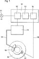
コード化されて伝えられたデータを、対応する信号の受信後に処理すべきときには、送信側でどのようにしてコード化したかについての情報を、受信側で知っていなければならない。それによって、デコーディングを迅速にかつ確実に行うことができる。例えば、コード化方法(例えば2進法、PWM,AM,FM)を受信側で知っていなければならない。コード化されたデータが通常は時間的に連続して伝送されるので、所定のコード化方法、例えば2進信号の場合またはPWM(パルス幅変調)の場合には、コード化の基礎となっている時間基準つまり時定数を知っていなければならない。それによって、受信側で正しくデコードすることができる。1996年12月6日のITT出願“回転速度情報と追加データを伝送する方法と回路装置”により、データを伝える信号を送信側で整形することが知られている。これは車両製造に適用される。特に能動センサから上位の制御装置にデータを伝送するために使用される。このようなシステムが図1に概略的に示してある。車輪106にはセンサ107とブレーキ108が取付けられている。センサ107は“能動”センサである。これは、センサが入って来る電気信号(電圧または電流)を変更するだけでなく、車輪107の情報を上位の装置101に伝えるために、信号を能動的に整形することを意味する。センサ107は伝送線105を介して装置101に接続されている。この場合、伝送線105は複数の個々の伝送線からなっていてもよい。車輪に関するいろいろな情報がセンサから伝送される。最初に、車輪速度に関する情報が伝送される。更に、他の情報、例えば温度、ブレーキパッド摩耗等を伝送することができる。センサ107が車輪上に直接設けられ、比較的に“きびしい”環境(振動、温度差、湿度)にあり、できるだけ故障しないように配線を簡単にすべきであるので、データ伝送方法は、上述の不利な環境にもかかわらず確実に機能しなければならない。
【0003】
図1のシステムは、制御または調整装置101内に、データをコード化して伝送する受信信号をデコードするための本発明に従って形成された装置104を備えている。この装置に続いてデコーダ103と制御システム102が設けられている。この制御システムは受信した信号(図示していない他の入力信号を含む)に応じて、一方では車輪のための制御データを生じ、他方では他のデータ、例えばアラーム装置111用のアラーム等を発生する。制御システム102は電気的な制御信号をブレーキ制御装置110に供給し、このブレーキ制御装置は液圧管路109を介して車輪ブレーキ108に作用する。
【0004】
能動センサ107で発生し、伝送線105を経て本発明による装置104に伝送された信号は、上述のITT出願に記載されているように整形可能である。図3を参照して、個々のデータ経過について説明する。図3のaは理想の経過を示し、図3のb〜dは実際の経過を示している。センサ107によって発生した信号はいろいろなパルス、すなわち車輪パルス301とそれに続くデータパルス303を備えている。車輪パルス301は好ましくは、データパルス303よりも大きな振幅を有する。車輪パルス301とデータパルス303は周期的に連続する。車輪回転速度は連続する車輪パルスの間隔から検出可能である。連続する車輪パルス301の間で、適当な数のデータパルス303が伝送される。このデータパルスによって、他の情報、例えばコード化2進信号が、車輪から本発明による装置に伝送可能である。
【0005】
車輪が停止し、それによって回転数が零であるときに、車輪パルス301は補助パルス304によって置き換えられる。補助パルス304は好ましくは車輪パルス301よりも低い振幅を有し、特にデータパルス303の振幅と同じである。それによって、補助パルスは車輪パルス301と区別することができる。補助パルス304が同期しないで“無から”発生し、データパルス303が直接続いて送信されることにより、補助パルス304はデータパルス303と区別可能である。
【0006】
高い回転速度の場合、図3のcに示す状態が発生する。この場合、データパルス303′の伝送がまだ終了していない時点で新しい車輪パルス301′が発生する。これは、車輪パルス301,301′に関して無害である。なぜなら、この車輪パルスがその高い振幅に基づいて検出可能であるからである。それによって、回転速度情報が伝送される。図3のcの場合、パルス300,303′によるデータの使用または評価を中断することができる。車輪停止状態では、図3のcの状態は発生しない。なぜなら、補助パルス304の間の間隔が自由に選択可能であるので、2つの補助パルス304の間ですべてのデータパルス303を伝送できるように、補助パルスの間隔が選定されるからである。
【0007】
図3には2進データ伝送が示してある。データパルス303はそれぞれ、1または0のビットである。実体を明らかにするためにのみ、データパルスはそれぞれ1として示してある。ビットは所定の時間間隔tpをおいて互いに連続する。ビットは評価およびデコーディングのために、受信側でサンプリングしなければならないので、ビットのそれぞれの値は知られている。従って、データのコード化のためにどのような時間基準つまり時定数が用いられているかを受信側で知っていなければならない。これは、上述のように、トランスミッタがきびしい雰囲気内で使用され、環境の影響が変化することにより、コード化を行う時間基準つまり時定数がシフトされるときに問題である。この場合、時間基準つまり時定数が一定であると仮定することができない。それどころか、時間基準つまり時定数が変化するので、その都度時間基準つまり時定数をトランスミッタに通知しなければならない。
【0008】
上記の問題は車両製造での用途に基づいて説明した。しかし、他の用途でも生じる。
【0009】
本発明の課題は、伝送されたデータを確実にデコードすることができる、データをコード化して伝送する受信信号をデコードするための方法と装置を提供することである。
【0010】
この課題は、データをコード化して伝送する受信信号をデコードする方法において、当該受信信号を、車輪の能動センサ107から送信し、この受信信号は、パルス列であり、このパルス列の第1パルスが、車輪回転速度を測定するために使用される1つの車輪パルス301又は車輪停止時の1つの補助パルス304であり、前記パルス列のその他のパルス303が、コード化したその他のデータを伝送するために使用されるデータパルスであり、前記補助パルス304は、前記車輪パルス301と異なる振幅を有し且つ前記車輪パルス301と同じ持続期間を有し、装置104が、前記能動センサ107によって設定される前記第1パルスの持続期間を1つの時間基準tp;tmとして決定し、前記装置104が、前記パルス列をこの時間基準tp;tmでサンプリングし、当該パルス列をデコーダ103に送信すること、及び、データをコード化して伝送する受信信号をデコードする装置において、当該受信信号は、車輪の能動センサ107から送信され、この受信信号は、パルス列であり、このパルス列の第1パルスが、車輪回転速度を測定するために使用される1つの車輪パルス301又は車輪停止時の1つの補助パルス304であり、前記パルス列のその他のパルス303が、コード化したその他のデータを伝送するために使用されるデータパルスであり、前記補助パルス304は、前記車輪パルス301と異なる振幅を有し且つ前記車輪パルス301と同じ持続期間を有し、装置104が、前記能動センサ107によって設定される前記第1パルスの持続期間を1つの時間基準tp;tmとして決定し、前記装置104が、前記パルス列をこの時間基準tp;tmでサンプリングし、当該パルス列をデコーダ103に送信することによって解決される。従属請求項は本発明の好ましい実施形を示している。
【0011】
本発明では、データをコード化する基礎となる時間基準つまり時定数に関する情報が、伝送されるデータによって伝えられる。時間基準つまり時定数に関するこの情報は受信側で確認され、それに応じて、受信データの他の評価が行われる。当該時間基準つまり時定数に関する情報の伝達は好ましくは、データ伝送の開始時に行われる。当該時間基準つまり時定数に関する情報は評価の開始時に決定することができるので、その都度最も新しい情報が後続のデータの評価のために使用可能である。パルス列が“しばしば”繰り返されるときには、前のサイクルで得られた時間基準つまり時定数に関する情報が、次のサイクルのためにも使用可能である。得られた時間基準つまり時定数は例えば受信信号のビット時間に一致するかまたは2進コード化されているときに例えば比例関係によって、ビット時間から少なくとも推測することができる。パルス幅変調の場合には、得られた時間基準つまり時定数は平均のパルス持続期間等を示すことができる。
【0012】
図2は、データをコード化して伝送する受信信号をデコードするための装置の本発明による実施の形態を示している。この装置は伝送線105を経て信号を受信する。この信号は場合によっては、いろいろな構成要素201,202,203に供給することができる。202は上記の時間基準つまり時定数を決定するための決定装置である。伝送線105を経て入って来る信号に基づいて、決定装置202は時間基準つまり時定数を決定し、必要であれば、他の構成要素に通知する。201は伝送線105を経て受信した信号を評価する評価装置である。この評価は、本願では予備評価または調整であると理解すべきである。例えば、2進コード化信号のための評価装置201は例えば、受信した信号を周期的に抽出するサンプリング装置である。サンプリング(読み取りまたは検知)の周期時間は、決定装置202によって決定された時間基準つまり時定数に応じて設定される。これと似たことを例えばパルス幅変調で行うことができる。203は入ってくる信号の振幅を検査し、閾値に応じて分類する認識装置である。
【0013】
図6は、閾値が認識装置203によってどのようにして使用されるかを概略的に示している。その際、図示した例では、いろいろなパルスが異なる電流値によって示してある。電流値が第1の閾値IS1と第2の閾値IS2にあるときには、補助パルス304またはデータパルス303が認識される。電流値が第2の閾値IS2よりも上にあるときは、車輪パルスが認識される。電流が第2の閾値よりも高い第3の閾値IS3の上にあるときには、エラーが推測される。第1の閾値IS1の下方にある電流値はパルスと認められない。場合によっては能動センサ107にエネルギーを供給する基本周波数電流IL である。従って、検出装置203は入って来る信号を分類し、決定装置202と評価装置201に適当な情報を送る。そして、評価装置201は、場合によっては緩衝して、振幅とパルス周波数を他のシステム要求に適合させたデジタル信号を発生する。この信号は伝送線204を経て後続の構成要素に出力される。この構成要素は信号をデコードし、更に処理することができる。
【0014】
図4は具体的な実施の形態を示している。この実施の形態では特に、“状態機械”の構想を実現している。図4の回路を説明する前に、図5を参照して状態機械の作用を説明する。
【0015】
車輪パルス301,304が入って来る前に、回路は静止状態500(状態0)にある。回路はデータを受信せず、特別な手段を実施しない。立ち上がりエッジが検出されや否や(なぜなら電流が第1の閾値IS1を上回るからである)、回路は状態2(502)に移行する。この状態では、補助パルス304の測定が開始される。更に、第2の閾値IS2を上回ると、状態1(501)に移行する。この状態では、車輪パルス301のパルス幅が測定される。更に、第2の閾値IS2を上回ることとは別に、第1の閾値IS1を上回ることが検出されないほど、レベルの上昇が速い場合がある。そのときは、状態0(500)から状態1(501)に直接移行する。第1の閾値を再び下回ると、状態3(503)に移行する。この状態3では、受け取ったデータパルス304の処理が開始される。これが終了すると、再び状態0(500)に戻る。従って、状態の移行は実質的に閾値決定に応じて生じる。
【0016】
時間基準つまり時定数は好ましくは、パルス、特に受信したパルス列の第1のパルスの幅を測定することによって決定される。そして、送信側で、第1のパルスが、時間基準つまり時定数の目安として使用できるように形成および送信される。これは図3に示したパルス列と良好に調和する。なぜなら、そこでは第1のパルスを質的にのみ検出すればよく、従ってそのパルス持続期間が差し当たって決定められないので、パルス持続期間が時間基準つまり時定数を送信するために使用可能であるからである。図3のaは理想的な方形の形の場合を示している。パルス幅tpは例えば、パルスが高いレベルにある状態を数えることによって得られる。図3のb〜dは有限の急峻のエッジを有する実際のパルス形状を示している。いろいろなパルス(アイドル=302;データパルスまたは補助パルス=303,304;車輪パルス=301;エラー)を異なる閾値IS1,IS2,IS3によって互いに区別することができる。実際のパルスの測定は、閾値を上回るときに測定を開始し、他の閾値を下回るときに測定を終了するように行うことが可能である。補助パルスの測定は好ましくは、休止レベルに対して補助パルスレベルを区別する閾値IS1を上回るときに開始される。車輪パルスの測定は好ましくは、車輪パルスに対して補助パルスを区別する閾値IS2を上回るときに開始される。第1のパルスのパルス幅の測定は好ましくは、休止状態に対して補助パルスを区別する閾値IS1を下回るときに終了する。この場合、車輪パルスまたは補助パルス301,304の終了と第1のデータパルス303の間に非常に低い電流レベル302が位置するように、信号が形成されていることから出発する。
【0017】
図4の回路は装置104と認識装置203を一層正確に示している。認識装置は4つの異なるレベルの4つの出力を有する。この場合、図3に基づいて説明したようなパルス形状(パルス整形)を適用することができる。401は“状態機械”である。この状態機械は認識装置203から関連するレベル信号を受け取り、特にこのレベル信号の変化に応じて個々の回路要素を作動させる。それによって、確実な評価結果が得られる。状態0(500)においてIs1を超える電流上昇が認識されると、伝送線の状態2がロジカル1にセットされ、補助パルス304の幅を測定するために、カウンタ404がスタートする。この場合、カウンタはオシレータ405のクロックパルスを数える。電流が閾値Is2を超えて上昇すると、評価が状態1(501)に変わるので、対応する伝送線がロジカル1にセットされる。カウンタ404は車輪パルス301の幅を測定するために、リセットされて新たにスタートする。カウンタは電流が第1の閾値Is1よりも低下するときに、計数を停止する。
【0018】
(状態2において)補助パルスまたは(状態1において)車輪パルスが測定された後で、状態3に移行する。この状態3では、受け取った時間基準つまり時定数に応じて、そして特にカウンタ404の計数に応じて、データパルスの順次サンプリングが行われる。カウンタ406は常にカウンタ404の計数まで(あるいはこのカウンタ404の計数に応じて得られる値まで)作動する。両カウンタの計数が等しくなると、受信信号がサンプリングされ、得られた値がデジタルの0の値または1の値として使用される。そして、カウンタ406がリセットされ、新たにスタートする。サンプリングは、読み取るデータがもはやないことを他の判断基準によって確かめられるまで行われる。読み取るべきデータ量に関する判断は好ましくは、送信すべきデータ量に関するトランスミッタの判断と同じ基準で行われる。そして、再び状態0に移行し、次のパルスを待つ。
【0019】
図4の評価回路では、カウンタ407,408とレジスタメモリ409は判断基準を実施するために役立つ。ロジック411では、計算された数のデータビットが読み取られているかどうかをチェックする。
【0020】
図4の回路はデータレジスタ412を備えている。このデータレジスタでは、読み取られたデータが緩衝される。回路は更に、妥当ビットのためのレジスタ413を備えている。このレジスタでは、例えば図3のcの303′に対応するビットを妥当でないとして印し付けできるようにするめに、個々のデータに割り当てられた妥当ビットが記憶される。レジスタ412,413の手前には、適当なシフトレジスタ414,415が接続配置可能である。
【0021】
図2,4の実施の形態は特に、図3のaの信号形状(理想的な信号)のために適している。この信号形状の場合、送信側において、車輪パルスまたは補助パルスのパルス幅の一部に相当するパルス休止302が、車輪パルス301(または補助パルス304)の間に挿入される。この場合、休止は好ましくはパルス幅の約50%である。車輪パルスまたは補助パルスに続いて、そのパルス幅tpは、それに続く個々のビットをサンプリングするための周期時間として直接使用可能である。理想的な場合には、ビットのそれぞれの時間的中央点で、ビット毎にサンプリングが行われる。
【0022】
しかし、一方では電気的な値の上昇時間が有限であり、他方では実際の振幅と決定または測定に関与する閾値が変化するので、この変化によって時間基準つまり時定数の測定も不正確になり得る。更に、時間的に連続する多数のビットからなるデジタル信号をサンプリングする際に、時間基準つまり時定数の測定に(たとえ小さくても)エラーが蓄積することを考慮すべきである。なぜなら、エラーは統計的に分配されないで、常に同じ方向に作用するからである。例えば、2%のエラーは25ビットのサンプリングの後で、半分のビット幅だけサンプリング時点をずらすことになる。
【0023】
上記の変形は図6に示してある。閾値IS1,IS2は、IS1max,IS1min,IS2max,IS2minまで変化し得る。これと同じことが、各々の電流レベルIR,IH,D,ILについても当てはまる。
【0024】
それによって、どの位のビットを確実に伝送または評価することができるかについて決定するために、振幅と時間の不正確さを考慮に入れた考え方を用いることができる。この考え方は特に、パルスのエッジ急峻(電流パルスの場合の寸法A/s)を考慮に入れて決定することができる。例えば次の関係が当てはまる。この場合、1つの車輪パルスまたは補助パルスの後の8個のビットの伝送から出発する。
【0025】
【数1】
![]()
【0026】
【数2】
![]()
tm=tp−t1+t2
ここで、tmは測定されたパルス持続期間、すなわち車輪パルスの持続期間である。
【0027】
【数3】
![]()
【数4】

【数5】
![]()
【数6】
![]()
【0031】
本発明による信号整形は好ましくは、車輪パルス301が補助パルス304よりも大きな振幅を有し、ほぼ同じ持続期間tmを有するように行われる。更に、データパルス303は好ましくはこの持続期間tmを有する。この場合、第1のデータパルス303の時間的な中心は車輪パルスまたは補助パルス301,304のパルス幅だけ、このパルスの端(最も低い値または電流が対応する閾値を下回るとき)からほぼ離隔されている。
図3に基づいて、2進データを振幅、特に電流振幅によってコード化するコード化システムについて説明した。しかし、本発明による装置と方法は、観察時間内にエッジが存在することによってあるいは存在しないことによって2進データをコード化することができる伝送システムにも適している。この場合にも、コード化のために、時間基準つまり時定数が使用される。この時間基準つまり時定数は、データ伝送の開始時に車輪パルスまたは補助パルスの持続期間によって受信器に伝えられ、そして受信器で信号の処理のために使用可能である。
【図面の簡単な説明】
【図1】 アクティブ車輪センサから上位の制御装置に伝送するシステムを概略的に示す。
【図2】 データをコード化して伝送する受信信号をデコードするための装置の本発明による実施の形態を示す。
【図3】 a,b,c,dは能動センサで発生し、伝送線を経て本発明による装置に伝送されるいろいろな信号の経過を示す。
【図4】 本発明の具体的な回路を示す図である。
【図5】 状態機械を示す図である。
【図6】 閾値が検出装置によってどのようにして使用されるかを概略的に示す図である。[0001]
The present invention relates to a method and an apparatus for decoding a received signal for encoding and transmitting data as described in the superordinate concept of the independent claims.
[0002]
When the coded and transmitted data is to be processed after receiving the corresponding signal, the receiving side must know information about how it was coded. Thereby, decoding can be performed quickly and reliably. For example, the receiving side must know the encoding method (eg binary , PWM, AM, FM). Since the coded data is usually transmitted continuously in time, in the case of a predetermined coding method, for example in the case of a binary signal or PWM (pulse width modulation), it is the basis for the coding. You must know the time base, that is, the time constant . As a result, it can be correctly decoded on the receiving side. It is known that a signal for transmitting data is shaped on the transmission side by the ITT application “Method and circuit device for transmitting rotational speed information and additional data” filed on Dec. 6, 1996. This applies to vehicle manufacturing. In particular, it is used to transmit data from an active sensor to a host control device. Such a system is shown schematically in FIG. A
[0003]
The system of FIG. 1 includes a
[0004]
The signal generated by the
[0005]
The
[0006]
In the case of a high rotational speed, the state shown in FIG. In this case, a new wheel pulse 301 'is generated when the transmission of the data pulse 303' has not yet been completed. This is harmless with respect to the
[0007]
FIG. 3 shows binary data transmission. Each
[0008]
The above problem has been described based on its use in vehicle manufacturing. However, it occurs in other applications.
[0009]
An object of the present invention is to provide a method and apparatus for decoding a received signal transmitted by encoding data, which can reliably decode transmitted data .
[0010]
The problem is that in a method of decoding a received signal transmitted by encoding data, the received signal is transmitted from the
[0011]
In the present invention, the information on the time reference, ie, the time constant, which is the basis for encoding the data is conveyed by the transmitted data. This information about the time reference, ie time constant, is confirmed at the receiving end and other evaluations of the received data are performed accordingly. The transmission of information about the time reference, ie time constant, is preferably done at the start of data transmission. Since the information about the time reference, ie the time constant, can be determined at the start of the evaluation, each time the newest information can be used for the evaluation of subsequent data. When the pulse train is "often" the repeated information on the time reference, i.e. time constant obtained in the previous cycle, can also be used in order was the next cycle. The obtained time reference or time constant can be at least inferred from the bit time, for example by means of a proportional relationship, for example when it coincides with the bit time of the received signal or is binary coded. In the case of pulse width modulation, resulting time reference, that time constant can show the average of the pulse duration and the like.
[0012]
FIG. 2 shows an embodiment according to the present invention of an apparatus for decoding a received signal for encoding and transmitting data . This apparatus receives a signal via a
[0013]
FIG. 6 schematically shows how the threshold is used by the
[0014]
FIG. 4 shows a specific embodiment. In this embodiment, in particular, the concept of “state machine” is realized. Before describing the circuit of FIG. 4, the operation of the state machine will be described with reference to FIG.
[0015]
Before the
[0016]
The time reference or time constant is preferably determined by measuring the width of the pulse, in particular the first pulse of the received pulse train. Then, on the transmitting side, the first pulse is formed and transmitted so that it can be used as a time reference, that is, a time constant. This is in good harmony with the pulse train shown in FIG. This is because, where it is sufficient only detected qualitatively a first pulse, hence can not be determined determined for the moment the pulse duration, can be used for the pulse duration to send a time reference, that time constant Because there is. FIG. 3a shows the case of an ideal square shape. The pulse width tp is obtained, for example, by counting the state where the pulse is at a high level. 3b to 3d show actual pulse shapes having finite steep edges. Various pulses (idle = 302; data pulse or auxiliary pulse = 303, 304; wheel pulse = 301; error) can be distinguished from each other by different threshold values I S1 , I S2 , I S3 . The actual measurement of the pulse can be performed such that the measurement starts when the threshold value is exceeded and the measurement is ended when the threshold value falls below another threshold value. The measurement of the auxiliary pulse is preferably started when a threshold value I S1 is distinguished that distinguishes the auxiliary pulse level from the rest level. The measurement of the wheel pulse is preferably initiated when a threshold value I S2 is distinguished that distinguishes the auxiliary pulse from the wheel pulse. The measurement of the pulse width of the first pulse preferably ends when it falls below a threshold value I S1 that distinguishes the auxiliary pulse from the resting state. In this case, it begins with the signal being formed such that a very low
[0017]
The circuit of FIG. 4 shows the
[0018]
After an auxiliary pulse (in state 2) or a wheel pulse (in state 1) has been measured,
[0019]
In the evaluation circuit of FIG. 4, the
[0020]
The circuit in FIG. 4 includes a
[0021]
The embodiment of FIGS. 2 and 4 is particularly suitable for the signal shape (ideal signal) of FIG. In the case of this signal shape, on the transmission side, a
[0022]
However, on the one hand, the rise time of the electrical value is finite, and on the other hand, the actual amplitude and the threshold involved in the determination or measurement change, so this change can also make the time reference or time constant measurement inaccurate. . Furthermore, when sampling a digital signal consisting of a large number of consecutive bits in time, it should be taken into account that an error accumulates (even if small) in the measurement of the time reference, ie the time constant. This is because errors are not statistically distributed and always act in the same direction. For example, an error of 2% would shift the sampling time by half the bit width after 25 bits of sampling.
[0023]
The above variant is shown in FIG. Threshold I S1, I S2 is, I S1max, I S1min, I S2max, may vary from I S2min. The same is true for each current level I R , I H, D , I L.
[0024]
Thereby, an idea that takes into account amplitude and time inaccuracies can be used to determine how many bits can be reliably transmitted or evaluated. This idea can be determined in particular taking into account the steep edge of the pulse (dimension A / s in the case of current pulses). For example, the following relationship applies: In this case, we start with the transmission of 8 bits after one wheel pulse or auxiliary pulse.
[0025]
[Expression 1]
![]()
[0026]
[Expression 2]
![]()
tm = tp−t1 + t2
Here, tm the measured pulse duration, i.e., the duration of the wheel pulse.
[0027]
[Equation 3]
![]()
[Expression 4]
[Equation 5]
![]()
[Formula 6]
![]()
[0031]
Preferably the signal shaping by the present invention has a greater amplitude than the
Based on FIG. 3, a coding system for coding binary data by amplitude, in particular current amplitude, has been described. However, the apparatus and method according to the invention are also suitable for transmission systems that can code binary data with or without the presence of an edge within the observation time. Again , a time reference or time constant is used for encoding. The time reference, that time constant is transmitted at the start of data transmission to the receiver by the duration of the wheel pulse or auxiliary pulse, and can be used for processing the signal at the receiver.
[Brief description of the drawings]
FIG. 1 schematically shows a system for transmitting from an active wheel sensor to a host control device.
FIG. 2 shows an embodiment according to the present invention of an apparatus for decoding a received signal for encoding and transmitting data .
FIG. 3 a, b, c, d show the course of various signals generated by active sensors and transmitted over the transmission line to the device according to the invention.
FIG. 4 is a diagram showing a specific circuit of the present invention.
FIG. 5 shows a state machine.
FIG. 6 schematically shows how a threshold is used by a detection device.
Claims (18)
当該受信信号を、車輪の能動センサ(107)から送信し、この受信信号は、パルス列であり、このパルス列の第1パルスが、車輪回転速度を測定するために使用される1つの車輪パルス(301)又は車輪停止時の1つの補助パルス(304)であり、前記パルス列のその他のパルス(303)が、コード化したその他のデータを伝送するために使用されるデータパルスであり、前記補助パルス(304)は、前記車輪パルス(301)と異なる振幅を有し且つ前記車輪パルス(301)と同じ持続期間を有し、
装置(104)が、前記能動センサ(107)によって設定される前記第1パルスの持続期間を1つの時間基準(tp;tm)として決定し、
前記装置(104)が、前記パルス列をこの時間基準(tp;tm)でサンプリングし、当該パルス列をデコーダ(103)に送信することを特徴とする方法。In a method of decoding a received signal that encodes and transmits data,
The received signal is transmitted from the wheel active sensor (107) , and this received signal is a pulse train, and the first pulse of this pulse train is one wheel pulse (301) used to measure the wheel rotation speed. ) Or one auxiliary pulse (304) when the wheel is stopped , and the other pulse (303) of the pulse train is a data pulse used to transmit other encoded data, the auxiliary pulse ( 304) has a different amplitude the wheel pulse (301) and has the same duration as the wheel pulse (301),
A device (104) determines the duration of the first pulse set by the active sensor (107) as one time reference (tp; tm);
The device (104) samples the pulse train with this time reference (tp; tm) and sends the pulse train to the decoder (103) .
当該受信信号は、車輪の能動センサ(107)から送信され、この受信信号は、パルス列であり、このパルス列の第1パルスが、車輪回転速度を測定するために使用される1つの車輪パルス(301)又は車輪停止時の1つの補助パルス(304)であり、前記パルス列のその他のパルス(303)が、コード化したその他のデータを伝送するために使用されるデータパルスであり、前記補助パルス(304)は、前記車輪パルス(301)と異なる振幅を有し且つ前記車輪パルス(301)と同じ持続期間を有し、
装置(104)が、前記能動センサ(107)によって設定される前記第1パルスの持続期間を1つの時間基準(tp;tm)として決定し、
前記装置(104)が、前記パルス列をこの時間基準(tp;tm)でサンプリングし、当該パルス列をデコーダ(103)に送信することを特徴とする装置。In a device that decodes a received signal that encodes and transmits data,
The received signal is transmitted from the active sensor (107) of the wheel, the received signal is a pulse train, the first pulse of the pulse train, one wheel pulse used to measure the wheel rotational speed (301 ) Or one auxiliary pulse (304) when the wheel is stopped , and the other pulse (303) of the pulse train is a data pulse used to transmit other encoded data, the auxiliary pulse ( 304) has a different amplitude the wheel pulse (301) and has the same duration as the wheel pulse (301),
A device (104) determines the duration of the first pulse set by the active sensor (107) as one time reference (tp; tm);
The device (104) samples the pulse train with this time reference (tp; tm) and transmits the pulse train to the decoder (103) .
Applications Claiming Priority (5)
| Application Number | Priority Date | Filing Date | Title |
|---|---|---|---|
| DE19752063 | 1997-11-25 | ||
| DE19752063.4 | 1997-11-25 | ||
| DE19808575A DE19808575A1 (en) | 1997-11-25 | 1998-02-28 | Signal processing method for encoded data |
| DE19808575.3 | 1998-02-28 | ||
| PCT/EP1998/007169 WO1999027675A1 (en) | 1997-11-25 | 1998-11-10 | Method and device for preprocessing a received, data coded transmitting signal |
Publications (3)
| Publication Number | Publication Date |
|---|---|
| JP2001524726A JP2001524726A (en) | 2001-12-04 |
| JP2001524726A5 JP2001524726A5 (en) | 2010-09-16 |
| JP4859272B2 true JP4859272B2 (en) | 2012-01-25 |
Family
ID=7849687
Family Applications (1)
| Application Number | Title | Priority Date | Filing Date |
|---|---|---|---|
| JP2000522698A Expired - Fee Related JP4859272B2 (en) | 1997-11-25 | 1998-11-10 | Method and apparatus for decoding received signals for encoding and transmitting data |
Country Status (2)
| Country | Link |
|---|---|
| JP (1) | JP4859272B2 (en) |
| DE (2) | DE19808575A1 (en) |
Families Citing this family (2)
| Publication number | Priority date | Publication date | Assignee | Title |
|---|---|---|---|---|
| DE19849408A1 (en) | 1998-10-27 | 2000-05-04 | Continental Teves Ag & Co Ohg | Method and device for processing a received signal that transmits data in coded form |
| JP4605435B2 (en) * | 2004-03-24 | 2011-01-05 | アイシン精機株式会社 | Rotation detector |
Citations (10)
| Publication number | Priority date | Publication date | Assignee | Title |
|---|---|---|---|---|
| US4227181A (en) * | 1977-10-12 | 1980-10-07 | Ford Motor Company | Peripheral station in an information handling system |
| GB2180712A (en) * | 1985-09-18 | 1987-04-01 | Plessey Co Plc | Optical coded data transmission system |
| JPS62245832A (en) * | 1986-04-18 | 1987-10-27 | Oki Electric Ind Co Ltd | Clock extraction circuit for digital transmission |
| JPH01194548A (en) * | 1988-01-28 | 1989-08-04 | Fujitsu Ltd | Speed setting system for start-stop synchronizing type data transmission |
| JPH0298529A (en) * | 1988-06-29 | 1990-04-10 | Asahi Chem Ind Co Ltd | Manufacture of package using stretch wrapping film |
| GB2240241A (en) * | 1990-01-18 | 1991-07-24 | Plessey Co Plc | Data transmission systems |
| US5412698A (en) * | 1993-03-16 | 1995-05-02 | Apple Computer, Inc. | Adaptive data separator |
| JPH07264250A (en) * | 1994-03-17 | 1995-10-13 | Nissan Motor Co Ltd | Serial data transmitter |
| FR2725091A1 (en) * | 1994-09-28 | 1996-03-29 | Valeo Electronique | Digital data transmission synchronisation method e.g. for vehicle door remote control |
| JP2001505691A (en) * | 1996-12-07 | 2001-04-24 | コンティネンタル・テーベス・アクチェンゲゼルシャフト・ウント・コンパニー・オッフェネ・ハンデルスゲゼルシャフト | Method and circuit device for transmitting rotation speed information and additional data |
-
1998
- 1998-02-28 DE DE19808575A patent/DE19808575A1/en not_active Withdrawn
- 1998-11-10 JP JP2000522698A patent/JP4859272B2/en not_active Expired - Fee Related
- 1998-11-10 DE DE59803564T patent/DE59803564D1/en not_active Expired - Lifetime
Patent Citations (10)
| Publication number | Priority date | Publication date | Assignee | Title |
|---|---|---|---|---|
| US4227181A (en) * | 1977-10-12 | 1980-10-07 | Ford Motor Company | Peripheral station in an information handling system |
| GB2180712A (en) * | 1985-09-18 | 1987-04-01 | Plessey Co Plc | Optical coded data transmission system |
| JPS62245832A (en) * | 1986-04-18 | 1987-10-27 | Oki Electric Ind Co Ltd | Clock extraction circuit for digital transmission |
| JPH01194548A (en) * | 1988-01-28 | 1989-08-04 | Fujitsu Ltd | Speed setting system for start-stop synchronizing type data transmission |
| JPH0298529A (en) * | 1988-06-29 | 1990-04-10 | Asahi Chem Ind Co Ltd | Manufacture of package using stretch wrapping film |
| GB2240241A (en) * | 1990-01-18 | 1991-07-24 | Plessey Co Plc | Data transmission systems |
| US5412698A (en) * | 1993-03-16 | 1995-05-02 | Apple Computer, Inc. | Adaptive data separator |
| JPH07264250A (en) * | 1994-03-17 | 1995-10-13 | Nissan Motor Co Ltd | Serial data transmitter |
| FR2725091A1 (en) * | 1994-09-28 | 1996-03-29 | Valeo Electronique | Digital data transmission synchronisation method e.g. for vehicle door remote control |
| JP2001505691A (en) * | 1996-12-07 | 2001-04-24 | コンティネンタル・テーベス・アクチェンゲゼルシャフト・ウント・コンパニー・オッフェネ・ハンデルスゲゼルシャフト | Method and circuit device for transmitting rotation speed information and additional data |
Also Published As
| Publication number | Publication date |
|---|---|
| JP2001524726A (en) | 2001-12-04 |
| DE59803564D1 (en) | 2002-05-02 |
| DE19808575A1 (en) | 1999-05-27 |
Similar Documents
| Publication | Publication Date | Title |
|---|---|---|
| US6542847B1 (en) | Sensor system for detecting movements | |
| JP3958339B2 (en) | Pulse modulation method | |
| KR850008072A (en) | High Speed Digital Loop Transceiver | |
| JP4541553B2 (en) | Method and apparatus for processing a received signal carrying encoded data | |
| CN108254586B (en) | Apparatus for encoding and decoding wheel speed sensor signal and method for transmitting encoded wheel speed sensor signal | |
| JP4859272B2 (en) | Method and apparatus for decoding received signals for encoding and transmitting data | |
| JP7407950B2 (en) | Distributed fiber optic sensing using point sensors | |
| US6326778B1 (en) | Method and apparatus for transmitting speed information and other additional information detected by a sensing device | |
| EP1168741A3 (en) | Determination of a discrimination threshold in an optical transmission system | |
| JPH0823310A (en) | Optical signal transmitter | |
| US6731224B1 (en) | Method and device for preprocessing a received, data coded transmitting signal | |
| JPH0918461A (en) | Data receiver | |
| JP4677579B2 (en) | Signal transmission device | |
| JPH03504554A (en) | How to determine signal reception time by correlation technique | |
| JPH04287423A (en) | Data demodulation circuit | |
| JP4213868B2 (en) | Digital transmission method | |
| JP3531797B2 (en) | Encoder receiving circuit | |
| JP3204787B2 (en) | Detection circuit | |
| KR100526938B1 (en) | Method for receiving differential code at micom | |
| JP3487004B2 (en) | Moving object identification device | |
| JP2006128800A (en) | One-wire data communication method, and one-wire data transmitter/receiver employing that communication method | |
| JPH08331023A (en) | Identification system | |
| JP5704506B2 (en) | Communication device and field device system | |
| JPH0823355A (en) | Transmitter-receiver | |
| JP2745759B2 (en) | Read / write head for article identification system |
Legal Events
| Date | Code | Title | Description |
|---|---|---|---|
| A521 | Written amendment |
Free format text: JAPANESE INTERMEDIATE CODE: A523 Effective date: 20051006 |
|
| A621 | Written request for application examination |
Free format text: JAPANESE INTERMEDIATE CODE: A621 Effective date: 20051006 |
|
| A977 | Report on retrieval |
Free format text: JAPANESE INTERMEDIATE CODE: A971007 Effective date: 20080814 |
|
| A131 | Notification of reasons for refusal |
Free format text: JAPANESE INTERMEDIATE CODE: A131 Effective date: 20080930 |
|
| A601 | Written request for extension of time |
Free format text: JAPANESE INTERMEDIATE CODE: A601 Effective date: 20081224 |
|
| A602 | Written permission of extension of time |
Free format text: JAPANESE INTERMEDIATE CODE: A602 Effective date: 20090107 |
|
| A601 | Written request for extension of time |
Free format text: JAPANESE INTERMEDIATE CODE: A601 Effective date: 20090129 |
|
| A602 | Written permission of extension of time |
Free format text: JAPANESE INTERMEDIATE CODE: A602 Effective date: 20090205 |
|
| A601 | Written request for extension of time |
Free format text: JAPANESE INTERMEDIATE CODE: A601 Effective date: 20090226 |
|
| A602 | Written permission of extension of time |
Free format text: JAPANESE INTERMEDIATE CODE: A602 Effective date: 20090305 |
|
| A521 | Written amendment |
Free format text: JAPANESE INTERMEDIATE CODE: A523 Effective date: 20090326 |
|
| A131 | Notification of reasons for refusal |
Free format text: JAPANESE INTERMEDIATE CODE: A131 Effective date: 20100302 |
|
| RD04 | Notification of resignation of power of attorney |
Free format text: JAPANESE INTERMEDIATE CODE: A7424 Effective date: 20100519 |
|
| A601 | Written request for extension of time |
Free format text: JAPANESE INTERMEDIATE CODE: A601 Effective date: 20100601 |
|
| A602 | Written permission of extension of time |
Free format text: JAPANESE INTERMEDIATE CODE: A602 Effective date: 20100608 |
|
| A601 | Written request for extension of time |
Free format text: JAPANESE INTERMEDIATE CODE: A601 Effective date: 20100630 |
|
| A602 | Written permission of extension of time |
Free format text: JAPANESE INTERMEDIATE CODE: A602 Effective date: 20100707 |
|
| A524 | Written submission of copy of amendment under section 19 (pct) |
Free format text: JAPANESE INTERMEDIATE CODE: A524 Effective date: 20100802 |
|
| TRDD | Decision of grant or rejection written | ||
| A01 | Written decision to grant a patent or to grant a registration (utility model) |
Free format text: JAPANESE INTERMEDIATE CODE: A01 Effective date: 20111004 |
|
| A01 | Written decision to grant a patent or to grant a registration (utility model) |
Free format text: JAPANESE INTERMEDIATE CODE: A01 |
|
| A61 | First payment of annual fees (during grant procedure) |
Free format text: JAPANESE INTERMEDIATE CODE: A61 Effective date: 20111101 |
|
| R150 | Certificate of patent or registration of utility model |
Free format text: JAPANESE INTERMEDIATE CODE: R150 |
|
| FPAY | Renewal fee payment (event date is renewal date of database) |
Free format text: PAYMENT UNTIL: 20141111 Year of fee payment: 3 |
|
| R250 | Receipt of annual fees |
Free format text: JAPANESE INTERMEDIATE CODE: R250 |
|
| LAPS | Cancellation because of no payment of annual fees |