JP4857326B2 - Ophthalmic equipment - Google Patents
Ophthalmic equipment Download PDFInfo
- Publication number
- JP4857326B2 JP4857326B2 JP2008295805A JP2008295805A JP4857326B2 JP 4857326 B2 JP4857326 B2 JP 4857326B2 JP 2008295805 A JP2008295805 A JP 2008295805A JP 2008295805 A JP2008295805 A JP 2008295805A JP 4857326 B2 JP4857326 B2 JP 4857326B2
- Authority
- JP
- Japan
- Prior art keywords
- wavelength
- optical system
- light
- focus
- selection
- Prior art date
- Legal status (The legal status is an assumption and is not a legal conclusion. Google has not performed a legal analysis and makes no representation as to the accuracy of the status listed.)
- Active
Links
Images


Classifications
-
- A—HUMAN NECESSITIES
- A61—MEDICAL OR VETERINARY SCIENCE; HYGIENE
- A61B—DIAGNOSIS; SURGERY; IDENTIFICATION
- A61B3/00—Apparatus for testing the eyes; Instruments for examining the eyes
- A61B3/0008—Apparatus for testing the eyes; Instruments for examining the eyes provided with illuminating means
-
- A—HUMAN NECESSITIES
- A61—MEDICAL OR VETERINARY SCIENCE; HYGIENE
- A61B—DIAGNOSIS; SURGERY; IDENTIFICATION
- A61B3/00—Apparatus for testing the eyes; Instruments for examining the eyes
- A61B3/10—Objective types, i.e. instruments for examining the eyes independent of the patients' perceptions or reactions
- A61B3/12—Objective types, i.e. instruments for examining the eyes independent of the patients' perceptions or reactions for looking at the eye fundus, e.g. ophthalmoscopes
Description
本発明は眼科装置に関し、特に眼科装置の焦点を合わせる技術に関するものである。 The present invention relates to an ophthalmic apparatus, and more particularly to a technique for focusing an ophthalmic apparatus.
複数の照明光源を選択して使用する眼底カメラに関する技術が特許文献1に開示されている。この場合、照明光源が異なると指標光の波長を変えて視認性を高める必要がある。しかし、指標光の波長差から光路長差が生じ、正確な焦点確認ができなくなる。そこで、特許文献1に開示される技術では、照明光源に応じて、照明系リレーレンズを交換することで光路長差を吸収している。
しかしながら、照明系リレーレンズ鏡筒は大きく、光学系の精度を保った状態で入れ替えるのは困難である。 However, the illumination system relay lens barrel is large, and it is difficult to replace it while maintaining the accuracy of the optical system.
本発明はこのような従来技術の課題を鑑みてなされたものであり、照明光源の波長が変更されても焦点合わせが容易である眼科装置を提供することを目的とする。 The present invention has been made in view of such a problem of the prior art, and an object thereof is to provide an ophthalmologic apparatus that can be easily focused even if the wavelength of an illumination light source is changed.
上記の目的を達成するための、本発明の一態様によるによる眼科装置は、以下の構成を備える。すなわち、被検眼を照明する第一の光学系と、
前記第一の光学系を介して照明された前記被検眼眼底像を結像する第二の光学系と、
前記第二の光学系の焦点状態を示す指標光を前記被検眼に投影する指標投影手段と、
前記指標投影手段が投影する指標光の波長を変更する変更手段と、
前記変更手段で変更された指標光の波長に応じて前記指標投影手段の光軸上の位置を制御する位置制御手段と、を有する。
In order to achieve the above object, an ophthalmic apparatus according to one aspect of the present invention comprises the following arrangement. That is, a first optical system that illuminates the eye to be examined;
A second optical system that forms the fundus image of the subject's eye illuminated through the first optical system;
Index projection means for projecting index light indicating the focus state of the second optical system onto the eye to be examined;
Changing means for changing the wavelength of the index light projected by the index projection means;
Position control means for controlling the position of the index projection means on the optical axis in accordance with the wavelength of the index light changed by the change means.
照明光源の波長が変更されても焦点合わせが容易である眼科装置を提供することができる。 It is possible to provide an ophthalmologic apparatus that can be easily focused even if the wavelength of the illumination light source is changed.
[第1の実施形態]
本発明の第一の実施形態である眼科装置を図1乃至図3に基づいて説明する。
[First Embodiment]
The ophthalmologic apparatus which is 1st embodiment of this invention is demonstrated based on FIG. 1 thru | or FIG.
図1は眼科装置の構成を説明する概略構成図である。 FIG. 1 is a schematic configuration diagram illustrating the configuration of an ophthalmologic apparatus.
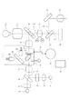
ハロゲンランプ11は、可視の波長の光源であり、被検者の眼底を可視観察する場合に用いられる。キセノンランプ12は、可視の波長の光源であり、被検者の眼底を可視撮影する場合に用いられる。可視リングスリット13は、ハロゲンランプ11、キセノンランプ12からの照明光をリング状の照明形状にするためのマスクである。赤外LED14は、赤外観察する場合の光源である。赤外リングスリット15は、赤外LED14からの照明光をリング状の照明形状にするためのマスクである。照明ミラー16は、ダイクロミラーであり、可視光を反射、赤外光を透過する特性を持っている。照明ミラー16によって可視リング照明と赤外リング照明の光路が合体する。O1は第一の光学系であり光軸を連続線又は点線で示している。第一の光学系O1は、光源が発する光を被検眼22に照明する。照明リレーレンズ17、照明リレーレンズ19によってリング状の照明光は被検眼に結像される。
The
指標投影手段としてのスプリットユニット18は、焦点状態を示す指標光を被検眼22に投影する。波長が異なる指標光を投影するために、波長が異なる光源18a,光源18bとを備える。18cは光源18aが発する光を透過し、光源18bが発する光を反射するダイクロックミラーである。
The
光源18a,光源18bのいずれかが発する光は、スプリットプリズム18dで分割され、スプリットマスク18eによって二本のスプリット像として直線像状の光束として生成される。この光束は指標光として被検眼22に投影される。投影された指標光は眼科装置と被検眼22と焦点が合っている場合には一本の直線状に結像され、合っていない場合には2本の直線状に結像される。本実施形態では、指標光を眼底に投影するが、これに限られず前眼部に投影してもよい。光源18a,光源18bはそれぞれ可視観察、赤外観察での視認性を上げる波長が用いられる。光源としてはLEDが例えば用いられ、以後光源18a,光源18bを可視用LED18a,赤外用LED18bと呼ぶものとする。
Light emitted from either the
そしてスプリットユニット18を観察時に第一の光学系O1に進入し図中矢印方向に光軸上を移動する。これによりフォーカスのための指標光を発する位置を光軸方向に移動させる不図示の機構を有している。この不図示の機構はスプリット駆動モータM1と連動している。また、撮影時に第一の光学系O1から退避させる不図示の機構を有している。スプリット位置検知回路段S1は、スプリットユニット18の位置を検出する。穴明きミラー20は、中心に穴が明いた全反射ミラーであり、リング状の照明光は外周のミラーによって反射され、被検眼眼底像は中央の穴から透過するように構成されている。対物レンズ21は、穴明きミラー20を通ったリング状の照明光で、被検眼22を照明する。被検眼22からの反射光は、対物レンズを通って穴明きミラー20の中心に結像される。第二の光学系O2は被検眼22からの反射光を結像する光学系である。また第二の光学系O2は、観察用の光学系O3と撮影用の光学系O4に光学的に分岐される。観察用の光学系O3はファインダ接眼レンズ26を備え、撮影用の光学系O4は撮像素子からなるセンサ27を備える。
The
被検者眼底像から、ファインダ接眼レンズ26、撮像素子27に至る光軸を連続線で示している。なお、第二の光学系O2は、前眼部、眼底部などの被検眼22のいずれかの部分を結像する。
The optical axis from the subject's fundus image to the
フォーカスレンズ23は、穴明きミラー20の中央の穴を通過した撮影光束の焦点(以下、「フォーカス」と呼ぶ場合もある)調節を行うためのレンズであり、図中矢印方向に移動することで焦点調節を行う。フォーカスレンズ駆動モータM2はフォーカスレンズ23を移動するために用いられ、フォーカスレンズ位置検知回路S2は、フォーカスレンズ23の位置を検出する。可動ミラー24は、可視観察時には図示の通り位置し、撮影光を観察用の光学系O3に導く。また、赤外観察時、および撮影時には図中矢印の通り回動することで退避し、撮影光を撮影用の光学系O4に導く。固定ミラー25は、撮影光をファインダに向けて反射させ、ファインダ接眼レンズ26を通して検者が観察可能とする。撮像素子で構成されるセンサ27は、撮影光を光電変換し、デジタルデータとして不図示のデジタル処理回路によって変換する。デジタルデータは、赤外観察時において不図示の表示器に表示され、撮影時において不図示の記録媒体に記録される。フォーカス調整ノブ28を検者が操作することで、所望のフォーカス状態に調整でき、フォーカス調整検知回路S3にてその位置を検出する。選択手段としての光源選択スイッチ29を検者が選択操作することで、観察光源を可視光または赤外光から選択操作する。これにより被検眼22には、近赤外領域の照明光と可視光領域の照明光とに波長が変更されて照明される。
The focus lens 23 is a lens for adjusting the focus (hereinafter sometimes referred to as “focus”) of the photographing light beam that has passed through the center hole of the
指標投影手段としてのスプリットユニット18に関して、図1及び図2に基づいて詳細を説明する。
The details of the
図2(a),(c)は本発明の第一の実施形態のスプリット光学系の展開図である。スプリットプリズム18dの反射面及び穴明きミラー20といった反射面は省略し、光学系をストレートに展開している。
2A and 2C are development views of the split optical system according to the first embodiment of the present invention. The reflecting surface of the
可視用LED18a、近赤外LED18b、ダイクロミラー18c、スプリットプリズム18d、スプリットマスク18eがそれぞれ図示されている。
可視用LED18aの点灯時、その光束はダイクロミラー18cを透過し、スプリットプリズム18dで分割される。スプリットプリズム18dの至近位置に配置されたスプリットマスク18eによって2本のスプリット像は直線像となる。2本のスプリット像は、照明リレーレンズ19によって穴明きミラー20に結像される。さらに穴明きミラー20で反射された象は対物レンズ21によって被検眼22の眼底に投影される。第二の光学系の焦点が被検眼22の眼底とあっている場合には、分割された二本のスプリット像は図2(b)の様に一直線の状態で投影される。
When the
この状態で点灯するLEDを近赤外用LED18bに切り換えると、LED色の違いによる色収差によって光路長に変化が生じる。近赤外用LED18bが点灯すると、その光束はダイクロミラー18cによって反射し、その後は可視用LED18aと同様の光路を進む。しかし、色収差によって光路長が伸びた結果、被検眼22の眼底よりも遠くに結像することになり、被検眼22の眼底に投影された二本のスプリット像は図2(d)の様に、左右の直線像としてずれを生じる。すなわち、眼科装置の焦点が合っていない場合には、左右の直線像として図2(d)の様にずれが生じる。
When the LED that is lit in this state is switched to the near-
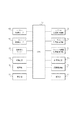
図3は本発明の第一の実施形態を説明するブロック図である。 FIG. 3 is a block diagram for explaining the first embodiment of the present invention.
CPU30は、主として制御部31、変更部32、位置制御部33、警告部34の各構成要素の動作を制御する。不図示のメモリ101は、CPU30が実行する制御プログラムを格納したり、CPU30によるプログラム実行時の作業領域を提供したりする。
The
制御部31、警告部34はセンサ27の撮影動作を制御する。変更部32は可視用LED18a、近赤外用LED18bの点灯を制御することで指標光の波長を変更する。また、位置制御部33はCPU30を介してスプリット駆動モータM1、スプリット位置検知回路S1、フォーカスレンズ駆動モータM2、フォーカスレンズ位置検知回路S2を制御することでフォーカスレンズ23の移動、スプリットユニット18の移動を制御する。また、フォーカス調整位置検知回路S3、光源選択スイッチ29からの出力信号はCPU30を介して、制御部31、変更部32、位置制御部33、警告部34に接続されている。これにより、光源の制御、フォーカスレンズ23の移動、スプリットユニット18の移動を行う。
The
図4は本発明の第一の実施形態を説明するフォーカス動作の流れを示すフローチャートである。 FIG. 4 is a flowchart showing the flow of the focus operation for explaining the first embodiment of the present invention.
(S00)において、CPU30の制御下によりフォーカスシーケンスフローを開始する。
In (S00), the focus sequence flow is started under the control of the
(S01)において、フォーカス調整ノブ28の停止位置をフォーカス調整位置検出手段S3が検知してCPU30に出力する。これにより、検者が設定している焦点位置(フォーカス位置)をCPU30にて認識する。
In (S01), the focus adjustment position detection means S3 detects the stop position of the
(S02)において、光源選択スイッチ29の状態を確認、”VL”で示される可視光観察が選択されていれば(S03)に、”IR”で示される赤外観察が選択されている場合(S04)に進む。 In (S02), the state of the light source selection switch 29 is confirmed. If the visible light observation indicated by “VL” is selected (S03), the infrared observation indicated by “IR” is selected ( Go to S04).
(S03)において、変更部32はスプリット光源に可視用LED18aを選択し、指標光の波長を可視観察用とする。そして、CPU30はメモリ101に記憶されるVLテーブルを読み出す。このVLテーブルには、フォーカス調整位置検出手段S3の出力に対応したスプリットユニット18およびフォーカスレンズ23の停止位置が保存されている。そして(S05)に進む。
In (S03), the changing
(S04)において、変更部32はスプリット光源に赤外用LED18bを選択し、指標光の波長を赤外観察用とする。そして、CPU30はメモリ101に記憶されるIRテーブルを読み出す。このIRテーブルには、フォーカス調整位置検出手段S3の出力に対応したスプリットユニット18およびフォーカスレンズ23の停止位置が保存されている。そして(S05)に進む。
In (S04), the changing
すなわち、S03,S04では変更手段である変更部32が、光源選択スイッチ29で選択された光源の波長に応じて、可視用LED18a、赤外用LED18bのいずれかを発光することで指標光の波長を変更する。
That is, in S03 and S04, the changing
(S05)において、スプリットユニット18、フォーカスレンズ23が移動して間は非合焦状態になる。そこで、制御部31はピンボケ写真を防止するために、レリーズ禁止状態としてセンサ37の撮影動作を禁止する。なお、本実施の形態では“禁止”としているが、レリーズ優先の考え方から“警告”等の制限に留めることも可能である。この場合には、センサ27の撮影動作に対して、警告手段である警告部32が警告を発する。
In (S05), the
(S06)において、読み出されたテーブルの情報に基づいて、位置制御部33がスプリット駆動モータM1を駆動する。そして、位置制御部33の制御下でスプリット位置検知回路S1の出力信号に基づいてスプリットユニット18をテーブルから得た位置に移動する。
In (S06), the position control unit 33 drives the split drive motor M1 based on the read table information. Then, under the control of the position controller 33, the
位置制御部33は、スプリットユニット18が所定の停止位置に到達したかを確認し、到達していなければ(S06)に戻り、到達していれば(S08)に進む。
The position control unit 33 confirms whether the
(S08)、読み出されたテーブルの情報に基づいて、位置制御部33がフォーカスレンズ駆動モータM2を駆動する。そして、位置制御部33の制御下でフォーカスレンズ位置検知回路S2の出力信号に基づいてフォーカスレンズ23をテーブルから得た位置に移動する。 (S08) Based on the read table information, the position controller 33 drives the focus lens drive motor M2. Then, under the control of the position control unit 33, the focus lens 23 is moved to a position obtained from the table based on the output signal of the focus lens position detection circuit S2.
(S09)にてフォーカスレンズ位置検知回路S2の出力を位置制御部33は検出し、フォーカスレンズ23の停止位置を確認、所定の停止位置に到達していなければ(S08)に、到達していれば(S10)に進む。 In (S09), the position control unit 33 detects the output of the focus lens position detection circuit S2, confirms the stop position of the focus lens 23, and if the predetermined stop position has not been reached (S08), the position has been reached. (S10).
(S10)では先ほど禁止したレリーズ動作の禁止解除を制御部31は施し、(S11)に進んで全てのフォーカスシーケンスフローを完了する。
In (S10), the
図5は本発明の第一の実施の形態のフォーカス動作対応図である。図2を用いて説明したスプリット光学系の説明の通り、波長の異なる光源の選択によってフォーカスレンズ24の0Dがシフトする。
FIG. 5 is a view corresponding to the focus operation according to the first embodiment of the present invention. As described in the split optical system described with reference to FIG. 2, 0D of the
本実施の形態ではフォーカス調整ノブ29の位置を基準として、フォーカスレンズ24及びスプリットユニット18を移動している。そのため、0Dの対応を図5のようにシフトする必要がある。合わせて、フォーカスレンズ24及びスプリットユニット18の動作範囲も規制する必要があり、点線で示した範囲は、フォーカスレンズ24及びスプリットユニット18は動作可能であるが、CPU30によって動作制限を加えられる。
In the present embodiment, the
以上の処理の流れに限定されず、可視用LED18a、赤外用LED18bの発光のタイミング、スプリットユニット18の移動のタイミングは同時であっても前後してもよい。また、同様に可視用LED18a、赤外用LED18bの発光のタイミング、フォーカスレンズ24の移動のタイミングは同時であっても前後してもよい。
The flow of the above processing is not limited, and the light emission timing of the
以上の構成により、波長の異なる光源の選択と、フォーカス調整ノブ29の操作と、に応じて、スプリットユニット18及びフォーカスレンズ23を独立して制御することが可能となる。
With the above configuration, the
以上説明した様に、指標光の波長を変えた時に生じる、光路長の変化を修正することが、スプリットユニット18を移動するだけ実現でき、機器の簡素化が図れ信頼性が向上するとともに、小型化も図ることができ使い易いものとすることが可能となる。
As described above, correcting the change in the optical path length that occurs when the wavelength of the index light is changed can be realized only by moving the
また、照明光を切り換えたときに、その照明光に対して視認性の良い指標光に切り換えても、光路長の変化を修正することが、簡単な構成によって実現できる。 Further, when the illumination light is switched, the change in the optical path length can be corrected with a simple configuration even if the illumination light is switched to the index light having good visibility.
また、センサ27の撮影動作を制限することで、像の状態が安定していないときに、画像を記録しなくなるので、撮影の失敗を防ぐことが可能になる。
In addition, by restricting the photographing operation of the
(第二の実施の形態)
本発明の第二の実施の形態の説明を図6に基づいて行う。
(Second embodiment)
The second embodiment of the present invention will be described with reference to FIG.
図6は本発明の第二の実施の形態を説明するための概略構成図である。 FIG. 6 is a schematic configuration diagram for explaining a second embodiment of the present invention.
第一の実施の形態を表した図1と共通の要素に対して同じ番号を振って説明を省略する。新たに追加した要素は機械機構の連動部材35である。連動部材35は、フォーカス調整ノブ28とスプリットユニット18は歯車やレバーといった既知の機械機構にて連動する。これにより、スプリットユニット18を駆動するモータM1、フォーカス調整ノブ29の停止位置を検出するフォーカス調整検知回路S3は不要となっている。この場合、フォーカス調整ノブ28及びフォーカス調整ノブ28と機械機構で連動している部材が位置制御手段となる。
The same elements as those in FIG. 1 showing the first embodiment are assigned the same reference numerals, and description thereof is omitted. The newly added element is the interlocking member 35 of the mechanical mechanism. The interlocking member 35 is interlocked with the
以上の構成により、検者がフォーカス調整ノブ29を操作してフォーカス変更動作を行うと、スプリットユニット18が連動して移動するとともに、スプリットユニット18の停止位置から、光源選択スイッチ29の状態に応じてフォーカスレンズ23の停止位置を制御することが可能となる。
With the above configuration, when the examiner operates the focus adjustment knob 29 to perform the focus changing operation, the
(第三の実施の形態)
本発明の第三の実施の形態の説明を図7に基づいて行う。
(Third embodiment)
The third embodiment of the present invention will be described with reference to FIG.
図7は本発明の第三の実施の形態を説明するための概略構成図である。 FIG. 7 is a schematic configuration diagram for explaining a third embodiment of the present invention.
第一の実施の形態を表した図1と共通の要素に対して同じ番号を振ってあり説明を省略する。新たに追加した要素は機械機構の連動部材31であり、フォーカス調整ノブ28とフォーカスレンズ23は歯車やレバーといった既知の機械機構によって直接連動する。これにより、フォーカスレンズ23を駆動するモータM2、フォーカス調整ノブ29の停止位置を検出するフォーカス調整検知回路S3が不要となる。この場合、フォーカス調整ノブ28及びフォーカス調整ノブ28と機械機構で連動している部材が位置制御手段となる。
The same elements as those in FIG. 1 showing the first embodiment are assigned the same numbers, and the description thereof is omitted. The newly added element is a mechanical
以上の構成により、検者がフォーカス調整ノブ29を操作してフォーカス変更動作を行うと、フォーカスレンズ23が連動して移動するとともに、フォーカスレンズ23の停止位置から、光源選択スイッチ29の状態を鑑みてスプリットユニット18の停止位置を制御することが可能となる。
With the above configuration, when the examiner performs the focus change operation by operating the focus adjustment knob 29, the focus lens 23 moves in conjunction with the stop position of the focus lens 23 and the state of the light source selection switch 29 is considered. Thus, the stop position of the
11 ハロゲンランプ
12 キセノンランプ
14 赤外LED
18 スプリットユニット
18a 可視用LED
18b 赤外用LED
22 被検眼
23 フォーカスレンズ
27 センサ
30 CPU
31 制御部
32 変更部
33 位置制御部
34 警告部
11
18
18b Infrared LED
22 Eye to be examined 23
31
Claims (16)
前記照明光学系を介して照明した前記被検眼からの戻り光をフォーカス手段を介して撮像手段に結像する撮影光学系と、
前記照明光学系を介して前記被検眼に投影するフォーカス指標光の波長を選択する選択手段と、
前記選択手段により選択された波長のフォーカス指標光を前記被検眼に投影する指標投影手段と、
前記選択手段による選択に応じて、該選択された波長に対応する前記照明光学系の光軸上の位置に前記指標投影手段を移動する位置制御手段と、
を有することを特徴とする眼科装置。 Illuminating means for illuminating the eye to be examined via an illumination optical system;
An imaging optical system that forms an image of the return light from the eye to be examined illuminated through the illumination optical system on an imaging unit through a focusing unit;
A selection means for selecting a wavelength of focus index light to be projected onto the eye to be examined via the illumination optical system;
Index projection means for projecting focus index light of the wavelength selected by the selection means onto the eye to be examined;
Position control means for moving the index projection means to a position on the optical axis of the illumination optical system corresponding to the selected wavelength according to the selection by the selection means;
An ophthalmologic apparatus comprising:
前記位置制御手段が、前記記憶手段により記憶されている位置に前記指標投影手段を移動することを特徴とする請求項1あるいは2に記載の眼科装置。 Storage means for storing a position on the optical axis of the illumination optical system corresponding to the wavelength selected by the selection means;
The ophthalmologic apparatus according to claim 1, wherein the position control unit moves the index projection unit to a position stored in the storage unit.
前記位置制御手段が、前記選択手段により選択された波長と前記テーブルとに基づいて取得される該選択された波長に対応する位置に前記指標投影手段を移動することを特徴とする請求項3に記載の眼科装置。 The storage means stores the position on the optical axis of the illumination optical system as a table corresponding to the wavelength of the focus index light;
4. The position control means moves the index projection means to a position corresponding to the selected wavelength acquired based on the wavelength selected by the selection means and the table. The ophthalmic device described.
前記照明光選択手段による選択に応じて、該選択した波長に対応する波長のフォーカス指標光を発生させる指標制御手段と、
を有することを特徴とする請求項1乃至5のいずれか1項に記載の眼科装置。 Illumination light selection means for selecting either the near infrared region or the visible region as the wavelength of illumination light illuminated on the eye to be examined via the illumination optical system;
Index control means for generating focus index light having a wavelength corresponding to the selected wavelength according to the selection by the illumination light selection means;
The ophthalmologic apparatus according to claim 1, wherein the ophthalmologic apparatus is provided.
前記照明光の波長が近赤外領域である場合には前記フォーカス指標光の波長を近赤外領域とし、
前記照明光の波長が可視領域である場合には前記フォーカス指標光の波長を可視領域とすることを特徴とする請求項6に記載の眼科装置。 The index control means is
When the wavelength of the illumination light is in the near infrared region, the wavelength of the focus index light is in the near infrared region,
The ophthalmic apparatus according to claim 6, wherein when the wavelength of the illumination light is in a visible region, the wavelength of the focus index light is in the visible region.
前記選択手段による選択に応じて、該選択された波長に対応する波長のフォーカス指標光を前記被検眼に投影する指標投影手段と、
前記選択手段による選択に応じて、該選択された波長に対応する前記照明光学系の光軸上の位置に前記指標投影手段を移動する位置制御手段と、
を有することを特徴とする眼科装置。 Selection means for selecting the wavelength of illumination light that illuminates the eye to be examined via the illumination optical system;
Index projection means for projecting focus index light having a wavelength corresponding to the selected wavelength onto the eye to be examined in accordance with the selection by the selection means;
Position control means for moving the index projection means to a position on the optical axis of the illumination optical system corresponding to the selected wavelength according to the selection by the selection means;
An ophthalmologic apparatus comprising:
前記選択手段により選択された波長のフォーカス指標光を前記被検眼に投影する指標投影手段と、
前記選択手段による選択に応じて、該選択された波長に対応する前記照明光学系の光軸上の位置に前記指標投影手段を移動する位置制御手段と、
を有することを特徴とする眼科装置。 Selection means for selecting the wavelength of the focus index light to be projected onto the eye to be examined via the illumination optical system;
Index projection means for projecting focus index light of the wavelength selected by the selection means onto the eye to be examined;
Position control means for moving the index projection means to a position on the optical axis of the illumination optical system corresponding to the selected wavelength according to the selection by the selection means;
An ophthalmologic apparatus comprising:
前記位置制御手段は、前記指標投影手段とは独立に前記フォーカス手段を制御して、前記選択手段により選択された波長に対応する前記撮影光学系の光軸上の位置に前記フォーカス手段を移動することを特徴とする請求項10乃至12のいずれか1項に記載の眼科装置。 Have a photographing optical system formed on the imaging means through the focusing means return light from the subject's eye illuminated the focus index light through the illumination optical system,
The position control means controls the focus means independently of the index projection means, and moves the focus means to a position on the optical axis of the photographing optical system corresponding to the wavelength selected by the selection means. the ophthalmic apparatus according to any one of claims 10 to 1 2, characterized in that.
前記位置制御手段が、前記記憶手段により記憶されている位置に前記指標投影手段を移動することを特徴とする請求項10乃至13のいずれか1項に記載の眼科装置。The ophthalmologic apparatus according to claim 10, wherein the position control unit moves the index projection unit to a position stored by the storage unit.
前記選択手段により選択された波長のフォーカス指標光を前記被検眼に投影する指標投影手段と、Index projection means for projecting focus index light of the wavelength selected by the selection means onto the eye to be examined;
前記選択手段による選択に応じて、該選択された波長に対応する前記照明光学系の光軸上の位置に前記指標投影手段を移動する位置制御手段と、Position control means for moving the index projection means to a position on the optical axis of the illumination optical system corresponding to the selected wavelength according to the selection by the selection means;
を有することを特徴とする眼科システム。An ophthalmic system characterized by comprising:
前記選択に応じて、該選択された波長に対応する前記照明光学系の光軸上の位置に前記指標投影手段を移動させる処理と、A process of moving the index projection means to a position on the optical axis of the illumination optical system corresponding to the selected wavelength in accordance with the selection;
をコンピュータに実行させることを特徴とするプログラム。A program that causes a computer to execute.
Priority Applications (2)
| Application Number | Priority Date | Filing Date | Title |
|---|---|---|---|
| JP2008295805A JP4857326B2 (en) | 2008-11-19 | 2008-11-19 | Ophthalmic equipment |
| US12/620,479 US8449115B2 (en) | 2008-11-19 | 2009-11-17 | Ophthalmologic apparatus |
Applications Claiming Priority (1)
| Application Number | Priority Date | Filing Date | Title |
|---|---|---|---|
| JP2008295805A JP4857326B2 (en) | 2008-11-19 | 2008-11-19 | Ophthalmic equipment |
Publications (3)
| Publication Number | Publication Date |
|---|---|
| JP2010119591A JP2010119591A (en) | 2010-06-03 |
| JP2010119591A5 JP2010119591A5 (en) | 2010-11-11 |
| JP4857326B2 true JP4857326B2 (en) | 2012-01-18 |
Family
ID=42171770
Family Applications (1)
| Application Number | Title | Priority Date | Filing Date |
|---|---|---|---|
| JP2008295805A Active JP4857326B2 (en) | 2008-11-19 | 2008-11-19 | Ophthalmic equipment |
Country Status (2)
| Country | Link |
|---|---|
| US (1) | US8449115B2 (en) |
| JP (1) | JP4857326B2 (en) |
Families Citing this family (18)
| Publication number | Priority date | Publication date | Assignee | Title |
|---|---|---|---|---|
| JP5753354B2 (en) * | 2010-08-30 | 2015-07-22 | キヤノン株式会社 | Fundus photographing apparatus, method and program for controlling fundus photographing apparatus |
| JP5550495B2 (en) * | 2010-08-31 | 2014-07-16 | キヤノン株式会社 | Fundus photographing device |
| DE102012211979A1 (en) * | 2011-07-29 | 2013-01-31 | Canon Kabushiki Kaisha | Ophthalmic device |
| US9655517B2 (en) | 2012-02-02 | 2017-05-23 | Visunex Medical Systems Co. Ltd. | Portable eye imaging apparatus |
| US20150021228A1 (en) | 2012-02-02 | 2015-01-22 | Visunex Medical Systems Co., Ltd. | Eye imaging apparatus and systems |
| JP5930757B2 (en) * | 2012-02-15 | 2016-06-08 | キヤノン株式会社 | Ophthalmic equipment |
| US9351639B2 (en) | 2012-03-17 | 2016-05-31 | Visunex Medical Systems Co. Ltd. | Eye imaging apparatus with a wide field of view and related methods |
| US8781190B2 (en) * | 2012-08-13 | 2014-07-15 | Crystalvue Medical Corporation | Image-recognition method for assisting ophthalmic examination instrument |
| JP6151897B2 (en) * | 2012-08-30 | 2017-06-21 | キヤノン株式会社 | Optical tomographic imaging apparatus and control method thereof |
| JP2014094118A (en) * | 2012-11-09 | 2014-05-22 | Canon Inc | Ophthalmologic photography apparatus and method |
| US9986908B2 (en) | 2014-06-23 | 2018-06-05 | Visunex Medical Systems Co. Ltd. | Mechanical features of an eye imaging apparatus |
| US10027873B2 (en) | 2014-11-18 | 2018-07-17 | The Invention Science Fund Ii, Llc | Devices, methods and systems for visual imaging arrays |
| US9866765B2 (en) | 2014-11-18 | 2018-01-09 | Elwha, Llc | Devices, methods, and systems for visual imaging arrays |
| US9942583B2 (en) | 2014-11-18 | 2018-04-10 | The Invention Science Fund Ii, Llc | Devices, methods and systems for multi-user capable visual imaging arrays |
| US20190028721A1 (en) * | 2014-11-18 | 2019-01-24 | Elwha Llc | Imaging device system with edge processing |
| US10491796B2 (en) | 2014-11-18 | 2019-11-26 | The Invention Science Fund Ii, Llc | Devices, methods and systems for visual imaging arrays |
| EP3250106A4 (en) | 2015-01-26 | 2019-01-02 | Visunex Medical Systems Co. Ltd. | A disposable cap for an eye imaging apparatus and related methods |
| CN109963495A (en) * | 2016-09-07 | 2019-07-02 | 发明科学基金Ii有限责任公司 | Retina image-forming device equipment and system with edge processing |
Family Cites Families (12)
| Publication number | Priority date | Publication date | Assignee | Title |
|---|---|---|---|---|
| JPS60207636A (en) * | 1984-03-30 | 1985-10-19 | キヤノン株式会社 | Eyeground camera |
| JPH02198536A (en) * | 1989-01-27 | 1990-08-07 | Topcon Corp | Ophthalmic apparatus |
| JPH0966030A (en) | 1995-09-01 | 1997-03-11 | Kowa Co | Fundus camera |
| JP2960003B2 (en) * | 1996-01-09 | 1999-10-06 | 株式会社トプコン | Ophthalmic imaging equipment |
| JPH1043139A (en) * | 1997-05-26 | 1998-02-17 | Topcon Corp | Ophthalmologic device |
| JP2002125934A (en) * | 2000-10-20 | 2002-05-08 | Kowa Co | Fundus camera |
| JP4102058B2 (en) * | 2001-11-09 | 2008-06-18 | 株式会社トプコン | Eye optical property measuring device |
| JP2005087301A (en) * | 2003-09-12 | 2005-04-07 | Canon Inc | Ophthalmologic photographing apparatus |
| JP4693402B2 (en) * | 2004-12-15 | 2011-06-01 | 興和株式会社 | Ophthalmic imaging equipment |
| US20070147817A1 (en) * | 2005-09-29 | 2007-06-28 | Jingqiang Li | Camera feature with divided autofocus search range |
| US20080015553A1 (en) * | 2006-07-12 | 2008-01-17 | Jaime Zacharias | Steering laser treatment system and method of use |
| JP5032203B2 (en) * | 2007-05-24 | 2012-09-26 | 株式会社トプコン | Fundus observation apparatus and program for controlling the same |
-
2008
- 2008-11-19 JP JP2008295805A patent/JP4857326B2/en active Active
-
2009
- 2009-11-17 US US12/620,479 patent/US8449115B2/en active Active
Also Published As
| Publication number | Publication date |
|---|---|
| US8449115B2 (en) | 2013-05-28 |
| US20100123872A1 (en) | 2010-05-20 |
| JP2010119591A (en) | 2010-06-03 |
Similar Documents
| Publication | Publication Date | Title |
|---|---|---|
| JP4857326B2 (en) | Ophthalmic equipment | |
| JP5317830B2 (en) | Fundus observation device | |
| JP4231146B2 (en) | Fundus camera | |
| JP3784247B2 (en) | Fundus camera | |
| US5757462A (en) | Ophthalmic apparatus for photographing a section of an anterior part of an eye | |
| JP5341386B2 (en) | Ophthalmic imaging equipment | |
| JP6003292B2 (en) | Fundus photographing device | |
| US9314158B2 (en) | Ophthalmologic apparatus, control method | |
| JP3718098B2 (en) | Fundus camera | |
| US5382988A (en) | Stereoscopic retinal camera with focus detection system | |
| JP4649229B2 (en) | Fundus camera | |
| JP4138533B2 (en) | Fundus camera | |
| JP5772117B2 (en) | Fundus photographing device | |
| JP3929721B2 (en) | Fundus camera | |
| JP4916917B2 (en) | Fundus camera | |
| US9706919B2 (en) | Ophthalmologic apparatus and method for controlling the same | |
| JP4268861B2 (en) | Fundus camera | |
| JP5545982B2 (en) | Fundus camera | |
| JP2000116602A (en) | Retinal camera | |
| JP4620995B2 (en) | Focus unit and ophthalmic photographing apparatus provided with the focus unit | |
| JP5631450B2 (en) | Ophthalmic apparatus and method for controlling ophthalmic apparatus | |
| JP2018051036A (en) | Eyeground imaging apparatus | |
| JP5539103B2 (en) | Fundus camera | |
| JP4492854B2 (en) | Fundus camera | |
| JP4520244B2 (en) | Fundus camera |
Legal Events
| Date | Code | Title | Description |
|---|---|---|---|
| RD01 | Notification of change of attorney |
Free format text: JAPANESE INTERMEDIATE CODE: A7421 Effective date: 20100630 |
|
| A521 | Request for written amendment filed |
Free format text: JAPANESE INTERMEDIATE CODE: A523 Effective date: 20100922 |
|
| A621 | Written request for application examination |
Free format text: JAPANESE INTERMEDIATE CODE: A621 Effective date: 20100922 |
|
| A977 | Report on retrieval |
Free format text: JAPANESE INTERMEDIATE CODE: A971007 Effective date: 20101119 |
|
| A131 | Notification of reasons for refusal |
Free format text: JAPANESE INTERMEDIATE CODE: A131 Effective date: 20101124 |
|
| A521 | Request for written amendment filed |
Free format text: JAPANESE INTERMEDIATE CODE: A523 Effective date: 20110124 |
|
| A131 | Notification of reasons for refusal |
Free format text: JAPANESE INTERMEDIATE CODE: A131 Effective date: 20110412 |
|
| A521 | Request for written amendment filed |
Free format text: JAPANESE INTERMEDIATE CODE: A523 Effective date: 20110602 |
|
| TRDD | Decision of grant or rejection written | ||
| A01 | Written decision to grant a patent or to grant a registration (utility model) |
Free format text: JAPANESE INTERMEDIATE CODE: A01 Effective date: 20111004 |
|
| A01 | Written decision to grant a patent or to grant a registration (utility model) |
Free format text: JAPANESE INTERMEDIATE CODE: A01 |
|
| A61 | First payment of annual fees (during grant procedure) |
Free format text: JAPANESE INTERMEDIATE CODE: A61 Effective date: 20111031 |
|
| FPAY | Renewal fee payment (event date is renewal date of database) |
Free format text: PAYMENT UNTIL: 20141104 Year of fee payment: 3 |
|
| R151 | Written notification of patent or utility model registration |
Ref document number: 4857326 Country of ref document: JP Free format text: JAPANESE INTERMEDIATE CODE: R151 |
|
| FPAY | Renewal fee payment (event date is renewal date of database) |
Free format text: PAYMENT UNTIL: 20141104 Year of fee payment: 3 |