JP4854436B2 - Document reader - Google Patents
Document reader Download PDFInfo
- Publication number
- JP4854436B2 JP4854436B2 JP2006248334A JP2006248334A JP4854436B2 JP 4854436 B2 JP4854436 B2 JP 4854436B2 JP 2006248334 A JP2006248334 A JP 2006248334A JP 2006248334 A JP2006248334 A JP 2006248334A JP 4854436 B2 JP4854436 B2 JP 4854436B2
- Authority
- JP
- Japan
- Prior art keywords
- document
- moving
- reading
- unit
- image
- Prior art date
- Legal status (The legal status is an assumption and is not a legal conclusion. Google has not performed a legal analysis and makes no representation as to the accuracy of the status listed.)
- Expired - Fee Related
Links
Images


Description
本発明は、搬送される原稿を固定された原稿読取手段により読み取る原稿読取装置に関する。 The present invention relates to a document reading apparatus for reading the fixed original reading means document conveyed.
従来、画像読取装置の画像読取部においては、通常、画像読取手段。原稿照明手段、透明なガラス部材、及び白板を有して構成される。 Conventionally, in an image reading unit of an image reading apparatus, usually image reading means. A document illumination unit, a transparent glass member, and a white plate are included.
原稿画像は、原稿照明手段によって照らされ、その反射光が画像読取手段によって読み取られる。その際に、画像読取手段と原稿との間に一定の距離を取ることで安定して原稿画像を読み取ることができるように、画像読取手段と原稿の搬送経路の間にガラス部材を配置し、画像読取手段は透明なガラス部材越しに原稿画像を読み取る。 The document image is illuminated by the document illumination unit, and the reflected light is read by the image reading unit. At that time, a glass member is disposed between the image reading unit and the document transport path so that the document image can be stably read by taking a certain distance between the image reading unit and the document. The image reading means reads an original image through a transparent glass member.
画像読取手段としては、複数のCCDと呼ばれる画像読取素子をライン状に構成したラインセンサを用いることが多い。このように複数の素子を用いて1つの機能を実現させる際には、素子ごとのばらつきを補正することが重要であり、画像読取手段においては、1ライン上の同じ画像(色)を読んだときに同じ出力値が得られるようにする必要がある。 As the image reading means, a line sensor in which a plurality of image reading elements called CCDs are configured in a line shape is often used. As described above, when realizing a single function using a plurality of elements, it is important to correct variations among elements, and the image reading unit reads the same image (color) on one line. Sometimes it is necessary to obtain the same output value.
白板はその補正値(シェーディング係数と呼ばれる)を求めるために用いられ、原稿照明手段によって照らされた白板の反射光を画像読取手段により読み取った白板画像データに基づいて素子ごとのばらつきを補正するシェーディング補正が行われる。実際には白板はガラス部材と隣接した場所に配置される、あるいはガラス部材上に貼り付けられる形で実装される場合が多い。 The white plate is used to obtain a correction value (referred to as a shading coefficient), and is a shading that corrects the variation of each element based on the white plate image data obtained by reading the reflected light of the white plate illuminated by the original illumination unit by the image reading unit. Correction is performed. In practice, the white plate is often mounted in a form adjacent to the glass member or attached on the glass member.
画像読取手段は、前述のようにラインセンサで構成される場合が多いため、原稿画像全面を読み取るためには、画像読取手段と原稿を相対的に動かす必要がある。ここで、原稿を固定して画像読取手段を動かして原稿画像を読み取る系を原稿固定読み、画像読取手段を固定して原稿を動かすことで原稿画像を読み取る系を原稿流し読みと呼称する。 Since the image reading means is often composed of line sensors as described above, it is necessary to move the image reading means and the original relatively in order to read the entire original image. Here, a system for reading a document image by fixing the document and moving the image reading means to read the document image is called fixed document reading, and a system for reading the document image by fixing the image reading means and moving the document is called document scanning.
これらの画像読み取り制御の際に問題となるのがゴミである。ここでのゴミは空気中の埃や紙紛、原稿上で乾ききっていなかったボールペン等のインクや修正液であり、これらがガラス部材や白板に付着した場合に問題が発生する。 Garbage is a problem in the image reading control. The dust here is dust in the air, paper dust, ink such as a ballpoint pen that has not been completely dried on the document, and correction fluid, and problems arise when these adhere to a glass member or white plate.
例えば、画像読取手段が原稿画像を読み取る画像読み取り位置のガラス面上にゴミがあった場合には読み取った画像にも当然ゴミが出る。原稿固定読みの場合であれば、読み取った画像でもガラス面上にゴミのあった位置にだけゴミが出るだけで済むため、ゴミが大きくなければ実使用上問題とならないかもしれない。 For example, if there is dust on the glass surface at the image reading position where the image reading unit reads the document image, the dust will naturally appear in the read image. In the case of fixed document reading, even if the image is scanned, it is only necessary to have dust appearing on the glass surface where there was dust, so if the dust is not large, there may be no problem in practical use.
しかし原稿流し読みの場合には、ガラス面上のゴミは読み取った画像の中で一繋がりの線(黒スジと称する)となって現れるため、仮にゴミが小さかったとしてもゴミスジは非常に目立ち、実使用上の問題となる。 However, in the case of document scanning, the dust on the glass surface appears as a continuous line (called a black streak) in the scanned image, so even if the dust is small, it is very noticeable. It becomes a problem in actual use.
あるいは画像読取手段が白板を読み取る白板読み取り位置にゴミがあった場合には、いわゆる白スジが発生し、シェーディング係数が正しい値とならないため、読み込んだ原稿画像に対して正しい出力が得られなくなる。 Alternatively, when there is dust at the white plate reading position where the image reading unit reads the white plate, so-called white streaks occur, and the shading coefficient does not become a correct value, so that a correct output cannot be obtained for the read original image.
このような黒スジ/白スジ問題を回避するために、例えば、特許文献1に示すように、原稿読み位置/白板読み位置を一箇所に固定しないで、ゴミの少ない位置で原稿/白板を読むような構成が提案されている。
In order to avoid such a black / white streak problem, for example, as shown in
画像読取手段の位置決めに関しては、予め基準となる位置(ホームポジション=HP)を求めておき、そこを起点にどれだけ画像読取手段を移動させたかを記録することにより制御されていることが多い。HPの検出方法としては、フラグとセンサを用いる方法や、特許文献2に示すように、画像読取手段にマークを読み取らせる方法がある。
The positioning of the image reading means is often controlled by obtaining a reference position (home position = HP) in advance and recording how much the image reading means is moved from that position. As a method for detecting HP, there are a method using a flag and a sensor, and a method of causing an image reading unit to read a mark, as shown in
前述のように、画像読取手段の位置制御はHPの位置に基づいて行われており、一方で、原稿の搬送制御は原稿の基準位置に基づいて行われている。従って、HPの位置出しにバラツキが大きいと、仮に原稿の位置制御が一定であったとしても、読み取られた画像データ内での原稿画像領域に関して原稿ごとのバラツキが大きいといった問題を起こすことから、HP出しは高精度で行うことが重要である。 As described above, the position control of the image reading unit is performed based on the HP position, while the document transport control is performed based on the reference position of the document. Therefore, if there is a large variation in the positioning of the HP, even if the position control of the document is constant, there will be a problem that there is a large variation for each document with respect to the document image area in the read image data. It is important to perform HP extraction with high accuracy.
また、最近では、特許文献3に示すように、画像読取装置内に複数の画像読取手段を設けることにより、給紙から排紙までの間で原稿をスイッチバックさせることなしに表裏双方の原稿面を読み取ることが可能な1パス両面読みの画像読取装置が実施されている。
前述の1パス両面読みの画像読取装置において、原稿台上に置かれた原稿の上側の原稿面を読み取る画像読取部を表面読取部、前記原稿の原稿台上での下側面を読み取る画像読取部を原稿裏面読取部とする。黒スジ/白スジの問題に関しては1パス両面読みの原稿裏面読取部に関しても同様である。 In the above-described one-pass duplex image reading apparatus, the image reading unit that reads the upper document surface of the document placed on the document table is a surface reading unit, and the image reading unit that reads the lower surface of the document on the document table. Is a document back side scanning unit. The black stripe / white stripe problem also applies to the document back side reading unit for one-pass duplex reading.
ただし、原稿裏面読取部の画像読取手段はスペースの関係上、装置構成上の取り付け位置に固定されていることが多い点で、表面読取部の画像読取手段と異なっている。従って、裏面読取部の画像読取手段のシェーディング調整のための白板をどのように設け、どのように読み取るのかが課題となる。 However, the image reading unit of the document back side reading unit is different from the image reading unit of the front side reading unit in that the image reading unit of the document back side reading unit is often fixed at an attachment position in the apparatus configuration due to space. Therefore, how to provide a white plate for shading adjustment of the image reading means of the back side reading unit and how to read it becomes a problem.
本発明の目的は、搬送される原稿を固定された原稿読取手段により読み取る原稿読取装置において、シェーディング調整のための白基準部材を原稿読取手段が読み取ることが可能な原稿読取装置を提供することにある。 An object of the present invention, in the document reading apparatus for reading the fixed original reading means a document being conveyed, to provide a document reading apparatus capable reads the white reference member original reading means for shading adjustment is there.
上記目的を達成するために、本発明の原稿読取装置は、原稿が載置される原稿台と、原稿を搬送する搬送手段と、原稿の第一面を読み取る、移動可能な第1原稿読取手段と、前記第1原稿読取手段が移動可能な範囲内に配置された第1白色部材と、前記第1原稿読取手段を移動させる第1移動手段と、前記原稿の第二面を読み取る、移動不可能な第2原稿読取手段と、第2白色部材と、基準部材と、透明部分を有する移動可能な移動部材と、前記移動部材を移動させる第2移動手段と、前記第1移動手段に前記第1原稿読取手段を前記第1白色部材の下に移動させ前記第1原稿読取手段のシェーディング調整を行い、前記第2移動手段に前記移動部材を移動させた際の前記第2原稿読取手段の出力値に基づき前記基準部材を検知し、該基準部材の検知に基づき前記第2移動手段に前記第2原稿読取手段が前記第2白色部材が読み取れるように前記移動部材の前記透明部分を移動させ前記第2原稿読取手段のシェーディング調整を行う制御手段とを有し、前記第1移動手段が前記第1原稿読取手段を移動させて前記原稿台の上に載置された原稿の前記第一面を読み取る原稿固定読みモードと、所定位置に移動させられた前記1原稿読取手段により、前記搬送手段により搬送される原稿の前記第一面を読み取り、前記第2原稿読取手段により該移動する原稿の前記第二面を前記移動部材の前記透明部分を介して読み取る原稿流し読みモードと、を有することを特徴とする。 In order to achieve the above object, a document reading apparatus according to the present invention includes a document table on which a document is placed, a conveying unit that conveys the document, and a movable first document reading unit that reads the first surface of the document. A first white member disposed within a movable range of the first document reading unit, a first moving unit that moves the first document reading unit, and a non-movable unit that reads the second surface of the document. Possible second document reading means, a second white member, a reference member, a movable moving member having a transparent portion, a second moving means for moving the moving member, and the first moving means to the first moving means. The output of the second document reading unit when the one document reading unit is moved below the first white member to perform shading adjustment of the first document reading unit and the moving member is moved to the second moving unit. The reference member is detected based on the value, and the reference portion And a control means for adjusting the shading of the second original reading means by moving the transparent portion of the moving member so that the second white reading member can read the second white member based on the detection of the second moving means. The first moving means moves the first original reading means to read the first surface of the original placed on the original table, and is moved to a predetermined position. Further, the first original reading means reads the first surface of the original conveyed by the conveying means, and the second original reading means causes the second surface of the moving original to pass through the transparent portion of the moving member. And a document scanning mode for reading .
本発明によれば、ガラス部材上の一部に設けられた白基準部材を第1原稿読取手段の読取位置に移動させて白基準部材を読み取り、第1原稿読取手段のシェーディング調整を行うことが可能になる。 According to the present invention, the white reference member provided on a part of the glass member is moved to the reading position of the first document reading means reads the white reference member, is possible to perform shading adjustment of the first document reading means It becomes possible.
以下、本発明の実施の形態を図面を参照しながら詳細に説明する。 Hereinafter, embodiments of the present invention will be described in detail with reference to the drawings.
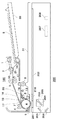
図1は、本発明の実施の形態に係る画像読取装置の構成を概略的に示す図である。 FIG. 1 is a diagram schematically showing a configuration of an image reading apparatus according to an embodiment of the present invention.
図1において、画像読取装置は、自動原稿送り装置100と画像読取装置本体200とから構成される。以下、その構成を動作と併せて説明する。
In FIG. 1, the image reading apparatus includes an
自動原稿送り装置100は、図1に示すように、少なくとも1枚以上のシートで構成される原稿束Sを載置する原稿トレイ30と、原稿の搬送開始前に、原稿トレイ30より突出し、原稿束Sの下流への進出を規制する分離パッド21と、給紙ローラ1とを有する。給紙ローラ1は、原稿トレイ30に載置された原稿束Sの原稿面に落下し、回転する。
As shown in FIG. 1, the
これにより、原稿束Sの最上面の原稿が給紙される。給紙ローラ1によって給送された原稿は分離ローラ2と分離パッド21の作用によって1枚に分離される。この分離は周知のリタード分離技術によって実現されている。
As a result, the uppermost document of the document bundle S is fed. The original fed by the
分離ローラ2と分離パッド21によって分離された原稿は、搬送ローラ対3により、レジストローラ4へ搬送され、レジストローラ4に突き当てられる。これにより、原稿はループ状に形成され、原稿の搬送における斜行が解消される。
The document separated by the
レジストローラ4の下流側には、レジストローラ4を通過した原稿を流し読みガラス201方向へ搬送する給紙パスが配置されている。
On the downstream side of the
給紙パスに送られた原稿は、大ローラ7及び給送ローラ5により流し読みガラス201上に送られる。ここで、大ローラ7は、原稿がなかった場合には流し読みガラス201に接触する。大ローラ7により給送された原稿は、搬送ローラ6を通過し、ローラ16と移動ガラス18の間を移動して、排紙フラッパ20及び排紙ローラ8を介して原稿排紙トレイ31へ排出される。このとき、原稿裏面読取部17にて原稿の裏面画像を読み取ることが可能である。排紙ローラ8の手前に排紙センサ13がある。
The document sent to the paper feed path is sent onto the
一方で、排紙ローラ8に原稿を噛ませた状態で、排紙ローラ8を逆転させて排紙フラッパ20を切り替えることにより、反転パス19へ原稿を移動させる。移動した原稿を反転パス19からレジストローラ4へ突き当て、再度原稿がループ状に形成されることによって、原稿の搬送における斜行を解消する。その後、給送ローラ5及び大ローラ7により再び原稿を流し読みガラス201へ移動させることで、原稿の裏面を流し読みガラス201で読み取ることが可能である。
On the other hand, the document is moved to the
また、原稿トレイ30には、それに載置された原稿束の副走査方向にスライド可能なガイド規制板(図示せず)が設けられているとともに、このガイド規制板に連動して原稿幅を検出する原稿幅検知センサ(図示せず)が設けられている。
Further, the
上記原稿幅検知センサとレジ前センサ11との組み合わせにより、原稿トレイ30上に載置された原稿束の原稿サイズが判別可能となる。また、搬送パス内に設けられた原稿長検知センサ(図示せず)により、搬送中の原稿の先端検知から後端検知までの搬送距離から原稿長を検出することも可能であり、検知した原稿長と上記原稿幅検知センサとの組み合わせからも、原稿サイズが判別可能である。
By combining the document width detection sensor and the
画像読取装置本体200は、原稿に記録された画像情報を光学的に読み取り、光電変換して画像データとして入力するものである。画像読取装置本体200は、流し読みガラス201、プラテンガラス202、ランプ203とミラー204を有するスキャナユニット209、ミラー205、206、レンズ207、CCD208等を有している。また、白板210は、シェーディングによる白レベルの基準データを作成するためのものである。
The image reading apparatus
図2は、図1の画像読取装置の機能ブロックを概略的に示す図である。 FIG. 2 is a diagram schematically showing functional blocks of the image reading apparatus of FIG.
自動原稿送り装置100は、CPU300、ROM301、RAM302その他を備えている。ROM301には、制御用プログラムが格納されており、RAM302には、入力データや作業用データが格納されている。また、出力ポートには、各種搬送用のローラを駆動するモータ303、ソレノイド306、クラッチ307が接続されており、入力ポートには、図示しない各種センサ304がそれぞれ接続されている。
The
CPU300は、これにバスを介して接続されたROM301に格納された制御プログラムに従って紙搬送を制御する。CPU300は、画像読取装置本体200のCPU321とライン351を介してシリアル通信を行い、画像読取装置本体200との間で制御データの授受を行うようになっている。また、原稿画像データの先端の基準となる画先信号も通信ラインを通して画像読取装置本体200に通知される。
The
また、図1の原稿裏面読取部17には、ランプ305及び近接型の受光センサ(CIS)308が接続されており、読み取った画像が画像処理部309へ転送される。
1 is connected to a
画像読取装置本体200は、CPU321、ROM322、RAM323、紙間補正を行う紙間補正部324、画像処理部325その他を備える。モータドライブ部326は、光学系駆動モータを駆動させるためのドライバ回路である。また、ランプ203、表面画像読取部(CCD)328が接続されている。
The image reading apparatus
CPU321は、モータドライブ部326及び表面画像読取部328などを用いて、画像読取装置本体200の制御を行う。レンズ207でCCD208上に結像された画像信号はデジタル画像データに変換され、画像処理部325で各種の画像処理を行い、画像メモリ329に書き込まれる。
The
また、自動原稿送り装置100内の画像処理部309で処理した画像も、画像通信ライン354を通して、画像メモリ329に保持される。画像メモリ329に書き込まれたデータは順次コントローラIF部353を通してコントローラ部400へ送信される。
An image processed by the
更に、原稿画像データの先端の基準となる画先信号については、CPU321でタイミングを取って、コントローラIF部352を通してコントローラ部400へ通知される。自動原稿送り装置100からの通信ラインで通知される画先信号についても同様に、画像読取装置本体200のCPU321でタイミングを取って、コントローラIF部352を通してコントローラ部400へ通知される。
Further, the image destination signal serving as the reference of the leading edge of the document image data is notified to the
コントローラ部400は、制御回路401、増幅回路402、A/D変換器403、補正回路404、画像メモリ405を有している。
The
CCD208からは、原稿画像を走査する過程で、読み取りの1ラインごとにアナログの画像信号が出力され、それらは増幅回路402により増幅された後、A/D変換器403により8ビットのデジタル信号に変換される。
In the process of scanning a document image, an analog image signal is output from the
そして、補正回路404は、画像信号に対して、紙間補正部324で作成された紙間補正データに基づいた補正処理を行う。その後、画像メモリ405に書き込まれていくことになる。以上の処理を原稿画像領域分行い、原稿の読み取り画像を形成する。
Then, the
尚、本実施の形態では、自動原稿送り装置100の原稿裏面読取部17にCIS、画像読取装置本体200の表面画像読取部にCCDを使用しているが、画像読み取りのセンサであれば何を使ってもよい。
In the present embodiment, the CIS is used for the document back
次に、片面に印刷がなされた原稿(片面原稿)を読み取る際、スキャナユニット209を副走査方向に移動させて画像を読み取る原稿読取モード(原稿固定読みモード)の動作について説明する。
Next, the operation of a document reading mode (document fixed reading mode) in which an image is read by moving the
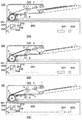
図3(a)乃至(d)は、図1の画像読取装置による原稿固定読み時におけるスキャナユニットの状態を模式的に示す図である。 FIGS. 3A to 3D are diagrams schematically illustrating a state of the scanner unit at the time of fixed document reading by the image reading apparatus of FIG.
画像読取装置本体200に画像読取開始の指示がされると、スキャナユニット209は、白板210の直下に移動し、主走査方向の白レベル基準及び、主走査方向の配光補正を行う(a)。スキャナユニット209は、自身を加速させるのに十分な距離が保持された(b)の位置へ移動する。
When the image reading
その後、スキャナユニット209は、図の矢印Aの方向(副走査方向)に移動し、原稿をランプ203にて照射しながら、反射光をCCD208にて読み取る(c)。原稿の右端部まで読み取りが終了した後、ランプ203を消灯し、図の矢印Bの方向へスキャナユニット209を移動し(d)、(a)の状態に戻る。
Thereafter, the
次に、原稿(片面及び両面原稿の表面)を読み取る際、スキャナユニット209を固定させて原稿を移動させることにより画像を読み取る原稿読取モード(原稿流し読みモード)の動作について説明する。
Next, the operation of a document reading mode (document flow reading mode) in which an image is read by fixing the
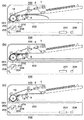
図4a〜図4cの(a)乃至(g)は、図1の画像読取装置による原稿流し読み時におけるスキャナユニットの状態を模式的に示す図である。 FIGS. 4A to 4C are diagrams schematically illustrating a state of the scanner unit during document scanning by the image reading apparatus of FIG.
自動原稿送り装置100に原稿の給送開始が指示されると、スキャナユニット209は白板210の直下に移動し、シェーディングを行う。ここで、原稿裏面読取部17の図示しない移動ガラス上の白基準板を用いて、同時にシェーディングを行う(a)。
When the
更に、給紙ローラ1が原稿上面に落下し、分離ローラ2、搬送ローラ対3の作用により、原稿束Sからその最上面にある1枚の原稿だけが分離され、レジストローラ4まで給送される。このときスキャナユニット209は、R点の直下へ移動する(b)。
Further, the
レジストローラ4が回転すると、原稿は給紙パスを経由して流し読みガラス201上へと導かれる(c)。原稿は、図中のR上を所定の速度で搬送され、原稿の画像はR点の下部に待機しているスキャナユニット209によって読み取られる。この際、原稿の先端がR点を通過するタイミングで、読み取り開始の信号を画像読取装置本体200に通知する。
When the
両面同時読みモードの場合、スキャナユニット209による原稿表面の読み取りと並行して、原稿裏面読取部17にて原稿の裏面画像の読み取りを行う(d)、(e)。
In the case of the double-sided simultaneous reading mode, the back side image of the original is read by the original back
原稿裏面読取部17が裏面の画像後端まで読み終わると(f)、読み取られた原稿はそのまま図の右方向へ搬送され、排紙ローラ8から自動原稿送り装置100の機外へ排出される。
When the document back
また、R点上をN枚目の原稿が読み取られている間に、原稿後端が搬送ローラ対3を通過すると、原稿トレイ30上に載置されている原稿束Sから(N+1)枚目の原稿の給送が開始される。この原稿は、同様に、流し読みガラス201へ搬送され、この原稿上の画像の読取動作が行われる。
If the trailing edge of the document passes the pair of
このとき、原稿がレジストローラ4に突き当てられた状態で、レジストローラ4の起動タイミングを操作することにより、R点上で読み取り中の前原稿との間隔が適時調整され、流し読みガラス201上では、所定の間隔で原稿が搬送される。
At this time, by operating the start timing of the
原稿の読み込み及び排紙が全て完了すると、図4cの(g)に示すように、スキャナユニット209を矢印の方向に移動させる。
When the reading and sheet ejection of the document is completed, as shown in (g) in FIG. 4 c, moves the
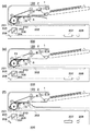
次に、原稿反転流し読みモードにおいて、原稿の表裏を反転させる動作について説明する。 Next, an operation for reversing the front and back of a document in the document reversal flow reading mode will be described.
図5a〜図5bの(a)乃至(f)は、図1の画像読取装置による原稿反転時におけるスキャナユニットの状態を模式的に示す図である。 FIGS. 5A to 5B are diagrams schematically illustrating a state of the scanner unit when the document is reversed by the image reading apparatus of FIG.
図4a〜図4cの(a)乃至(g)の一連の動作により(ただし、N枚目の原稿を読んでいる最中には、(N+1)枚目の原稿の給送を行わず、かつ、原稿裏面読取部17を使用しないものとする)、原稿を排紙部に噛ませた状態で停止させる。(a)。
4a to 4c (a) to (g) in a series of operations (however, while the Nth original is being read, the (N + 1) th original is not fed, In addition, the document back
排紙ローラ8を排紙と逆の方向に回転させることにより、(b)の矢印の方向へ原稿を移動させる。このとき、原稿後端が排紙センサ13で検知されたら、排紙ローラ8を停止させる。
By rotating the
原稿裏面をR点上にて読み取りながら搬送し(c)、その後、排紙ローラ8に再度原稿を噛ませた状態で停止させる(d)。更に、排紙ローラ8を逆転させて(e)の矢印の方向に原稿を移動させ、原稿の表裏を反転させる。原稿反転後、原稿トレイ30上の次の原稿の分離を開始する(f)。
The back side of the document is conveyed while reading on the R point (c), and then stopped while the document is again bitten by the paper discharge roller 8 (d). Further, the
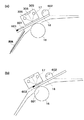
図6は、図1における原稿裏面読取部近傍の拡大図である。 FIG. 6 is an enlarged view of the vicinity of the document back side reading unit in FIG.
図6において、原稿裏面読取部17を含めた周辺の構成は、大きく、原稿裏面読取部17、ローラ16、移動ガラス18からなる。原稿裏面読取部17はさらに、通過する原稿面を照らすためのランプ305と受光センサ(CIS)308とから構成される。
In FIG. 6, the peripheral configuration including the document back
移動ガラス18の周辺には、移動ガラス18を移動させるためのガラス駆動部602と、前述したように原稿裏面読取部17においてもシェーディングを行うための白板601と、移動ガラス18の基準位置出しのための黒ベタ部材603が設けられている。
Around the moving
ここで、ローラ16の表面は白色である。これはローラ表面を読み取ることにより、ランプ305とCIS308との間の配光特性を補正するためである。シェーディング調整時には配光補正を、白板601を用いても行うが、原稿が連続して搬送されている状態ではその都度白板601を画像読み位置に移動させて配光補正を行うだけの時間がない。そのため、紙間を利用してローラ16の表面を読んで配光補正を行う。
Here, the surface of the
従って、CIS308で読み取った画像データは、ローラ16表面であっても白板601であっても同じ白データとなり区別がつかなくなることから、黒ベタ部材603を設けて位置出しの基準とする。
Accordingly, since the image data read by the
図6(a)は、図上の下方向から原稿が搬送されてきて、これから原稿裏面読取部17において原稿の裏面画像が読み取られる状態を示している。
FIG. 6A shows a state in which the original is conveyed from the lower side in the figure and the back side image of the original is read by the back
図6(b)は、原稿裏面読取部17におけるシェーディング調整の状態を示している。ガラス駆動部602によって白板601が画像読み取り位置に移動され、原稿裏面読取部17によって基準となる白色の読み取りがなされている。
FIG. 6B shows a state of shading adjustment in the document back
図7は、図6における原稿裏面読取部の初期化処理の手順を示すフローチャートである。 FIG. 7 is a flowchart showing a procedure of initialization processing of the document back side reading unit in FIG.
図7において、まず、ステップS801で初期化処理の開始を待つ。初期化処理の開始を受けたらランプ305を消灯する(ステップS802)。そしてランプ305を消灯した状態で黒レベル調整を行う(ステップS803)。
7, firstly, waits for the start of the initialization process in
黒レベル調整では、CIS308が黒色を読み取った時の黒データ出力を調整する。黒レベル調整の終了を受けてランプ305を点灯する(ステップS804)。ランプ305が点灯したら、一度CIS308で画像読み取りを行い(ステップS805)、黒ベタ部材603(黒帯)が検知できるか否かを判定する(ステップS806)。
In the black level adjustment, the black data output when the
黒ベタ部材603が検出できていた場合には、移動ガラス18を一旦逆方向に(後述する図8で示す方向B)に所定距離だけ移動させる(ステップS807)。この所定距離とは、初期状態において読み取り位置が黒ベタ部材603内のどの位置にあっても確実に黒帯領域を抜けるだけの移動量である。
If the black
ステップS806において黒帯検知できなかった場合、あるいはステップS807においてバック移動した後は、移動ガラス18を順方向(後述する図8で示す方向A)に移動させ(ステップS808)、CIS308で画像を読み取る(ステップS809)。そして、黒ベタ部材603(黒帯)が検知できるか否かを判定し(ステップS810)、黒帯検知するまで上記ステップS808からステップS810の処理を繰り返す。
When the black band cannot be detected in
その後、ステップS810において、黒ベタ部材603が検知できた時点で移動ガラス18の駆動を停止し(ステップS811)、その位置を移動ガラスの基準位置(ホームポジション=HP)と設定する(ステップS812)。
Thereafter, in
前述したように、スキャナユニット209を移動して画像読み取りする場合には、原稿位置と画像読み取り位置とを高精度で合わせるために、スキャナユニット209のHP検知も高精度で行う必要がある。
As described above, when scanning the image by moving the
しかし、本発明のように裏面読み取り位置が固定の場合には、原稿位置と画像読み取り位置は一意に定まるため、移動ガラス18のHP出しは表面読取部ほどの精度を必要としない。
However, when the back surface reading position is fixed as in the present invention, the document position and the image reading position are uniquely determined, and therefore the HP of the moving
HPが決まった後は、ステップS813において、移動ガラス18を白板601に対向する所定の白板読み位置まで移動させ、シェーディング調整を行う(ステップS814)。その後、ランプ305を消灯し(ステップS815)、移動ガラス18を所定の画像読み位置まで移動させて(ステップS816)、原稿裏面読取部17の初期化処理を終了する。
After HP has been determined, in
図8は、図6における白板と黒ベタ部材の関係の第1の例を示す図である。 FIG. 8 is a diagram showing a first example of the relationship between the white plate and the black solid member in FIG.
図8において、帯状の黒ベタ部材603は白板601の外側端部に設けてある。
In FIG. 8, a belt-like black
図9は、図6における白板と黒ベタ部材の関係の第2の例を示す図である。 FIG. 9 is a diagram showing a second example of the relationship between the white plate and the black solid member in FIG.
図9において、帯状の黒ベタ部材603は白板601の内側端部に設けてある。ただしこの場合には、初期化処理開始時に画像読み取り位置が白板601側になっていないようにする必要がある。白板601側にあった場合には、移動ガラス18を順方向に移動させても黒ベタ部材603は検知されないためである。
In FIG. 9, a strip-shaped black
図10は、図6における白板と黒ベタ部材の関係の第3の例を示す図である。 FIG. 10 is a diagram illustrating a third example of the relationship between the white plate and the black solid member in FIG.
図10において、黒ベタ部材603は、白板601の外側端部2箇所にマークとして設けてある。この場合、マークはゴミと誤判断しないようなマークとする必要がある。読み込んだ画像データ全体を見てHP判断するのではなく、マークがある領域だけをチェックすることにより、処理の軽減を図ることができる。
In FIG. 10, the black
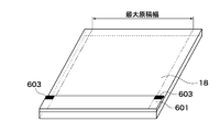
図11は、図6における白板と黒ベタ部材の関係の第4の例を示す図である。 FIG. 11 is a diagram illustrating a fourth example of the relationship between the white plate and the black solid member in FIG. 6.
前記第1乃至第3の例においては、黒ベタ部材603は白板601上に設けられ、加えて原稿領域内に設けられていた。原稿領域とは、CIS308の主走査範囲内において原稿が通過する可能性のある領域(最大原稿幅)のことを指している。これは、黒ベタ部材603がある部分は白板として使用できないことを意味する。一方で、最大原稿幅とCIS308の主走査範囲とを比較した場合には、最大原稿幅より外側の原稿領域外も走査可能である場合が多い。
In the first to third examples, the black
図11においては、黒ベタ部材603は、白板601の内側端部2箇所の原稿領域外にマークとして設けてある。HP検知時にはマークとして、それ以外では白板として使用可能な形態としたものである。
In FIG. 11, the black
図12は、図6における白板と黒ベタ部材の関係の第5の例を示す図である。 FIG. 12 is a diagram illustrating a fifth example of the relationship between the white plate and the black solid member in FIG. 6.
前記第1乃至第4の例においては、黒ベタ部604は白板601上に設けられていた。しかし、前記第4の例と同様に、原稿領域外にマークすることを考えると必ずしも白板601上である必要はない。
In the first to fourth examples, the black solid portion 604 is provided on the
図12においては、移動ガラス18上の原稿領域外にマーク状の黒ベタ部材603を付けることにより、HP検知時にはマークとして、通常時にはガラスとして使用可能な形態としたものである。
In FIG. 12, a mark-shaped black
17 原稿裏面読取部(第2の画像読取手段)
18 移動ガラス(仕切り部材)
100 自動原稿送り装置
200画像読取装置本体
208 CCD(第1の画像読取手段構成要素)
209 スキャナユニット(第1の画像読取手段構成要素)
601 白板
603 黒ベタ部材(基準部材)
300 CPU(制御手段)
321 CPU(制御手段)
17 Document back side reading unit (second image reading unit)
18 Moving glass (partition member)
DESCRIPTION OF
209 Scanner unit (first image reading means component)
601
300 CPU (control means)
321 CPU (control means)
Claims (6)
原稿を搬送する搬送手段と、
原稿の第一面を読み取る、移動可能な第1原稿読取手段と、
前記第1原稿読取手段が移動可能な範囲内に配置された第1白色部材と、
前記第1原稿読取手段を移動させる第1移動手段と、
前記原稿の第二面を読み取る、移動不可能な第2原稿読取手段と、
第2白色部材と、基準部材と、透明部分を有する移動可能な移動部材と、
前記移動部材を移動させる第2移動手段と、
前記第1移動手段に前記第1原稿読取手段を前記第1白色部材の下に移動させ前記第1原稿読取手段のシェーディング調整を行い、前記第2移動手段に前記移動部材を移動させた際の前記第2原稿読取手段の出力値に基づき前記基準部材を検知し、該基準部材の検知に基づき前記第2移動手段に前記第2原稿読取手段が前記第2白色部材が読み取れるように前記移動部材の前記透明部分を移動させ前記第2原稿読取手段のシェーディング調整を行う制御手段とを有し、
前記第1移動手段が前記第1原稿読取手段を移動させて前記原稿台の上に載置された原稿の前記第一面を読み取る原稿固定読みモードと、
所定位置に移動させられた前記1原稿読取手段により、前記搬送手段により搬送される原稿の前記第一面を読み取り、前記第2原稿読取手段により該移動する原稿の前記第二面を前記移動部材の前記透明部分を介して読み取る原稿流し読みモードと、
を有することを特徴とする原稿読取装置。 A document table on which the document is placed;
Conveying means for conveying an original;
A movable first document reading means for reading the first side of the document;
A first white member disposed within a movable range of the first document reading unit;
First moving means for moving the first document reading means;
Non-movable second document reading means for reading the second surface of the document;
A movable member having a second white member, a reference member, and a transparent portion;
Second moving means for moving the moving member;
When the first moving unit moves the first document reading unit below the first white member to adjust shading of the first document reading unit, and moves the moving member to the second moving unit. The reference member is detected based on an output value of the second document reading means, and the moving member is readable by the second moving means so that the second document reading means can read the second white member based on the detection of the reference member. Control means for moving the transparent portion of the second document reading means and adjusting shading of the second document reading means,
A fixed document reading mode in which the first moving unit moves the first document reading unit to read the first surface of the document placed on the document table;
The first original reading means moved to a predetermined position reads the first surface of the original conveyed by the conveying means, and the second original reading means moves the second surface of the moving original to the moving member. Document scanning mode for reading through the transparent portion of
Document reading apparatus characterized by having a.
Priority Applications (1)
| Application Number | Priority Date | Filing Date | Title |
|---|---|---|---|
| JP2006248334A JP4854436B2 (en) | 2006-09-13 | 2006-09-13 | Document reader |
Applications Claiming Priority (1)
| Application Number | Priority Date | Filing Date | Title |
|---|---|---|---|
| JP2006248334A JP4854436B2 (en) | 2006-09-13 | 2006-09-13 | Document reader |
Publications (3)
| Publication Number | Publication Date |
|---|---|
| JP2008072356A JP2008072356A (en) | 2008-03-27 |
| JP2008072356A5 JP2008072356A5 (en) | 2009-11-12 |
| JP4854436B2 true JP4854436B2 (en) | 2012-01-18 |
Family
ID=39293566
Family Applications (1)
| Application Number | Title | Priority Date | Filing Date |
|---|---|---|---|
| JP2006248334A Expired - Fee Related JP4854436B2 (en) | 2006-09-13 | 2006-09-13 | Document reader |
Country Status (1)
| Country | Link |
|---|---|
| JP (1) | JP4854436B2 (en) |
Families Citing this family (1)
| Publication number | Priority date | Publication date | Assignee | Title |
|---|---|---|---|---|
| JP6152649B2 (en) * | 2013-01-31 | 2017-06-28 | 株式会社リコー | Image reading apparatus, automatic document feeder, and image forming apparatus |
Family Cites Families (3)
| Publication number | Priority date | Publication date | Assignee | Title |
|---|---|---|---|---|
| JPH01141461A (en) * | 1987-11-28 | 1989-06-02 | Toshiba Corp | Reader |
| JP3078849B2 (en) * | 1990-12-26 | 2000-08-21 | キヤノン株式会社 | Image reading device |
| JPH0530302A (en) * | 1991-07-18 | 1993-02-05 | Canon Inc | Picture reader |
-
2006
- 2006-09-13 JP JP2006248334A patent/JP4854436B2/en not_active Expired - Fee Related
Also Published As
| Publication number | Publication date |
|---|---|
| JP2008072356A (en) | 2008-03-27 |
Similar Documents
| Publication | Publication Date | Title |
|---|---|---|
| JP4677420B2 (en) | Image reading device | |
| JP5192167B2 (en) | Image reading device | |
| US8488209B2 (en) | Image reader, and control method and control program for the same | |
| US20060103898A1 (en) | Image reading apparatus, image forming apparatus, control method, and program | |
| JP4926791B2 (en) | Image reading device | |
| JP4854436B2 (en) | Document reader | |
| JP2003315934A (en) | Image reader | |
| JP2007195009A (en) | Image reading apparatus | |
| JP4056011B2 (en) | Document reader | |
| JP2007166207A (en) | Original reader | |
| US11750753B2 (en) | Image reading device, image forming apparatus, and image reading method | |
| JP2006261847A (en) | Original reading device | |
| JP2008263355A (en) | Image reader | |
| JP4528319B2 (en) | Document reader | |
| JP2018125766A (en) | Image reading apparatus | |
| JP3693833B2 (en) | Image reading device | |
| JP2005184101A (en) | Image reader | |
| JP2007158849A (en) | Image reader | |
| JP2005065128A (en) | Image reader | |
| JP3654530B2 (en) | Double-sided document reader and image forming apparatus | |
| JP2022181880A (en) | Image reading device, method for controlling image reading device, and program | |
| JP5025332B2 (en) | Image reading device | |
| JP2005005752A (en) | Original reader | |
| JP4516382B2 (en) | Image reading device | |
| JP4905236B2 (en) | Image reading apparatus and image forming apparatus |
Legal Events
| Date | Code | Title | Description |
|---|---|---|---|
| A521 | Written amendment |
Free format text: JAPANESE INTERMEDIATE CODE: A523 Effective date: 20090911 |
|
| A621 | Written request for application examination |
Free format text: JAPANESE INTERMEDIATE CODE: A621 Effective date: 20090911 |
|
| A521 | Written amendment |
Free format text: JAPANESE INTERMEDIATE CODE: A523 Effective date: 20090916 |
|
| A977 | Report on retrieval |
Free format text: JAPANESE INTERMEDIATE CODE: A971007 Effective date: 20110308 |
|
| A131 | Notification of reasons for refusal |
Free format text: JAPANESE INTERMEDIATE CODE: A131 Effective date: 20110315 |
|
| A521 | Written amendment |
Free format text: JAPANESE INTERMEDIATE CODE: A523 Effective date: 20110502 |
|
| TRDD | Decision of grant or rejection written | ||
| A01 | Written decision to grant a patent or to grant a registration (utility model) |
Free format text: JAPANESE INTERMEDIATE CODE: A01 Effective date: 20111020 |
|
| A01 | Written decision to grant a patent or to grant a registration (utility model) |
Free format text: JAPANESE INTERMEDIATE CODE: A01 |
|
| A61 | First payment of annual fees (during grant procedure) |
Free format text: JAPANESE INTERMEDIATE CODE: A61 Effective date: 20111025 |
|
| FPAY | Renewal fee payment (event date is renewal date of database) |
Free format text: PAYMENT UNTIL: 20141104 Year of fee payment: 3 |
|
| FPAY | Renewal fee payment (event date is renewal date of database) |
Free format text: PAYMENT UNTIL: 20141104 Year of fee payment: 3 |
|
| LAPS | Cancellation because of no payment of annual fees |