JP4853471B2 - Control device for an internal combustion engine with a supercharger - Google Patents
Control device for an internal combustion engine with a supercharger Download PDFInfo
- Publication number
- JP4853471B2 JP4853471B2 JP2007327430A JP2007327430A JP4853471B2 JP 4853471 B2 JP4853471 B2 JP 4853471B2 JP 2007327430 A JP2007327430 A JP 2007327430A JP 2007327430 A JP2007327430 A JP 2007327430A JP 4853471 B2 JP4853471 B2 JP 4853471B2
- Authority
- JP
- Japan
- Prior art keywords
- turbine
- blade opening
- pressure
- turbine blade
- calculated
- Prior art date
- Legal status (The legal status is an assumption and is not a legal conclusion. Google has not performed a legal analysis and makes no representation as to the accuracy of the status listed.)
- Expired - Fee Related
Links
Images


Classifications
-
- Y—GENERAL TAGGING OF NEW TECHNOLOGICAL DEVELOPMENTS; GENERAL TAGGING OF CROSS-SECTIONAL TECHNOLOGIES SPANNING OVER SEVERAL SECTIONS OF THE IPC; TECHNICAL SUBJECTS COVERED BY FORMER USPC CROSS-REFERENCE ART COLLECTIONS [XRACs] AND DIGESTS
- Y02—TECHNOLOGIES OR APPLICATIONS FOR MITIGATION OR ADAPTATION AGAINST CLIMATE CHANGE
- Y02T—CLIMATE CHANGE MITIGATION TECHNOLOGIES RELATED TO TRANSPORTATION
- Y02T10/00—Road transport of goods or passengers
- Y02T10/10—Internal combustion engine [ICE] based vehicles
- Y02T10/12—Improving ICE efficiencies
Description
本発明は、可変翼調整機構を有する過給機を備えた内燃機関の制御装置に関する。 The present invention relates to a control device for an internal combustion engine including a supercharger having a variable blade adjustment mechanism.
排気動力を用いて吸入空気を過給する過給機としてターボチャージャが知られている。一般的に、ターボチャージャは、吸気管に設けられたコンプレッサと排気管に設けられたタービンとを有し、それらがシャフトにて連結されており、排気管を流れる排気ガスによってタービンが回転し、その回転力がシャフトを介してコンプレッサに伝達されることによって、吸気管内を流れる吸入空気量が圧縮されて過給が行われる。また、近年では、ターボチャージャのタービン側に可変翼開度調整機構を取り付け、この可変翼開度調整機構により、タービンを制御することによって、所望の過給圧(目標過給圧)を得る過給機付き内燃機関の制御装置が開発されている(特許文献1参照)。なお、可変翼開度調整機構は、タービン翼の開度(以下、「タービン翼開度」という)を調整することによって、タービンに流入する排気ガスの流入角度を調整することができ、タービン動力、つまりはコンプレッサ動力を制御することができる。つまり、可変翼開度調整機構は、タービン翼開度を調整しタービンを制御することで、コンプレッサによって圧縮される吸入空気量の過給圧を制御することができる。このように、可変翼開度調整機構を備えた過給機において、例えば、特許文献1には、目標過給圧を得るために、ターボチャージャのモデルを用いてタービン翼開度を求めることが開示されている。より具体的には、まず、ターボチャージャのコンプレッサが圧縮すべき空気の目標過給圧よりコンプレッサ側の熱力学モデルから目標コンプレッサ動力を求め、この目標コンプレッサ動力にコンプレッサとタービンと連結するシャフトなどの摩擦損失等を考慮することで目標タービン動力を求め、次に、目標タービン動力よりタービン側の熱力学モデルを用いてタービン入口圧とタービン出口圧との膨張比を算出し、所定のタービン翼開度に対するタービン入口圧とタービン出口圧との膨張比と排気ガス流量との関係(以下、「タービン特性」という)を用いてタービン翼開度を求め、目標過給圧を得るようにする技術が開示されている。
ここで、タービン特性は、基準となるターボチャージャで測定されたタービン特性が予め設定されている。しかしながら、実際の個々のターボチャージャのタービン特性は、可変翼調整機構の設置位置のばらつき等の影響により、基準となるターボチャージャで測定されたタービン特性とは異なる。このため、基準となるターボチャージャで測定されたタービン特性を個々のターボチャージャに適用すると、所望の過給圧を得ることができない虞がある。また、特に、特許文献1のようにモデルを用いる場合には、タービン特性の誤差が制御性に大きく影響することが考えられる。
Here, the turbine characteristics measured by the reference turbocharger are set in advance as the turbine characteristics. However, the actual turbine characteristics of each turbocharger differ from the turbine characteristics measured by the reference turbocharger due to the influence of variations in the installation position of the variable blade adjustment mechanism. For this reason, when the turbine characteristics measured by the reference turbocharger are applied to individual turbochargers, there is a possibility that a desired supercharging pressure cannot be obtained. In particular, when a model is used as in
そこで、本願発明は、可変翼調整機構の設置位置のばらつき等を考慮することで所望の過給圧を得ることが可能な過給機付き内燃機関の制御装置を提供することを目的とする。 Accordingly, an object of the present invention is to provide a control device for an internal combustion engine with a supercharger capable of obtaining a desired supercharging pressure by taking into account variations in the installation position of the variable blade adjustment mechanism.
そこで、請求項1に係る発明では、内燃機関の排気通路に設けられたタービンを排気圧力で駆動することで吸気通路に設けられたコンプレッサを駆動して筒内に空気を過給する過給機と、タービンの翼開度(以下、「タービン翼開度」という)を調整する可変翼開度調整機構と、タービンの入口圧(以下、「タービン入口圧」という)又は該タービン入口圧と相関のあるパラメータからタービン翼開度を算出するマップ(以下、「タービン特性」という)を備え、内燃機関の運転状態に基づいてコンプレッサで過給する目標過給圧を算出し、該目標過給圧に基づいてタービン入口圧又は該タービン入口圧と相関のあるパラメータを求め、タービン特性を用いて可変翼調整機構により調整されるタービン翼開度を算出する過給機のモデルを備えた過給機付き内燃機関の制御装置において、過給機のモデルを用いて、内燃機関の運転状態に基づく目標過給圧となるようにタービンの翼開度(以下、「第1のタービン翼開度」という)を算出する第1のタービン翼開度算出手段と、実際にタービン入口圧(以下、「第2のタービン入口圧」という)を検出し、第2のタービン入口圧又は該第2のタービン入口圧と相関のあるパラメータからタービン特性を用いて、タービンの翼開度(以下、「第2のタービン翼開度」という)を算出する第2のタービン翼開度算出手段とを備え、第2のタービン翼開度算出手段により算出された第2のタービン翼開度と第1のタービン翼開度算出手段により算出された第1のタービン翼開度とに基づいて、タービン特性を補正する学習補正手段を備える。
Therefore, in the invention according to
これにより、可変翼調整機構の設置位置のばらつき等の影響により、基準となるターボチャージャで測定されたタービン特性と実際のタービン特性とが異なる場合においても、実際のタービン入口圧に基づいて算出されたタービン翼開度(第2のタービン翼開度)と目標過給圧となるように設定された第1のタービン翼開度(第1のタービン翼開度)とに基づいて、過給機のタービン翼開度を算出する際に用いるタービン特性を補正することで、目標過給圧を得るための適切なタービン翼開度を算出することが可能となる。つまり、従来よりも所望の過給圧を得る応答性を速くすることが可能となる。 As a result, even if the turbine characteristics measured by the reference turbocharger differ from the actual turbine characteristics due to the effect of variations in the installation position of the variable blade adjustment mechanism, the calculation is based on the actual turbine inlet pressure. Based on the turbine blade opening (second turbine blade opening) and the first turbine blade opening (first turbine blade opening) set to be the target supercharging pressure By correcting the turbine characteristics used when calculating the turbine blade opening, it is possible to calculate an appropriate turbine blade opening for obtaining the target supercharging pressure. That is, it is possible to speed up the responsiveness to obtain a desired supercharging pressure as compared with the prior art.
ここで、第1のタービン翼開度に対して実際のタービン翼開度が遅れて制御されるため、請求項2に係る発明のように、第1のタービン翼開度算出手段は、該第1のタービン翼開度算出手段により算出された第1のタービン翼開度をむだ時間と1次遅れで補正する補正手段を備え、学習補正手段は、第2のタービン翼開度算出手段により算出された第2のタービン翼開度と補正手段により補正された第1のタービン翼開度とに基づいて、タービン特性を補正すると良い。 Here, since the actual turbine blade opening is controlled with a delay with respect to the first turbine blade opening, the first turbine blade opening calculation means, as in the invention according to claim 2, Correction means for correcting the first turbine blade opening degree calculated by one turbine blade opening degree calculation means with a dead time and a first-order lag, and the learning correction means is calculated by the second turbine blade opening degree calculation means. The turbine characteristics may be corrected based on the second turbine blade opening and the first turbine blade opening corrected by the correcting means.
このように、補正された第1のタービン翼開度と実際のタービン翼開度(第2のタービン翼開度)を比較することで、精度良くタービン特性を学習することが可能となる。 Thus, by comparing the corrected first turbine blade opening and the actual turbine blade opening (second turbine blade opening), it is possible to learn the turbine characteristics with high accuracy.
また、請求項3に係る発明のように、学習補正手段は、タービン特性において、第2のタービン入口圧又は該第2のタービン入口圧と相関のあるパラメータに基づいて算出されたタービン翼開度を第2のタービン翼開度と第1のタービン翼開度との偏差に基づいて補正すると良い。例えば、図11のようなマップが予めECU内に備えられている場合には、第2のタービン入口圧又は該第2のタービン入口圧と相関のあるパラメータに基づいて算出された該当するタービン翼開度を、第2のタービン翼開度と第1のタービン翼開度との偏差に基づいて補正すると良い。
Further, as in the invention according to
また、タービン入口圧と相関のあるパラメータとは、タービン入口圧とタービンの出口圧(以下、「タービン出口圧」という)との膨張比、またはタービンの動力(以下、「タービン動力」という)とすると良い(請求項4)。ここで、タービン動力は、タービン入口圧に基づいて算出することが可能である。 The parameter correlated with the turbine inlet pressure is the expansion ratio between the turbine inlet pressure and the turbine outlet pressure (hereinafter referred to as “turbine outlet pressure”), or the turbine power (hereinafter referred to as “turbine power”). Then, it is good (Claim 4). Here, the turbine power can be calculated based on the turbine inlet pressure.
[実施形態(1)]
以下、図を用いて内燃機関であるディーゼルエンジンに適用した本実施形態を説明する。まず、図1は、エンジン制御システムの全体概要構成図であり、図2は図1を簡素化した概要構成図である。
[Embodiment (1)]
Hereinafter, this embodiment applied to the diesel engine which is an internal combustion engine is described using figures. First, FIG. 1 is an overall schematic configuration diagram of an engine control system, and FIG. 2 is a schematic configuration diagram obtained by simplifying FIG.
図1に示すエンジン10において、シリンダブロック11にはピストン12が収容され、シリンダ内壁とピストン12とシリンダヘッド13とにより燃焼室14が区画形成されている。シリンダヘッド13には電気制御式の燃料噴射弁15が配設されている。この燃料噴射弁15にはコモンレール16から高圧燃料が給送され、燃料噴射弁15の開動作に伴い燃焼室14内に燃料が噴射供給される。なお図示は省略するが、本システムでは、燃料タンク内の燃料をコモンレール16に圧送するための燃料ポンプを備えており、センサ等で検出したコモンレール内圧力(燃料圧)に基づいて燃料ポンプの燃料吐出量が制御されるようになっている。
In the
吸気ポートには吸気弁17が配設され、排気ポートには排気弁18が配設されている。また、吸気ポートには吸気管21が接続されており、吸気管21においてサージタンク22よりも上流側にはインタークーラ37が設けられている。サージタンク22には、吸気管圧力(後述するターボチャージャの過給圧でもある)を検出する吸気圧センサ23が設けられている。排気ポートには排気管24が接続されている。
An intake valve 17 is disposed at the intake port, and an exhaust valve 18 is disposed at the exhaust port. An intake pipe 21 is connected to the intake port, and an intercooler 37 is provided upstream of the surge tank 22 in the intake pipe 21. The surge tank 22 is provided with an
吸気管21と排気管24との間にはターボチャージャ30が配設されている。ターボチャージャ30は、吸気管21に設けられたコンプレッサインペラ31と、排気管24に設けられたタービンホイール32とを有し、それらがシャフト33にて連結されている。また、タービンホイール32には、タービンホイール32の開度(以下、「タービン翼開度」という)を調整可能な可変翼調整機構53が設けられている。
A turbocharger 30 is disposed between the intake pipe 21 and the
ターボチャージャ30では、排気管24を流れる排気によってタービンホイール32が回転し、その回転力がシャフト33を介してコンプレッサインペラ31に伝達される。そして、コンプレッサインペラ31により、吸気管21内を流れる吸入空気が圧縮されて過給が行われる。なお、可変翼調整機構53で、タービン翼開度を調整することで、タービン入口圧とタービン出口圧との膨張比を可変に設定することができ、タービンホイール32の回転を調整することができる。つまりは、可変翼調整機構53により、タービン翼開度を調整することで、空気の過給圧を制御することが可能となる。ターボチャージャ30にて過給された空気は、インタークーラ37によって冷却された後、その下流側に給送される。インタークーラ37によって吸入空気が冷却されることで、吸入空気の充填効率が高められる。また、インタークーラ37には、スロットル弁26が設けられている。
In the turbocharger 30, the
吸気管21の最上流部には図示しないエアクリーナが設けられ、このエアクリーナの下流側には、吸入空気量を検出するエアフロメータ51と、吸入空気量の温度を検出する吸気温センサ52とが設けられている。その他、本制御システムでは、エンジン10の回転に伴い所定クランク角毎に(例えば30°CA周期で)矩形状のクランク角信号を出力するクランク角度センサ27、アクセルペダルの踏み込み操作量(アクセル開度)を検出するアクセル開度センサ28、大気圧を検出する大気圧センサ29等の各種センサが設けられている。
An air cleaner (not shown) is provided at the most upstream portion of the intake pipe 21, and an
また、図示は省略するが、排気管24においてターボチャージャ30のタービン下流側にはNOx吸収剤を内蔵した触媒装置が設けられている。更に、吸気管24においてターボチャージャ30のコンプレッサ下流側と排気管24において触媒装置の上流側との間にはEGR通路42が設けられており、そのEGR通路42の途中には、エンジン冷却水等によりEGRガスを冷却するEGRインタークーラと、EGR制御弁44とが配設されている。
Although not shown, a catalyst device containing a NOx absorbent is provided in the
エンジンECU(電子制御ユニット)50は、周知の通りCPU、ROM、RAM等よりなるマイクロコンピュータを主体として構成され、ROMに記憶された各種の制御プログラムを実行することで、その都度のエンジン運転状態に応じてエンジン10の各種制御を実施する。すなわち、エンジンECU50には、前述した各種センサから各々検出信号が入力される。そして、エンジンECU50は、随時入力される各種の検出信号に基づいて燃料噴射量、スロットル弁制御量、EGR制御量、燃圧制御量等を演算し、それらに基づいて燃料噴射弁、スロットル弁26、EGR制御弁44、燃料ポンプ等の駆動を制御する。
As is well known, the engine ECU (electronic control unit) 50 is mainly composed of a microcomputer composed of a CPU, ROM, RAM, etc., and executes various control programs stored in the ROM, so that the engine operating state in each case. Various controls of the
図3は、エンジンECU50の中に組み込まれた過給圧制御の制御ブロック図である。この制御ブロック図を使って過給圧制御の概要を説明する。エンジンECU50は、例えば、エンジン運転状態に基づいて目標過給圧P1E_trgを算出する。求められた目標過給圧および図3には記載のない他のエンジン運転状態、例えば吸入空気量や吸入空気温に基づき、フィードフォワード制御器B30にてタービン翼開度の基本位置VN_base(以下、「可変翼開度基本位置」という)を算出する。また、目標過給圧P1E_trgとエンジン上で計測された実過給圧P1Eとの差ΔP1Eに基づきフィードバック制御器B20にてフィードバック量P1E_fbを算出する。次に、可変翼開度基本位置VN_baseにフィードバック量P1E_fbを加えて過給圧を目標に制御するためのタービン翼開度VN_trg(以下、「指令可変翼開度位置」という)が算出される。なお、本願発明では、フィードバック制御器B20には、PID制御器を採用していており、フィードバック制御機B20にて算出されたフィードバック量P1E_fbは、タービン翼開度を制御する制御量である。
FIG. 3 is a control block diagram of the supercharging pressure control incorporated in the
図4は、図3のフィードフォワード制御器B30の中に組み込まれるフィードフォワードモデル制御ブロック図である。フィードフォワードモデルは、ターボチャージャに視点を置いて、エンジン全体をモデルで表現することで、目標過給圧を得るためのタービン翼開度の基本位置(可変翼開度基本位置)VN_baseを算出するものである。以下、図4を用いて、フィードフォワードモデルについて説明する。 FIG. 4 is a block diagram of a feedforward model control incorporated in the feedforward controller B30 of FIG. The feedforward model calculates the basic position of the turbine blade opening (variable blade opening basic position) VN_base for obtaining the target supercharging pressure by expressing the entire engine as a model with a viewpoint on the turbocharger. Is. Hereinafter, the feedforward model will be described with reference to FIG.
まず、目標過給圧P1E_trgを算出する。なお、目標過給圧P1E_trgは、エンジンの運転状態から算出しても良いし、運転者が要求する目標トルクに基づいて算出しても良い。目標トルクを基に目標過給圧P1E_trgを算出する場合、目標トルクから目標燃料噴射量を算出し、該目標燃料噴射量とエンジン回転速度とに基づいて算出すると良い。ここで、目標トルクは、例えば、運転者によって踏み込まれるアクセルのアクセル開度に基づいて算出される。 First, the target boost pressure P1E_trg is calculated. The target boost pressure P1E_trg may be calculated from the operating state of the engine or may be calculated based on the target torque requested by the driver. When calculating the target boost pressure P1E_trg based on the target torque, it is preferable to calculate the target fuel injection amount from the target torque and to calculate based on the target fuel injection amount and the engine speed. Here, the target torque is calculated based on, for example, the accelerator opening of the accelerator that is depressed by the driver.
目標過給圧P1E_trgが算出されると、制御ブロックB31にてエンジンに吸入される目標ガス量Geng_trgが算出される。目標ガス量Geng_trgは、吸気ガス密度とエンジンに吸入する体積効率とに基づいて算出される。まず、制御ブロックB31において、目標過給圧P1E_trgと同様に求められる目標吸気温Teng_trgに基づき吸気ガスの密度ρが算出される。なお、目標吸気温Teng_trgの算出方法は、例えば、所望の目標過給圧を得るための吸入空気温として、目標過給圧をパラメータとしたマップを用いて設定すると良い。また、吸気温センサによって検出された吸気温を目標吸気温として設定しても良い。なお、本実施形態のようにインタークーラが取り付けられている場合には、吸入空気がインタークーラを通過することにより冷却された吸気温を推定して、この吸気温を目標吸気温として設定すると良い。 When the target boost pressure P1E_trg is calculated, the target gas amount Geng_trg that is drawn into the engine is calculated in the control block B31. The target gas amount Geng_trg is calculated based on the intake gas density and the volumetric efficiency sucked into the engine. First, in the control block B31, the intake gas density ρ is calculated based on the target intake air temperature Teng_trg obtained in the same manner as the target boost pressure P1E_trg. Note that a method for calculating the target intake air temperature Teng_trg may be set using, for example, a map using the target boost pressure as a parameter as the intake air temperature for obtaining a desired target boost pressure. Further, the intake air temperature detected by the intake air temperature sensor may be set as the target intake air temperature. When an intercooler is attached as in the present embodiment, the intake air temperature cooled by the intake air passing through the intercooler is estimated, and this intake air temperature may be set as the target intake air temperature. .

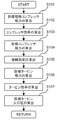
以下、図5を用いて、制御ブロックB33において目標タービン入口圧P1T_trgを算出するフローを説明する。 Hereinafter, a flow for calculating the target turbine inlet pressure P1T_trg in the control block B33 will be described with reference to FIG.
図5において、まず、ステップS101では、目標理論コンプレッサ動力wC_trgを算出する。この目標理論コンプレッサ動力wC_trgは、例えば、以下の数5を用いて算出すると良い。なお、本願発明では、コンプレッサでの圧縮仕事を等エントロピー仕事として、目標吸気圧P1E_trgと目標空気量Ga_trgとから目標理論コンプレッサ動力wC_trgを算出している。以下の式において、Cpaは、吸入空気の定圧比熱、κaは比熱比、T1Cは、図1の吸気温センサ52で計測された吸気温度、Paは、大気圧センサ29で計測された大気圧をそれぞれ意味する。なお、吸入空気の定圧比熱Cpaと、比熱比κaは、予め設定した値を設定すると良い。
In FIG. 5, first, in step S101, a target theoretical compressor power wC_trg is calculated. The target theoretical compressor power wC_trg may be calculated using the following equation 5, for example. In the present invention, the target theoretical compressor power wC_trg is calculated from the target intake pressure P1E_trg and the target air amount Ga_trg with the compression work in the compressor as isentropic work. In the following equation, Cpa is the constant pressure specific heat of the intake air, κa is the specific heat ratio, T1C is the intake air temperature measured by the intake
続いて、ステップS103では、目標コンプレッサ動力WC_trgを算出する。なお、本願発明では、等エントロピー仕事とみなした場合の目標理論コンプレッサ動力wC_trgとコンプレッサ効率ηCとから実際の目標コンプレッサ動力WC_trgを算出している。 Subsequently, in step S103, the target compressor power WC_trg is calculated. In the present invention, the actual target compressor power WC_trg is calculated from the target theoretical compressor power wC_trg and the compressor efficiency ηC when considered as isentropic work.
次に、ステップS105にて、目標タービン動力を算出する。この目標タービン動力WT_trgは、目標コンプレッサ動力WC_trgと機械効率ηmとに基づいて算出することができ、例えば、以下の数7を用いて、算出される。 Next, in step S105, target turbine power is calculated. The target turbine power WT_trg can be calculated based on the target compressor power WC_trg and the mechanical efficiency ηm. For example, the target turbine power WT_trg is calculated using the following formula 7.
また、ステップS107では、目標タービン入口圧を算出する。この目標タービン入口圧P1T_trgは、現在のエンジンから排出された排ガスで目標コンプレッサ動力WT_trgを達成するためのタービン入口の目標圧力である。 In step S107, a target turbine inlet pressure is calculated. This target turbine inlet pressure P1T_trg is a target pressure at the turbine inlet for achieving the target compressor power WT_trg with the exhaust gas discharged from the current engine.
ここで、目標タービン動力は以下の数8で算出することができる。以下の数8において、Cpexは予め決められた排気ガスの定圧比熱、κexは比熱比、T1Tは現在のエンジン運転状態から推定もしくは排気温度センサで測定されたタービン入口温、Gexはタービンを通過する排ガス流量、P2Tは推定されたタービン出口圧を表している。なお、本願発明では、タービン出口圧は、大気圧センサによって検出された大気圧を採用しているが、タービン出口に圧力センサを設け、その圧力センサによって直接圧力を検出しても良い。 Here, the target turbine power can be calculated by the following formula 8. In the following formula 8, Cpex is a predetermined specific pressure specific heat of the exhaust gas, κex is a specific heat ratio, T1T is estimated from the current engine operating state or measured by an exhaust temperature sensor, and Gex passes through the turbine. The exhaust gas flow rate, P2T, represents the estimated turbine outlet pressure. In the present invention, the atmospheric pressure detected by the atmospheric pressure sensor is adopted as the turbine outlet pressure. However, a pressure sensor may be provided at the turbine outlet, and the pressure may be directly detected by the pressure sensor.
以上説明した制御ブロックB33では、目標空気量Ga_trgから目標タービン入口圧P1T_trgが算出される。 In the control block B33 described above, the target turbine inlet pressure P1T_trg is calculated from the target air amount Ga_trg.
続いて、制御ブロックB35では、制御ブロックB33で算出された目標タービン入口圧P1T_trgを達成するための可変翼開度基本位置VN_baseを算出する。このタービン特性は制御ブロックB34で学習補正されたものであり、より精度の高い演算が可能となる。 Subsequently, in the control block B35, a variable blade opening basic position VN_base for achieving the target turbine inlet pressure P1T_trg calculated in the control block B33 is calculated. This turbine characteristic is learned and corrected in the control block B34, and calculation with higher accuracy is possible.
以下、図12を用いて、制御ブロックB35の演算フローを説明する。 Hereinafter, the calculation flow of the control block B35 will be described with reference to FIG.
まず、ステップS301で、タービン入口圧センサ54で測定されたタービン入口圧P1Tと現在のエンジン運転状態から推定もしくは排気温度センサで測定されたタービン入口温をT1T、排気ガス流量Gexから修正排気ガス流量Gex*を算出する。本実施形態では基準温度288K、基準圧力101.325kPaとしている。
First, in step S301, the turbine inlet pressure P1T measured by the turbine
本願発明では、制御ブロックB34で学習補正されたタービン特性(タービン特性図)を学習補正することにより精度良く可変翼開度基本位置VN_baseを算出することができ、この可変翼開度基本位置VN_baseを図3の制御ブロックのフィードフォワード値として使用することにより、より精度の高い制御が可能となる。 In the present invention, the variable blade opening basic position VN_base can be calculated with high accuracy by learning and correcting the turbine characteristic (turbine characteristic diagram) that has been learned and corrected in the control block B34. By using it as the feedforward value of the control block in FIG. 3, more accurate control is possible.
次に、図4の制御ブロックB34における処理について説明する。この制御ブロックB34では、ECU50内に組み込まれているタービン特性が学習補正される。ここで、タービン特性は、前述したように所定のタービン翼開度に対するタービン入口圧とタービン出口圧との膨張比と排気ガス流量との関係を示すものである。つまりは、このタービン特性を用いることで、実際に検出されたタービン入口圧とタービン出口圧との膨張比あるいは運転状態に応じて算出された目標過給圧に基づいて算出されたタービン入口圧とタービン出口圧との膨張比(前述参照)と排気ガス流量とから、実際のタービン翼の開度位置あるいは目標タービン翼の翼開度位置を算出することができる。制御ブロックB34における学習補正は、所定時間毎に実行される。
Next, processing in the control block B34 in FIG. 4 will be described. In this control block B34, the turbine characteristics incorporated in the
図4の制御ブロックB34は、エンジン上でのターボチャージャの運転状態から、ECU50に組み込まれたタービン特性(図11)に基づいて算出されるタービン翼開度VN_cal(以下、「可変翼開度位置」という)と、指令可変翼開度位置VN_trgから算出されるタービン翼開度VN_act(以下、「可変翼開度実位置」という)とを比較し学習補正するものである。なお、指令可変翼開度位置VN_trgは、図3において、可変翼開度基本位置VN_baseとフィードバック量P1E_fbとに基づいて算出されるタービン翼開度である。
The control block B34 in FIG. 4 is a turbine blade opening VN_cal (hereinafter referred to as “variable blade opening position” calculated based on the turbine characteristics (FIG. 11) incorporated in the
以下、図10を用いて、タービン特性の学習するフローを説明する。 Hereinafter, the flow for learning the turbine characteristics will be described with reference to FIG.
まず、ステップS201では、タービンを通過する排気ガス流量Gexを圧力、または温度で補正した修正排気ガス流量Gex*を算出する。この修正排ガス流量Gex*は、例えば、タービン入口圧センサ54で測定されたタービン入口圧P1Tと、タービン入口温度T1Tと、排気ガス流量Gexとから算出すると良い。ここで、タービン入口温度T1Tは、エンジン運転状態から推定しても良いし、排気温度センサを排気管に設け、その排気温度センサによって測定しても良い。また、排気ガス流量Gexは、吸入空気量とエンジン回転速度とから算出すると良い。なお、本実施形態では、基準温度を288K、基準圧力を101.325kPaとしている。
First, in step S201, a corrected exhaust gas flow rate Gex * obtained by correcting the exhaust gas flow rate Gex passing through the turbine with the pressure or temperature is calculated. The corrected exhaust gas flow rate Gex * may be calculated from, for example, the turbine inlet pressure P1T measured by the turbine
ステップS203で、学習補正できる領域にあると判断すると、S204に進み、今回補正する可変翼開度実位置VN_actを算出する。まず、タービン特性は、ECU50内において図11のように格子毎にデータ(マップ)として保管されているので、修正排気ガス流量Gex*と実膨張比πT_actとに該当する格子を検出する。
If it is determined in step S203 that it is in the region where learning correction can be performed, the process proceeds to S204, and the variable blade opening actual position VN_act to be corrected this time is calculated. First, since the turbine characteristics are stored as data (map) for each grid in the
以下の数14を用いて、排気ガス流量Gex(i)と膨張比πT(j)とをそれぞれ算出する。なお、排気ガス流量において、Gex(i)とGex(i+1)との間隔と、膨張比におけるπT(j)とπT(j+1)との間隔は、図9のタービン特性を、図11のように格子毎にデータ(マップ)として、ECU50内に格納する際の分解能で適宜設定すると良い。
Using the following equation 14, the exhaust gas flow rate Gex (i) and the expansion ratio πT (j) are respectively calculated. In addition, in the exhaust gas flow rate, the interval between Gex (i) and Gex (i + 1) and the interval between πT (j) and πT (j + 1) in the expansion ratio are the turbine characteristics of FIG. 9 as shown in FIG. It is preferable to appropriately set the resolution for storing data in the
次に、ステップS206にて、指令可変翼開度位置VN_trgから可変翼作動機構の作動による応答遅れを補正して可変翼開度実位置VN_actを求める。なお、本願発明では、指令可変翼開度位置VN_trgから可変翼作動機構の作動による応答遅れをむだ時間と1次遅れで近似して可変翼開度実位置VN_actを求めている。 Next, in step S206, the response delay due to the operation of the variable blade operating mechanism is corrected from the command variable blade opening position VN_trg to obtain the variable blade opening actual position VN_act. In the present invention, the variable blade opening actual position VN_act is obtained by approximating the response delay due to the operation of the variable blade operating mechanism from the command variable blade opening position VN_trg with the dead time and the first order delay.
続いて、ステップS207にて、下記数15によりタービン特性の可変翼開度データVNijを学習補正する。Kは補正割合である。下記式では、S206で算出した可変翼開度位置VN_calとS205で算出した可変翼開度実位置VN_actとの偏差を、補正割合Kだけ可変翼開度データVNijに学習する。なお、補正係数Kは、定数であっても良いし、学習領域に応じて可変にしても良い。 Subsequently, in step S207, the turbine characteristic variable blade opening degree data NVij is learned and corrected by the following equation (15). K is a correction ratio. In the following formula, the deviation between the variable blade opening position VN_cal calculated in S206 and the variable blade opening actual position VN_act calculated in S205 is learned from the variable blade opening data VAij by a correction ratio K. The correction coefficient K may be a constant or variable depending on the learning area.
なお、本実施形態では、図9のように、膨張比(タービン入口圧÷タービン出口圧)と排気ガス流量とからタービンの翼開度を求めるようにし、図9をタービン特性のマップとしたが、タービン入口圧と排気ガス流量とからタービンの翼開度を求めるようにし、これをタービン特性のマップとしても良い。この場、例えば、タービン出口圧を大気圧とみなすような場合に適用すると良い。また、その他に、タービン動力と排気ガス流量とからタービンの翼開度を求めるようにし、これをタービン特性のマップとしても良い。 In this embodiment, as shown in FIG. 9, the blade opening degree of the turbine is obtained from the expansion ratio (turbine inlet pressure / turbine outlet pressure) and the exhaust gas flow rate, and FIG. 9 is a map of the turbine characteristics. The blade opening degree of the turbine may be obtained from the turbine inlet pressure and the exhaust gas flow rate, and this may be used as a map of the turbine characteristics. In this case, for example, when the turbine outlet pressure is regarded as the atmospheric pressure, it may be applied. In addition, the blade opening degree of the turbine may be obtained from the turbine power and the exhaust gas flow rate, and this may be used as a map of the turbine characteristics.
また、本実施形態では、図9のタービン特性を、ECU50内において図11のように格子毎にデータとして保管されるようにし、各格子を学習補正するように設定したが、学習の対象となる格子付近を補正するようにしても良い。また、格子全体を補正しても良い。
Further, in the present embodiment, the turbine characteristics of FIG. 9 are stored as data for each grid in the
なお、本実施形態では、ディーゼルエンジンを例に挙げて説明したが、ガソリンエンジンに適用しても良い。 In the present embodiment, the diesel engine has been described as an example, but may be applied to a gasoline engine.
10 エンジン
30 ターボチャージャ
31 コンプレッサインペラ
32 タービンホイール
33 シャフト
51 エアフロメータ
52 吸気温センサ
53 可変翼調整機構
B20 フィードバック制御器
B30 フィードフォワード制御器
DESCRIPTION OF
Claims (4)
前記タービンの翼開度(以下、「タービン翼開度」という)を調整する可変翼開度調整機構と、
前記タービンより上流の排気通路の圧力(以下、「タービン入口圧」という)又は該タービン入口圧と相関のあるパラメータからタービン翼開度を算出するマップ(以下、「タービン特性」という)を備え、内燃機関の運転状態に基づいて前記コンプレッサで過給する目標過給圧を算出し、該目標過給圧に基づいて前記タービン入口圧又は該タービン入口圧と相関のあるパラメータを求め、前記タービン特性を用いて前記可変翼調整機構により調整されるタービン翼開度を算出する過給機のモデルを備えた過給機付き内燃機関の制御装置において、
前記過給機のモデルを用いて、内燃機関の運転状態に基づく目標過給圧となるように前記タービンの翼開度(以下、「第1のタービン翼開度」という)を算出する第1のタービン翼開度算出手段と、
実際のタービン入口圧(以下、「実タービン入口圧」という)を検出し、前記実タービン入口圧又は該実タービン入口圧と相関のあるパラメータから前記タービン特性を用いて、前記タービンの翼開度(以下、「第2のタービン翼開度」という)を算出する第2のタービン翼開度算出手段とを備え、
前記第2のタービン翼開度算出手段により算出された第2のタービン翼開度と前記第1のタービン翼開度算出手段により算出された第1のタービン翼開度とに基づいて、前記タービン特性を補正する学習補正手段を備えることを特徴とする過給機付き内燃機関の制御装置。 A turbocharger that drives a compressor provided in the intake passage by driving a turbine provided in the exhaust passage of the internal combustion engine with exhaust pressure to supercharge air into the cylinder;
A variable blade opening adjustment mechanism for adjusting the blade opening of the turbine (hereinafter referred to as “turbine blade opening”);
A map (hereinafter referred to as “turbine characteristics”) for calculating the turbine blade opening from the pressure in the exhaust passage upstream from the turbine (hereinafter referred to as “turbine inlet pressure”) or a parameter correlated with the turbine inlet pressure; Calculating a target supercharging pressure to be supercharged by the compressor based on an operating state of the internal combustion engine, obtaining a turbine inlet pressure or a parameter correlated with the turbine inlet pressure based on the target supercharging pressure; In a control device for an internal combustion engine with a supercharger equipped with a supercharger model for calculating a turbine blade opening adjusted by the variable blade adjustment mechanism using
First, the blade opening degree of the turbine (hereinafter referred to as “first turbine blade opening degree”) is calculated using the turbocharger model so as to achieve a target supercharging pressure based on the operating state of the internal combustion engine. Turbine blade opening degree calculation means,
An actual turbine inlet pressure (hereinafter referred to as “actual turbine inlet pressure”) is detected, and the blade opening degree of the turbine is determined using the turbine characteristics from the actual turbine inlet pressure or a parameter correlated with the actual turbine inlet pressure. (Hereinafter referred to as “second turbine blade opening”) and second turbine blade opening calculation means for calculating,
Based on the second turbine blade opening calculated by the second turbine blade opening calculating means and the first turbine blade opening calculated by the first turbine blade opening calculating means, the turbine A control apparatus for an internal combustion engine with a supercharger, comprising learning correction means for correcting characteristics.
前記学習補正手段は、前記第2のタービン翼開度算出手段により算出された第2のタービン翼開度と前記補正手段により補正された前記第1のタービン翼開度とに基づいて、前記タービン特性を補正することを特徴とする請求項1に記載の過給機付き内燃機関の制御装置。 The first turbine blade opening degree calculating means includes a correcting means for correcting the first turbine blade opening degree calculated by the first turbine blade opening degree calculating means with a dead time and a first order lag.
The learning correction means is configured to generate the turbine based on the second turbine blade opening calculated by the second turbine blade opening calculation means and the first turbine blade opening corrected by the correction means. The control apparatus for an internal combustion engine with a supercharger according to claim 1, wherein the characteristic is corrected.
The parameter correlated with the turbine inlet pressure is an expansion ratio between the turbine inlet pressure and the turbine outlet pressure (hereinafter referred to as “turbine outlet pressure”), or the power of the turbine (hereinafter referred to as “turbine power”). control device for an internal combustion engine with a supercharger according to any one of claims 1 to 3, characterized in that) it is.
Priority Applications (1)
| Application Number | Priority Date | Filing Date | Title |
|---|---|---|---|
| JP2007327430A JP4853471B2 (en) | 2007-12-19 | 2007-12-19 | Control device for an internal combustion engine with a supercharger |
Applications Claiming Priority (1)
| Application Number | Priority Date | Filing Date | Title |
|---|---|---|---|
| JP2007327430A JP4853471B2 (en) | 2007-12-19 | 2007-12-19 | Control device for an internal combustion engine with a supercharger |
Publications (3)
| Publication Number | Publication Date |
|---|---|
| JP2009150267A JP2009150267A (en) | 2009-07-09 |
| JP2009150267A5 JP2009150267A5 (en) | 2011-10-20 |
| JP4853471B2 true JP4853471B2 (en) | 2012-01-11 |
Family
ID=40919663
Family Applications (1)
| Application Number | Title | Priority Date | Filing Date |
|---|---|---|---|
| JP2007327430A Expired - Fee Related JP4853471B2 (en) | 2007-12-19 | 2007-12-19 | Control device for an internal combustion engine with a supercharger |
Country Status (1)
| Country | Link |
|---|---|
| JP (1) | JP4853471B2 (en) |
Families Citing this family (6)
| Publication number | Priority date | Publication date | Assignee | Title |
|---|---|---|---|---|
| EP2339153B1 (en) | 2009-12-23 | 2019-10-16 | FPT Motorenforschung AG | Method and apparatus for measuring and controlling the egr rate in a combustion engine |
| FR2988774B1 (en) * | 2012-03-28 | 2015-10-02 | Renault Sa | SYSTEM FOR CONTROLLING THE FINS OF A VARIABLE GEOMETRY TURBINE WITH LEARNING AND LINEARIZATION |
| JP6026211B2 (en) * | 2012-10-11 | 2016-11-16 | 日野自動車株式会社 | Turbocharger control device and control method |
| KR101382321B1 (en) | 2012-12-17 | 2014-04-08 | 기아자동차 주식회사 | Method of compensating position change of vane of variable geometry turbocharger |
| JP6513440B2 (en) * | 2015-03-19 | 2019-05-15 | 日野自動車株式会社 | Controller of variable displacement turbocharger |
| CN113738519B (en) * | 2021-10-12 | 2022-08-02 | 上海交通大学 | Diesel engine variable altitude self-adaptive energy regulation and control method |
Family Cites Families (6)
| Publication number | Priority date | Publication date | Assignee | Title |
|---|---|---|---|---|
| JP2519190B2 (en) * | 1987-12-29 | 1996-07-31 | 本田技研工業株式会社 | Control method for boost pressure of internal combustion engine |
| JP4320859B2 (en) * | 1998-11-27 | 2009-08-26 | マツダ株式会社 | Control device for turbocharged engine |
| JP2001082158A (en) * | 1999-09-17 | 2001-03-27 | Mazda Motor Corp | Control device for engine with supercharger |
| EP1299628B1 (en) * | 2000-07-07 | 2006-08-02 | Siemens Aktiengesellschaft | Method for controlling a charge pressure in an internal combustion engine with an exhaust-gas turbocharger |
| JP2006097542A (en) * | 2004-09-29 | 2006-04-13 | Nissan Motor Co Ltd | Supercharging pressure regulating device of variable supercharging system |
| JP2007187065A (en) * | 2006-01-12 | 2007-07-26 | Toyota Motor Corp | Engine-learning control device |
-
2007
- 2007-12-19 JP JP2007327430A patent/JP4853471B2/en not_active Expired - Fee Related
Also Published As
| Publication number | Publication date |
|---|---|
| JP2009150267A (en) | 2009-07-09 |
Similar Documents
| Publication | Publication Date | Title |
|---|---|---|
| US10815918B2 (en) | Controller and control method for supercharger-equipped internal combustion engine | |
| JP4306703B2 (en) | Control device for an internal combustion engine with a supercharger | |
| US7805939B2 (en) | Controller for internal combustion engine with supercharger | |
| US9261031B2 (en) | Control device for internal combustion engine and method for controlling internal combustion engine | |
| US20060207252A1 (en) | Controller for internal combustion engine with supercharger | |
| US7047740B2 (en) | Boost pressure estimation apparatus for internal combustion engine with supercharger | |
| JP4378700B2 (en) | Control device for an internal combustion engine with a supercharger | |
| JP4375369B2 (en) | Control device for an internal combustion engine with a supercharger | |
| KR101548908B1 (en) | Method and device for the operation of an internal combustion engine comprising an exhaust gas turbocharger | |
| JP5389238B1 (en) | Waste gate valve control device for internal combustion engine | |
| US11002197B2 (en) | Control device for internal combustion engine | |
| JP4853471B2 (en) | Control device for an internal combustion engine with a supercharger | |
| JP4378701B2 (en) | Control device for an internal combustion engine with a supercharger | |
| US20140363278A1 (en) | Variable geometry turbocharger control system | |
| JP2006242063A (en) | Control device for internal combustion engine with supercharger | |
| JP2006152821A (en) | Control system of internal combustion engine with supercharger | |
| JP2009168007A (en) | Control device for internal combustion engine with supercharger | |
| JP2006152932A (en) | Controller of internal combustion engine | |
| JP4542489B2 (en) | Exhaust manifold internal temperature estimation device for internal combustion engine | |
| CN110821647B (en) | Method and device for operating an internal combustion engine with charge pressure regulation | |
| EP2354501B1 (en) | Control apparatus for internal combustion engine | |
| JP6351784B1 (en) | Control device for internal combustion engine and control method for internal combustion engine | |
| JP3726588B2 (en) | Control device for internal combustion engine | |
| WO2022024203A1 (en) | Supercharging pressure control method and supercharging pressure control device for internal combustion engine | |
| JP6453122B2 (en) | Control device for variable capacity turbocharger |
Legal Events
| Date | Code | Title | Description |
|---|---|---|---|
| A621 | Written request for application examination |
Free format text: JAPANESE INTERMEDIATE CODE: A621 Effective date: 20100831 |
|
| A977 | Report on retrieval |
Free format text: JAPANESE INTERMEDIATE CODE: A971007 Effective date: 20110825 |
|
| A521 | Request for written amendment filed |
Free format text: JAPANESE INTERMEDIATE CODE: A523 Effective date: 20110906 |
|
| TRDD | Decision of grant or rejection written | ||
| A01 | Written decision to grant a patent or to grant a registration (utility model) |
Free format text: JAPANESE INTERMEDIATE CODE: A01 Effective date: 20110927 |
|
| A01 | Written decision to grant a patent or to grant a registration (utility model) |
Free format text: JAPANESE INTERMEDIATE CODE: A01 |
|
| A61 | First payment of annual fees (during grant procedure) |
Free format text: JAPANESE INTERMEDIATE CODE: A61 Effective date: 20111010 |
|
| FPAY | Renewal fee payment (event date is renewal date of database) |
Free format text: PAYMENT UNTIL: 20141104 Year of fee payment: 3 |
|
| R151 | Written notification of patent or utility model registration |
Ref document number: 4853471 Country of ref document: JP Free format text: JAPANESE INTERMEDIATE CODE: R151 |
|
| FPAY | Renewal fee payment (event date is renewal date of database) |
Free format text: PAYMENT UNTIL: 20141104 Year of fee payment: 3 |
|
| R250 | Receipt of annual fees |
Free format text: JAPANESE INTERMEDIATE CODE: R250 |
|
| R250 | Receipt of annual fees |
Free format text: JAPANESE INTERMEDIATE CODE: R250 |
|
| R250 | Receipt of annual fees |
Free format text: JAPANESE INTERMEDIATE CODE: R250 |
|
| R250 | Receipt of annual fees |
Free format text: JAPANESE INTERMEDIATE CODE: R250 |
|
| R250 | Receipt of annual fees |
Free format text: JAPANESE INTERMEDIATE CODE: R250 |
|
| R250 | Receipt of annual fees |
Free format text: JAPANESE INTERMEDIATE CODE: R250 |
|
| R250 | Receipt of annual fees |
Free format text: JAPANESE INTERMEDIATE CODE: R250 |
|
| LAPS | Cancellation because of no payment of annual fees |