JP4850919B2 - Optical receiver - Google Patents
Optical receiver Download PDFInfo
- Publication number
- JP4850919B2 JP4850919B2 JP2008550020A JP2008550020A JP4850919B2 JP 4850919 B2 JP4850919 B2 JP 4850919B2 JP 2008550020 A JP2008550020 A JP 2008550020A JP 2008550020 A JP2008550020 A JP 2008550020A JP 4850919 B2 JP4850919 B2 JP 4850919B2
- Authority
- JP
- Japan
- Prior art keywords
- time constant
- circuit
- signal
- optical receiver
- output
- Prior art date
- Legal status (The legal status is an assumption and is not a legal conclusion. Google has not performed a legal analysis and makes no representation as to the accuracy of the status listed.)
- Active
Links
Images


Classifications
-
- H—ELECTRICITY
- H04—ELECTRIC COMMUNICATION TECHNIQUE
- H04B—TRANSMISSION
- H04B10/00—Transmission systems employing electromagnetic waves other than radio-waves, e.g. infrared, visible or ultraviolet light, or employing corpuscular radiation, e.g. quantum communication
- H04B10/60—Receivers
-
- H—ELECTRICITY
- H03—ELECTRONIC CIRCUITRY
- H03G—CONTROL OF AMPLIFICATION
- H03G3/00—Gain control in amplifiers or frequency changers without distortion of the input signal
- H03G3/20—Automatic control
- H03G3/30—Automatic control in amplifiers having semiconductor devices
- H03G3/3084—Automatic control in amplifiers having semiconductor devices in receivers or transmitters for electromagnetic waves other than radiowaves, e.g. lightwaves
-
- H—ELECTRICITY
- H04—ELECTRIC COMMUNICATION TECHNIQUE
- H04B—TRANSMISSION
- H04B10/00—Transmission systems employing electromagnetic waves other than radio-waves, e.g. infrared, visible or ultraviolet light, or employing corpuscular radiation, e.g. quantum communication
-
- H—ELECTRICITY
- H04—ELECTRIC COMMUNICATION TECHNIQUE
- H04B—TRANSMISSION
- H04B10/00—Transmission systems employing electromagnetic waves other than radio-waves, e.g. infrared, visible or ultraviolet light, or employing corpuscular radiation, e.g. quantum communication
- H04B10/25—Arrangements specific to fibre transmission
- H04B10/2581—Multimode transmission
-
- H—ELECTRICITY
- H04—ELECTRIC COMMUNICATION TECHNIQUE
- H04B—TRANSMISSION
- H04B10/00—Transmission systems employing electromagnetic waves other than radio-waves, e.g. infrared, visible or ultraviolet light, or employing corpuscular radiation, e.g. quantum communication
- H04B10/60—Receivers
- H04B10/66—Non-coherent receivers, e.g. using direct detection
- H04B10/69—Electrical arrangements in the receiver
- H04B10/693—Arrangements for optimizing the preamplifier in the receiver
- H04B10/6931—Automatic gain control of the preamplifier
-
- H—ELECTRICITY
- H04—ELECTRIC COMMUNICATION TECHNIQUE
- H04B—TRANSMISSION
- H04B10/00—Transmission systems employing electromagnetic waves other than radio-waves, e.g. infrared, visible or ultraviolet light, or employing corpuscular radiation, e.g. quantum communication
- H04B10/60—Receivers
- H04B10/66—Non-coherent receivers, e.g. using direct detection
- H04B10/69—Electrical arrangements in the receiver
- H04B10/695—Arrangements for optimizing the decision element in the receiver, e.g. by using automatic threshold control
Description
この発明は、光通信システムに関するものであり、特に、アクセス系光通信システムの一つであるPON(Passive Optical Network)システムに適用される光受信器に関するものである。 The present invention relates to an optical communication system, and more particularly to an optical receiver applied to a PON (Passive Optical Network) system which is one of access optical communication systems.
従来、光ファイバを用いた公衆回線網を実現するシステムとして、PON(Passive Optical Network)システムと呼ばれるポイント・トゥ・マルチポイントのアクセス系光通信システムが広く用いられている。 2. Description of the Related Art Conventionally, a point-to-multipoint access optical communication system called a PON (Passive Optical Network) system has been widely used as a system for realizing a public line network using optical fibers.
PONシステムは、局側装置である1台のOLT(Optical Line Terminal)と、光スターカプラを介して接続される複数の加入者端末装置であるONU(Optical Network Unit)とにより構成される。多数のONUに対して、OLTと伝送路である光ファイバの大部分は共有できるため運用コストの経済化が期待できることや、受動部品である光スターカプラには給電が必要なく屋外設置が容易であり、信頼性も高いという利点があることから、ブロードバンドネットワークを実現する切り札として近年活発に導入が進められている。 The PON system is composed of one OLT (Optical Line Terminal) which is a station side device and an ONU (Optical Network Unit) which is a plurality of subscriber terminal devices connected via an optical star coupler. For many ONUs, most of the optical fiber, which is the transmission line, can be shared with the OLT, so that the operating cost can be expected to be economical, and the optical star coupler, which is a passive component, does not require power supply and can be installed outdoors. Since it has the advantage of high reliability, it has been actively introduced as a trump card for realizing a broadband network in recent years.
例えば、IEEE802.3ahで規格化されている伝送速度が1.25Gbit/sのGE−PON(Gigabit Ethernet - Passive Optical Network)においては、OLTからONUへの下りは、光波長1.49μm帯を用いた同報通信方式を用い、各ONUは割り当てられたタイムスロットのデータのみ取り出す。一方、各ONUからOLTへの上りは、光波長1.31μm帯を用い、各ONUのデータが衝突しないように送出タイミングを制御する時分割多重通信方式を用いている。 For example, in a GE-PON (Gigabit Ethernet-Passive Optical Network) with a transmission rate of 1.25 Gbit / s standardized by IEEE802.3ah, the optical wavelength 1.49 μm band is used for the downlink from the OLT to the ONU. Each ONU extracts only the data of the assigned time slot using the broadcast communication method. On the other hand, ascending from each ONU to the OLT uses the optical wavelength band of 1.31 μm, and uses a time division multiplex communication system that controls transmission timing so that data of each ONU does not collide.
上記のようなPONシステムの上り方向の通信においては、各ONUは光スターカプラから異なる距離に位置することから、OLTにおける各ONUの受信レベルは受信パケット毎に異なるため、OLTの受信回路には異なる受光レベルのパケットを安定に再生する広ダイナミックレンジ特性を必要とする。従って、一般的に、OLTの受信回路には、受光レベルに応じて変換利得を変化させるAGC(Automatic Gain Control)回路が備えられており、AGCの高速応答性と同符号連続耐力との両立が求められている。 In the upstream communication of the PON system as described above, since each ONU is located at a different distance from the optical star coupler, the reception level of each ONU in the OLT is different for each received packet. A wide dynamic range characteristic that stably reproduces packets of different received light levels is required. Therefore, in general, the OLT receiving circuit is provided with an AGC (Automatic Gain Control) circuit that changes the conversion gain in accordance with the received light level, and it is possible to achieve both AGC high-speed response and continuous proof strength of the same sign. It has been demanded.
AGC回路には様々な方式が提案されているが、例えば特許文献1においては、受光レベルに応じて前置増幅器の帰還抵抗値、すなわち変換利得を段階的に切り替えている。また、特許文献1で参照している従来技術である特許文献2においては、受光レベルに応じて前置増幅器の帰還抵抗値、すなわち変換利得をアナログ的に変化させている。
Various methods have been proposed for the AGC circuit. For example, in Patent Document 1, the feedback resistance value of the preamplifier, that is, the conversion gain is switched stepwise in accordance with the light reception level. In
上記特許文献1に示された技術では、パケットの先頭数ビットでAGC動作が完了し、また、AGC動作完了後は受信信号のパターン列に依らず常に一定の利得が保たれるため、高速応答性と同符号連続耐力とを両立できる利点を有している。しかしながら、一方では、パケットの先頭ビットの振幅に応じて利得制御する方式であるため、受信するバースト信号が過渡的にレベル変動する場合、特に、過剰発光後に一定レベルに収束するような場合には、誤った変換利得に切り替えてしまうという問題がある。 In the technique disclosed in Patent Document 1, the AGC operation is completed with the first few bits of the packet, and after the AGC operation is completed, a constant gain is always maintained regardless of the pattern sequence of the received signal. And the same sign continuous proof stress can be achieved. However, on the other hand, since the gain is controlled according to the amplitude of the first bit of the packet, the level of the received burst signal changes transiently, particularly when it converges to a certain level after excessive light emission. There is a problem of switching to an incorrect conversion gain.
また、上記特許文献2に示された技術では、高速応答性を実現するためにはAGCループの時定数を短くする必要があるが、この場合、変換利得が受信信号のパターン列に依存しやすくなり、同符号連続耐力が劣化することとなる。すなわち、高速応答性と同符号連続耐力を両立することが困難であるという問題がある。
In the technique disclosed in
この発明は上述した点に鑑みてなされたもので、主にアクセス系光通信システムの一つであるPONシステムにおいて、異なる受光レベルのバースト信号を安定に再生する広ダイナミックレンジ特性を有し、かつ高速応答性と同符号連続耐力に優れた光受信器を提供することを目的とするものである。 The present invention has been made in view of the above points, and has a wide dynamic range characteristic for stably reproducing burst signals of different received light levels in a PON system which is one of access optical communication systems, and An object of the present invention is to provide an optical receiver excellent in high-speed response and continuous resistance to the same sign.
この発明に係る光受信器は、受信した光信号の受光レベルに応じた電流を出力する受光素子と、前記受光素子からの出力電流信号を電圧信号に変換するプリアンプと、時定数の短い第1のレベル検出部と、前記第1のレベル検出部の時定数よりも長い時定数を有する第2のレベル検出部とを有し、時定数切替信号に基づいて前記第1のレベル検出部または前記第2のレベル検出部のいずれかに切り替えられて、前記プリアンプが出力する出力電圧信号の電圧レベルを検出するレベル検出手段と、前記レベル検出手段の検出結果に基づいて前記プリアンプの変換利得を可変制御する変換利得制御手段と、前記プリアンプからの出力電圧信号に基づいて時定数切替信号を出力する時定数切替制御手段とを備え、前記時定数切替制御手段は、受信されるバースト信号のパケットのビット列の同符号連続数が所定数より小さい場合は前記第1のレベル検出部を選択し、所定数以上の場合に前記第2のレベル検出部を選択すべく、前記レベル検出手段に時定数切替信号を出力する。 An optical receiver according to the present invention includes a light receiving element that outputs a current according to a received light level of a received optical signal, a preamplifier that converts an output current signal from the light receiving element into a voltage signal, and a first having a short time constant. And a second level detection unit having a time constant longer than the time constant of the first level detection unit, and the first level detection unit or the above-mentioned level detection unit based on a time constant switching signal Switched to one of the second level detection units, level detection means for detecting the voltage level of the output voltage signal output from the preamplifier, and variable conversion gain of the preamplifier based on the detection result of the level detection means Conversion gain control means for controlling, and time constant switching control means for outputting a time constant switching signal based on an output voltage signal from the preamplifier, wherein the time constant switching control means is received. The first level detector is selected when the number of consecutive same-code symbols in a burst signal packet is smaller than a predetermined number, and the second level detector is selected when the number is equal to or greater than the predetermined number. A time constant switching signal is output to the detecting means.
この発明によれば、変換利得を変えることが可能なプリアンプと、時定数を切り替えることが可能なレベル検出手段と、受信信号をもとに適切な時定数を選択する時定数切替制御手段とを備え、時定数切替制御手段の時定数切替信号に基づいて、バースト信号のパケット先頭部ではレベル検出手段の時定数が短くなるように制御し、プリアンプのAGC動作完了後にはレベル検出手段の時定数が長くなるように制御し、さらに、上記のように制御されたレベル検出手段の検出結果に基づいてプリアンプの変換利得を制御するため、異なる受光レベルのパケットを安定に再生する広ダイナミックレンジ特性を有し、かつ高速応答性と同符号連続耐力に優れた光受信器を実現できる。 According to the present invention, the preamplifier capable of changing the conversion gain, the level detection means capable of switching the time constant, and the time constant switching control means for selecting an appropriate time constant based on the received signal. A time constant switching control means for controlling the time constant of the level detection means to be short at the beginning of the packet of the burst signal based on the time constant switching signal of the time constant switching control means, and the time constant of the level detection means after completion of the AGC operation of the preamplifier. In order to control the conversion gain of the preamplifier based on the detection result of the level detection means controlled as described above, a wide dynamic range characteristic that stably reproduces packets of different received light levels is provided. It is possible to realize an optical receiver that has high-speed response and excellent continuous strength with the same sign.
以下、添付図面を参照して、この発明の実施の形態に係る光受信器を詳細に説明する。なお、この発明は実施の形態により限定されるものではない。 Hereinafter, an optical receiver according to an embodiment of the present invention will be described in detail with reference to the accompanying drawings. In addition, this invention is not limited by embodiment.
実施の形態1.
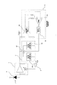
図1は、この発明の実施の形態1に係る光受信器の構成を示すブロック図である。受光素子1は、カソードが電源に接続され、アノードがプリアンプ2の入力端に接続され、受信した光信号の受光レベルに応じた電流を出力する。プリアンプ2は、受光素子1から入力された電流を電圧に変換して出力し、かつ、入力される制御電圧により、電流を電圧に変換する変換効率を変化できる。Embodiment 1 FIG.
1 is a block diagram showing a configuration of an optical receiver according to Embodiment 1 of the present invention. The light receiving element 1 has a cathode connected to a power source and an anode connected to the input terminal of the
プリアンプ2から出力される電圧信号は、レベル検出回路3によりその平均値が検出される。このレベル検出回路3は、時定数が短いレベル検出部31と、レベル検出部31の時定数よりも長い時定数を有する、時定数が長いレベル検出部32と、レベル検出回路3の時定数を切り替えるための時定数切り替えスイッチ33とによって構成される。
The average value of the voltage signal output from the
レベル検出回路3の出力電圧は、変換利得制御手段としての増幅器4によって所望の制御電圧に増幅され、プリアンプ2の変換利得を制御する。また、時定数切替制御回路5は、プリアンプ2から出力される受信電気信号に基づいて適切な時定数を選択するものであり、受信されるバースト信号のパケットのビット列の同符号連続数が所定数より小さい場合は前記第1のレベル検出部を選択し、所定数以上の場合に前記第2のレベル検出部を選択すべく、時定数切替信号を時定数切り替えスイッチ33に入力する。
The output voltage of the
なお、レベル検出回路3の時定数切り替えスイッチ33は、AGC動作中には、時定数が短いレベル検出部33側と接続し、AGC動作完了時には、時定数が長いレベル検出部33と接続するように動作する。
The time
次に、図2に、図1の各部の信号波形を示すタイミングチャートを示す。(A)は受光素子1の出力電流、(B)はプリアンプ2の出力電圧、(C)は常に時定数が短いレベル検出部31を用いた場合のレベル検出回路3の出力電圧、(D)は常に時定数が長いレベル検出部32を用いた場合のレベル検出回路3の出力電圧、(E)は時定数切替制御回路5の検出結果に基づいて時定数切り替えスイッチ33を切り替えた場合のレベル検出回路3の出力電圧、(F)は時定数切替制御回路5から出力される時定数切替信号をそれぞれ示している。なお、図2において、(C)、(D)、(E)については、プリアンプ2の出力電圧との関係を明確化するために、(B)に重ねて表示している。
Next, FIG. 2 shows a timing chart showing signal waveforms of respective parts in FIG. (A) is the output current of the light receiving element 1, (B) is the output voltage of the
この発明の実施の形態1に係る光受信器の動作および特徴について図2を参照して説明する。図2において、(C)は、常に時定数が短いレベル検出部31を用いた場合のレベル検出回路3の出力電圧であり、時定数が短いため高速応答性に優れる反面、同符号が連続する場合にはレベル検出誤差が大きくなり、所望の変換利得に一定制御することが困難となる。
The operation and characteristics of the optical receiver according to Embodiment 1 of the present invention will be described with reference to FIG. In FIG. 2, (C) is the output voltage of the
一方、図2において、(D)は、常に時定数が長いレベル検出部32を用いた場合のレベル検出回路3の出力電圧であり、時定数が長いため同符号が連続する場合であっても精度良くレベル検出でき、所望の変換利得に一定制御可能である反面、高速応答性に難があるため、バースト受信用には不向きである。
On the other hand, in FIG. 2, (D) is an output voltage of the
図2において、(E)は、時定数切替制御回路5の出力電圧に基づいて、レベル検出回路3を構成する時定数切り替えスイッチ33により、レベル検出回路3の時定数を切り替えた場合のレベル検出回路3の出力電圧であり、バースト信号のパケットの先頭でのみ短い時定数で、それ以降は長い時定数でレベル検出を行う。
In FIG. 2, (E) shows the level detection when the time constant of the
一般的に、バースト信号のパケットは、送受信器間のデータ伝送で必要な同期を確立するためにパケットの先頭に付加されるプリアンブル部と、実際の通信データを格納するデータ部とで構成されており、それぞれに許容されるビット列の最大同符号連続数は、プリアンブル部よりもデータ部の方が大きい。 In general, a burst signal packet is composed of a preamble part added to the head of the packet to establish synchronization necessary for data transmission between the transmitter and the receiver, and a data part for storing actual communication data. Thus, the maximum number of consecutive same-symbols allowed for each bit string is larger in the data part than in the preamble part.
従って、パケット先頭のプリアンブル部において、AGC動作が完了するまでは短い時定数でレベル検出することにより高速にAGC動作を完了し、AGC動作完了後にレベル検出を長い時定数に切り替えることにより、長い同符号連続ビット列を含むデータ部においても精度良く安定したレベル検出が可能となる。 Therefore, in the preamble portion at the beginning of the packet, the AGC operation is completed at a high speed by detecting the level with a short time constant until the AGC operation is completed, and the level detection is switched to a long time constant after the AGC operation is completed. Even in the data portion including the code continuous bit string, it is possible to detect the level with high accuracy and stability.
このように、この発明の実施の形態1に係る光受信器においては、変換利得を変えることが可能なプリアンプ2と、時定数を切り替えることが可能なレベル検出回路3と、受信信号をもとに適切な時定数を選択する時定数切替制御回路5とを備え、時定数切替制御回路5の検出結果に基づいて、バースト信号のパケット先頭部ではレベル検出回路3の時定数が短くなるように制御し、プリアンプ2のAGC動作完了後にはレベル検出回路3の時定数が長くなるように制御し、さらに、上記のように制御されたレベル検出回路3の検出結果に基づいてプリアンプ2の変換利得を制御するため、異なる受光レベルのパケットを安定に再生する広ダイナミックレンジ特性を有し、かつ高速応答性と同符号連続耐力に優れた光受信器を実現できる。
As described above, in the optical receiver according to the first embodiment of the present invention, the
実施の形態2.
図3は、この発明の実施の形態2に係る光受信器の構成を示すブロック図である。図3に示す実施の形態2の構成において、図1に示す実施の形態1の構成と同一部分は同一符号を付してその説明は省略する。実施の形態1と異なる点は、時定数切替制御回路5の構成が異なる。図3に示す実施の形態2の構成において、時定数切替制御回路5は、収束状態判定回路51と、収束状態判定回路51の判定結果をもとに時定数切替信号を生成する時定数切替信号生成ロジック回路52により構成されている。
FIG. 3 is a block diagram showing a configuration of an optical receiver according to
図4は、収束状態判定回路51と、時定数切替信号生成ロジック回路52の具体的な構成例を示すブロック図である。収束状態判定回路51は、入力段に平均値検出回路511を備え、その後段に微分回路512、さらに差動増幅回路513を備えている。また、時定数切替信号生成ロジック回路52は、収束状態判定回路51の出力段に備えられる差動増幅回路513のそれぞれの出力信号を入力とする二つの比較器521、522を入力段に備え、比較器521と522の出力をAND論理回路523により論理演算し、その結果を出力する。なお、平均値検出回路511の時定数は、レベル検出回路3の短いレベル検出部31の時定数と同等である。
FIG. 4 is a block diagram illustrating a specific configuration example of the convergence
次に、図5に、図4の各部の信号波形を示すタイミングチャートを示す。図5において、(A)は平均値検出回路511の入力信号、(B)は平均値検出回路511の出力信号、(C)は微分回路512の出力信号、(D)は差動増幅回路513に入力される基準電圧信号、(E)と(F)はそれぞれ差動増幅回路513の出力信号、(G)と(H)はそれぞれ比較器521、522の基準電圧信号、(I)は比較器521の出力信号、(J)は比較器522の出力信号、(K)はAND論理回路523の出力信号を示している。
Next, FIG. 5 shows a timing chart showing signal waveforms of respective parts in FIG. 5, (A) is an input signal of the average
図5を用いて、この発明の実施の形態2に係る光受信器の動作および特徴について説明する。
The operation and characteristics of the optical receiver according to
図5において、平均値検出回路511の出力信号(B)が変化している場合、すわなち、一定電圧に収束していない過渡状態にのみ、微分回路512の出力信号(C)は、平均値検出回路511の出力信号(B)の時間的な変化率に応じた振幅を出力する。ここで、差動増幅回路513の基準電圧信号(D)の電圧値を、平均値検出回路511の出力信号(B)が収束している場合の微分回路512の出力信号(C)の出力値と等しくし、差動増幅回路513により微分回路512の出力信号(C)を増幅している。また、比較器521と522の基準電圧信号(G)と(H)の電圧値は、平均値検出回路511の出力信号(B)が収束している場合の差動増幅回路513の出力電圧信号(E)と(F)の電圧値と等しくしている。
In FIG. 5, when the output signal (B) of the average
従って、平均値検出回路511の出力信号(B)が過渡状態であり、かつ減少時には、比較器521の出力信号(I)はHighレベルの信号を出力し、平均値検出回路511の出力信号(B)が過渡状態であり、かつ増加時には、比較器522の出力信号(J)はHighレベルの信号を出力するよう動作する。比較器521と522の出力信号(I)と(J)をAND論理回路523によりAND演算するため、平均値検出回路511の出力信号(B)が一定電圧に収束していない過渡状態には、平均値検出回路511の出力信号(B)が減少時、増加時、いずれの状態であっても、時定数切替制御回路5は、Highレベルの信号を出力するよう動作する。
Accordingly, when the output signal (B) of the average
また、図6は、図4とは異なる収束状態判定回路51と、時定数切替信号生成ロジック回路52の具体的な構成例を示すブロック図である。なお、時定数切替信号生成ロジック回路52については、図4に示す例と等しいため説明を割愛する。図6において、収束状態判定回路51は、入力段に時定数が異なる二つの平均値検出回路514と515を備え、その後段に差動増幅回路516を備えている。ここで、平均値検出回路515の時定数は平均値検出回路514の時定数よりも短いものとする。また、平均値検出回路514の時定数は、レベル検出回路3の短いレベル検出部31の時定数と同等である。
FIG. 6 is a block diagram showing a specific configuration example of a convergence
次に、図7に、図6の各部の信号波形を示すタイミングチャートを示す。図7において、(A)は平均値検出回路514および515の入力信号、(B)は平均値検出回路514の出力信号、(C)は平均値検出回路515の出力信号、(D)と(E)はそれぞれ差動増幅回路516の出力信号を示している。
Next, FIG. 7 shows a timing chart showing signal waveforms of respective parts in FIG. 7, (A) is an input signal of average
図7を用いて、この発明の実施の形態2に係る光受信器の動作および特徴について説明する。 The operation and characteristics of the optical receiver according to the second embodiment of the present invention will be described with reference to FIG.
平均値検出回路514の時定数は、平均値検出回路515の時定数よりも長いため、図7において、平均値検出回路514の出力信号(B)の収束時間は平均値検出回路515の出力信号(C)の収束時間よりも遅く、タイムラグが生じる。平均値検出回路514の出力信号(B)と平均値検出回路515の出力信号(C)とを入力信号とする差動増幅回路516は、平均値検出回路514の出力信号(B)と平均値検出回路515の出力信号(C)に電位差がある場合、すなわち、平均値検出回路514の出力信号(B)が一定電圧に収束していない過渡状態にのみ、平均値検出回路514の出力信号(B)と平均値検出回路515の出力信号(C)の電位差に応じた振幅を出力する。時定数切替信号生成ロジック回路52は、前述と同様の動作をするため、平均値検出回路514の出力信号(B)が一定電圧に収束していない過渡状態には、平均値検出回路514の出力信号(B)が減少時、増加時、いずれの状態であっても、Highレベルの信号を出力するよう動作する。
Since the time constant of the average
このように、この発明の実施の形態2に係る光受信器においては、収束状態判定回路51により、レベル検出回路3の時定数で決まるAGC動作の収束状態を判定できるため、AGC動作が収束していない場合には短い時定数によるレベル検出、AGC動作が収束後は長い時定数によるレベル検出とする切替制御が可能となり、異なる受光レベルのパケットを安定に再生する広ダイナミックレンジ特性を有し、かつ高速応答性と同符号連続耐力に優れた光受信器を実現できる。
Thus, in the optical receiver according to
実施の形態3.
図8は、この発明の実施の形態3に係る光受信器の構成を示すブロック図である。図8に示す実施の形態3の構成において、図1に示す実施の形態1及び図3に示す実施の形態2の構成と同一部分は同一符号を付してその説明は省略する。図8に示す実施の形態3の構成が実施の形態1及び2と異なる点は、時定数切替制御回路5の構成が異なる。図8に示す実施の形態3の構成において、時定数切替制御回路5は、プリアンプ2から出力される電圧信号と、レベル検出回路3から出力される電圧信号とを入力とする比較器53と、比較器53から出力される電圧信号の変化点数をカウントする変化点カウンタ54により構成される。
FIG. 8 is a block diagram showing a configuration of an optical receiver according to
次に、図9に、図8の各部の信号波形を示すタイミングチャートを示す。図9において、(A)はプリアンプ2の出力信号、(B)はレベル検出回路3の出力信号、(C)は比較器53の出力信号、(D)は変化点カウンタ54の出力信号を示している。
Next, FIG. 9 shows a timing chart showing signal waveforms of respective parts in FIG. 9, (A) shows the output signal of the
図9を用いて、この発明の実施の形態3に係る光受信器の動作および特徴について説明する。
The operation and characteristics of the optical receiver according to
プリアンプ2の出力信号(A)とレベル検出回路3の出力信号(B)が比較器53に入力される。レベル検出回路3の出力信号(B)はレベル検出回路3の時定数に応じてプリアンプ2の出力信号(A)の平均値に収束するよう変化するため、バースト信号のパケット入力後、レベル検出回路3の出力信号(B)がプリアンプ2の出力信号(A)の平均値に近付くにつれて、比較器53の出力信号(C)は、プリアンプ2の出力信号(A)のパターン列と等しいパターン列の信号を出力するよう動作する。また、変化点カウンタ54は、所望の変化点数をカウントした場合に、出力信号をローレベル側からハイレベル側、もしくは、ハイレベル側からローレベル側に変化するよう動作する。
The output signal (A) of the
ここで、レベル検出回路3の時定数の短いレベル検出部31によりAGC動作が収束する時間と、変化点カウンタ54が所望の変化点数をカウントする時間を等価とすることにより、AGC動作が収束後に、レベル検出回路3の時定数を短い時定数から長い時定数に切り替えることが可能となる。
Here, the time at which the AGC operation is converged by the
このように、この発明の実施の形態3に係る光受信器においては、プリアンプ2の出力電圧とレベル検出回路3の出力電圧とを入力信号とする比較器53と、比較器53の出力信号の変化点をカウントする変化点カウンタ54とを備え、かつ、レベル検出回路3の時定数の短いレベル検出部31によりAGC動作が収束する時間と、変化点カウンタ54が所望の変化点数をカウントする時間を等価とすることにより、異なる受光レベルのパケットを安定に再生する広ダイナミックレンジ特性を有し、かつ高速応答性と同符号連続耐力に優れた光受信器を実現できる。
Thus, in the optical receiver according to the third embodiment of the present invention, the
実施の形態4.
図10は、この発明の実施の形態4に係る光受信器の構成を示すブロック図である。図10に示す実施の形態4の構成において、図8に示す実施の形態3の構成と同一部分は同一符号を付してその説明は省略する。図10に示す実施の形態4の時定数切替制御回路5の構成において、比較器53と変化点カウンタ54とを備えている点は実施の形態3と同様であるが、異なる点としては、比較器53の前段に、プリアンプ2の出力信号とレベル検出回路3の出力信号を入力信号とする差動増幅回路55をさらに備えており、差動増幅回路55の正相、逆相どちらか一方の出力信号と、双方の中点電位とを比較器53の入力信号としている。
FIG. 10 is a block diagram showing a configuration of an optical receiver according to
次に、図11に、図10の各部の信号波形を示すタイミングチャートを示す。図11において、(A)はプリアンプ2の出力信号、(B)はレベル検出回路3の出力信号、(C)は差動増幅回路55の一方の出力信号、(D)は差動増幅回路55の差動出力中点電位、(E)は比較器53の出力信号、(F)は変化点カウンタ54の出力信号を示している。
Next, FIG. 11 shows a timing chart showing signal waveforms of respective parts in FIG. 11, (A) is the output signal of the
基本的な動作は実施の形態3と同様であるが、比較器53にプリアンプ2の出力信号を直接入力する変わりに、差動増幅回路55によりプリアンプ2の出力信号(A)とレベル検出回路3の出力信号(B)を増幅後に、増幅出力を比較器53に入力し、かつ比較器53の基準電圧を差動増幅回路55の差動出力中点電位としている点が異なっている。
The basic operation is the same as that of the third embodiment, but instead of directly inputting the output signal of the
受光素子1により受信した光信号の受光レベルが小さい場合には、プリアンプ2の出力振幅も小さいため、実施の形態3の構成では、比較器53が識別できず誤動作する可能性が考えられる。一方、本実施の形態4の構成においては、比較器53の前段に差動増幅回路55を付加することにより、プリアンプ2の出力振幅を増幅後に比較器53に入力しているため、受光素子1により受信した光信号の受信レベルが小さい場合においても、比較器53は安定動作する利点を有している。
When the light receiving level of the optical signal received by the light receiving element 1 is small, the output amplitude of the
また、差動増幅回路55の差動出力中点電位は、受信レベルによらず常に一定電位であり、かつ差動増幅回路55の出力信号の平均値でもあるため、比較器53の基準電圧として用いることにより、実施の形態3と同様の比較器53の出力信号が得られる。
Further, the differential output midpoint potential of the
このように、この発明の実施の形態4に係る光受信器においては、時定数切替制御回路5の入力段に差動増幅回路55を配設しており、プリアンプ2の出力電圧を増幅後に比較器53に入力しているため、受信レベルが小さい場合にも安定動作可能であり、異なる受光レベルのパケットを安定に再生する広ダイナミックレンジ特性を有し、かつ高速応答性と同符号連続耐力に優れた光受信器を実現できる。
As described above, in the optical receiver according to the fourth embodiment of the present invention, the
実施の形態5.
図12は、この発明の実施の形態5に係る光受信器の構成を示すブロック図である。図12に示す実施の形態5の構成において、図10に示す実施の形態4の構成と同一部分は同一符号を付してその説明は省略する。図12に示す実施の形態5の時定数切替制御回路5の構成において、差動増幅回路55と、比較器53と、変化点カウンタ54とを備えている点は実施の形態4と同様であるが、差動増幅回路55の入力段にオフセット生成回路56をさらに備えている点が異なる。
FIG. 12 is a block diagram showing a configuration of an optical receiver according to
実施の形態4の場合には、無信号入力時に差動増幅回路55の入力信号が同電位となるため、特に差動増幅回路55の利得が高い場合には、差動増幅回路55の出力信号に雑音を生じる恐れがあり、時定数切替制御回路5が誤動作する可能性がある。本実施の形態5においては、差動増幅回路55の入力段にオフセット生成回路56を備えることにより、無信号入力時においても差動増幅回路55の入力信号間に電位差が生じることとなり、差動増幅回路の出力信号に雑音を発生させることはない。
In the case of the fourth embodiment, since the input signal of the
このように、この発明の実施の形態5に係る光受信器においては、オフセット生成回路56を備えることにより、時定数切替制御回路5の入力段の差動増幅回路55の入力信号に常に電位差が生じるよう構成しているため、バースト信号のパケットを受信していない場合など無信号入力時にも安定動作可能であり、異なる受光レベルのパケットを安定に再生する広ダイナミックレンジ特性を有し、かつ高速応答性と同符号連続耐力に優れた光受信器を実現できる。
Thus, in the optical receiver according to the fifth embodiment of the present invention, by providing the offset
実施の形態6.
図13は、この発明の実施の形態6に係る光受信器の構成を示すブロック図である。図13に示す実施の形態6の構成において、図1に示す実施の形態1の構成と同一部分は同一符号を付してその説明は省略する。図13に示す実施の形態6において、時定数切替制御回路5は、キャリア検出回路57と、キャリア検出回路57の検出結果をもとに時定数切替信号を生成するための遅延回路58a及びキャリア検出回路57の出力信号と遅延回路58aの出力信号との論理積を得るAND論理回路58bを有する時定数切替信号生成ロジック回路58とにより構成されている。なお、遅延回路58aによる遅延時間は、レベル検出回路3の時定数の短いレベル検出部31の時定数と同等である。Embodiment 6 FIG.
FIG. 13 is a block diagram showing a configuration of an optical receiver according to Embodiment 6 of the present invention. In the configuration of the sixth embodiment shown in FIG. 13, the same parts as those of the first embodiment shown in FIG. In the sixth embodiment shown in FIG. 13, the time constant
次に、図14に、図13の各部の信号波形を示すタイミングチャートを示す。図14において、(A)はプリアンプ2の出力信号、(B)はキャリア検出回路57の出力信号、(C)はキャリア検出回路57の出力信号を所望の時間だけ遅延させるための遅延回路58aの出力信号、(D)はキャリア検出回路57の出力信号(B)と遅延回路58aの出力信号(C)とをAND論理回路58bにより論理演算した出力信号を示している。
Next, FIG. 14 shows a timing chart showing signal waveforms of respective parts in FIG. 14, (A) is an output signal of the
ここで、AND論理回路58bの出力信号(D)の信号がローレベル側の場合には、レベル検出回路3は短い時定数のレベル検出回路31で、AND論理回路58bの出力信号(D)の信号がハイレベル側の場合には、レベル検出回路3は長い時定数で動作するよう制御することにより、AGC動作が収束していない場合には短い時定数によるレベル検出、AGC動作が収束後は長い時定数によるレベル検出とする切替制御が可能となる。
Here, when the signal of the output signal (D) of the AND
このように、この発明の実施の形態6に係る光受信器においては、キャリア検出回路57と、レベル検出回路3の短いレベル検出部31の時定数と同等の遅延量を有する遅延回路58aにより時定数切替制御回路5を構成しているため、AGC動作が収束していない場合には短い時定数によるレベル検出、AGC動作が収束後は長い時定数によるレベル検出とする切替制御が可能となり、異なる受光レベルのパケットを安定に再生する広ダイナミックレンジ特性を有し、かつ高速応答性と同符号連続耐力に優れた光受信器を実現できる。
As described above, in the optical receiver according to the sixth embodiment of the present invention, the time is provided by the
実施の形態7.
図15は、この発明の実施の形態7に係る光受信器の構成を示すブロック図である。図15に示す実施の形態7の構成において、図1に示す実施の形態1の構成と同一部分は同一符号を付してその説明は省略する。図15に示す実施の形態7において、時定数切替制御回路5は、レベル検出回路3の検出結果を閾値として、リアルタイムに受信信号のビットエラー率を検出するビットエラー率検出回路59と、ビットエラー率検出回路59の検出結果をもとに時定数切替信号を生成するための時定数切替信号生成ロジック回路60とにより構成されている。Embodiment 7 FIG.
FIG. 15 is a block diagram showing a configuration of an optical receiver according to Embodiment 7 of the present invention. In the configuration of the seventh embodiment shown in FIG. 15, the same components as those of the first embodiment shown in FIG. In the seventh embodiment shown in FIG. 15, the time constant
バースト信号のパケットの先頭では、レベル検出回路3の出力信号は、プリアンプ2の出力信号のハイレベル側に張り付いており、時間の経過とともに、プリアンプ2の出力信号の平均電圧に到達する。従って、レベル検出回路3の出力信号を閾値としてプリアンプ2の出力信号のビットエラー率を評価する場合、バースト信号のパケットの先頭ではビットエラー率は非常に大きいが、時間の経過とともに最適閾値に近付くことにより、ビットエラー率は非常に小さくなる。つまり、検出されるビットエラー率により、AGC動作の収束状態を判断できることとなる。
At the beginning of the burst signal packet, the output signal of the
従って、この発明の実施の形態7に係る光受信器においては、所望のビットエラー率よりも大きい場合には、短い時定数によるレベル検出、所望のビットエラー率よりも小さい場合には、長い時定数によるレベル検出となるよう時定数切替制御回路5によって時定数を制御することにより、異なる受光レベルのパケットを安定に再生する広ダイナミックレンジ特性を有し、かつ高速応答性と同符号連続耐力に優れた光受信器を実現できる。
Therefore, in the optical receiver according to the seventh embodiment of the present invention, when the bit error rate is larger than the desired bit error rate, the level is detected by a short time constant, and when the bit error rate is smaller than the desired bit error rate, the time is long. By controlling the time constant by the time constant
Claims (11)
前記受光素子からの出力電流信号を電圧信号に変換するプリアンプと、
時定数の短い第1のレベル検出部と、前記第1のレベル検出部の時定数よりも長い時定数を有する第2のレベル検出部とを有し、時定数切替信号に基づいて前記第1のレベル検出部または前記第2のレベル検出部のいずれかに切り替えられて、前記プリアンプが出力する出力電圧信号の電圧レベルを検出するレベル検出手段と、
前記レベル検出手段の検出結果に基づいて前記プリアンプの変換利得を可変制御する変換利得制御手段と、
前記プリアンプからの出力電圧信号に基づいて時定数切替信号を出力する時定数切替制御手段と
を備え、
前記時定数切替制御手段は、受信されるバースト信号のパケットのビット列の同符号連続数が所定数より小さい場合は前記第1のレベル検出部を選択し、所定数以上の場合に前記第2のレベル検出部を選択すべく、前記レベル検出手段に時定数切替信号を出力する
ことを特徴とする光受信器。A light receiving element that outputs a current corresponding to the light receiving level of the received optical signal;
A preamplifier for converting an output current signal from the light receiving element into a voltage signal;
A first level detection unit having a short time constant; and a second level detection unit having a time constant longer than the time constant of the first level detection unit. Level detection means that is switched to either the level detection unit or the second level detection unit to detect the voltage level of the output voltage signal output from the preamplifier,
Conversion gain control means for variably controlling the conversion gain of the preamplifier based on the detection result of the level detection means;
A time constant switching control means for outputting a time constant switching signal based on the output voltage signal from the preamplifier,
The time constant switching control means selects the first level detection unit when the number of consecutive same-code symbols of the received burst signal packet is smaller than a predetermined number, and when the number is equal to or larger than the predetermined number, An optical receiver characterized by outputting a time constant switching signal to the level detection means so as to select a level detection unit.
前記時定数切替制御手段は、前記プリアンプからの出力電圧信号の電圧値が一定電圧に収束しているか否かを判定する収束状態判定回路と、前記収束状態判定回路の判定結果に基づいて時定数切替信号を生成する時定数切替信号生成ロジック回路と有する
ことを特徴とする光受信器。The optical receiver according to claim 1.
The time constant switching control means includes a convergence state determination circuit that determines whether or not a voltage value of an output voltage signal from the preamplifier has converged to a constant voltage, and a time constant based on a determination result of the convergence state determination circuit An optical receiver comprising a time constant switching signal generation logic circuit for generating a switching signal.
前記収束状態判定回路は、前記第1のレベル検出部の時定数と同等の時定数を有し、前記プリアンプからの出力電圧信号の平均値を検出する平均値検出回路と、前記平均値検出回路の出力信号を微分する微分回路と、前記微分回路の出力信号と基準電圧との差電圧を検出する差動増幅回路とから構成されている
ことを特徴とする光受信器。The optical receiver according to claim 2,
The convergence state determination circuit has a time constant equivalent to the time constant of the first level detection unit, detects an average value of the output voltage signal from the preamplifier, and the average value detection circuit An optical receiver comprising: a differentiating circuit for differentiating an output signal of the first differential circuit; and a differential amplifier circuit for detecting a differential voltage between the output signal of the differentiating circuit and a reference voltage.
前記収束状態判定回路は、前記第1のレベル検出部の時定数と同等の時定数を有し、前記プリアンプからの出力電圧信号の平均値を検出する第1の平均値検出回路と、前記第1の平均値検出回路の時定数よりも短い時定数を有し、前記プリアンプからの出力電圧信号の平均値を検出する第2の平均値検出回路と、前記第1の平均値検出回路の出力信号と前記第2の平均値検出回路の出力信号との差電圧を検出する差動増幅回路とから構成されている
ことを特徴とする光受信器。The optical receiver according to claim 2,
The convergence state determination circuit has a time constant equivalent to the time constant of the first level detection unit, and detects a mean value of an output voltage signal from the preamplifier. A second average value detection circuit having a time constant shorter than that of the first average value detection circuit and detecting an average value of the output voltage signal from the preamplifier; and an output of the first average value detection circuit An optical receiver comprising: a differential amplifier circuit that detects a differential voltage between a signal and an output signal of the second average value detection circuit.
前記時定数切替信号生成ロジック回路は、前記差動増幅回路の第1の出力信号と第1の基準電圧信号とを比較する第1の比較器と、前記差動増幅回路の第2の出力信号と第2の基準電圧信号とを比較する第2の比較器と、前記第1の比較器の出力信号と前記第2の比較器の出力信号との論理積に基づいて時定数切替信号を生成するAND論理回路とから構成されている
ことを特徴とする光受信器。The optical receiver according to claim 3 or 4,
The time constant switching signal generation logic circuit includes a first comparator that compares a first output signal of the differential amplifier circuit and a first reference voltage signal, and a second output signal of the differential amplifier circuit. And a second comparator for comparing the second reference voltage signal and a time constant switching signal based on the logical product of the output signal of the first comparator and the output signal of the second comparator And an AND logic circuit.
前記時定数切替制御手段は、前記プリアンプからの出力電圧信号と前記レベル検出手段の検出結果とを比較する比較器と、前記比較器の比較結果に基づいてパターン列の変化点をカウントし所望の変化点数をカウントした場合に時定数切替信号を出力する変化点カウンタとから構成されている
ことを特徴とする光受信器。The optical receiver according to claim 2,
The time constant switching control means counts the change point of the pattern string based on the comparison result of the comparator that compares the output voltage signal from the preamplifier and the detection result of the level detection means, and the desired result. An optical receiver comprising: a change point counter that outputs a time constant switching signal when the number of change points is counted.
前記時定数切替制御手段は、前記プリアンプからの出力電圧信号と前記レベル検出手段の検出結果との差電圧を検出する差動増幅回路と、前記差動増幅回路の出力電圧信号と前記差動増幅回路の出力中点電位とを比較する比較器と、前記比較結果に基づいてパターン列の変化点をカウントし所望の変化点数をカウントした場合に時定数切替信号を出力する変化点カウンタとから構成されている
ことを特徴とする光受信器。The optical receiver according to claim 2,
The time constant switching control means includes a differential amplifier circuit that detects a differential voltage between an output voltage signal from the preamplifier and a detection result of the level detection means, an output voltage signal of the differential amplifier circuit, and the differential amplifier. A comparator that compares the output midpoint potential of the circuit, and a change point counter that counts the change points of the pattern sequence based on the comparison result and outputs a time constant switching signal when the desired number of change points is counted An optical receiver.
前記差動増幅回路の前記レベル検出手段の検出結果の入力段に、前記差動増幅回路の二つの入力信号がいかなる条件においても電圧差を生じるようにするオフセット生成回路を設けた
ことを特徴とする光受信器。The optical receiver according to claim 7.
An offset generation circuit is provided in the input stage of the detection result of the level detection means of the differential amplifier circuit so as to cause a voltage difference between the two input signals of the differential amplifier circuit under any conditions. Optical receiver.
前記時定数切替制御手段は、前記プリアンプからの出力電圧信号からキャリアを検出するキャリア検出回路と、前記キャリア検出回路の検出結果を所望の時間遅延させる遅延回路及び前記キャリア検出回路の検出結果と前記遅延回路の出力信号との論理積に基づいて時定数切替信号を生成するAND論理回路を有する時定数切替信号生成ロジック回路とから構成されている
ことを特徴とする光受信器。The optical receiver according to claim 2,
The time constant switching control means includes a carrier detection circuit that detects a carrier from an output voltage signal from the preamplifier, a delay circuit that delays a detection result of the carrier detection circuit, and a detection result of the carrier detection circuit, and An optical receiver comprising: a time constant switching signal generation logic circuit having an AND logic circuit that generates a time constant switching signal based on a logical product with an output signal of a delay circuit.
前記遅延回路は、前記第1のレベル検出部の時定数と同等の遅延時間を有する
ことを特徴とする光受信器。The optical receiver according to claim 9.
The delay circuit has a delay time equivalent to a time constant of the first level detection unit.
前記時定数切替制御手段は、前記レベル検出手段の検出結果を閾値として、前記プリアンプが出力する出力電圧信号のビットエラー率を検出するビットエラー率検出回路と、前記ビットエラー率検出回路の検出結果に基づいて時定数切替信号を生成する時定数切替信号生成ロジック回路とから構成されている
ことを特徴とする光受信器。The optical receiver according to claim 2,
The time constant switching control means has a detection result of the level detection means as a threshold value, a bit error rate detection circuit for detecting a bit error rate of an output voltage signal output from the preamplifier, and a detection result of the bit error rate detection circuit An optical receiver comprising: a time constant switching signal generation logic circuit that generates a time constant switching signal based on the above.
Applications Claiming Priority (1)
| Application Number | Priority Date | Filing Date | Title |
|---|---|---|---|
| PCT/JP2006/325485 WO2008075430A1 (en) | 2006-12-21 | 2006-12-21 | Optical receiver |
Publications (2)
| Publication Number | Publication Date |
|---|---|
| JPWO2008075430A1 JPWO2008075430A1 (en) | 2010-04-02 |
| JP4850919B2 true JP4850919B2 (en) | 2012-01-11 |
Family
ID=39536069
Family Applications (1)
| Application Number | Title | Priority Date | Filing Date |
|---|---|---|---|
| JP2008550020A Active JP4850919B2 (en) | 2006-12-21 | 2006-12-21 | Optical receiver |
Country Status (7)
| Country | Link |
|---|---|
| US (1) | US8165478B2 (en) |
| EP (1) | EP2096754B1 (en) |
| JP (1) | JP4850919B2 (en) |
| KR (1) | KR101009806B1 (en) |
| CN (1) | CN101563843B (en) |
| TW (1) | TWI337468B (en) |
| WO (1) | WO2008075430A1 (en) |
Cited By (1)
| Publication number | Priority date | Publication date | Assignee | Title |
|---|---|---|---|---|
| KR101768470B1 (en) * | 2013-10-25 | 2017-08-17 | 니폰 덴신 덴와 가부시끼가이샤 | Trans-impedance amplifier circuit |
Families Citing this family (22)
| Publication number | Priority date | Publication date | Assignee | Title |
|---|---|---|---|---|
| US20100150561A1 (en) * | 2008-12-12 | 2010-06-17 | Seung-Hyun Cho | Optical receiver, optical line terminal and method of recovering received signals |
| JP5132543B2 (en) * | 2008-12-26 | 2013-01-30 | 三菱電機株式会社 | Optical receiver |
| EP2388933A4 (en) * | 2009-01-19 | 2014-06-25 | Hitachi Ltd | Transimpedance amplifier and pon system |
| JP2010178256A (en) * | 2009-02-02 | 2010-08-12 | Nippon Telegr & Teleph Corp <Ntt> | Amplifier of optical receiver |
| WO2011132759A1 (en) * | 2010-04-21 | 2011-10-27 | 日本電気株式会社 | Optical receiver, optical reception device, and correction method for optical reception strength |
| JP5494285B2 (en) * | 2010-06-24 | 2014-05-14 | 住友電気工業株式会社 | Electronic circuit |
| WO2012066634A1 (en) * | 2010-11-16 | 2012-05-24 | 三菱電機株式会社 | Burst receiver |
| US8483580B2 (en) * | 2011-01-12 | 2013-07-09 | Avago Technologies General Ip (Singapore) Pte. Ltd. | Method and apparatus for adjusting the gain of an amplifier of an optical receiver module based on link bit error rate (BER) measurements |
| WO2012137299A1 (en) | 2011-04-05 | 2012-10-11 | 三菱電機株式会社 | Optical receiver |
| JP5725168B2 (en) | 2011-04-20 | 2015-05-27 | 富士通オプティカルコンポーネンツ株式会社 | Detection device, optical receiver, detection method, and optical reception method |
| US9088368B2 (en) | 2013-01-03 | 2015-07-21 | Mellanox Technologies, Ltd. | Methods and devices for active optical cable calibration |
| US9712254B2 (en) | 2013-08-07 | 2017-07-18 | Mitsubishi Electric Corporation | Current-voltage conversion circuit, optical receiver, and optical terminator |
| JP2015089047A (en) * | 2013-10-31 | 2015-05-07 | 富士通オプティカルコンポーネンツ株式会社 | Optical reception device and transmission apparatus |
| JP5951160B2 (en) * | 2014-06-05 | 2016-07-13 | 三菱電機株式会社 | Burst signal receiving circuit |
| WO2016035176A1 (en) * | 2014-09-03 | 2016-03-10 | 三菱電機株式会社 | Optical receiver, optical terminal apparatus, and optical communication system |
| WO2016060206A1 (en) * | 2014-10-15 | 2016-04-21 | 株式会社フジクラ | Optical receiver, active optical cable, and control method for optical receiver |
| KR102157730B1 (en) | 2014-10-28 | 2020-09-18 | 한국전자통신연구원 | Peak-Detector using Charge Pump and Burst-Mode Transimpedance Amplifier |
| JP6443194B2 (en) * | 2015-04-13 | 2018-12-26 | 富士通株式会社 | Signal identification circuit, optical receiver using the same, and signal identification method |
| JP6524255B2 (en) * | 2015-11-27 | 2019-06-05 | 三菱電機株式会社 | Optical receiver, optical communication apparatus and control method |
| US20220216841A1 (en) * | 2019-05-08 | 2022-07-07 | Nippon Telegraph And Telephone Corporation | Transimpedance Amplifier |
| WO2021038716A1 (en) * | 2019-08-27 | 2021-03-04 | 三菱電機株式会社 | Reception device |
| WO2022065905A1 (en) * | 2020-09-24 | 2022-03-31 | 엘지전자 주식회사 | Method and receiver for receiving optical signal in optical wireless communication system |
Citations (5)
| Publication number | Priority date | Publication date | Assignee | Title |
|---|---|---|---|---|
| JPH0653765A (en) * | 1992-07-30 | 1994-02-25 | Nec Corp | Automatic gain control circuit |
| JPH0851329A (en) * | 1994-08-09 | 1996-02-20 | Fujitsu Ltd | Agc circuit |
| JPH1013361A (en) * | 1996-06-27 | 1998-01-16 | Matsushita Electric Ind Co Ltd | Optical receiver |
| JP2000115218A (en) * | 1998-10-05 | 2000-04-21 | Fujitsu Ltd | Subscriber device for burst optical transmission system |
| JP2005020417A (en) * | 2003-06-26 | 2005-01-20 | Sumitomo Electric Ind Ltd | Receiving amplifier used in optical communication network and method for controlling receiving gain |
Family Cites Families (10)
| Publication number | Priority date | Publication date | Assignee | Title |
|---|---|---|---|---|
| JPH0691481B2 (en) | 1987-08-18 | 1994-11-14 | 日本電気株式会社 | AGC circuit |
| JPH0812979B2 (en) | 1989-11-21 | 1996-02-07 | 日本電気株式会社 | Automatic gain control device |
| JP3162115B2 (en) | 1991-06-27 | 2001-04-25 | 三菱製紙株式会社 | Continuous electrolytic surface roughening method for aluminum support for offset printing plate |
| JP2500577B2 (en) | 1993-01-20 | 1996-05-29 | 日本電気株式会社 | Burst signal AGC circuit |
| JP3049999B2 (en) | 1993-07-23 | 2000-06-05 | 富士通株式会社 | Preamplifier |
| JP2000151290A (en) | 1998-11-05 | 2000-05-30 | Nec Corp | Initial-stage amplifying circuit |
| JP3141863B2 (en) | 1998-12-14 | 2001-03-07 | 日本電気株式会社 | Automatic gain control circuit and control method thereof |
| US6397186B1 (en) * | 1999-12-22 | 2002-05-28 | Ambush Interactive, Inc. | Hands-free, voice-operated remote control transmitter |
| DE10223964B3 (en) * | 2002-05-29 | 2004-01-29 | Infineon Technologies Ag | Method for detecting a burst in a transmitted data stream and circuit arrangement for carrying out the method |
| US8155535B2 (en) * | 2006-03-03 | 2012-04-10 | Mitsubishi Electric Corporation | Optical receiver |
-
2006
- 2006-12-21 CN CN2006800567114A patent/CN101563843B/en active Active
- 2006-12-21 WO PCT/JP2006/325485 patent/WO2008075430A1/en active Application Filing
- 2006-12-21 EP EP06842993A patent/EP2096754B1/en not_active Not-in-force
- 2006-12-21 KR KR1020097013889A patent/KR101009806B1/en active IP Right Grant
- 2006-12-21 US US12/516,574 patent/US8165478B2/en active Active
- 2006-12-21 JP JP2008550020A patent/JP4850919B2/en active Active
-
2007
- 2007-01-02 TW TW096100018A patent/TWI337468B/en active
Patent Citations (5)
| Publication number | Priority date | Publication date | Assignee | Title |
|---|---|---|---|---|
| JPH0653765A (en) * | 1992-07-30 | 1994-02-25 | Nec Corp | Automatic gain control circuit |
| JPH0851329A (en) * | 1994-08-09 | 1996-02-20 | Fujitsu Ltd | Agc circuit |
| JPH1013361A (en) * | 1996-06-27 | 1998-01-16 | Matsushita Electric Ind Co Ltd | Optical receiver |
| JP2000115218A (en) * | 1998-10-05 | 2000-04-21 | Fujitsu Ltd | Subscriber device for burst optical transmission system |
| JP2005020417A (en) * | 2003-06-26 | 2005-01-20 | Sumitomo Electric Ind Ltd | Receiving amplifier used in optical communication network and method for controlling receiving gain |
Cited By (1)
| Publication number | Priority date | Publication date | Assignee | Title |
|---|---|---|---|---|
| KR101768470B1 (en) * | 2013-10-25 | 2017-08-17 | 니폰 덴신 덴와 가부시끼가이샤 | Trans-impedance amplifier circuit |
Also Published As
| Publication number | Publication date |
|---|---|
| KR101009806B1 (en) | 2011-01-19 |
| JPWO2008075430A1 (en) | 2010-04-02 |
| CN101563843B (en) | 2012-05-09 |
| TWI337468B (en) | 2011-02-11 |
| US8165478B2 (en) | 2012-04-24 |
| WO2008075430A1 (en) | 2008-06-26 |
| EP2096754A4 (en) | 2010-10-06 |
| US20100067924A1 (en) | 2010-03-18 |
| TW200828836A (en) | 2008-07-01 |
| KR20090096495A (en) | 2009-09-10 |
| EP2096754B1 (en) | 2011-10-26 |
| CN101563843A (en) | 2009-10-21 |
| EP2096754A1 (en) | 2009-09-02 |
Similar Documents
| Publication | Publication Date | Title |
|---|---|---|
| JP4850919B2 (en) | Optical receiver | |
| JP6223584B2 (en) | Optical receiver, optical termination device, and optical communication system | |
| US20100272448A1 (en) | Optical burst signal receiving device | |
| US8660439B2 (en) | Digital automatic gain control apparatus and method in burst mode optical receiver | |
| JP4558829B2 (en) | Optical receiver | |
| JP5279956B2 (en) | Optical receiver | |
| JP5305932B2 (en) | Preamplifier | |
| JP6058140B2 (en) | Current-voltage conversion circuit, optical receiver, and optical termination device | |
| KR101544077B1 (en) | Optical line terminal | |
| JP6980164B2 (en) | Optical receiver and station side equipment | |
| JP2010157911A (en) | Optical receiver | |
| JP2012080377A (en) | Burst receiver, burst reception control method, and system |
Legal Events
| Date | Code | Title | Description |
|---|---|---|---|
| TRDD | Decision of grant or rejection written | ||
| A01 | Written decision to grant a patent or to grant a registration (utility model) |
Free format text: JAPANESE INTERMEDIATE CODE: A01 Effective date: 20111018 |
|
| A01 | Written decision to grant a patent or to grant a registration (utility model) |
Free format text: JAPANESE INTERMEDIATE CODE: A01 |
|
| A61 | First payment of annual fees (during grant procedure) |
Free format text: JAPANESE INTERMEDIATE CODE: A61 Effective date: 20111019 |
|
| R150 | Certificate of patent or registration of utility model |
Ref document number: 4850919 Country of ref document: JP Free format text: JAPANESE INTERMEDIATE CODE: R150 Free format text: JAPANESE INTERMEDIATE CODE: R150 |
|
| FPAY | Renewal fee payment (event date is renewal date of database) |
Free format text: PAYMENT UNTIL: 20141028 Year of fee payment: 3 |
|
| R250 | Receipt of annual fees |
Free format text: JAPANESE INTERMEDIATE CODE: R250 |
|
| R250 | Receipt of annual fees |
Free format text: JAPANESE INTERMEDIATE CODE: R250 |
|
| R250 | Receipt of annual fees |
Free format text: JAPANESE INTERMEDIATE CODE: R250 |
|
| R250 | Receipt of annual fees |
Free format text: JAPANESE INTERMEDIATE CODE: R250 |
|
| R250 | Receipt of annual fees |
Free format text: JAPANESE INTERMEDIATE CODE: R250 |
|
| R250 | Receipt of annual fees |
Free format text: JAPANESE INTERMEDIATE CODE: R250 |
|
| R250 | Receipt of annual fees |
Free format text: JAPANESE INTERMEDIATE CODE: R250 |
|
| R250 | Receipt of annual fees |
Free format text: JAPANESE INTERMEDIATE CODE: R250 |
|
| R250 | Receipt of annual fees |
Free format text: JAPANESE INTERMEDIATE CODE: R250 |