JP4850899B2 - Transseptal / transmyocardial ventricular pacing lead - Google Patents
Transseptal / transmyocardial ventricular pacing lead Download PDFInfo
- Publication number
- JP4850899B2 JP4850899B2 JP2008504419A JP2008504419A JP4850899B2 JP 4850899 B2 JP4850899 B2 JP 4850899B2 JP 2008504419 A JP2008504419 A JP 2008504419A JP 2008504419 A JP2008504419 A JP 2008504419A JP 4850899 B2 JP4850899 B2 JP 4850899B2
- Authority
- JP
- Japan
- Prior art keywords
- lead
- pacing
- electrode
- heart
- fabric
- Prior art date
- Legal status (The legal status is an assumption and is not a legal conclusion. Google has not performed a legal analysis and makes no representation as to the accuracy of the status listed.)
- Expired - Fee Related
Links
Images


Classifications
-
- A—HUMAN NECESSITIES
- A61—MEDICAL OR VETERINARY SCIENCE; HYGIENE
- A61N—ELECTROTHERAPY; MAGNETOTHERAPY; RADIATION THERAPY; ULTRASOUND THERAPY
- A61N1/00—Electrotherapy; Circuits therefor
- A61N1/02—Details
- A61N1/04—Electrodes
- A61N1/05—Electrodes for implantation or insertion into the body, e.g. heart electrode
- A61N1/056—Transvascular endocardial electrode systems
- A61N1/057—Anchoring means; Means for fixing the head inside the heart
-
- A—HUMAN NECESSITIES
- A61—MEDICAL OR VETERINARY SCIENCE; HYGIENE
- A61N—ELECTROTHERAPY; MAGNETOTHERAPY; RADIATION THERAPY; ULTRASOUND THERAPY
- A61N1/00—Electrotherapy; Circuits therefor
- A61N1/02—Details
- A61N1/04—Electrodes
- A61N1/05—Electrodes for implantation or insertion into the body, e.g. heart electrode
- A61N1/0587—Epicardial electrode systems; Endocardial electrodes piercing the pericardium
-
- A—HUMAN NECESSITIES
- A61—MEDICAL OR VETERINARY SCIENCE; HYGIENE
- A61N—ELECTROTHERAPY; MAGNETOTHERAPY; RADIATION THERAPY; ULTRASOUND THERAPY
- A61N1/00—Electrotherapy; Circuits therefor
- A61N1/02—Details
- A61N1/04—Electrodes
- A61N1/05—Electrodes for implantation or insertion into the body, e.g. heart electrode
- A61N1/056—Transvascular endocardial electrode systems
- A61N1/057—Anchoring means; Means for fixing the head inside the heart
- A61N1/0573—Anchoring means; Means for fixing the head inside the heart chacterised by means penetrating the heart tissue, e.g. helix needle or hook
Abstract
Description
本教示は、心臓不整脈、具体的には心室細動を治療する方法及び植込み式装置に関する。より具体的には、本教示は、心不全患者への心臓再同期療法のための方法及び植込み式装置に関する。 The present teachings relate to methods and implantable devices for treating cardiac arrhythmias, particularly ventricular fibrillation. More specifically, the present teachings relate to methods and implantable devices for cardiac resynchronization therapy for heart failure patients.
様々なタイプのペーシングリードが、典型的には右心室(RV: right ventricle)又は右心耳及び冠状静脈洞の中の心臓内植込みのために開発されている。これら柔軟性のあるリードは、通常、1つ又は複数の電気的導体を入れる外側の重合体のシース(sheath)を有して構成される。典型的には、1つの導体が、その遠位先端で先端電極の軸部に取り付けられている。2極又は多極リードでは1つ又は複数の導体が、第1の導体に同軸又は共線形関係で設けられ、その遠位端でより近位に配置されたリング形の、リード本体に沿って位置する電極に接続されている。各導体の近位端はコネクタに結合され、このコネクタは、単極リードではシングルピン及び2極及び多極リードでは付加的なピン又はインライン(in-line)リングを有する。 Various types of pacing leads have been developed for implantation in the heart, typically in the right ventricle (RV) or right atrial appendage and coronary sinus. These flexible leads are typically configured with an outer polymeric sheath that encloses one or more electrical conductors. Typically, one conductor is attached at its distal tip to the tip electrode shaft. In a two-pole or multi-pole lead, one or more conductors are provided in a coaxial or collinear relationship with the first conductor, along a ring-shaped lead body disposed more proximally at its distal end. It is connected to the positioned electrode. The proximal end of each conductor is coupled to a connector that has a single pin for single pole leads and an additional pin or in-line ring for two pole and multipole leads.
心室の刺激作用を有するシングルチャンバ(single chamber)及びデュアルチャンバ(dual chamber)の両方のペースメーカーでの刺激は、通常RVの尖部で行われる。典型的には、このタイプの通例のペースメーカーは、2つの電極を必要とする。それら電極の一方は、右心房(RA: right atrium)に配置され、他方はRVの尖部に配置される。これら電極は、心臓の電気的活動を感知し、必要に応じて不整脈を矯正するために刺激パルス(pulse)を形成する。 Stimulation with both single and dual chamber pacemakers with ventricular stimulation is usually performed at the apex of the RV. Typically, this type of conventional pacemaker requires two electrodes. One of the electrodes is placed in the right atrium (RA) and the other is placed at the apex of the RV. These electrodes sense cardiac electrical activity and form stimulation pulses to correct arrhythmias as needed.
更に、尖部での刺激は臨床上有効と立証されているが、自然な心臓システムにより厳密にまねるためにRVペーシングを制限する必要がある。健康な心臓では、電位は、洞房(SA: sinoatrial)結節で起こり、房室(AV: atrioventricular)結節に伝わり、最後にプルキンエ(Purkinge)繊維を通って心筋の塊に伝わる。これにより、心房及び心室の順次的な活性化が行われる。具体的には、心房及び心室の順次的な分極及び脱分極が自然に同期された洞のリズムをもたらす。 Furthermore, although apical stimulation has proven clinically effective, RV pacing needs to be limited to more closely mimic the natural heart system. In a healthy heart, the electrical potential occurs in the sinoatrial (SA) node, travels to the atrioventricular (AV) node, and finally travels through the Purkinge fiber to the myocardial mass. This sequentially activates the atria and ventricles. Specifically, the sequential atrial and ventricular polarization and depolarization results in a naturally synchronized sinus rhythm.
電気的活性化のシーケンス(sequence)が心臓の正常な機能のために必要であることの証拠が増加している。現在、心臓の適切な電気的活性化には3つの主要な特性がある。(1)RVの活性化の前の左心室(LV: left ventricle)の活性化、(2)LVで心筋活性化の前の心内膜の活性化、及び(3)RV及びLVの両方での底部活性化の前の尖部活性化。典型的には、最初の電気的活性化は、中隔及びより低い腹側壁のより低い左側の心内膜で起こる。 There is increasing evidence that a sequence of electrical activation is necessary for the normal functioning of the heart. Currently, there are three main characteristics of proper electrical activation of the heart. (1) left ventricle (LV) activation before RV activation, (2) endocardial activation before myocardial activation in LV, and (3) both RV and LV Apex activation prior to bottom activation. Typically, the initial electrical activation occurs at the lower left endocardium of the septum and lower abdominal wall.
最近の実験が、心臓の自然な収縮の生成と同様の活性化のシーケンスの生成がより良い心臓機能に貢献していたことを示している。典型的には、房〜心室の伝導(AVブロック)又は洞〜結節機能が弱い患者が心室ペースメーカーを受け入れる。このタイプのペースメーカーは、正常な心臓の作動を取り戻させる。しかしながら、通例の心室のリードの位置は右心室の尖部である。このペーシング位置は、最適な心臓機能を実現することができず、心室の再造形をもたらすことがある。 Recent experiments show that the generation of activation sequences similar to the generation of natural heart contractions contributed to better cardiac function. Typically, patients with weak atrioventricular-to-ventricular conduction (AV block) or sinus-nodule function accept ventricular pacemakers. This type of pacemaker restores normal heart operation. However, the usual ventricular lead location is the apex of the right ventricle. This pacing position may not achieve optimal cardiac function and may result in ventricular remodeling.
更に、心室ペーシングの使用は、心室活性化を再同期させるためである。主として、これは、心不全(HF: heat failure)の患者に用いられ、これら患者はまた左脚ブロック(LBBB: left bundle branch block)を有する。LBBBは、RV尖部ペーシング間のシーケンスと同様の活性化のシーケンスを引き起こす。LBBBの患者では、左心室(LV)又は両心室(BiV: biventricular)ペーシングが良い結果をともない心室活性化を再同期させるために用いられる。 Furthermore, the use of ventricular pacing is to resynchronize ventricular activation. Primarily this is used for patients with heart failure (HF), who also have a left bundle branch block (LBBB). LBBB causes a sequence of activation similar to that between RV apical pacing. In patients with LBBB, left ventricular (LV) or biventricular (BiV) pacing is used to resynchronize ventricular activation with good results.
LVペーシング部位は、RVペーシング部位より多くの利点をもたらすことがあるが、リードの位置が重荷となる。例えば、開胸術がLV壁にリードを配置するために用いられるが、この侵入性の処置は静脈経由のアプローチより有効な利点をもたらさない。静脈経由のアプローチではLVペーシングリードが冠状静脈に配置され、これはリードの移動により、難しく、時間がかかり、信頼性が低い場合がある。更に、たとえリードが冠状静脈に位置できるとしても、個々の心臓の解剖学的構造は非常に異なり、したがって好ましい部位がリード置換のために配置されることが難しい場合がある。 LV pacing sites can provide many advantages over RV pacing sites, but the lead location is a burden. For example, thoracotomy is used to place a lead on the LV wall, but this invasive procedure does not provide a more effective advantage than a venous approach. In the venous approach, the LV pacing lead is placed in the coronary vein, which can be difficult, time consuming and unreliable due to lead movement. Furthermore, even if the lead can be located in the coronary vein, the anatomy of the individual heart is very different, so it may be difficult to place the preferred site for lead replacement.
最近、経心房中隔アプローチが、LV心内膜ペーシングを可能にするため導入された。このアプローチでは、ペーシングリードは、右心房から右心房中隔壁を通って左心房の中に入り、LV心内膜の適した部位に到達するまで僧帽弁を通ってLV洞の中を進められる。このアプローチの不利点は、リードの広い部分が恒久的にLV洞の内側にあることである。経心房中隔アプローチの多くの臨床上の懸念点の1つは、このリードから始まる塞栓が体循環に入り卒中を起こす場合があることである。 Recently, a transatrial septal approach was introduced to allow LV endocardial pacing. In this approach, the pacing lead is advanced from the right atrium through the right atrial septum into the left atrium and through the mitral valve through the LV sinus until it reaches the appropriate site in the LV endocardium. . The disadvantage of this approach is that the wide portion of the lead is permanently inside the LV sinus. One of the many clinical concerns of the transatrial septal approach is that an embolus starting from this lead may enter the systemic circulation and cause a stroke.
リードシステムは、LVの中の位置に取り付けるために経心室システムの中に取付け手段を有する。このリードシステムは、RV側から差し込まれ、LVの中により信頼性の高い部位選定を行うことを可能にし、LVに安全な準外因性リード取付けを実現する。 The lead system has attachment means in the transventricular system for attachment to a location in the LV. This lead system is plugged in from the RV side and allows for more reliable site selection within the LV, realizing a quasi-exogenous lead attachment that is safe for the LV.
以下の説明は、当分野の技術者が本教示を用い作製することができるように示される。示された実施形態への様々な改変形態は当分野の技術者には直ちに明らかとなり、本明細書の中の包括的な原則は本教示から逸脱することなく他の実施形態及び用途に適用されることができる。したがって、本教示は示された実施形態に限定されないと意図するものであるが、本明細書で説明する原則及び特性と一致する最大幅の範囲は認められるべきものである。以下の詳細な説明は、別の図の同じ要素が同じ参照番号を有する図を参照して読まれるべきものである。図は、拡大縮小する必要はないが、選択された実施形態を示すものであり、本教示の範囲を限定するように意図するものではない。当分野の技術者は、本明細書で与えられた実施例が多くの有用な代替形態を有し、本教示の範囲の中に入ることが理解されよう。 The following description is presented to enable a person skilled in the art to make using the present teachings. Various modifications to the illustrated embodiments will be readily apparent to those skilled in the art, and the generic principles herein may be applied to other embodiments and applications without departing from the teachings. Can. Accordingly, while the present teachings are not intended to be limited to the illustrated embodiments, it should be appreciated that a maximum width range consistent with the principles and characteristics described herein. The following detailed description should be read with reference to the drawings in which like elements in different drawings have like reference numerals. The figures do not have to be scaled, but are illustrative of selected embodiments and are not intended to limit the scope of the present teachings. Those skilled in the art will appreciate that the examples given herein have many useful alternatives and fall within the scope of the present teachings.
図1を参照すると、植込み式医用装置(IMD: implantable medical device)の全体の環境の概略図が示されている。図1で示すIMD10は、密封して密閉容器11に取り付けられ人間又は哺乳類の心臓12の近くに植え込まれた少なくとも1つのペーシング及び感知用リード14、22、30、40を備えるペースメーカーである。ペーシング及び感知リード用14、22、30、40は、心臓12の脱分極及び再分極にともなう電気的信号を感知し、その遠位端の近傍で心臓組織の脱分極を引き起こすためにペーシングパルスを更に形成する。リード14、22、30、40は、それらの上に配置された当技術分野でよく知られた単極又は2極の電極を有することができる。IMD10の実施例は、Bennettらへの米国特許第5158078号、Sheltonらへの米国特許第5312453号、又はOlsonへの米国特許第5144949号で開示されている植込み式心臓ペースメーカーを含むことができ、これによって全てがそれぞれ全体で参照により本明細書に組み込まれる。
Referring to FIG. 1, a schematic diagram of the overall environment of an implantable medical device (IMD) is shown. The IMD 10 shown in FIG. 1 is a pacemaker that includes at least one pacing and sensing
図2を参照すると、カテーテル挿入を用いたリード組立体の実施形態の右側斜視図が示されている。リード組立体18は、案内カテーテル20及びリード本体21を有する。リード本体21は、案内カテーテル20によって受けられ、案内カテーテル20の中に摺動的にうまく納められる。ハブ24は案内カテーテル20の近位端に配置される。止血弁26は、ハブ24の近位端に取り付けられることができる。密閉キャップ28の首部31からの取外しにより、弁26を通って食塩溶液、抗凝結剤及び経静脈的に処理された薬剤を導入することが可能である。弁26の近位端は、リード本体21を受け、ハブ24を通って案内カテーテル20の中にそれを案内する。
Referring to FIG. 2, a right perspective view of an embodiment of a lead assembly using catheter insertion is shown. The
図3を参照すると、本教示のための植込み式リード本体の実施形態でのリード本体の側面図が示されている。リード本体21は、リード組立体18、lMD10、及び心臓12の組織の間の電気的接続を確立するためのコネクタ54(図4)を備えた近位端36を有する。電気的に絶縁された外側シース50は、適したポリエチレン又はシラスチック化合物などの生体適合性材料から形成され、リード本体21の中に配置された電気的導体54を体液によってもたらされる腐食効果から保護する。シース50は、リード本体21の中に配置された導体54が本体に短絡することを更に阻止する。以下で説明するようにこの教示の精神から逸脱することなく2個以上のコネクタがあり得ることを完全に意図するものである。
Referring to FIG. 3, a side view of a lead body in an implantable lead body embodiment for the present teachings is shown. The
図4を参照すると、本教示の実施形態でのリード本体の遠位端の拡大軸方向横断面図が示されている。導体54は、3本のより糸の左巻き撚線MP35−Nであってよく、多数の繰り返しの曲げ及びトルクによる応力を受けた後、電流を確実に伝導することが可能である。しかしながら、導体54は、ニチノールなどのニッケル・チタニウム合金から形成された単線を有してもよい。リード本体21は、いくつかの実施形態で約3フレンチ(French)の直径を有するが、約4フレンチと同じ大きさの直径又は約2フレンチと同じ小ささの直径を有することができる。導体54は、機械的及び電気的に電極66に連結される。導体54及び電極66は、レーザ溶接によって連結されることができるが、他の連結方法も意図される。
Referring to FIG. 4, an enlarged axial cross-sectional view of the distal end of the lead body in an embodiment of the present teachings is shown. The conductor 54 may be three twisted left-handed twisted strands MP35-N, which can conduct current reliably after being subjected to numerous repeated bending and torque stresses. However, the conductor 54 may have a single wire formed from a nickel-titanium alloy such as nitinol. The
電極66には、閉塞ファブリック104が作動可能に結合されている。閉塞ファブリック104は、体内に材料を植え込むことができる限り、ほとんどどのようなタイプの材料からも作製することができる。例えば、閉塞ファブリック104はダクロンから作製することができる。更に、閉塞ファブリック104は、電極66にファブリック104を縫い合わせるなど複数の方法で電極66に取り付けられることができ、又は電極66を受けるポケットを有することができる。電極66がどのようにファブリック104に結合されるかにかかわらず、電極66の表面の部分が心臓12に良い導電性をもたらすために露出することが有益である。
An
図5を参照すると、本教示の実施形態でのペーシングリードを用いた経中隔(trans-septal)ペーシングアプローチが示されている。本教示は、心臓12の中隔100又は心筋壁102へのペーシングリードの配置を開示している。経中隔ペーシングアプローチでは、標準の経静脈法の入口が心室中隔100の方にリード18を進めるために用いられる。同じ経静脈法の入口が、当技術分野で知られるように右心室でペーシングを行う目的で右心室106の底部へペーシングリード19を進めるために用いられることになる。そこからリード18は、LV洞の中に突き出るまで心室中隔100を貫通する。
Referring to FIG. 5, a trans-septal pacing approach using a pacing lead in an embodiment of the present teachings is shown. The present teachings disclose the placement of pacing leads on the
次いで、リード18は、電極66が左中隔の心内膜100に接触し、電極66に作動可能に結合した閉塞ファブリック104が左中隔の心内膜にもたれて置かれ、リード18によって心室中隔100の貫通の間に作成された穴を塞ぐまで引き抜かれる。この構成により、経心室システムの中の埋込み位置にリードを配置することができ、このシステムはLV内で感知、検出、ペーシングを可能にする。上述のように、実質的には、LV中隔のより低い部分が、活性化が正常な心拍で始まる概ねの場所である。経中隔ペーシングでは、電気的刺激が恐らくは中隔の尖部から底部へ、心内膜から心外膜へ広がり、中隔のLV側をRVの前に活性化させる。したがって、経中隔ペーシングは、比較的容易な植込み処置と、塞栓の形成の最小限のリスク及び正常な活性化パターンと同様の活性化のシーケンスとを組み合わせる。後者は、RV尖部ペーシングに比べて最適なLV駆出分画及び最小化された再造形をもたらす。
The
図6を参照すると、本教示の実施形態でのペーシングリードを用いた経心筋ペーシングアプローチが示されている。経心筋ペーシングアプローチでは、標準の外科的処置が心室心筋壁102の方へリード18を進めるために用いられる。リード18は、そこからリードがLV洞に入るまで心室壁102を貫通する。次いで、リード18は、電極66が左中隔心内膜に接触し、電極66に作動可能に結合した閉塞ファブリック104が左中隔心内膜にもたれて置かれ、リード18によって心室の中隔の貫通の間に作成された穿刺を塞ぐまで引き抜かれる。
Referring to FIG. 6, a transmyocardial pacing approach using a pacing lead in an embodiment of the present teachings is shown. In the transmyocardial pacing approach, standard surgical procedures are used to advance the
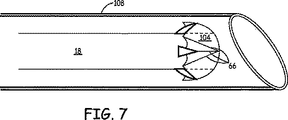
図7を参照すると、本教示の実施形態でのペーシングリードの送出のための心臓壁貫通システムが示されている。中隔100又は心臓壁102の貫通は複数の方法で行うことができる。しかしながら本開示の目的のために貫通をカテーテルに関連させて説明する。堅い湾曲した案内カテーテル108が右心室106の中に又は心室壁102の近くに配置されることができる。カテーテル104によって、力が心室中隔100又は心室壁102を貫通するために加えられることができる。上述のように、しかしながら中隔100又は心臓壁102の貫通は、鋭い鉄線を進ませ穴を作成し、次いで鉄線を引き抜きこの穴を通って鋭い先端を有するペーシングリードを差し込むことによって、又は心臓壁を貫通するのに十分な堅さのリードにするペーシングリードの中に探り針を配置することによってなどの複数の方法で行うことができる。
Referring to FIG. 7, a cardiac wall penetration system for delivery of a pacing lead in an embodiment of the present teachings is shown. The
AVブロック又は洞不全症候群の場合、右心室のペーシングが正常な心室活性化を維持する。それら患者では、心臓機能がよりよく維持され、心臓の再造形は避けられるか又は縮小されることができる。更に、右心室のペーシング部位が左脚ブロック(LBBB)の場合ブロックの遠位であり得るので、右心室ペーシングはまた、冠状静脈アプローチの代わりに心不全LBBBペーシングで再同期療法のために用いることができる。 In the case of AV block or sinus failure syndrome, right ventricular pacing maintains normal ventricular activation. In those patients, cardiac function is better maintained and cardiac remodeling can be avoided or reduced. In addition, right ventricular pacing can also be used for resynchronization therapy in heart failure LBBB pacing instead of coronary vein approach, as the right ventricular pacing site can be distal to the block when it is a left leg block (LBBB). it can.
図8を参照すると、本教示の実施形態でのペーシングリードの側面が示されている。上述のように、リード18は、リード本体21と、導体54と、電極66と、閉塞ファブリック104とを有する。図9では、電極66は中央部72及び脚74を有する上反り(cambered)のファブリック支持体70を形成し、このファブリック支持体70は上反り式で中央部72から外に延びる。この上反りの形により閉塞ファブリック104が折畳み式蓋の形をとることができ、これによりカテーテル108によって作成された心臓壁の中の穿刺(puncture)を閉塞することを助長する。
Referring to FIG. 8, a side view of a pacing lead in an embodiment of the present teachings is shown. As described above, the
電極66は、柔軟性のある、強い、導電性のMP35Nなどの材料であれば有用である。これにより、脚74がカテーテル108の内側にあると本体21に対して押し込まれ、カテーテル108から抜け出るとその上反りの形に広がり、以下でより詳細に説明するように電極66が左心室壁の方に引き戻されると更に外側に広がることが可能になる。図9は、電極66が単極を有する単極構成を示す。図10は、電極67、68が反対の極性又はその2つのうち一方が電気的活性化を感知するために用いられる2極リード構成を示す。電極67、68はまた中央部76及び脚78を有する上反りのファブリック支持体70を形成する。
The
図11を参照すると、本教示の実施形態でのペーシングリードの側面図が示されている。図12では、電極80が中央部84及び脚86を有する上反りのファブリック支持体82を形成し、このファブリック支持体82は上反りの方法で中央部84から外側に延びる。この実施形態では、閉塞ファブリック104は小葉(leaflet)の形を有する。図12は電極80が単極を有する単極構成を示す。図13は、電極88、90が反対の極性又はその2つのうち一方が電気的活動を感知するために用いられる2極リード構成を示す。電極88、90はまた中央部92及び脚94を有する上反りのファブリック支持体82を形成する。
Referring to FIG. 11, a side view of a pacing lead in an embodiment of the present teachings is shown. In FIG. 12, the
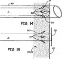
図14から16を参照すると、本教示の実施形態での挿入及び植込みならびにペーシングの方法の間のペーシングリードが示されている。上述のように、挿入の間カテーテル108は、心室壁100又は102を通って穴200を作成するために用いられる(ステップ300)。臨床医学者は、カテーテル108が左心室107に到達すると(ステップ 302)、カテーテル108を通って左心室107の中にリード18を押し入れ(ステップ 304)、カテーテル108を取り外すこととなる。次いで、上反りの支持体構造70は折畳み式蓋の形で広がる。次いで、リード18は、穴200を密閉するために上反りの支持体構造70が図15に示すように更に広がるように引き込められることができる(ステップ 306)。
Referring to FIGS. 14-16, pacing leads during insertion and implantation and pacing methods in embodiments of the present teachings are shown. As described above, during insertion, the
この引込み作用によりまた、電極66又は電極67、68が心室壁100又は102の内部210に対して押し付けられる。時間とともに瘢痕組織は閉塞ファブリック104の上に成長することになり、したがってファブリック104を穴200の上に保持することを助長する。更に挿入時ファブリック104によって覆われた歯202は、折畳み式蓋が広がるとき急に飛び出し、臨床医学者が内壁100又は102に対して電極66を戻すためにリード18を引き込むことを可能にするが、臨床医学者が電極を心室の中にふたたび押し戻すことを阻止し、このようにしてリード18をしっかりと固定する。歯202は電極として作用するために導体に連結され、したがって2極ペーシングを形成することができることを更に意図するものである。リード18が植え込まれた後、次いでペースメーカー10は、どのような心臓の異常も検出し、必要ならばペーシング療法を実現する(ステップ308)。
This retraction action also forces the
図17及び図18を参照すると、本教示の実施形態での挿入及び植込みの間のペーシングリードが示されている。リード18は、別の固定構造を形成するために鋸歯状の縁部212と共に形成される。電極66又は電極67、68が心室壁100又は心室壁102の内部210に対して押し付けられるカテーテル108の挿入及びリード18の引込みの後、固定リング220/222が、リード18の上を通り鋸歯状の縁部212に滑り落されることができる。次いで、固定リング220/222は、右心室壁230に当接するまで鋸歯状の縁部212の上を滑り落される。固定リング220/222はリード18の遠位端の方へ押されることができる。
Referring to FIGS. 17 and 18, a pacing lead during insertion and implantation in an embodiment of the present teachings is shown. The
しかしながら、鋸歯状の縁部212は、固定リング220/222がリード18の近位端の方へ引き戻されることを阻止する。したがって、固定リング220/222は、鋸歯状の縁部212とあいまってリード18が左心室107の中に押されることを阻止するために固定リング220/222が定位置に係止する点でタイストラップ(tie strap)と同様に作用する。時間とともに瘢痕組織が閉塞ファブリック104の上に成長することとなり、したがって穴200の上にファブリック104を保持することを助長する。更に、固定リング222は、臨床医学者が経心筋植込みアプローチを用いたとき固定リングを心臓12に固定することを可能にするはとめ224を有する。
However, the serrated edge 212 prevents the retaining ring 220/222 from being pulled back toward the proximal end of the
図19を参照すると、本教示の実施形態でペーシングリードを製造する方法の流れ図が示されている。上述のように、リード18は、適したポリエチレン又はシラスチック化合物などの生体適合性材料で作製され電気的に絶縁された外側シース50から形成されたリード本体21を有することができる(ステップ 400)。リード本体21は、リード本体21の中に配置された電気的導体54を体液によってもたらされる腐食効果から保護する。導体54は、機械的及び電気的に電極66に連結される(ステップ 402)。電極66には、閉塞ファブリック104が作動可能に結合される(ステップ 404)。閉塞ファブリック104は、電極66にファブリック104を縫い合わせるなど複数の方法で電極66に取り付けられることができ、又は電極66を受けるポケットを有することができる。
Referring to FIG. 19, a flowchart of a method for manufacturing a pacing lead in an embodiment of the present teachings is shown. As described above, the
図20を参照すると、本教示の実施形態でのペーシングリードが示されている。リード本体500は、シリコンラバー又はポリウレタンなど生体適合性材料から形成される。リード本体500は電極502、504を有することができ、電極502、504はそれぞれ電極506、508に作動可能に結合させることができる。電極506、508は、一般にニチノール又はNiTiとして呼称される近化学量論のニッケル・チタニウム合金など柔軟性のある弾力的に変形可能な材料から形成することができる。この種の超弾力性の材料は、他のほとんどの材料より非常に大きな程度に弾性的に変形し、更に開放されたときそれらの当初の形を実質的に完全に取り戻すことができる。
Referring to FIG. 20, a pacing lead in an embodiment of the present teachings is shown. The
これにより電極506、508が中への挿入及び通路通過のために十分に変形されることが可能になり、また小さな直径のカテーテルは、カテーテルを抜け出ると自動的に弾性的に当初の形に戻る。一片の絶縁体510が電極506、508の間に配置され、電極506、508を電気的に分離するために作用するが、リード501の植込みの間穴200を閉塞するためにも作用する。絶縁体510は、ダルコンなどほとんどどのような絶縁材料からでも作製されることができ、電極506、508のようにカテーテルの内側にあると押し込まれ、更に取付けの間カテーテルから取り外されると完全に開くことができるように比較的弾力的である。
This allows the
このようにして、経中隔/経心筋心室ペーシングリード(Trans-Septal/Trans-myocardial Ventricular Pacing)の実施形態が開示されている。本教示が開示した実施形態以外の実施形態で実施することができることが当分野の技術者には理解されよう。開示した実施形態は例示の目的で示され限定的ではなく、本教示は特許請求の範囲によってのみ限定される。 Thus, an embodiment of a trans-septal / trans-myocardial Ventricular Pacing is disclosed. Those skilled in the art will appreciate that the present teachings may be practiced with embodiments other than those disclosed. The disclosed embodiments are presented for purposes of illustration and not limitation, and the present teachings are limited only by the claims.
Claims (3)
前記近位端から前記遠位端へ通り抜ける導体(54)と、
前記リード本体の前記遠位端に配置され、心臓を電気的に刺激するようになされた前記導体に電気的に結合された電極(66)と、
前記リード本体の前記遠位端に配置され、前記心臓の穿刺を覆うようになされた形で前記電極によって支持された閉塞ファブリック(104)と、を備え、
前記電極が前記閉塞ファブリックのために上反りのファブリック支持体構造(70)を形成し、
前記電極(66)が上反り式で外側に延びる脚(74)を有する中央部(72)を有する医用電気的リード。A lead body (21) having a proximal end and a distal end;
A conductor (54) extending from the proximal end to the distal end;
An electrode (66) disposed at the distal end of the lead body and electrically coupled to the conductor adapted to electrically stimulate the heart;
An occlusion fabric (104) disposed at the distal end of the lead body and supported by the electrode in a manner adapted to cover the puncture of the heart ;
The electrodes form a warped fabric support structure (70) for the occlusive fabric;
A medical electrical lead having a central portion (72) wherein said electrode (66) has an upwardly extending leg (74) .
Applications Claiming Priority (3)
| Application Number | Priority Date | Filing Date | Title |
|---|---|---|---|
| US11/096,510 US7321798B2 (en) | 2005-03-31 | 2005-03-31 | Trans-septal/trans-myocardial ventricular pacing lead |
| US11/096,510 | 2005-03-31 | ||
| PCT/US2006/011899 WO2006105395A2 (en) | 2005-03-31 | 2006-03-30 | Trans-septal/trans-myocardial ventricular pacing lead |
Publications (3)
| Publication Number | Publication Date |
|---|---|
| JP2008534158A JP2008534158A (en) | 2008-08-28 |
| JP2008534158A5 JP2008534158A5 (en) | 2009-03-26 |
| JP4850899B2 true JP4850899B2 (en) | 2012-01-11 |
Family
ID=36950049
Family Applications (1)
| Application Number | Title | Priority Date | Filing Date |
|---|---|---|---|
| JP2008504419A Expired - Fee Related JP4850899B2 (en) | 2005-03-31 | 2006-03-30 | Transseptal / transmyocardial ventricular pacing lead |
Country Status (7)
| Country | Link |
|---|---|
| US (1) | US7321798B2 (en) |
| EP (1) | EP1885435B1 (en) |
| JP (1) | JP4850899B2 (en) |
| AT (1) | ATE507870T1 (en) |
| CA (1) | CA2600413A1 (en) |
| DE (1) | DE602006021737D1 (en) |
| WO (1) | WO2006105395A2 (en) |
Families Citing this family (90)
| Publication number | Priority date | Publication date | Assignee | Title |
|---|---|---|---|---|
| US8290586B2 (en) * | 2004-12-20 | 2012-10-16 | Cardiac Pacemakers, Inc. | Methods, devices and systems for single-chamber pacing using a dual-chamber pacing device |
| US8014861B2 (en) * | 2004-12-20 | 2011-09-06 | Cardiac Pacemakers, Inc. | Systems, devices and methods relating to endocardial pacing for resynchronization |
| US8005544B2 (en) | 2004-12-20 | 2011-08-23 | Cardiac Pacemakers, Inc. | Endocardial pacing devices and methods useful for resynchronization and defibrillation |
| US8326423B2 (en) | 2004-12-20 | 2012-12-04 | Cardiac Pacemakers, Inc. | Devices and methods for steering electrical stimulation in cardiac rhythm management |
| US8050756B2 (en) | 2004-12-20 | 2011-11-01 | Cardiac Pacemakers, Inc. | Circuit-based devices and methods for pulse control of endocardial pacing in cardiac rhythm management |
| US8423139B2 (en) | 2004-12-20 | 2013-04-16 | Cardiac Pacemakers, Inc. | Methods, devices and systems for cardiac rhythm management using an electrode arrangement |
| US8010192B2 (en) | 2004-12-20 | 2011-08-30 | Cardiac Pacemakers, Inc. | Endocardial pacing relating to conduction abnormalities |
| AR047851A1 (en) | 2004-12-20 | 2006-03-01 | Giniger Alberto German | A NEW MARCAPASOS THAT RESTORES OR PRESERVES THE PHYSIOLOGICAL ELECTRIC DRIVING OF THE HEART AND A METHOD OF APPLICATION |
| US8010191B2 (en) * | 2004-12-20 | 2011-08-30 | Cardiac Pacemakers, Inc. | Systems, devices and methods for monitoring efficiency of pacing |
| US7899550B1 (en) * | 2006-08-21 | 2011-03-01 | Pacesetter, Inc. | Apparatus and method for transseptal fixation |
| US20080294229A1 (en) * | 2006-10-17 | 2008-11-27 | Friedman Paul A | Helical Electrodes for Intramyocardial Pacing and Sensing |
| WO2008058265A2 (en) * | 2006-11-08 | 2008-05-15 | Emerge Medsystems Llc | Transmuscular left ventricular cardiac stimulation leads and related systems and methods |
| WO2009006325A1 (en) * | 2007-06-29 | 2009-01-08 | Action Medical, Inc. | Devices and methods for steering electrical stimulation in cardiac rhythm management |
| DE102008040304A1 (en) * | 2008-07-10 | 2010-01-14 | Biotronik Crm Patent Ag | Implantable electrode lead or electrode lead assembly |
| EP3536376A1 (en) | 2008-07-30 | 2019-09-11 | Ecole Polytechnique Fédérale de Lausanne | Apparatus for optimized stimulation of a neurological target |
| US9750592B2 (en) * | 2008-10-10 | 2017-09-05 | Carsten Nils Gutt | Arrangement for implanting and method for implanting |
| JP5667987B2 (en) | 2008-11-12 | 2015-02-12 | エコーレ ポリテクニーク フェデラーレ デ ローザンヌ (イーピーエフエル) | Micromachined nerve stimulation device |
| EP2384222A2 (en) | 2008-12-19 | 2011-11-09 | Cardiac Pacemakers, Inc. | Devices, methods, and systems including cardiac pacing |
| DE102009030340B4 (en) * | 2009-06-25 | 2011-12-01 | Peter Osypka | Electrode arrangement with a stimulation electrode for the left ventricle |
| US8406896B2 (en) * | 2009-06-29 | 2013-03-26 | Boston Scientific Neuromodulation Corporation | Multi-element contact assemblies for electrical stimulation systems and systems and methods of making and using |
| EP2453807A4 (en) * | 2009-07-17 | 2017-06-21 | Richard B. North | Shaped electrode and dissecting tool |
| WO2011028949A1 (en) | 2009-09-03 | 2011-03-10 | Mayo Foundation For Medical Education And Research | Pacing, sensing or defibrillator leads for implantation into the myocardium |
| JP2013512062A (en) | 2009-12-01 | 2013-04-11 | エコーレ ポリテクニーク フェデラーレ デ ローザンヌ | Microfabricated surface nerve stimulation device and methods of making and using the same |
| US9549708B2 (en) | 2010-04-01 | 2017-01-24 | Ecole Polytechnique Federale De Lausanne | Device for interacting with neurological tissue and methods of making and using the same |
| WO2011139691A1 (en) | 2010-04-27 | 2011-11-10 | Cardiac Pacemakers, Inc. | His-bundle capture verification and monitoring |
| US9072872B2 (en) | 2010-10-29 | 2015-07-07 | Medtronic, Inc. | Telescoping catheter delivery system for left heart endocardial device placement |
| US8942829B2 (en) | 2011-01-20 | 2015-01-27 | Medtronic, Inc. | Trans-septal lead anchoring |
| EP3476430B1 (en) | 2014-05-16 | 2020-07-01 | Aleva Neurotherapeutics SA | Device for interacting with neurological tissue |
| US11311718B2 (en) | 2014-05-16 | 2022-04-26 | Aleva Neurotherapeutics Sa | Device for interacting with neurological tissue and methods of making and using the same |
| US9403011B2 (en) | 2014-08-27 | 2016-08-02 | Aleva Neurotherapeutics | Leadless neurostimulator |
| US9474894B2 (en) | 2014-08-27 | 2016-10-25 | Aleva Neurotherapeutics | Deep brain stimulation lead |
| US10905886B2 (en) | 2015-12-28 | 2021-02-02 | Cardiac Pacemakers, Inc. | Implantable medical device for deployment across the atrioventricular septum |
| CN109069824B (en) | 2016-02-02 | 2022-09-16 | 阿莱瓦神经治疗股份有限公司 | Treatment of autoimmune diseases using deep brain stimulation |
| US10668294B2 (en) | 2016-05-10 | 2020-06-02 | Cardiac Pacemakers, Inc. | Leadless cardiac pacemaker configured for over the wire delivery |
| WO2018009569A1 (en) | 2016-07-06 | 2018-01-11 | Cardiac Pacemakers, Inc. | Method and system for determining an atrial contraction timing fiducial in a leadless cardiac pacemaker system |
| WO2018017226A1 (en) | 2016-07-20 | 2018-01-25 | Cardiac Pacemakers, Inc. | System for utilizing an atrial contraction timing fiducial in a leadless cardiac pacemaker system |
| WO2018035343A1 (en) | 2016-08-19 | 2018-02-22 | Cardiac Pacemakers, Inc. | Trans septal implantable medical device |
| US10905889B2 (en) | 2016-09-21 | 2021-02-02 | Cardiac Pacemakers, Inc. | Leadless stimulation device with a housing that houses internal components of the leadless stimulation device and functions as the battery case and a terminal of an internal battery |
| US10758737B2 (en) | 2016-09-21 | 2020-09-01 | Cardiac Pacemakers, Inc. | Using sensor data from an intracardially implanted medical device to influence operation of an extracardially implantable cardioverter |
| WO2018057626A1 (en) | 2016-09-21 | 2018-03-29 | Cardiac Pacemakers, Inc. | Implantable cardiac monitor |
| WO2018081237A1 (en) | 2016-10-27 | 2018-05-03 | Cardiac Pacemakers, Inc. | Use of a separate device in managing the pace pulse energy of a cardiac pacemaker |
| EP3532159B1 (en) | 2016-10-27 | 2021-12-22 | Cardiac Pacemakers, Inc. | Implantable medical device delivery system with integrated sensor |
| US10561330B2 (en) | 2016-10-27 | 2020-02-18 | Cardiac Pacemakers, Inc. | Implantable medical device having a sense channel with performance adjustment |
| US10765871B2 (en) | 2016-10-27 | 2020-09-08 | Cardiac Pacemakers, Inc. | Implantable medical device with pressure sensor |
| US10413733B2 (en) | 2016-10-27 | 2019-09-17 | Cardiac Pacemakers, Inc. | Implantable medical device with gyroscope |
| JP6843235B2 (en) | 2016-10-31 | 2021-03-17 | カーディアック ペースメイカーズ, インコーポレイテッド | Systems and methods for activity level pacing |
| CN109890456B (en) | 2016-10-31 | 2023-06-13 | 心脏起搏器股份公司 | System for activity level pacing |
| WO2018089311A1 (en) | 2016-11-08 | 2018-05-17 | Cardiac Pacemakers, Inc | Implantable medical device for atrial deployment |
| US10632313B2 (en) | 2016-11-09 | 2020-04-28 | Cardiac Pacemakers, Inc. | Systems, devices, and methods for setting cardiac pacing pulse parameters for a cardiac pacing device |
| US10806931B2 (en) | 2016-12-27 | 2020-10-20 | Cardiac Pacemakers, Inc. | Delivery devices and methods for leadless cardiac devices |
| EP3562547B1 (en) | 2016-12-27 | 2020-11-18 | Cardiac Pacemakers, Inc. | Leadless delivery catheter with conductive pathway |
| US10894162B2 (en) | 2016-12-27 | 2021-01-19 | Cardiac Pacemakers, Inc. | Delivery devices and methods for leadless cardiac devices |
| US10485981B2 (en) | 2016-12-27 | 2019-11-26 | Cardiac Pacemakers, Inc. | Fixation methods for leadless cardiac devices |
| CN110225779B (en) | 2017-01-26 | 2023-04-04 | 心脏起搏器股份公司 | Delivery device for leadless cardiac devices |
| JP7000438B2 (en) | 2017-01-26 | 2022-01-19 | カーディアック ペースメイカーズ, インコーポレイテッド | Human device communication with redundant message transmission |
| EP3573708B1 (en) | 2017-01-26 | 2021-03-10 | Cardiac Pacemakers, Inc. | Leadless implantable device with detachable fixation |
| US11229798B2 (en) | 2017-03-10 | 2022-01-25 | Cardiac Pacemakers, Inc. | Fixation for leadless cardiac devices |
| US10737092B2 (en) | 2017-03-30 | 2020-08-11 | Cardiac Pacemakers, Inc. | Delivery devices and methods for leadless cardiac devices |
| AU2018248361B2 (en) | 2017-04-03 | 2020-08-27 | Cardiac Pacemakers, Inc. | Cardiac pacemaker with pacing pulse energy adjustment based on sensed heart rate |
| US10905872B2 (en) | 2017-04-03 | 2021-02-02 | Cardiac Pacemakers, Inc. | Implantable medical device with a movable electrode biased toward an extended position |
| US11577085B2 (en) | 2017-08-03 | 2023-02-14 | Cardiac Pacemakers, Inc. | Delivery devices and methods for leadless cardiac devices |
| US11065459B2 (en) | 2017-08-18 | 2021-07-20 | Cardiac Pacemakers, Inc. | Implantable medical device with pressure sensor |
| US10918875B2 (en) | 2017-08-18 | 2021-02-16 | Cardiac Pacemakers, Inc. | Implantable medical device with a flux concentrator and a receiving coil disposed about the flux concentrator |
| CN111107899B (en) | 2017-09-20 | 2024-04-02 | 心脏起搏器股份公司 | Implantable medical device with multiple modes of operation |
| US11185703B2 (en) | 2017-11-07 | 2021-11-30 | Cardiac Pacemakers, Inc. | Leadless cardiac pacemaker for bundle of his pacing |
| WO2019108482A1 (en) | 2017-12-01 | 2019-06-06 | Cardiac Pacemakers, Inc. | Methods and systems for detecting atrial contraction timing fiducials and determining a cardiac interval from a ventricularly implanted leadless cardiac pacemaker |
| CN111417433A (en) | 2017-12-01 | 2020-07-14 | 心脏起搏器股份公司 | Method and system for detecting atrial contraction timing reference during ventricular filling from a ventricular implanted leadless cardiac pacemaker |
| EP3717059A1 (en) | 2017-12-01 | 2020-10-07 | Cardiac Pacemakers, Inc. | Methods and systems for detecting atrial contraction timing fiducials within a search window from a ventricularly implanted leadless cardiac pacemaker |
| WO2019108830A1 (en) | 2017-12-01 | 2019-06-06 | Cardiac Pacemakers, Inc. | Leadless cardiac pacemaker with reversionary behavior |
| US10874861B2 (en) | 2018-01-04 | 2020-12-29 | Cardiac Pacemakers, Inc. | Dual chamber pacing without beat-to-beat communication |
| US11529523B2 (en) | 2018-01-04 | 2022-12-20 | Cardiac Pacemakers, Inc. | Handheld bridge device for providing a communication bridge between an implanted medical device and a smartphone |
| US10702692B2 (en) | 2018-03-02 | 2020-07-07 | Aleva Neurotherapeutics | Neurostimulation device |
| CN111902187A (en) | 2018-03-23 | 2020-11-06 | 美敦力公司 | VFA cardiac resynchronization therapy |
| CN111886046A (en) | 2018-03-23 | 2020-11-03 | 美敦力公司 | AV-synchronized VFA cardiac therapy |
| US11058880B2 (en) | 2018-03-23 | 2021-07-13 | Medtronic, Inc. | VFA cardiac therapy for tachycardia |
| CN112770807A (en) | 2018-09-26 | 2021-05-07 | 美敦力公司 | Capture in atrial-to-ventricular cardiac therapy |
| US11679265B2 (en) | 2019-02-14 | 2023-06-20 | Medtronic, Inc. | Lead-in-lead systems and methods for cardiac therapy |
| US11446510B2 (en) | 2019-03-29 | 2022-09-20 | Cardiac Pacemakers, Inc. | Systems and methods for treating cardiac arrhythmias |
| US11697025B2 (en) | 2019-03-29 | 2023-07-11 | Medtronic, Inc. | Cardiac conduction system capture |
| US11833349B2 (en) | 2019-03-29 | 2023-12-05 | Cardiac Pacemakers, Inc. | Systems and methods for treating cardiac arrhythmias |
| US11213676B2 (en) | 2019-04-01 | 2022-01-04 | Medtronic, Inc. | Delivery systems for VfA cardiac therapy |
| US11712188B2 (en) | 2019-05-07 | 2023-08-01 | Medtronic, Inc. | Posterior left bundle branch engagement |
| US11633607B2 (en) | 2019-07-24 | 2023-04-25 | Medtronic, Inc. | AV synchronous septal pacing |
| US11305127B2 (en) | 2019-08-26 | 2022-04-19 | Medtronic Inc. | VfA delivery and implant region detection |
| CN114364431A (en) | 2019-09-11 | 2022-04-15 | 心脏起搏器股份公司 | Tool and system for implanting and/or retrieving a leadless cardiac pacing device having a helical fixation member |
| WO2021050685A1 (en) | 2019-09-11 | 2021-03-18 | Cardiac Pacemakers, Inc. | Tools and systems for implanting and/or retrieving a leadless cardiac pacing device with helix fixation |
| US11813466B2 (en) | 2020-01-27 | 2023-11-14 | Medtronic, Inc. | Atrioventricular nodal stimulation |
| US20210275824A1 (en) * | 2020-03-06 | 2021-09-09 | Medtronic, Inc. | Multi-electrode implantable medical device (imd) |
| US11911168B2 (en) | 2020-04-03 | 2024-02-27 | Medtronic, Inc. | Cardiac conduction system therapy benefit determination |
| US11813464B2 (en) | 2020-07-31 | 2023-11-14 | Medtronic, Inc. | Cardiac conduction system evaluation |
Citations (6)
| Publication number | Priority date | Publication date | Assignee | Title |
|---|---|---|---|---|
| JPH0716299A (en) * | 1992-10-22 | 1995-01-20 | Medtronic Inc | Cardiac muscle pacing lead |
| US20030199962A1 (en) * | 2002-04-22 | 2003-10-23 | Chester Struble | Anti-slip leads for placement within tissue |
| WO2004028348A2 (en) * | 2002-09-26 | 2004-04-08 | Savacor, Inc. | Cardiovascular anchoring device and method of deploying same |
| JP2004532700A (en) * | 2001-05-01 | 2004-10-28 | イントラペース インコーポレイテッド | Gastric treatment diagnosis apparatus and method |
| US20040230283A1 (en) * | 2001-11-29 | 2004-11-18 | Medtronic, Inc. | Trans-septal pacing method and apparatus |
| US20050065589A1 (en) * | 2003-07-25 | 2005-03-24 | Schneider Richard Lee | Method and anchor for medical implant placement, and method of anchor manufacture |
Family Cites Families (37)
| Publication number | Priority date | Publication date | Assignee | Title |
|---|---|---|---|---|
| US4946457A (en) * | 1987-12-03 | 1990-08-07 | Dimed, Incorporated | Defibrillator system with cardiac leads and method for transvenous implantation |
| US5158078A (en) | 1990-08-14 | 1992-10-27 | Medtronic, Inc. | Rate responsive pacemaker and methods for optimizing its operation |
| US5144949A (en) | 1991-03-15 | 1992-09-08 | Medtronic, Inc. | Dual chamber rate responsive pacemaker with automatic mode switching |
| DE69229539T2 (en) | 1991-11-05 | 2000-02-17 | Childrens Medical Center | Occlusion device for repairing heart and vascular defects |
| US5312453A (en) | 1992-05-11 | 1994-05-17 | Medtronic, Inc. | Rate responsive cardiac pacemaker and method for work-modulating pacing rate deceleration |
| US5336252A (en) | 1992-06-22 | 1994-08-09 | Cohen Donald M | System and method for implanting cardiac electrical leads |
| US5293869A (en) * | 1992-09-25 | 1994-03-15 | Ep Technologies, Inc. | Cardiac probe with dynamic support for maintaining constant surface contact during heart systole and diastole |
| WO1997016119A1 (en) | 1995-10-30 | 1997-05-09 | Children's Medical Center Corporation | Self-centering umbrella-type septal closure device |
| US5662698A (en) * | 1995-12-06 | 1997-09-02 | Ventritex, Inc. | Nonshunting endocardial defibrillation lead |
| US5728140A (en) | 1996-06-17 | 1998-03-17 | Cardiac Pacemakers, Inc. | Method for evoking capture of left ventricle using transeptal pacing lead |
| US5741297A (en) * | 1996-08-28 | 1998-04-21 | Simon; Morris | Daisy occluder and method for septal defect repair |
| US6048553A (en) | 1997-03-17 | 2000-04-11 | Macquarie Veterinary Supplies Pty Ltd | Aqueous metal bicarbonate solution useful in treating inflammatory, degenerative and viral diseases |
| US20010044619A1 (en) | 1998-04-08 | 2001-11-22 | Peter A. Altman | Cardiac drug delivery system and method for use |
| US6245012B1 (en) | 1999-03-19 | 2001-06-12 | Nmt Medical, Inc. | Free standing filter |
| US6551344B2 (en) * | 2000-04-26 | 2003-04-22 | Ev3 Inc. | Septal defect occluder |
| US6440152B1 (en) | 2000-07-28 | 2002-08-27 | Microvena Corporation | Defect occluder release assembly and method |
| US6746404B2 (en) | 2000-12-18 | 2004-06-08 | Biosense, Inc. | Method for anchoring a medical device between tissue |
| AU2002323634A1 (en) | 2001-09-06 | 2003-03-24 | Nmt Medical, Inc. | Flexible delivery system |
| US7318833B2 (en) | 2001-12-19 | 2008-01-15 | Nmt Medical, Inc. | PFO closure device with flexible thrombogenic joint and improved dislodgement resistance |
| WO2003059152A2 (en) | 2002-01-14 | 2003-07-24 | Nmt Medical, Inc. | Patent foramen ovale (pfo) closure method and device |
| US20030139819A1 (en) | 2002-01-18 | 2003-07-24 | Beer Nicholas De | Method and apparatus for closing septal defects |
| CA2643221A1 (en) | 2002-03-15 | 2003-09-25 | Nmt Medical, Inc. | Coupling system useful in placement of implants |
| JP2005521447A (en) | 2002-03-25 | 2005-07-21 | エヌエムティー メディカル インコーポレイテッド | Closure clip of patent foramen ovale (PFO) |
| US7177704B2 (en) | 2002-04-29 | 2007-02-13 | Medtronic, Inc. | Pacing method and apparatus |
| US7840261B2 (en) | 2002-06-05 | 2010-11-23 | Biocardia, Inc. | Catheter systems and methods for placing bi-ventricular pacing leads |
| WO2003103476A2 (en) | 2002-06-05 | 2003-12-18 | Nmt Medical, Inc. | Patent foramen ovale (pfo) closure device with radial and circumferential support |
| ES2298556T3 (en) | 2002-09-23 | 2008-05-16 | Nmt Medical, Inc. | SEPTAL PUNCTURE DEVICE. |
| US7082335B2 (en) | 2002-09-30 | 2006-07-25 | Medtronic, Inc. | Multipolar pacing method and apparatus |
| US20040127855A1 (en) | 2002-10-10 | 2004-07-01 | Nmt Medical, Inc. | Hemostasis valve |
| AU2003284976A1 (en) | 2002-10-25 | 2004-05-13 | Nmt Medical, Inc. | Expandable sheath tubing |
| AU2003287554A1 (en) | 2002-11-06 | 2004-06-03 | Nmt Medical, Inc. | Medical devices utilizing modified shape memory alloy |
| DE60325880D1 (en) | 2002-11-07 | 2009-03-05 | Nmt Medical Inc | AGNETIC POWER |
| EP2399526B1 (en) | 2002-12-09 | 2014-11-26 | W.L. Gore & Associates, Inc. | Septal closure devices |
| US7618435B2 (en) | 2003-03-04 | 2009-11-17 | Nmt Medical, Inc. | Magnetic attachment systems |
| US20040176788A1 (en) | 2003-03-07 | 2004-09-09 | Nmt Medical, Inc. | Vacuum attachment system |
| FR2859912B1 (en) | 2003-09-22 | 2005-11-18 | Ela Medical Sa | NECESSARY FOR DRILLING THE CARDIAC SEPTUM AND PLACING A TRANSSEPTAL DEVICE, IN PARTICULAR A STIMULATION PROBE OF A LEFT CAVITY |
| US7212869B2 (en) * | 2004-02-04 | 2007-05-01 | Medtronic, Inc. | Lead retention means |
-
2005
- 2005-03-31 US US11/096,510 patent/US7321798B2/en not_active Expired - Fee Related
-
2006
- 2006-03-30 CA CA002600413A patent/CA2600413A1/en not_active Abandoned
- 2006-03-30 JP JP2008504419A patent/JP4850899B2/en not_active Expired - Fee Related
- 2006-03-30 DE DE602006021737T patent/DE602006021737D1/en active Active
- 2006-03-30 AT AT06740193T patent/ATE507870T1/en not_active IP Right Cessation
- 2006-03-30 WO PCT/US2006/011899 patent/WO2006105395A2/en active Application Filing
- 2006-03-30 EP EP06740193A patent/EP1885435B1/en not_active Not-in-force
Patent Citations (6)
| Publication number | Priority date | Publication date | Assignee | Title |
|---|---|---|---|---|
| JPH0716299A (en) * | 1992-10-22 | 1995-01-20 | Medtronic Inc | Cardiac muscle pacing lead |
| JP2004532700A (en) * | 2001-05-01 | 2004-10-28 | イントラペース インコーポレイテッド | Gastric treatment diagnosis apparatus and method |
| US20040230283A1 (en) * | 2001-11-29 | 2004-11-18 | Medtronic, Inc. | Trans-septal pacing method and apparatus |
| US20030199962A1 (en) * | 2002-04-22 | 2003-10-23 | Chester Struble | Anti-slip leads for placement within tissue |
| WO2004028348A2 (en) * | 2002-09-26 | 2004-04-08 | Savacor, Inc. | Cardiovascular anchoring device and method of deploying same |
| US20050065589A1 (en) * | 2003-07-25 | 2005-03-24 | Schneider Richard Lee | Method and anchor for medical implant placement, and method of anchor manufacture |
Also Published As
| Publication number | Publication date |
|---|---|
| US20060224224A1 (en) | 2006-10-05 |
| EP1885435A2 (en) | 2008-02-13 |
| EP1885435B1 (en) | 2011-05-04 |
| US7321798B2 (en) | 2008-01-22 |
| WO2006105395A2 (en) | 2006-10-05 |
| WO2006105395A3 (en) | 2006-11-30 |
| DE602006021737D1 (en) | 2011-06-16 |
| ATE507870T1 (en) | 2011-05-15 |
| CA2600413A1 (en) | 2006-10-05 |
| JP2008534158A (en) | 2008-08-28 |
Similar Documents
| Publication | Publication Date | Title |
|---|---|---|
| JP4850899B2 (en) | Transseptal / transmyocardial ventricular pacing lead | |
| US7177704B2 (en) | Pacing method and apparatus | |
| US9610438B2 (en) | Delivery catheter including side port and electrodes | |
| US5643338A (en) | Single-pass A-V lead for pacing with stimulation of right ventricular outflow tract | |
| US9561106B2 (en) | Cardiac access methods and apparatus | |
| US7418298B2 (en) | Myocardial lead with fixation mechanism | |
| US5693081A (en) | Endocardial lead system with defibrillation electrode fixation | |
| US6937897B2 (en) | Electrode for His bundle stimulation | |
| US3865118A (en) | Transvenous coaxial catheter | |
| US4858623A (en) | Active fixation mechanism for lead assembly of an implantable cardiac stimulator | |
| US8315716B2 (en) | Sheath and electrical lead | |
| US9265937B2 (en) | Implantable indifferent reference electrode pole | |
| US8942829B2 (en) | Trans-septal lead anchoring | |
| US20080051864A1 (en) | Epicardial lead | |
| US7499759B2 (en) | Distal or proximal fixation of over-the-tether myocardial leads | |
| WO2005107860A2 (en) | Papillary muscle stimulation | |
| JPH02307481A (en) | Positive fixing mechanism for lead assembly of buried cardiotonic device | |
| US20240009453A1 (en) | Cardiac pacing leads and delivery system |
Legal Events
| Date | Code | Title | Description |
|---|---|---|---|
| A521 | Request for written amendment filed |
Free format text: JAPANESE INTERMEDIATE CODE: A523 Effective date: 20090129 |
|
| A621 | Written request for application examination |
Free format text: JAPANESE INTERMEDIATE CODE: A621 Effective date: 20090129 |
|
| RD04 | Notification of resignation of power of attorney |
Free format text: JAPANESE INTERMEDIATE CODE: A7424 Effective date: 20110905 |
|
| TRDD | Decision of grant or rejection written | ||
| A01 | Written decision to grant a patent or to grant a registration (utility model) |
Free format text: JAPANESE INTERMEDIATE CODE: A01 Effective date: 20110921 |
|
| A01 | Written decision to grant a patent or to grant a registration (utility model) |
Free format text: JAPANESE INTERMEDIATE CODE: A01 |
|
| A61 | First payment of annual fees (during grant procedure) |
Free format text: JAPANESE INTERMEDIATE CODE: A61 Effective date: 20111019 |
|
| R150 | Certificate of patent or registration of utility model |
Free format text: JAPANESE INTERMEDIATE CODE: R150 |
|
| FPAY | Renewal fee payment (event date is renewal date of database) |
Free format text: PAYMENT UNTIL: 20141028 Year of fee payment: 3 |
|
| R250 | Receipt of annual fees |
Free format text: JAPANESE INTERMEDIATE CODE: R250 |
|
| R250 | Receipt of annual fees |
Free format text: JAPANESE INTERMEDIATE CODE: R250 |
|
| R250 | Receipt of annual fees |
Free format text: JAPANESE INTERMEDIATE CODE: R250 |
|
| LAPS | Cancellation because of no payment of annual fees |