JP4841633B2 - Prosthesis with mechanically actuable finger - Google Patents
Prosthesis with mechanically actuable finger Download PDFInfo
- Publication number
- JP4841633B2 JP4841633B2 JP2008542815A JP2008542815A JP4841633B2 JP 4841633 B2 JP4841633 B2 JP 4841633B2 JP 2008542815 A JP2008542815 A JP 2008542815A JP 2008542815 A JP2008542815 A JP 2008542815A JP 4841633 B2 JP4841633 B2 JP 4841633B2
- Authority
- JP
- Japan
- Prior art keywords
- worm
- drive motor
- prosthesis
- worm gear
- finger member
- Prior art date
- Legal status (The legal status is an assumption and is not a legal conclusion. Google has not performed a legal analysis and makes no representation as to the accuracy of the status listed.)
- Expired - Fee Related
Links
Images


Classifications
-
- A—HUMAN NECESSITIES
- A61—MEDICAL OR VETERINARY SCIENCE; HYGIENE
- A61F—FILTERS IMPLANTABLE INTO BLOOD VESSELS; PROSTHESES; DEVICES PROVIDING PATENCY TO, OR PREVENTING COLLAPSING OF, TUBULAR STRUCTURES OF THE BODY, e.g. STENTS; ORTHOPAEDIC, NURSING OR CONTRACEPTIVE DEVICES; FOMENTATION; TREATMENT OR PROTECTION OF EYES OR EARS; BANDAGES, DRESSINGS OR ABSORBENT PADS; FIRST-AID KITS
- A61F2/00—Filters implantable into blood vessels; Prostheses, i.e. artificial substitutes or replacements for parts of the body; Appliances for connecting them with the body; Devices providing patency to, or preventing collapsing of, tubular structures of the body, e.g. stents
- A61F2/50—Prostheses not implantable in the body
- A61F2/54—Artificial arms or hands or parts thereof
- A61F2/58—Elbows; Wrists ; Other joints; Hands
- A61F2/583—Hands; Wrist joints
- A61F2/586—Fingers
-
- A—HUMAN NECESSITIES
- A61—MEDICAL OR VETERINARY SCIENCE; HYGIENE
- A61F—FILTERS IMPLANTABLE INTO BLOOD VESSELS; PROSTHESES; DEVICES PROVIDING PATENCY TO, OR PREVENTING COLLAPSING OF, TUBULAR STRUCTURES OF THE BODY, e.g. STENTS; ORTHOPAEDIC, NURSING OR CONTRACEPTIVE DEVICES; FOMENTATION; TREATMENT OR PROTECTION OF EYES OR EARS; BANDAGES, DRESSINGS OR ABSORBENT PADS; FIRST-AID KITS
- A61F2/00—Filters implantable into blood vessels; Prostheses, i.e. artificial substitutes or replacements for parts of the body; Appliances for connecting them with the body; Devices providing patency to, or preventing collapsing of, tubular structures of the body, e.g. stents
- A61F2/50—Prostheses not implantable in the body
- A61F2/68—Operating or control means
- A61F2/70—Operating or control means electrical
- A61F2/72—Bioelectric control, e.g. myoelectric
-
- A—HUMAN NECESSITIES
- A61—MEDICAL OR VETERINARY SCIENCE; HYGIENE
- A61F—FILTERS IMPLANTABLE INTO BLOOD VESSELS; PROSTHESES; DEVICES PROVIDING PATENCY TO, OR PREVENTING COLLAPSING OF, TUBULAR STRUCTURES OF THE BODY, e.g. STENTS; ORTHOPAEDIC, NURSING OR CONTRACEPTIVE DEVICES; FOMENTATION; TREATMENT OR PROTECTION OF EYES OR EARS; BANDAGES, DRESSINGS OR ABSORBENT PADS; FIRST-AID KITS
- A61F2/00—Filters implantable into blood vessels; Prostheses, i.e. artificial substitutes or replacements for parts of the body; Appliances for connecting them with the body; Devices providing patency to, or preventing collapsing of, tubular structures of the body, e.g. stents
- A61F2/02—Prostheses implantable into the body
- A61F2/30—Joints
- A61F2002/30001—Additional features of subject-matter classified in A61F2/28, A61F2/30 and subgroups thereof
- A61F2002/30316—The prosthesis having different structural features at different locations within the same prosthesis; Connections between prosthetic parts; Special structural features of bone or joint prostheses not otherwise provided for
- A61F2002/30329—Connections or couplings between prosthetic parts, e.g. between modular parts; Connecting elements
- A61F2002/30518—Connections or couplings between prosthetic parts, e.g. between modular parts; Connecting elements with possibility of relative movement between the prosthetic parts
- A61F2002/30523—Connections or couplings between prosthetic parts, e.g. between modular parts; Connecting elements with possibility of relative movement between the prosthetic parts by means of meshing gear teeth
- A61F2002/30525—Worm gears
-
- A—HUMAN NECESSITIES
- A61—MEDICAL OR VETERINARY SCIENCE; HYGIENE
- A61F—FILTERS IMPLANTABLE INTO BLOOD VESSELS; PROSTHESES; DEVICES PROVIDING PATENCY TO, OR PREVENTING COLLAPSING OF, TUBULAR STRUCTURES OF THE BODY, e.g. STENTS; ORTHOPAEDIC, NURSING OR CONTRACEPTIVE DEVICES; FOMENTATION; TREATMENT OR PROTECTION OF EYES OR EARS; BANDAGES, DRESSINGS OR ABSORBENT PADS; FIRST-AID KITS
- A61F2/00—Filters implantable into blood vessels; Prostheses, i.e. artificial substitutes or replacements for parts of the body; Appliances for connecting them with the body; Devices providing patency to, or preventing collapsing of, tubular structures of the body, e.g. stents
- A61F2/50—Prostheses not implantable in the body
- A61F2002/5001—Cosmetic coverings
-
- A—HUMAN NECESSITIES
- A61—MEDICAL OR VETERINARY SCIENCE; HYGIENE
- A61F—FILTERS IMPLANTABLE INTO BLOOD VESSELS; PROSTHESES; DEVICES PROVIDING PATENCY TO, OR PREVENTING COLLAPSING OF, TUBULAR STRUCTURES OF THE BODY, e.g. STENTS; ORTHOPAEDIC, NURSING OR CONTRACEPTIVE DEVICES; FOMENTATION; TREATMENT OR PROTECTION OF EYES OR EARS; BANDAGES, DRESSINGS OR ABSORBENT PADS; FIRST-AID KITS
- A61F2/00—Filters implantable into blood vessels; Prostheses, i.e. artificial substitutes or replacements for parts of the body; Appliances for connecting them with the body; Devices providing patency to, or preventing collapsing of, tubular structures of the body, e.g. stents
- A61F2/50—Prostheses not implantable in the body
- A61F2002/5072—Prostheses not implantable in the body having spring elements
- A61F2002/5073—Helical springs, e.g. having at least one helical spring
-
- A—HUMAN NECESSITIES
- A61—MEDICAL OR VETERINARY SCIENCE; HYGIENE
- A61F—FILTERS IMPLANTABLE INTO BLOOD VESSELS; PROSTHESES; DEVICES PROVIDING PATENCY TO, OR PREVENTING COLLAPSING OF, TUBULAR STRUCTURES OF THE BODY, e.g. STENTS; ORTHOPAEDIC, NURSING OR CONTRACEPTIVE DEVICES; FOMENTATION; TREATMENT OR PROTECTION OF EYES OR EARS; BANDAGES, DRESSINGS OR ABSORBENT PADS; FIRST-AID KITS
- A61F2/00—Filters implantable into blood vessels; Prostheses, i.e. artificial substitutes or replacements for parts of the body; Appliances for connecting them with the body; Devices providing patency to, or preventing collapsing of, tubular structures of the body, e.g. stents
- A61F2/50—Prostheses not implantable in the body
- A61F2002/5081—Additional features
- A61F2002/509—Additional features specially designed for children, e.g. having means for adjusting to their growth
-
- A—HUMAN NECESSITIES
- A61—MEDICAL OR VETERINARY SCIENCE; HYGIENE
- A61F—FILTERS IMPLANTABLE INTO BLOOD VESSELS; PROSTHESES; DEVICES PROVIDING PATENCY TO, OR PREVENTING COLLAPSING OF, TUBULAR STRUCTURES OF THE BODY, e.g. STENTS; ORTHOPAEDIC, NURSING OR CONTRACEPTIVE DEVICES; FOMENTATION; TREATMENT OR PROTECTION OF EYES OR EARS; BANDAGES, DRESSINGS OR ABSORBENT PADS; FIRST-AID KITS
- A61F2/00—Filters implantable into blood vessels; Prostheses, i.e. artificial substitutes or replacements for parts of the body; Appliances for connecting them with the body; Devices providing patency to, or preventing collapsing of, tubular structures of the body, e.g. stents
- A61F2/50—Prostheses not implantable in the body
- A61F2/54—Artificial arms or hands or parts thereof
- A61F2/58—Elbows; Wrists ; Other joints; Hands
- A61F2/583—Hands; Wrist joints
- A61F2/586—Fingers
- A61F2002/587—Thumbs
-
- A—HUMAN NECESSITIES
- A61—MEDICAL OR VETERINARY SCIENCE; HYGIENE
- A61F—FILTERS IMPLANTABLE INTO BLOOD VESSELS; PROSTHESES; DEVICES PROVIDING PATENCY TO, OR PREVENTING COLLAPSING OF, TUBULAR STRUCTURES OF THE BODY, e.g. STENTS; ORTHOPAEDIC, NURSING OR CONTRACEPTIVE DEVICES; FOMENTATION; TREATMENT OR PROTECTION OF EYES OR EARS; BANDAGES, DRESSINGS OR ABSORBENT PADS; FIRST-AID KITS
- A61F2/00—Filters implantable into blood vessels; Prostheses, i.e. artificial substitutes or replacements for parts of the body; Appliances for connecting them with the body; Devices providing patency to, or preventing collapsing of, tubular structures of the body, e.g. stents
- A61F2/50—Prostheses not implantable in the body
- A61F2/68—Operating or control means
- A61F2/70—Operating or control means electrical
- A61F2002/701—Operating or control means electrical operated by electrically controlled means, e.g. solenoids or torque motors
-
- A—HUMAN NECESSITIES
- A61—MEDICAL OR VETERINARY SCIENCE; HYGIENE
- A61F—FILTERS IMPLANTABLE INTO BLOOD VESSELS; PROSTHESES; DEVICES PROVIDING PATENCY TO, OR PREVENTING COLLAPSING OF, TUBULAR STRUCTURES OF THE BODY, e.g. STENTS; ORTHOPAEDIC, NURSING OR CONTRACEPTIVE DEVICES; FOMENTATION; TREATMENT OR PROTECTION OF EYES OR EARS; BANDAGES, DRESSINGS OR ABSORBENT PADS; FIRST-AID KITS
- A61F2/00—Filters implantable into blood vessels; Prostheses, i.e. artificial substitutes or replacements for parts of the body; Appliances for connecting them with the body; Devices providing patency to, or preventing collapsing of, tubular structures of the body, e.g. stents
- A61F2/50—Prostheses not implantable in the body
- A61F2/76—Means for assembling, fitting or testing prostheses, e.g. for measuring or balancing, e.g. alignment means
- A61F2002/7615—Measuring means
- A61F2002/7655—Measuring means for measuring fluid pressure
-
- A—HUMAN NECESSITIES
- A61—MEDICAL OR VETERINARY SCIENCE; HYGIENE
- A61F—FILTERS IMPLANTABLE INTO BLOOD VESSELS; PROSTHESES; DEVICES PROVIDING PATENCY TO, OR PREVENTING COLLAPSING OF, TUBULAR STRUCTURES OF THE BODY, e.g. STENTS; ORTHOPAEDIC, NURSING OR CONTRACEPTIVE DEVICES; FOMENTATION; TREATMENT OR PROTECTION OF EYES OR EARS; BANDAGES, DRESSINGS OR ABSORBENT PADS; FIRST-AID KITS
- A61F2220/00—Fixations or connections for prostheses classified in groups A61F2/00 - A61F2/26 or A61F2/82 or A61F9/00 or A61F11/00 or subgroups thereof
- A61F2220/0025—Connections or couplings between prosthetic parts, e.g. between modular parts; Connecting elements
Abstract
Description
本発明は、少なくとも1つの機械的に作動可能な指部材を有する人工補装具に関する。 The present invention relates to a prosthesis having at least one mechanically actuable finger member.
1つ又は複数の、着用者が作動可能な電気機械的指を提供する手の人工補装具が知られている。従来の人工補装具は、手自体の中に装着された電動モータを使用し、機械的リンク機構を含む伝達システムによって動力を指に伝達することが多い。このような従来の人工補装具は幾つかの欠点を有し、特にモータと伝達システムとの間に精密な位置合わせを必要とするが、これは厄介な配置構成につながることがあり、人工補装具の手の部分に空間的要件を加え、それによって人工補装具は数本の指が残っている患者にとって不適切になることがある。 Hand prostheses are known that provide one or more wearer-operable electromechanical fingers. Conventional prosthetic devices often use an electric motor mounted in the hand itself and often transmit power to the fingers by a transmission system including a mechanical linkage. Such conventional prostheses have several drawbacks, particularly requiring precise alignment between the motor and the transmission system, which can lead to cumbersome arrangements and prosthesis. Adding spatial requirements to the hand portion of the brace, which may make the prosthesis unsuitable for patients with a few remaining fingers.
米国特許第4,623,354号は、手の中にモータが設けられているこのような従来通りの手の人工補装具について説明している。動力は、ウォーム歯車機構を備える伝達システムによってモータの1つから指へと伝達される。
国際公開第95/24875号パンフレットは、従来の人工補装具の上述した欠点に対処する手の人工補装具について説明している。特に、国際公開第95/24875号パンフレットの手の人工補装具は、指部材内に装着された駆動モータ及びギアボックスを備える。駆動モータが作動すると、指部材内に配置されたウォームを駆動する。ウォームは固定されたウォーム歯車と係合して、その周囲で動作し、ウォーム歯車の軸の周囲で指部材を動作させる。
U.S. Pat. No. 4,623,354 describes such a conventional hand prosthesis with a motor in the hand. Power is transmitted from one of the motors to the finger by a transmission system comprising a worm gear mechanism.
WO 95/24875 describes a hand prosthesis that addresses the above-mentioned drawbacks of conventional prostheses. In particular, the hand prosthesis of WO 95/24875 includes a drive motor and a gear box mounted in a finger member. When the drive motor is actuated, the worm arranged in the finger member is driven. The worm engages with a fixed worm gear and moves around it, moving the finger member around the axis of the worm gear.
本発明の発明者は、国際公開第95/24875号パンフレットによる手の人工補装具の特定の欠点を認識している。特に、指部材内の電気機械的構成要素のサイズによって、子供用に適切であるように、短い人工補装具の指に十分な動力のモータ及び適切な比率を有する歯車を設けることが困難になる。 The inventor of the present invention has recognized certain drawbacks of the hand prosthesis according to WO 95/24875. In particular, the size of the electromechanical component in the finger member makes it difficult to provide a motor with sufficient power and a gear with the appropriate ratio on the fingers of a short prosthesis, as appropriate for children. .
したがって、子供用に適切であるような小さい指を提供するように構成された指部材を有する人工補装具を提供することが、本発明の目的である。 Accordingly, it is an object of the present invention to provide a prosthesis having a finger member configured to provide a small finger that is suitable for children.
本発明は、上述した認識に鑑みて考案されており、したがって第一の態様では、少なくとも1つの機械的に作動可能な指部材を提供する人工補装具が提供され、人工補装具は、人工補装具の支持部材上に固定されたウォーム歯車に対して実質的に接線方向に延在する少なくとも1つの前記指部材を有し、指部材は、ウォーム歯車の軸の周囲で回転するように装着され、指部材は、ウォームを駆動するように作動可能な駆動モータを備え、ウォームは、人工補装具の使用時に駆動モータが作動すると、指部材がウォーム歯車の周囲で動作するように、ウォーム歯車と係合するものであり、ウォーム及び駆動モータがウォーム歯車の軸の対向する側に配置されることを特徴とする。
The present invention has been devised in view of the above recognition, and therefore, in a first aspect, an artificial prosthesis is provided that provides at least one mechanically actuable finger member, the artificial prosthesis being an artificial prosthesis. At least one finger member extending substantially tangential to a worm gear secured on a support member of the brace, the finger member being mounted for rotation about an axis of the worm gear The finger member includes a drive motor operable to drive the worm, and the worm includes a worm gear so that the finger member operates around the worm gear when the drive motor is activated when the prosthesis is used. The worm and the drive motor are arranged on opposite sides of the shaft of the worm gear.
したがって、ウォーム手段は指部材の外側に配置される。ウォーム手段を指部材の外側に配置すると、指部材内で電気機械的構成要素が占有する縦方向の空間の量が減少する。これによって、子供用に適切であるような短めの指部材を設計することができる。逆に、国際公開第95/24875号パンフレットの手の人工補装具は、国際公開第95/24875号パンフレットの図2に示すように、指部材内に配置されたウォーム手段(つまりウォーム)を有する。
Therefore, the worm means is disposed outside the finger member. Placing the worm means outside the finger member reduces the amount of vertical space occupied by the electromechanical components within the finger member. This makes it possible to design a shorter finger member that is suitable for children. Conversely, the hand prosthesis of WO 95/24875 has worm means (ie, a worm) disposed within the finger member, as shown in FIG. 2 of WO 95/24875. .
特に、ウォーム手段は指部材に対して横方向に延在してよい。 In particular, the worm means may extend laterally with respect to the finger member.
代替的又は追加的に、ウォーム手段は指部材に対して実質的に直角に延在してよい。 Alternatively or additionally, the worm means may extend substantially perpendicular to the finger member.
このような方法でウォーム手段を配置すると、駆動モータを含む電気機械的構成要素がウォーム歯車手段に向かって動作することができる。 Placing the worm means in this way allows the electromechanical components including the drive motor to move toward the worm gear means.
本発明の形態では、人工補装具はさらに、駆動モータの動作をウォーム手段に結合するように構成された伝達手段を備えてよい。 In a form of the invention, the prosthetic device may further comprise a transmission means configured to couple the operation of the drive motor to the worm means.
特に、伝達手段は、ウォーム手段の回転軸が駆動モータの回転軸に対して傾斜するように構成することができる。 In particular, the transmission means can be configured such that the rotating shaft of the worm means is inclined with respect to the rotating shaft of the drive motor.
特に、ウォーム手段の回転軸は、駆動モータの回転軸に対して約90°傾斜することができる。 In particular, the rotation axis of the worm means can be inclined about 90 ° with respect to the rotation axis of the drive motor.
代替的又は追加的に、伝達手段は相互に係合する第1及び第2傘歯車を備えることができ、第1傘歯車は駆動モータの動作に応答して動作するように構成され、第2傘歯車はウォーム手段に結合されている。 Alternatively or additionally, the transmission means may comprise first and second bevel gears that engage each other, the first bevel gear being configured to operate in response to the operation of the drive motor, and the second The bevel gear is coupled to the worm means.
代替的又は追加的に、ウォーム歯車手段は、ウォーム歯車手段の軸と指部材との間の距離が、ウォーム歯車手段の最大半径より小さくなるような指部材に対する配置を可能にする輪郭を有する。最大半径は、ウォーム歯車手段の軸と使用時にウォーム手段と係合するウォーム歯車手段の周縁上の点との間でよい。 Alternatively or additionally, the worm gear means has a contour that allows placement on the finger member such that the distance between the axis of the worm gear means and the finger member is less than the maximum radius of the worm gear means. The maximum radius may be between the axis of the worm gear means and a point on the periphery of the worm gear means that engages the worm means in use.
これは、人工補装具の使用中にウォーム歯車手段の周縁の一部のみがウォーム手段と係合する本発明の形態を利用する。したがって、ウォーム歯車手段は、ウォーム歯車手段が円形の輪郭を有するような場合よりも、指部材の近くに配置することができ、これによってよりコンパクトな人工補装具を提供することができる。 This utilizes a form of the invention in which only a portion of the periphery of the worm gear means engages the worm means during use of the prosthesis. Thus, the worm gear means can be placed closer to the finger member than if the worm gear means has a circular profile, thereby providing a more compact prosthesis.
特に、ウォーム歯車手段は、ほぼ半円形である輪郭を有することができる。 In particular, the worm gear means can have a contour that is substantially semi-circular.
特に、半円形の湾曲した周縁を、ウォーム手段と係合するように配向することができる。 In particular, the semicircular curved periphery can be oriented to engage the worm means.
代替的又は追加的に、指部材は、親指から小指までのうち1本でよい。 Alternatively or additionally, the finger member may be one of the thumb to the little finger.
代替的又は追加的に、ウォーム手段はウォームを備えることができる。 Alternatively or additionally, the worm means may comprise a worm.
代替的又は追加的に、駆動モータは、トルクと駆動電流との間に実質的に比例関係を有する永久磁石DCモータでよい。 Alternatively or additionally, the drive motor may be a permanent magnet DC motor that has a substantially proportional relationship between torque and drive current.
代替的又は追加的に、駆動モータは、その出力軸によってギアボックスシステムに結合することができ、それによって使用時に様々なトルクと出力駆動速度との比率の範囲から、異なる比率を選択することができる。 Alternatively or additionally, the drive motor can be coupled to the gearbox system by its output shaft, thereby allowing different ratios to be selected from a range of ratios between various torques and output drive speeds in use. it can.
代替的又は追加的に、人工補装具は、それぞれが少なくとも1つの指部材を有する複数の指を有することができ、人工補装具には、複数の指又は指のグループの動作の独立性を可能にするように構成された制御手段を設けることができる。 Alternatively or additionally, the prosthesis can have multiple fingers, each having at least one finger member, and the prosthesis allows for independence of movement of multiple fingers or groups of fingers Control means configured to: can be provided.
特に、複数の指は1本の親指及び少なくとも1本のその他の指を備えてよい。 In particular, the plurality of fingers may comprise one thumb and at least one other finger.
特に、親指は、高速で低トルクの特性の駆動モータを有することができ、親指以外の指は、低速で高トルクの特性の駆動モータを有することができる。 In particular, the thumb can have a drive motor with high speed and low torque characteristics, and the fingers other than the thumb can have a drive motor with low speed and high torque characteristics.
代替的又は追加的に、人工補装具は、実質的に正常な手に類似した外観を有する美的に許容可能な材料のオーバレイで覆うことができる。 Alternatively or additionally, the prosthesis can be covered with an overlay of aesthetically acceptable material having an appearance that is substantially similar to a normal hand.
ウォーム手段を指部材の外側に配置することのさらなる利点は、指部材内で長手方向の空間を空けることである。 A further advantage of placing the worm means on the outside of the finger member is that there is a longitudinal space in the finger member.
したがって、本発明の別の形態では、人工補装具はさらに、さらなる(第2)指部材(例えば人差し指から小指の中節骨)を備えることができ、(第1)指部材(例えば人差し指から小指の基節骨)は、その遠位端でさらなる指部材と結合し、さらなる指部材を指部材に対して動作できるようにする近位関節を形成する。 Thus, in another form of the invention, the prosthesis can further comprise an additional (second) finger member (eg, index finger to middle phalanx) and (first) finger member (eg, index finger to pinky). The proximal phalanx) at its distal end joins with the additional finger member to form a proximal joint that allows the additional finger member to move relative to the finger member.
人工補装具に近位関節を設けることは、指部材内で空いた長手方向の空間を利用する。 Providing the proximal joint to the prosthesis utilizes the longitudinal space vacated in the finger member.
特に、人工補装具は、近位関節を動力で起動するように構成することができる。 In particular, the prosthesis can be configured to power-activate the proximal joint.
代替的又は追加的に、人工補装具は、さらなる指部材が動力による起動によって指部材に対して第1方向に動作可能であるように構成することができる。 Alternatively or additionally, the prosthesis can be configured such that the additional finger member is operable in a first direction relative to the finger member upon power activation.
特に、人工補装具は、さらなる指部材が偏倚手段によって指部材に対して第2反対方向に動作可能であるように構成することができる。 In particular, the prosthesis can be configured such that the further finger member is operable in a second opposite direction relative to the finger member by the biasing means.
したがって、偏倚手段は、さらなる指部材を、指部材に対して動力による起動の前の位置に戻すことができる。 Therefore, the biasing means can return the further finger member to the position before activation by power with respect to the finger member.
特に、偏倚手段は、コイルばねなどのばね手段を備えることができる。 In particular, the biasing means can comprise spring means such as a coil spring.
代替的又は追加的に、人工補装具は、駆動モータの作動によって近位関節が起動されるように構成することができる。 Alternatively or additionally, the prosthesis can be configured such that the proximal joint is activated by actuation of a drive motor.
特に、人工補装具はさらに、駆動モータの動作をさらなる指部材に結合し、それによって近位関節を駆動するように構成された近位関節伝達手段を備えることができる。 In particular, the prosthesis may further comprise a proximal joint transmission means configured to couple the operation of the drive motor to an additional finger member, thereby driving the proximal joint.
特に、近位関節伝達手段は、第1端がウォーム歯車手段に取り付けられ、第2反対端がさらなる指部材に取り付けられた近位関節伝達部材を備えることができる。 In particular, the proximal joint transmission means may comprise a proximal joint transmission member having a first end attached to the worm gear means and a second opposite end attached to a further finger member.
特に、近位関節伝達部材の第1端は、ウォーム歯車手段の軸から隔置された位置でウォーム歯車手段に取り付けることができる。 In particular, the first end of the proximal joint transmission member can be attached to the worm gear means at a location spaced from the axis of the worm gear means.
したがって、駆動モータが作動すると、ウォーム歯車手段の周囲で指部材が動作して、関節伝達部材を歯車手段に取り付ける位置と、指部材の端部に向かう位置との間の距離を増加させることができる。したがって、近位関節伝達部材が拡張不能の場合、ウォーム歯車手段の周囲で指部材が動作すると、関節伝達部材がさらなる指部材を歯車手段に向かって、指部材に対して近位関節の周囲で動作させることができる。 Therefore, when the drive motor is activated, the finger member operates around the worm gear means, and the distance between the position where the joint transmission member is attached to the gear means and the position toward the end of the finger member can be increased. it can. Thus, if the proximal joint transmission member is unexpandable and the finger member moves around the worm gear means, the joint transmission member moves the additional finger member toward the gear means around the proximal joint relative to the finger member. It can be operated.
特に、関節伝達部材は、所定の長さの柔軟な部材を備えることができる。 In particular, the joint transmission member can include a flexible member having a predetermined length.
特に、人工補装具は、柔軟な部材の所定の長さを変更できるように構成することができる。 In particular, the prosthetic device can be configured to change the predetermined length of the flexible member.
代替的又は追加的に、柔軟な部材は、ウォーム歯車手段とさらなる指部材とのうち少なくとも一方の対応する輪郭と係合し、それによってそれに取り付けられるために、柔軟な部材に沿って隔置された複数の歯を備えることができる。 Alternatively or additionally, the flexible member is spaced along the flexible member to engage and thereby be attached to the corresponding contour of at least one of the worm gear means and the further finger member. A plurality of teeth can be provided.
特に、柔軟な部材の複数の歯の一部は対応する輪郭と係合することができ、それによって対応する輪郭と係合している歯を変化させて、柔軟な部材の長さを変化させることができる。 In particular, some of the plurality of teeth of the flexible member can engage with the corresponding contour, thereby changing the tooth engaged with the corresponding contour and changing the length of the flexible member. be able to.
本発明の発明者は、指部材とさらなる指部材との間の近位関節には、上述したものより広い用途があることを理解している。 The inventor of the present invention understands that the proximal joint between the finger member and the further finger member has a wider application than that described above.
したがって、本発明の第2の態様によると、少なくとも1つの機械的に作動可能な指を提供する人工補装具が提供され、少なくとも1つの前記指を有する人工補装具は、駆動モータと第1(例えば基節骨)及び第2(例えば中節骨)指部材とを備え、第1指部材は、近位端が人工補装具の支持部材と結合して、第1関節(例えば中手指節[MCP]関節)を形成し、それによって第1指部材が支持部材に対して動作することができ、第1指部材は、遠位端が第2指部材と結合して、第2関節(例えば近位指節[PIP]関節)を形成し、それによって第2指部材が第1指部材に対して動作することができ、第1指部材及び支持部材は、駆動モータが作動すると第1関節が起動されるように構成され、人工補装具は、第2関節を動力で起動するように構成される。 Thus, according to a second aspect of the present invention, there is provided a prosthesis providing at least one mechanically actuable finger, the prosthesis having at least one said finger comprising a drive motor and a first ( For example, a proximal phalanx) and a second (e.g., middle phalanx) finger member, the first finger member having a proximal end coupled to the support member of the prosthesis and the first joint (e.g. MCP] joint, thereby allowing the first finger member to move relative to the support member, the first finger member having a distal end coupled to the second finger member and the second joint (eg, A proximal phalanx [PIP] joint), whereby the second finger member can be moved relative to the first finger member, and the first finger member and the support member are in contact with the first joint when the drive motor is actuated. And the prosthetic device powers up the second joint Sea urchin made.
特に、人工補装具は、第2指部材が動力による起動によって第1指部材に対して第1方向に動作可能であるように構成することができる。 In particular, the prosthetic device can be configured such that the second finger member is operable in the first direction relative to the first finger member upon activation by power.
特に、人工補装具は、第2指部材が、偏倚手段によって第1部材に対して第2反対方向に動作可能であるように構成することができる。 In particular, the prosthesis can be configured such that the second finger member is operable in a second opposite direction relative to the first member by the biasing means.
したがって、偏倚手段は、第2指部材を、第1指部材に対して動力による起動の前の位置に戻すことができる。 Therefore, the biasing means can return the second finger member to the position before activation by power with respect to the first finger member.
特に、偏倚手段は、コイルばねなどのばね手段を備えることができる。 In particular, the biasing means can comprise spring means such as a coil spring.
代替的又は追加的に、人工補装具は、駆動モータの作動によって第2関節が起動されるように構成することができる。 Alternatively or additionally, the prosthesis can be configured such that the second joint is activated by actuation of a drive motor.
特に、人工補装具はさらに、駆動モータの動作を第2指部材に結合し、それによって第2関節を起動するように構成された近位関節伝達手段を備えることができる。 In particular, the prosthesis may further comprise a proximal joint transmission means configured to couple the operation of the drive motor to the second finger member and thereby activate the second joint.
本発明の第2の態様の形態では、人工補装具は、相互に係合している第1及び第2歯車構成要素を有する歯車手段を備えることができ、第1歯車構成要素は、駆動モータの動作に応答して動作するように構成され、第2歯車構成要素は、人工補装具の支持部材に結合され、したがって人工補装具の使用時に駆動モータが作動すると、歯車手段は指示部材に対して第1指部材を回転させるように作動可能である。 In a form of the second aspect of the invention, the prosthesis can comprise gear means having first and second gear components engaged with each other, the first gear component being a drive motor. And the second gear component is coupled to the prosthesis support member so that when the drive motor is activated during use of the prosthesis, the gear means is relative to the indicating member. And is operable to rotate the first finger member.
特に、第1歯車構成要素は、指部材の外側に配置することができる。 In particular, the first gear component can be arranged outside the finger member.
代替的又は追加的に、歯車手段は、ウォームを備える第1構成要素及びウォーム歯車を備える第2構成要素があるウォーム歯車を備えることができる。 Alternatively or additionally, the gear means may comprise a worm gear with a first component comprising a worm and a second component comprising a worm gear.
特に、近位関節伝達手段は、第1端がウォーム歯車に取り付けられ、第2反対端が第2指部材に取り付けられた近位関節伝達部材を備えることができる。 In particular, the proximal joint transmission means may comprise a proximal joint transmission member having a first end attached to the worm gear and a second opposite end attached to the second finger member.
特に、近位関節伝達部材の第1端は、ウォーム歯車手段の軸から隔置された位置でウォーム歯車に取り付けることができる。 In particular, the first end of the proximal joint transmission member can be attached to the worm gear at a location spaced from the axis of the worm gear means.
したがって、駆動モータが作動すると、ウォーム歯車の周囲で第1指部材が動作して、関節伝達部材を歯車に取り付ける位置と、第1指部材の端部に向かう位置との間の距離を増加させることができる。したがって、近位関節伝達部材が拡張不能の場合、ウォーム歯車の周囲で第1指部材が動作すると、関節伝達部材が第2指部材を歯車に向かって、第1指部材に対して第2関節の周囲で動作させることができる。 Therefore, when the drive motor is activated, the first finger member operates around the worm gear to increase the distance between the position where the joint transmission member is attached to the gear and the position toward the end of the first finger member. be able to. Accordingly, when the proximal joint transmission member is not expandable, when the first finger member moves around the worm gear, the joint transmission member moves the second finger member toward the gear and the second joint with respect to the first finger member. Can be operated around.
特に、関節伝達部材は、所定の長さの柔軟な部材を備えることができる。 In particular, the joint transmission member can include a flexible member having a predetermined length.
特に、人工補装具は、柔軟な部材の所定の長さを変更できるように構成することができる。 In particular, the prosthetic device can be configured to change the predetermined length of the flexible member.
代替的又は追加的に、柔軟な部材は、ウォーム歯車と第2指部材とのうち少なくとも一方の対応する輪郭と係合し、それによってそれに取り付けられるために、柔軟な部材に沿って隔置された複数の歯を備えることができる。 Alternatively or additionally, the flexible member is spaced along the flexible member to engage and thereby be attached to the corresponding profile of at least one of the worm gear and the second finger member. A plurality of teeth can be provided.
特に、柔軟な部材の複数の歯の一部は対応する輪郭と係合することができ、それによって対応する輪郭と係合している歯を変化させて、柔軟な部材の長さを変化させることができる。 In particular, some of the plurality of teeth of the flexible member can engage with the corresponding contour, thereby changing the tooth engaged with the corresponding contour and changing the length of the flexible member. be able to.
本発明の第2態様のさらなる実施形態は、本発明の第1態様の1つ又は複数の特徴を備えることができる。 Further embodiments of the second aspect of the invention may comprise one or more features of the first aspect of the invention.
本発明のさらなる態様によると、少なくとも1つの機械的に作動可能な指部材を提供する人工補装具が提供され、人工補装具は、駆動モータを有する少なくとも1つの前記指部材と、相互に係合している第1及び第2歯車構成要素を有する歯車手段とを備え、第1歯車構成要素は駆動モータに結合され、第2歯車構成要素は人工補装具の支持部材に結合され、したがって人工補装具の使用中に駆動モータが作動すると、歯車手段は、指部材を支持部材に対して回転させるように作動可能であり、第1歯車構成要素は指部材の外側に配置される。 According to a further aspect of the invention, there is provided a prosthesis providing at least one mechanically actuable finger member, the prosthesis interengaging with at least one said finger member having a drive motor. Gear means having first and second gear components, wherein the first gear component is coupled to the drive motor and the second gear component is coupled to the support member of the prosthesis, and thus the prosthesis. When the drive motor is activated during use of the brace, the gear means is operable to rotate the finger member relative to the support member, and the first gear component is disposed outside the finger member.
特に、歯車手段は、ウォームを備える第1構成要素及びウォーム歯車を備える第2構成要素があるウォーム歯車を備えることができる。 In particular, the gear means may comprise a worm gear with a first component comprising a worm and a second component comprising a worm gear.
本発明のさらなる態様のさらなる実施形態は、本発明の第1態様の1つ又は複数の特徴を備えることができる。 Further embodiments of further aspects of the invention may comprise one or more features of the first aspect of the invention.
本明細書での指への言及は、通常、親指以外の指、親指、さらには足指など、全ての指であり、指部材への言及は、指の基節骨、中節骨及び末節骨、又は中節骨と末節骨などのこのような構成要素の組合せなど、完全な指の構成要素である。 References to fingers in this specification are usually all fingers, such as fingers other than thumbs, thumbs, and even toes, and references to finger members are the proximal phalanx, middle phalanx, and distal phalanx of the fingers. A complete finger component, such as a bone, or a combination of such components such as the middle and distal phalanx.
本発明のさらなる特徴及び利点は、例示によってのみ与えられた以下の詳細な説明から、及び添付図面を参照するとさらに明白になる。 Further features and advantages of the present invention will become more apparent from the following detailed description given by way of example only and with reference to the accompanying drawings.
図1は、指3を有する手の人工補装具1の部分切り取り図を示す。人工補装具1は、使用時には一般に知られている方法で本体(図示せず)によって患者の手の断端(図示せず)に確実に固定される。本体は、ウォーム歯車5が固定状態で装着されたスピンドル4を有する。ウォーム歯車5はほぼ半円形の輪郭である。指3は、ウォーム歯車5に対して実質的に接線方向に延在する。指3は実質的に管状のハウジング6を有し、その中にはギアボックスシステム23を有する駆動モータ7が装着される。ギアボックスシステム23は、様々なトルクと出力駆動速度との比率の範囲から選択される様々な比率を提供する。耳(図示せず)が管状ハウジング6の下側から垂れ下がり、スピンドル4及びウォーム歯車5に対して指3を回転できるように、スピンドル上に回転自在に装着される。スピンドル4の中心8は、指3の回転中心である軸(ウォーム歯車手段の軸を構成する)を画定する。駆動モータ7を含むハウジング6は、指の基節骨に対応し、スピンドル4とハウジング6から垂れ下がった耳との間に形成された継手は、指の中手指節(MCP)又は中手指節関節に対応する。
FIG. 1 shows a partial cutaway view of a hand prosthesis 1 having a finger 3. The prosthetic device 1 is securely fixed to a stump (not shown) of a patient's hand by a main body (not shown) in a generally known manner at the time of use. The main body has a spindle 4 on which a worm gear 5 is fixedly mounted. The worm gear 5 has a substantially semicircular contour. The finger 3 extends substantially tangential to the worm gear 5. The finger 3 has a substantially tubular housing 6 in which a drive motor 7 having a
駆動軸9が、駆動モータ7及びギアボックスシステム23から延在している。第1傘歯車10が、駆動軸9の遠位端に装着される。第2傘歯車11が人工補装具1内に装着され、したがって第2傘歯車11の回転軸が、第1傘歯車10の回転軸に対して実質的に90°である。第1及び第2傘歯車10、11は一緒に伝達手段を構成する。第1傘歯車10と第2傘歯車11との歯車比は実質的に1:1であるが、歯車比は知られている手段で容易に変更することができる。第2傘歯車12は、ウォーム13と同じ軸12に装着される。ウォーム13は、ウォーム歯車5の湾曲した歯付き周縁と係合するように配置される。図1で見られるように、ウォーム13は、約90°の角度でハウジング6に対して横方向に延在する。
A drive shaft 9 extends from the drive motor 7 and the
ウォーム13は、人工補装具内で(指部材に対応する)ハウジング6の外側になるように配置されることに留意されたい。したがって、以下で説明するように、人工補装具は、指3の作動時にハウジング6とともにウォーム13が動作するように構築されているが、ウォームは、指3ではなく、人工補装具の手の中に配置される。
Note that the
駆動モータ7は、トルクと駆動電流の間に実質的に比例関係を有する永久磁石DCモータである。さらに、駆動モータは、人工補装具から遠方に装着可能な小型の充電式バッテリ14によって動力供給される。駆動モータは、例えば残った指の動作又は手首の動作など、知られている手段によって起動されるスイッチ15(制御手段を構成する)によって制御される。代替的又は追加的に、感圧抵抗器又は残った筋肉の作用の筋電活動から得られる信号によって制御することができる。人工補装具が複数の他の指、つまり親指及び1つ又は複数の他の指を備える本発明の形態では、知られている手段による制御は、複数の指又は指のグループの動作の独立性を提供する。親指以外の指の場合、駆動モータ7は低速、高トルクの特性を有し、親指の場合、駆動モータは高速、低トルクの特性を有する。 The drive motor 7 is a permanent magnet DC motor having a substantially proportional relationship between torque and drive current. Furthermore, the drive motor is powered by a small rechargeable battery 14 that can be mounted remotely from the prosthesis. The drive motor is controlled by a switch 15 (which constitutes a control means) that is activated by known means such as, for example, the remaining finger movement or wrist movement. Alternatively or additionally, it can be controlled by a signal obtained from a pressure sensitive resistor or myoelectric activity of the remaining muscle action. In a form of the invention in which the prosthesis comprises a plurality of other fingers, i.e. a thumb and one or more other fingers, the control by known means is independent of the movement of the plurality of fingers or groups of fingers. I will provide a. In the case of a finger other than the thumb, the drive motor 7 has characteristics of low speed and high torque, and in the case of a thumb, the drive motor has characteristics of high speed and low torque.
指3は、指の中節骨及び末節骨に対応する(及び第2指部材を構成する)指先部分16を有し、これはハウジング6の遠位端とともに、指の近位指節(PIP)関節に対応する近位関節17を形成する。矢印24は、軸8(つまりMCP関節)を中心とする指3の運動を表し、矢印26は、PIP関節17を中心とする指先部分16の運動を表す。
The finger 3 has a
拡張不可能な歯付きベルト18は、第1端が、ウォーム歯車5に設けた口19内のウォーム歯車5に取り付けられ、ウォーム歯車上に形成された突起20上を通過し、第2端が指先部分16に取り付けられる。コイルばね22(偏倚手段を構成する)は、一方端がハウジング6の端部に、第2反対端が指先部分16に接続される。
The non-expandable toothed belt 18 has a first end attached to the worm gear 5 in a
人工補装具は、知られている方法で正常な手の外観に実現可能な限り最も類似した美的に許容可能な外観を提供するシリコンゴムなどのオーバレイ21で覆われる。
The prosthesis is covered with an
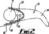
図2は、図1のPIP関節17の詳細図である。図1と同様に、指先部分16は指の中節指及び末節指に対応する。図2に見られるように、歯付きベルト18は、関節17付近に装着されたローラ30上を通過してから、指先芯32上を通過し、これはプラスチック又は金属で形成された中実体で、関節17に取り付けられる。指先芯32は、その表面に形成され、ベルト18上の歯を受けて、指先芯32とベルト18との係合を提供するように成形された窪みを有する。ベルト18の有効長は、ベルト18を指先芯32から係合解除し、ベルトを必要な方向に動作させてから、ベルトと指先芯とを再係合させることによって、ベルト上の歯の間隔に対応する目盛り付きの量だけ調節することができる。ベルトが必要に応じて係合している場合、カバー34は指の遠位部分上に配置され、ねじ36によって固定されて、ベルト18をカバー34と指先芯32との間に挟む。
FIG. 2 is a detailed view of the PIP joint 17 of FIG. As in FIG. 1, the
図3は、人工補装具の傘歯車の詳細図を提供する。人工補装具は、3本のアーム44、46、48を有するベベル支持部材42を備え、第2及び第3アーム46、48は第1アーム44に対して直角に配置され、それによって二重の1字形の輪郭を形成し、ウォーム13が第2アーム46と第3アーム48の間に配置される。図3に示すように、第1アーム44は人工補装具のハウジング6に取り付けられる。第1傘歯車10の軸が、ベベル支持部材42の第1アーム44内に設けた口を通過し、第2傘歯車11の軸が、ベベル支持部材の第2アーム46に設けた口を通過する。また、ウォーム13の軸を、第3アーム48に設けた窪みで受ける。したがって、1字形のベベル支持部材は、第1及び第2傘歯車10、11及びウォーム13を支持し、人工補装具の組立中に第1及び第2傘歯車10、11の相対的配置を容易にする。図示されていない代替形態では、ベベル支持部材42は、図3に示す第2及び第3アーム46、48の代わりに大きい1本のアームを有する。ベベル支持部材42の代替形態の大きい1本のアームは、内部でウォーム13を支持するボアを画定する。また、大きい1本のアームは、図3で図示し、それに関して説明したものとほぼ同じ方法で、第2傘歯車11及びウォーム13の軸を支持するように形成される。
FIG. 3 provides a detailed view of the bevel gear of the prosthesis. The prosthesis includes a bevel support member 42 having three
使用時には、着用者は、駆動モータ7を作動させる上述の制御手段によって指を起動する。駆動モータ7が作動すると、第1傘歯車10が回転し、これはウォーム13とともに第2傘歯車11を回転する。ウォーム13が回転するにつれ、これは固定されたウォーム歯車5の周表面で、駆動モータ7の回転方向に応じて時計回り又は反時計回りに進行する。これで、矢印24で示すように、指3が軸8の周囲で動作する。指3が軸8の周囲で下方向に動作すると、歯付きベルト18をウォーム歯車5の口19に取り付けた点と近位関節17との間の距離が減少する。これは、図1に示すように、口19がウォーム歯車の軸からずれているせいである。距離が減少するにつれ、固定長の歯付きベルト18が、コイルばね22の偏倚に抗して指先部分16を引っ張り、指先部分16を指3の残りの部分に対して時計回りに回転する。軸の周囲の指3の回転方向が逆転すると、つまり指3が上方向に動作すると、歯付きベルト18にかかる張力が解放され、ばね22が指先部分16に偏倚力を加えて、指先部分を図1に示す延在位置に戻す。
In use, the wearer activates the finger by the above-described control means that operates the drive motor 7. When the drive motor 7 is activated, the
Claims (16)
前記ウォーム(13)及び前記駆動モータ(7)が前記ウォーム歯車の軸(8)の対向する側に配置され、
前記ウォーム(13)は前記指部材(3)の外側に配置されていることを特徴とする人工補装具。A prosthetic device (1) providing at least one mechanically actuable finger member, wherein the prosthetic device (1) is fixed on a support member of the prosthetic device At least one finger member (3) extending substantially tangentially to the worm gear, the finger member (3) being mounted for rotation about an axis (8) of the worm gear. The finger member (3) includes a drive motor (7) operable to drive the worm (13), and the worm is activated when the drive motor (7) is activated during use of the prosthesis. In the prosthesis that engages the worm gear (5) so that the finger member (3) operates about the worm gear (5),
The worm (13) and the drive motor (7) are arranged on opposite sides of the shaft (8) of the worm gear ;
Prosthesis the worm (13), characterized that you have placed outside of the finger member (3).
前記複数の指又は指のグループの動作の独立性を可能にするように構成された制御手段が設けられている、請求項1〜13のいずれか一項に記載の人工補装具。A plurality of fingers each having at least one finger member;
The prosthetic device according to any one of the preceding claims, provided with control means configured to allow independence of movement of the plurality of fingers or groups of fingers.
前記人工補装具(1)の支持部材上のウォーム歯車(5)と、A worm gear (5) on a support member of the prosthesis (1);
駆動モータ(7)を備える指部材(3)であって、前記ウォーム歯車の軸(8)の周囲で回転するように装着された、前記指部材(3)と、A finger member (3) comprising a drive motor (7), wherein the finger member (3) is mounted for rotation about an axis (8) of the worm gear;
前記駆動モータ(7)に結合され、前記ウォーム歯車(5)と係合するウォーム(13)であって、前記人工補装具(1)の使用時に前記駆動モータ(7)が作動すると、前記指部材(3)が前記ウォーム歯車(5)を中心として動作し、前記指部材(3)は前記支持部材に対して回転し、前記ウォーム(13)は前記指部材(3)の外側に配置されている、前記ウォーム(13)と、A worm (13) coupled to the drive motor (7) and engaged with the worm gear (5), wherein when the drive motor (7) is activated when the artificial prosthesis (1) is used, the finger The member (3) operates around the worm gear (5), the finger member (3) rotates with respect to the support member, and the worm (13) is disposed outside the finger member (3). The worm (13),
前記駆動モータ(7)の動作を前記ウォーム(13)に結合するように構成された伝達手段(10,11)と、Transmission means (10, 11) configured to couple the operation of the drive motor (7) to the worm (13);
を有し、Have
前記伝達手段(10,11)は、前記ウォームの回転軸が前記駆動モータ(7)の回転軸に対して傾斜するように構成されていることを特徴とする、人工補装具。The prosthesis is characterized in that the transmission means (10, 11) is configured such that the rotating shaft of the worm is inclined with respect to the rotating shaft of the drive motor (7).
Applications Claiming Priority (3)
| Application Number | Priority Date | Filing Date | Title |
|---|---|---|---|
| GB0524284.7 | 2005-11-29 | ||
| GBGB0524284.7A GB0524284D0 (en) | 2005-11-29 | 2005-11-29 | Prosthesis |
| PCT/GB2006/002680 WO2007063266A1 (en) | 2005-11-29 | 2006-07-19 | Prostheses with mechanically operable digit members |
Publications (2)
| Publication Number | Publication Date |
|---|---|
| JP2009517155A JP2009517155A (en) | 2009-04-30 |
| JP4841633B2 true JP4841633B2 (en) | 2011-12-21 |
Family
ID=35601431
Family Applications (1)
| Application Number | Title | Priority Date | Filing Date |
|---|---|---|---|
| JP2008542815A Expired - Fee Related JP4841633B2 (en) | 2005-11-29 | 2006-07-19 | Prosthesis with mechanically actuable finger |
Country Status (10)
| Country | Link |
|---|---|
| US (1) | US8808397B2 (en) |
| EP (2) | EP1962731B1 (en) |
| JP (1) | JP4841633B2 (en) |
| CN (1) | CN101321508B (en) |
| AT (2) | ATE525042T1 (en) |
| DE (1) | DE602006010239D1 (en) |
| DK (2) | DK2135588T3 (en) |
| ES (2) | ES2373847T3 (en) |
| GB (1) | GB0524284D0 (en) |
| WO (1) | WO2007063266A1 (en) |
Cited By (1)
| Publication number | Priority date | Publication date | Assignee | Title |
|---|---|---|---|---|
| US10682085B2 (en) | 2014-07-18 | 2020-06-16 | Becton, Dickinson And Company | Lancet device with first-drop removal |
Families Citing this family (55)
| Publication number | Priority date | Publication date | Assignee | Title |
|---|---|---|---|---|
| US8956421B2 (en) | 2007-02-06 | 2015-02-17 | Deka Products Limited Partnership | Dynamic support apparatus and system |
| GB0524284D0 (en) | 2005-11-29 | 2006-01-04 | Touch Emas Ltd | Prosthesis |
| CA2679616C (en) | 2007-02-06 | 2015-10-06 | David E. Altobelli | Dynamic support apparatus |
| US8864845B2 (en) | 2007-02-06 | 2014-10-21 | DEKA Limited Partnership | System for control of a prosthetic device |
| US9114030B2 (en) | 2007-02-06 | 2015-08-25 | Deka Products Limited Partnership | System for control of a prosthetic device |
| US9114028B2 (en) * | 2007-02-06 | 2015-08-25 | Deka Products Limited Partnership | Arm prosthetic device |
| US11291562B2 (en) | 2007-02-06 | 2022-04-05 | Deka Products Limited Partnership | Arm prosthetic device |
| WO2008098059A2 (en) | 2007-02-06 | 2008-08-14 | Deka Integrated Solutions Corp. | Method and apparatus for control of a prosthetic |
| DE102008056520B4 (en) | 2008-11-08 | 2017-10-19 | Stefan Schulz | finger member |
| GB0910920D0 (en) | 2009-06-24 | 2009-08-05 | Touch Emas Ltd | Method of controlling a prosthesis |
| GB0916895D0 (en) | 2009-09-25 | 2009-11-11 | Touch Emas Ltd | Prosthetic apparatus and method |
| PL221882B1 (en) | 2010-01-14 | 2016-06-30 | Michał Wasielewski | Modular human hand prosthesis with modular, mechanically independent finger modules |
| DE102010005690B4 (en) * | 2010-01-25 | 2012-04-19 | Otto Bock Healthcare Products Gmbh | Adjusting device for a prosthetic device and method for operating such an adjusting device |
| GB201003573D0 (en) | 2010-03-04 | 2010-04-21 | Touch Emas Ltd | Hand prothesis |
| JP5795171B2 (en) * | 2011-03-04 | 2015-10-14 | 株式会社ツバキE&M | Reduction gear and its series |
| DE102011110101A1 (en) * | 2011-08-13 | 2013-02-14 | Stefan Schulz | Method for moving and holding a phalanx |
| GB201114264D0 (en) | 2011-08-18 | 2011-10-05 | Touch Emas Ltd | Improvements in or relating to prosthetics and orthotics |
| GB201116060D0 (en) | 2011-09-16 | 2011-11-02 | Touch Emas Ltd | Method of controlling a prosthesis |
| GB201116069D0 (en) | 2011-09-16 | 2011-11-02 | Touch Emas Ltd | Method and apparatus for controlling a prosthetic device |
| DE102011116751A1 (en) * | 2011-10-24 | 2013-04-25 | Fraunhofer-Gesellschaft zur Förderung der angewandten Forschung e.V. | Active knee prosthesis with bevel helical gear |
| GB201213030D0 (en) | 2012-07-23 | 2012-09-05 | Touch Emas Ltd | Improvements in or relating to prosthetics and orthotics |
| US11351042B2 (en) | 2012-08-12 | 2022-06-07 | 5Th Element Limited | Automated hand |
| ITPI20130004A1 (en) * | 2013-01-16 | 2014-07-17 | Machinale S R L Fab | PROSTHETIC STRUCTURE FOR HAND AMPUTATION |
| GB201302025D0 (en) | 2013-02-05 | 2013-03-20 | Touch Emas Ltd | Improvements in or relating to prosthetics |
| JP5655877B2 (en) * | 2013-02-12 | 2015-01-21 | 株式会社安川電機 | Joint mechanism and robot |
| DE102013007539A1 (en) * | 2013-05-03 | 2014-11-06 | Otto Bock Healthcare Products Gmbh | Artificial finger |
| EP3102158B1 (en) | 2014-02-04 | 2019-06-12 | Rehabilitation Institute of Chicago | Modular and lightweight prosthesis components |
| GB201403265D0 (en) * | 2014-02-25 | 2014-04-09 | Touch Emas Ltd | Prosthetic digit for use with touchscreen devices |
| GB201408253D0 (en) | 2014-05-09 | 2014-06-25 | Touch Emas Ltd | Systems and methods for controlling a prosthetic hand |
| GB201417541D0 (en) | 2014-10-03 | 2014-11-19 | Touch Bionics Ltd | Wrist device for a prosthetic limb |
| CN104625798A (en) * | 2014-12-09 | 2015-05-20 | 重庆迪科汽车研究有限公司 | Three-sided stable clamping mechanism |
| US10260566B2 (en) | 2015-05-13 | 2019-04-16 | Mark H. Salerno | Marine antenna actuator |
| US9974667B1 (en) | 2015-05-28 | 2018-05-22 | Blain Joseph Cazenave | Electromagnetic actuation mechanism for individual digit control of an artificial hand |
| US20160367383A1 (en) * | 2015-06-19 | 2016-12-22 | Rehabilitation Institute Of Chicago | Lockable Finger System and Related Methods |
| CN105078624A (en) * | 2015-09-06 | 2015-11-25 | 丹阳假肢厂有限公司 | Electric two-dimensional bionic hand thumb |
| CN105232192A (en) * | 2015-09-06 | 2016-01-13 | 丹阳假肢厂有限公司 | Middle and index finger structure of bionic hand |
| CN106038008B (en) * | 2015-11-18 | 2018-03-02 | 杭州若比邻机器人科技有限公司 | The base finger joint of artificial limb finger and the attachment structure in base joint |
| CN106038003B (en) * | 2015-11-18 | 2018-03-02 | 杭州若比邻机器人科技有限公司 | Artificial limb thumb |
| CN105584554B (en) * | 2015-12-17 | 2018-05-04 | 常州大学 | Anthropomorphic robot two-freedom series-parallel connection vibration damping machinery foot |
| CN105965535B (en) * | 2016-05-04 | 2019-01-18 | 上海科生假肢有限公司 | Bionic hand carpomaetacarpal joint of thumb |
| EP3506857A1 (en) | 2016-09-02 | 2019-07-10 | Touch Bionics Limited | Systems and methods for prosthetic wrist rotation |
| US11185426B2 (en) | 2016-09-02 | 2021-11-30 | Touch Bionics Limited | Systems and methods for prosthetic wrist rotation |
| DE102017005762B4 (en) | 2017-06-20 | 2020-02-13 | Stefan Schulz | finger member |
| US10973660B2 (en) | 2017-12-15 | 2021-04-13 | Touch Bionics Limited | Powered prosthetic thumb |
| CN108214537B (en) * | 2018-02-02 | 2023-07-18 | 昆明理工大学 | Multifunctional flexible grabbing mechanism |
| US11185427B2 (en) * | 2018-04-27 | 2021-11-30 | Psyonic, Inc. | Compliant four-bar linkage mechanism for a robotic finger |
| GB2577499B (en) * | 2018-09-25 | 2020-11-18 | Covvi Ltd | A mechanical hand |
| US10905570B2 (en) | 2018-11-19 | 2021-02-02 | The Regents Of The University Of Colorado, A Body Corporate | Prosthetic partial fingers |
| US11547581B2 (en) | 2018-12-20 | 2023-01-10 | Touch Bionics Limited | Energy conservation of a motor-driven digit |
| CN109758275B (en) * | 2019-01-22 | 2023-11-10 | 内蒙古恩德莱康复器具有限公司 | Combined under-actuated bionic artificial finger with driving rope and four-bar mechanism |
| RU2719658C1 (en) * | 2019-02-20 | 2020-04-21 | Общество с ограниченной ответственностью "МОТОРИКА" | Gripping mechanism of pedicle single-seam bioelectric prosthesis of upper limb |
| US11399967B2 (en) | 2019-03-29 | 2022-08-02 | Psyonic, Inc. | System and method for a prosthetic hand having sensored brushless motors |
| US11931270B2 (en) | 2019-11-15 | 2024-03-19 | Touch Bionics Limited | Prosthetic digit actuator |
| US20230022882A1 (en) | 2019-12-19 | 2023-01-26 | Touch Bionics Limited | Electromyography and motion based control of upper limb prosthetics |
| CN117323074B (en) * | 2023-12-01 | 2024-03-29 | 中国科学技术大学 | Wearable prosthetic glove control method and system |
Family Cites Families (21)
| Publication number | Priority date | Publication date | Assignee | Title |
|---|---|---|---|---|
| DE309367C (en) | ||||
| US2592842A (en) * | 1948-07-10 | 1952-04-15 | Samuel W Alderson | Shoulder harness for artificial arms |
| US3509583A (en) * | 1965-09-09 | 1970-05-05 | Bendix Corp | Electro-mechanical hand having tactile sensing means |
| JPS5128872Y1 (en) * | 1970-08-26 | 1976-07-21 | ||
| US3683423A (en) * | 1971-01-19 | 1972-08-15 | Russell S Crapanzano | Gravity activated prosthetic device |
| US3837010A (en) * | 1972-03-16 | 1974-09-24 | Parke Davis & Co | Prosthetic elbow with resilient locking assembly |
| US3922930A (en) * | 1974-12-23 | 1975-12-02 | Nasa | Remotely operable articulated manipulator |
| DE2607499C3 (en) * | 1976-02-25 | 1982-04-08 | Messerschmitt-Bölkow-Blohm GmbH, 8000 München | Drive device for the fingers of an artificial hand |
| US4623354A (en) * | 1984-10-22 | 1986-11-18 | Northwestern University | Myoelectrically controlled artificial hand |
| US4822238A (en) * | 1986-06-19 | 1989-04-18 | Westinghouse Electric Corp. | Robotic arm |
| US5062673A (en) * | 1988-12-28 | 1991-11-05 | Kabushiki Kaisha Toyota Chuo Kenkyusho | Articulated hand |
| US4946380A (en) * | 1989-05-30 | 1990-08-07 | University Of Southern California | Artificial dexterous hand |
| JP2648230B2 (en) * | 1990-09-20 | 1997-08-27 | 科学技術振興事業団 | manipulator |
| GB9404830D0 (en) | 1994-03-12 | 1994-04-27 | Lothian Health Board | Hand prosthesis |
| GB9722403D0 (en) * | 1997-10-24 | 1997-12-24 | Royal Infirmary Of Edinburgh N | Upper limb prosthesis |
| DE19854762C2 (en) | 1998-11-27 | 2002-07-18 | Marc Franke | Artificial hand |
| SE0102833D0 (en) * | 2001-08-27 | 2001-08-27 | Bergomed Ab | Drive device at a finger prosthesis |
| SE0102831D0 (en) * | 2001-08-27 | 2001-08-27 | Bergomed Ab | Device for a hand prosthesis |
| JP3893453B2 (en) * | 2002-04-16 | 2007-03-14 | 独立行政法人産業技術総合研究所 | Prosthetic hand |
| GB0524284D0 (en) | 2005-11-29 | 2006-01-04 | Touch Emas Ltd | Prosthesis |
| DE102005061312A1 (en) * | 2005-12-20 | 2007-08-16 | Otto Bock Healthcare Ip Gmbh & Co. Kg | hand prosthesis |
-
2005
- 2005-11-29 GB GBGB0524284.7A patent/GB0524284D0/en not_active Ceased
-
2006
- 2006-07-16 US US12/085,608 patent/US8808397B2/en active Active
- 2006-07-19 ES ES09012179T patent/ES2373847T3/en active Active
- 2006-07-19 DK DK09012179.9T patent/DK2135588T3/en active
- 2006-07-19 EP EP06765015A patent/EP1962731B1/en active Active
- 2006-07-19 WO PCT/GB2006/002680 patent/WO2007063266A1/en active Application Filing
- 2006-07-19 AT AT09012179T patent/ATE525042T1/en not_active IP Right Cessation
- 2006-07-19 DE DE602006010239T patent/DE602006010239D1/en active Active
- 2006-07-19 EP EP09012179A patent/EP2135588B1/en active Active
- 2006-07-19 AT AT06765015T patent/ATE447381T1/en not_active IP Right Cessation
- 2006-07-19 JP JP2008542815A patent/JP4841633B2/en not_active Expired - Fee Related
- 2006-07-19 ES ES06765015T patent/ES2336027T3/en active Active
- 2006-07-19 DK DK06765015.0T patent/DK1962731T3/en active
- 2006-07-19 CN CN2006800447184A patent/CN101321508B/en active Active
Cited By (2)
| Publication number | Priority date | Publication date | Assignee | Title |
|---|---|---|---|---|
| US10682085B2 (en) | 2014-07-18 | 2020-06-16 | Becton, Dickinson And Company | Lancet device with first-drop removal |
| JP7189113B2 (en) | 2014-07-18 | 2022-12-13 | ベクトン・ディキンソン・アンド・カンパニー | Lancet device for removing the first droplet |
Also Published As
| Publication number | Publication date |
|---|---|
| EP1962731A1 (en) | 2008-09-03 |
| DK1962731T3 (en) | 2010-03-22 |
| EP2135588B1 (en) | 2011-09-21 |
| EP1962731B1 (en) | 2009-11-04 |
| WO2007063266A1 (en) | 2007-06-07 |
| GB0524284D0 (en) | 2006-01-04 |
| DK2135588T3 (en) | 2012-01-23 |
| EP2135588A2 (en) | 2009-12-23 |
| ATE525042T1 (en) | 2011-10-15 |
| ATE447381T1 (en) | 2009-11-15 |
| US20100036507A1 (en) | 2010-02-11 |
| ES2336027T3 (en) | 2010-04-07 |
| EP2135588A3 (en) | 2009-12-30 |
| CN101321508B (en) | 2011-03-23 |
| EP2135588A9 (en) | 2010-02-24 |
| CN101321508A (en) | 2008-12-10 |
| DE602006010239D1 (en) | 2009-12-17 |
| US8808397B2 (en) | 2014-08-19 |
| JP2009517155A (en) | 2009-04-30 |
| ES2373847T3 (en) | 2012-02-09 |
Similar Documents
| Publication | Publication Date | Title |
|---|---|---|
| JP4841633B2 (en) | Prosthesis with mechanically actuable finger | |
| US11654034B2 (en) | Hand assembly for an arm prosthetic device | |
| JP4045308B2 (en) | Prosthetic hand | |
| EP2542189B1 (en) | Hand prosthesis | |
| US11259941B2 (en) | Prosthetic feedback apparatus and method | |
| EP2755606B1 (en) | A prosthesis or an orthosis and a method for controlling a prosthesis or an orthosis | |
| EP2061633B1 (en) | Rotary actuator arrangement | |
| ES2928990T3 (en) | mechanical hand | |
| US20230248544A1 (en) | Arm prosthetic device | |
| ES2928960T3 (en) | mechanical hand | |
| JPH0871977A (en) | Robot device | |
| WO1999013807A1 (en) | Manipulator |
Legal Events
| Date | Code | Title | Description |
|---|---|---|---|
| A621 | Written request for application examination |
Free format text: JAPANESE INTERMEDIATE CODE: A621 Effective date: 20090609 |
|
| A977 | Report on retrieval |
Free format text: JAPANESE INTERMEDIATE CODE: A971007 Effective date: 20110307 |
|
| A131 | Notification of reasons for refusal |
Free format text: JAPANESE INTERMEDIATE CODE: A131 Effective date: 20110315 |
|
| A521 | Request for written amendment filed |
Free format text: JAPANESE INTERMEDIATE CODE: A523 Effective date: 20110613 |
|
| TRDD | Decision of grant or rejection written | ||
| A01 | Written decision to grant a patent or to grant a registration (utility model) |
Free format text: JAPANESE INTERMEDIATE CODE: A01 Effective date: 20110906 |
|
| A01 | Written decision to grant a patent or to grant a registration (utility model) |
Free format text: JAPANESE INTERMEDIATE CODE: A01 |
|
| A61 | First payment of annual fees (during grant procedure) |
Free format text: JAPANESE INTERMEDIATE CODE: A61 Effective date: 20111004 |
|
| R150 | Certificate of patent or registration of utility model |
Free format text: JAPANESE INTERMEDIATE CODE: R150 |
|
| FPAY | Renewal fee payment (event date is renewal date of database) |
Free format text: PAYMENT UNTIL: 20141014 Year of fee payment: 3 |
|
| R250 | Receipt of annual fees |
Free format text: JAPANESE INTERMEDIATE CODE: R250 |
|
| R250 | Receipt of annual fees |
Free format text: JAPANESE INTERMEDIATE CODE: R250 |
|
| R250 | Receipt of annual fees |
Free format text: JAPANESE INTERMEDIATE CODE: R250 |
|
| LAPS | Cancellation because of no payment of annual fees |