JP4827981B2 - Method and system for positioning an object from a first posture to a second posture - Google Patents
Method and system for positioning an object from a first posture to a second posture Download PDFInfo
- Publication number
- JP4827981B2 JP4827981B2 JP2010121174A JP2010121174A JP4827981B2 JP 4827981 B2 JP4827981 B2 JP 4827981B2 JP 2010121174 A JP2010121174 A JP 2010121174A JP 2010121174 A JP2010121174 A JP 2010121174A JP 4827981 B2 JP4827981 B2 JP 4827981B2
- Authority
- JP
- Japan
- Prior art keywords
- image
- posture
- display device
- change
- positioning
- Prior art date
- Legal status (The legal status is an assumption and is not a legal conclusion. Google has not performed a legal analysis and makes no representation as to the accuracy of the status listed.)
- Active
Links
Images


Classifications
-
- A—HUMAN NECESSITIES
- A61—MEDICAL OR VETERINARY SCIENCE; HYGIENE
- A61N—ELECTROTHERAPY; MAGNETOTHERAPY; RADIATION THERAPY; ULTRASOUND THERAPY
- A61N5/00—Radiation therapy
- A61N5/10—X-ray therapy; Gamma-ray therapy; Particle-irradiation therapy
- A61N5/1048—Monitoring, verifying, controlling systems and methods
- A61N5/1049—Monitoring, verifying, controlling systems and methods for verifying the position of the patient with respect to the radiation beam
- A61N2005/1061—Monitoring, verifying, controlling systems and methods for verifying the position of the patient with respect to the radiation beam using an x-ray imaging system having a separate imaging source
-
- A—HUMAN NECESSITIES
- A61—MEDICAL OR VETERINARY SCIENCE; HYGIENE
- A61N—ELECTROTHERAPY; MAGNETOTHERAPY; RADIATION THERAPY; ULTRASOUND THERAPY
- A61N5/00—Radiation therapy
- A61N5/10—X-ray therapy; Gamma-ray therapy; Particle-irradiation therapy
- A61N5/1048—Monitoring, verifying, controlling systems and methods
- A61N5/1064—Monitoring, verifying, controlling systems and methods for adjusting radiation treatment in response to monitoring
- A61N5/1069—Target adjustment, e.g. moving the patient support
Description
本発明は、包括的には物体を位置決めするための方法に関し、より詳細には、物体の位置合わせされた画像に基づいて、該物体を位置決めするための方法に関する。 The present invention relates generally to a method for positioning an object, and more particularly to a method for positioning an object based on a registered image of the object.
放射線療法
放射線療法は、高エネルギーの電離放射線を、健常組織に害を与えないようにしながら患者の体内の病変組織、たとえば腫瘍に向ける。放射線療法の1つの形態は粒子線療法である。粒子線療法では、最大照射の深さを制御することができる。一方で、腫瘍の場所、特に、脳、肝臓、肺、胃、及び心臓のような重要な臓器の近くの腫瘍の場所を、正確に求める必要がある。したがって、治療計画に従って、患者の全組織構造を位置決めすることが所望されている。
Radiation therapy Radiation therapy directs high-energy ionizing radiation to a diseased tissue, such as a tumor, in a patient's body while not harming healthy tissue. One form of radiation therapy is particle beam therapy. In particle beam therapy, the maximum irradiation depth can be controlled. On the other hand, there is a need to accurately determine the location of the tumor, particularly in the vicinity of important organs such as the brain, liver, lungs, stomach, and heart. Therefore, it is desirable to position the entire tissue structure of the patient according to the treatment plan.
放射線療法は、高エネルギーの電離放射線を、健常組織に害を与えないようにしながら人体内の病変組織に向ける。放射線療法の1つの形態は粒子線療法である。粒子線療法では、最大照射の深さを制御することができる。一方で、従来の光子ベースの放射線療法とは異なり、線量のピークは組織内に位置し、粒子線のエネルギー及び粒子線の経路内の組織によって、ピーク線量の正確な深さ位置が求められる。したがって、目標組織の場所を正確に求める必要がある。したがって、治療計画において指定される治療ビームの幾何学的な位置合わせに従って、患者の全組織構造を正確に位置決めすることが所望されている。 Radiation therapy directs high-energy ionizing radiation to the diseased tissue in the human body without causing harm to healthy tissue. One form of radiation therapy is particle beam therapy. In particle beam therapy, the maximum irradiation depth can be controlled. On the other hand, unlike conventional photon-based radiation therapy, the dose peak is located in the tissue, and the precise depth position of the peak dose is determined by the energy of the particle beam and the tissue in the path of the particle beam. Therefore, it is necessary to accurately determine the location of the target organization. Accordingly, it is desirable to accurately position the entire tissue structure of the patient according to the geometric alignment of the treatment beam specified in the treatment plan.
放射線療法は、癌治療の一環として電離放射線を使用して悪性細胞を抑制する。放射線療法を、根治的癌治療又は補助的癌治療に使用することができる。放射線療法は、治癒が不可能であり、局所的な疾患の抑制若しくは症状の軽減を目的とする場合、苦痛緩和治療として使用され、又は療法が生存ベネフィットを有し、治癒可能であり得る場合、治癒効果のある治療として使用される。放射線療法は、悪性腫瘍の治療に使用され、一次療法として使用することができる。放射線療法を、手術、化学療法、ホルモン療法、又はそれらの組合せと組み合わせることも一般的である。 Radiation therapy uses ionizing radiation as part of cancer treatment to suppress malignant cells. Radiation therapy can be used for curative cancer treatment or adjunct cancer treatment. Radiation therapy cannot be cured and is used as a pain relief treatment if it is intended to suppress local disease or reduce symptoms, or if the therapy has a survival benefit and can be cured, Used as a curative treatment. Radiation therapy is used to treat malignant tumors and can be used as a primary therapy. It is also common to combine radiation therapy with surgery, chemotherapy, hormonal therapy, or a combination thereof.
腫瘍学的ケースでは、放射線療法は一般的に主に腫瘍に適用される。近くのリンパ節が腫瘍と臨床的に関連する場合、又は転移の危険性があると考えられる場合、照射野はそれらのリンパ節も含む場合がある。患者の配置の不確かさ及び内部の腫瘍の動きを考慮に入れるために、腫瘍の周りの余分な正常組織を含める必要がある。 In oncological cases, radiation therapy is generally applied primarily to tumors. If nearby lymph nodes are clinically associated with the tumor or are considered at risk of metastasis, the field may also include those lymph nodes. In order to take into account patient placement uncertainty and internal tumor movement, it is necessary to include extra normal tissue around the tumor.
放射線療法は、通常、数週間、たとえば3週間又は4週間にわたる複数の短いセッションにおいて提供され、患者が治療間に回復することを可能にすることに留意しなければならない。このため、同一の配置を達成するのが困難である。したがって、放射線治療士に対し、ビームに対してどのように患者を配置するかを示すために、患者の皮膚は通例、治療計画の間、消えないインクでマーク付けされる。 It should be noted that radiation therapy is usually provided in multiple short sessions over several weeks, eg 3 or 4 weeks, allowing the patient to recover between treatments. For this reason, it is difficult to achieve the same arrangement. Thus, to indicate to the radiation therapist how to position the patient relative to the beam, the patient's skin is typically marked with an indelible ink during the treatment plan.
配置の不確かさは、内部運動、たとえば呼吸及び膀胱充満、並びに腫瘍の場所に対する外部の皮膚マークの移動によっても引き起こされ得る。 Placement uncertainty can also be caused by internal movements, such as breathing and bladder filling, and movement of external skin marks relative to the tumor location.
腫瘍を治療するために放射線が通過しなくてはならない皮膚又は臓器のような正常組織に害を与えないようにするために、成形された放射線ビームが幾つかの照射角から腫瘍において交わるように照準を定められ、腫瘍において周囲の健常組織よりもはるかに大きい吸収線量を提供する。通常、放射源は患者の周りを回転するガントリ上に配置される。目標は、ビームが回転するときのビームの中心軸のアイソセンタに腫瘍を配置し、それによってビームが常に腫瘍を通過し、健常組織を通過する頻度がはるかに低くなるようにすることである。 In order to prevent harm to normal tissues such as skin or organs through which radiation must pass to treat the tumor, the shaped radiation beam intersects the tumor from several angles of irradiation. It is aimed and provides a much larger absorbed dose in the tumor than the surrounding healthy tissue. Typically, the radiation source is placed on a gantry that rotates around the patient. The goal is to place the tumor at the isocenter of the central axis of the beam as it rotates so that the beam always passes through the tumor and is much less frequently passed through healthy tissue.
患者の位置決め
放射線療法における一般的な問題は、治療計画に従って、患者を放射線機器に対して位置決めすることである。治療プランは通常、高解像度のコンピュータ断層撮影(CT)スキャンを使用して作成され、組織の密度を表す三次元(3D)ボリュームデータを含む。治療の間、放射線機器に対して、患者を、腫瘍が放射線ビームの中央軸のアイソセンタに位置決めされ、したがって計画された放射線量が腫瘍に送達されることを確実にするように位置決めする必要がある。
Patient Positioning A common problem in radiation therapy is positioning the patient relative to the radiation equipment according to a treatment plan. Treatment plans are typically created using high-resolution computed tomography (CT) scans and include three-dimensional (3D) volume data representing tissue density. During treatment, the patient needs to be positioned relative to the radiology device to ensure that the tumor is positioned at the isocenter of the central axis of the radiation beam, and thus the planned radiation dose is delivered to the tumor. .
この目標を達成するために、通例1組のX線が取得され、CTボリュームの予測ビューと比較される。位置決めの誤りが推定され、患者は正しい位置に動かされる。現在この位置決めは手動又は半自動で実施される。 To achieve this goal, typically a set of x-rays is acquired and compared to a predicted view of the CT volume. Positioning errors are estimated and the patient is moved to the correct position. Currently, this positioning is performed manually or semi-automatically.
手動の方法は時間がかかり、6自由度(6−DOF)にわたって操作される、物体の3D形状を理解する必要がある。療法士は患者を伴ったカウチを動かし、動かした後に毎回X線画像を取得する。この手順は長時間を要すると共に、大線量の治療効果のないX線放射を患者に照射する可能性がある。 The manual method is time consuming and requires an understanding of the 3D shape of the object that is manipulated over 6 degrees of freedom (6-DOF). The therapist moves the couch with the patient and acquires an X-ray image every time after moving. This procedure is time consuming and can irradiate the patient with large doses of ineffective X-ray radiation.
自動的な方法は、患者を不正確に位置決めする場合がある。したがって、放射線治療士は、自動位置決めの結果を検査する必要がある。さらに、マウス又はトラックボールのような従来の入力装置を使用して初期状態を設定するか又は点対応をマークするために、治療士がレンダリングされた3Dボリュームを操作することが必要であることは、以下の理由で困難且つ非直感的である。 Automatic methods may position the patient incorrectly. Therefore, the radiotherapist needs to examine the result of the automatic positioning. In addition, it is necessary for the therapist to manipulate the rendered 3D volume to set the initial state or mark point correspondence using a conventional input device such as a mouse or trackball. It is difficult and unintuitive for the following reasons.
CTスキャンデータは、6−DOFを用いて操作する必要がある3Dボリュームを形成する。2Dマニピュレータ(マウス)及び2D画像を使用したこのような操作は困難である。 The CT scan data forms a 3D volume that needs to be manipulated using 6-DOF. Such an operation using a 2D manipulator (mouse) and 2D images is difficult.
従来のユーザインタフェースを用いる場合、マウス及び表示装置が同じ場所になく、これによって対応を特定することが困難になる。 When using a conventional user interface, the mouse and the display device are not in the same location, which makes it difficult to identify the correspondence.
本発明の目的は、物体の画像に基づいて該物体を位置決めするためのシステム及び方法を提供することである。 An object of the present invention is to provide a system and method for positioning an object based on an image of the object.
本発明の1つの実施の形態は、物体を第1の姿勢から第2の姿勢に位置決めするための方法を説明する。本方法は、第1の画像及び第2の画像を表示装置上に同時に表示し、第1の画像は物体の第1の姿勢を表し、第2の画像は物体の第2の姿勢を表す。本方法は、表示装置上の第1の画像及び第2の画像の位置合わせが該表示装置の姿勢の変化に依拠するように、該表示装置の該姿勢の変化に応じて第2の画像を更新し、該表示装置の該姿勢の変化に基づいて物体を第1の姿勢から第2の姿勢に位置決めする。 One embodiment of the present invention describes a method for positioning an object from a first posture to a second posture. The method simultaneously displays a first image and a second image on a display device, the first image representing a first attitude of the object and the second image representing a second attitude of the object. The method applies the second image in response to a change in the orientation of the display device such that the alignment of the first image and the second image on the display device depends on a change in the orientation of the display device. Updating, and positioning the object from the first posture to the second posture based on the change in the posture of the display device.
本発明の別の実施の形態は、物体を第1の姿勢から第2の姿勢に位置決めするためのシステムであって、第1の画像及び第2の画像を同時に表示するように構成される表示装置であって、第1の画像は物体の第1の姿勢を表し、第2の画像は物体の第2の姿勢を表す、表示装置と、表示装置上の第1の画像及び第2の画像の位置合わせが該表示装置の姿勢の変化に依拠するように、該表示装置の該姿勢の変化に応じて第2の画像を更新するように構成されるレンダリングエンジンと、表示装置の姿勢の変化に基づいて物体を第1の姿勢から第2の姿勢に位置決めするように構成される位置決めモジュールと、を備える、システムを説明する。 Another embodiment of the invention is a system for positioning an object from a first posture to a second posture, wherein the display is configured to simultaneously display the first image and the second image. A display device, a first image and a second image on the display device, wherein the first image represents a first posture of the object and the second image represents a second posture of the object A rendering engine configured to update the second image in response to a change in the orientation of the display device, and a change in the orientation of the display device such that the alignment of the display device depends on a change in the orientation of the display device And a positioning module configured to position an object from a first posture to a second posture based on the system.
図1は、本発明の実施の形態による、物体を第1の姿勢111から第2の姿勢121に位置決めするための方法及びシステム100を示している。本方法は、表示装置130上の第1の画像110及び第2の画像120の位置合わせに基づいて物体を位置決めする。第1の画像は物体の第1の姿勢を表し、第2の画像は物体の第2の姿勢を表し、該第1の画像及び該第2の画像は表示装置上に同時に表示される。方法100はプロセッサ101によって実行される。プロセッサは、当該技術分野において既知の、様々なモデルのためのメモリと、入力/出力インタフェースと、グラフィック処理ユニット(GPU)とを備える。
FIG. 1 illustrates a method and
第1の姿勢で位置決めされた物体から取得される(112)画像111から、第1の画像をレンダリングする(151)。第2の姿勢で位置決めされた物体から取得される(122)体積画像123から、第2の画像をレンダリングする(150)。幾つかの実施の形態において、下記で説明するように画像を比較する(410)。
The first image is rendered from the
幾つかの実施の形態において、物体は治療のために位置決めされた患者182である。1つの実施の形態では、体積画像は、治療計画中に患者から取得される詳細なコンピュータ断層撮影(CT)スキャンから構築される。他の実施の形態では、体積画像は磁気共鳴撮像(MRI)ボリューム及び陽電子放出型断層撮影(PET)によって取得される。第1の画像は、治療セッションのための配置の間に患者から取得されるX線画像から構築される。物体はいかなる任意の物体であってもよく、患者は1つの物体例に過ぎないことが理解される。 In some embodiments, the object is a patient 182 positioned for treatment. In one embodiment, the volume image is constructed from detailed computed tomography (CT) scans acquired from the patient during the treatment plan. In other embodiments, volume images are acquired by magnetic resonance imaging (MRI) volume and positron emission tomography (PET). The first image is constructed from x-ray images acquired from the patient during placement for a treatment session. It will be understood that the object may be any arbitrary object and the patient is just one example object.
物体の姿勢は3Dロケーション及び3D配向を有し、その結果6自由度(6−DOF)となる。画像は、表示装置の姿勢を変化させることによって位置合わせされる。通常、オペレータは、第2の画像を第1の画像と位置合わせしながら、6−DOFで表示装置を動かす。画像が位置合わせされた後、たとえば互いに重ね合わされた後、表示装置の姿勢の変化は、物体を第1の姿勢から第2の姿勢に位置決めする(180)ための変換、たとえば変換パラメータ155を示す。
The pose of the object has 3D location and 3D orientation, resulting in 6 degrees of freedom (6-DOF). Images are aligned by changing the orientation of the display device. Typically, the operator moves the display device with 6-DOF while aligning the second image with the first image. After the images are aligned, eg, superimposed on each other, the change in attitude of the display device indicates a transformation, eg,
本発明の背後にある着想は、古典的な子供のゲームに類似した最先端技術の解決法である。このゲームにおいて、トレイが目標の穴とビー玉を有する。手を使用してビー玉を巧みに操って現在の位置から目標の穴に入れる。しかしながら、本発明ではこれを非直感的な方法で行う。本発明では、ビー玉を定位置の現在の位置に固定し、代わりに目標の穴を巧みに操ってビー玉と位置合わせする。また、本発明では、トレイを無重力の表示装置に置き換え、穴及びビー玉を並進及び回転が可能な画像、光符号化器測定値に置き換え、正規化相互相関、Kullback-Leiblerダイバージェンス、及び他のもののような関数変換及び距離メトリックを適用して、2本の手を使用して患者に粒子線を自然に位置合わせする。 The idea behind the present invention is a state-of-the-art solution similar to classic children's games. In this game, the tray has a target hole and marbles. Use your hands to skillfully manipulate the marble from the current position into the target hole. However, the present invention does this in a non-intuitive way. In the present invention, the marble is fixed at the current position of the fixed position, and instead, the target hole is skillfully manipulated to align with the marble. Also, in the present invention, the tray is replaced with a weightless display, the holes and marbles are translated and rotated images, optical encoder measurements, normalized cross-correlation, Kullback-Leibler divergence, and others Applying such a functional transformation and distance metric, the particle beam is naturally aligned with the patient using two hands.
通常、画像113は2次元(2D)である。このため、レンダリングエンジン151は、画像を、実質的に変化させることなく表示のために送信する。しかしながら、体積画像123は3次元(3D)であり、レンダリングエンジン150によって2Dに変換される。レンダリングエンジン150は、表示装置の動きに応じて、姿勢測定モジュール160によって求められた表示装置の姿勢の変化154に基づいて体積画像から第2の画像をレンダリングする。第2の画像は表示装置の姿勢の変化に応じて更新されるため、表示装置上の第1の画像及び第2の画像の位置合わせは表示装置の姿勢の変化に依拠する。
Usually, the
図2は、第2の画像を表示装置上にレンダリングするための方法を示している。本方法は、表示装置154の姿勢の変化、たとえば並進及び回転に基づいて、第2の姿勢254の変化の結果生じる姿勢255を有する物体を表す(235)ビューパラメータ230を求める(210)。第2の姿勢の変化は、本発明の実施の形態による表示装置の姿勢の変化に対応する(250)。グラフィック処理ユニット(GPU)240は、ビューパラメータに従って、体積画像123から第2の画像をレンダリングする。
FIG. 2 illustrates a method for rendering a second image on a display device. The method determines (210) a
たとえば、1つの実施の形態において、第2の画像120は合成X線ビュー、すなわち姿勢255を有する物体からX線撮像装置によって取得されたかのようなデジタル再構成された放射線写真(DRR)画像である。
For example, in one embodiment, the
図3は、レンダリングエンジン150によって実施される座標変換300を示している。体積画像123は関連付けられる大域座標系320を有する。ビューパラメータ230は、表示装置の画像座標系330に関連付けられる。カメラ、たとえばX線撮像装置の内部パラメータ及び外部パラメータ、たとえば焦点距離、画像内の主点の場所が知られている場合、回復される必要があるパラメータは、表示装置130の姿勢154の変化のみによって求められる。
FIG. 3 shows a coordinate
表示装置は、6−DOFを有するマニピュレータ170上に固定で(rigidly)配置される。したがって、表示装置を6−DOFで動かすことができる。マニピュレータの姿勢の変化、及び間接的には表示装置の姿勢の変化が姿勢測定モジュール160によって感知される。マニピュレータの姿勢の変化は、並進パラメータ155によって記述される。1つの実施の形態では、第1の画像及び第2の画像が位置合わせされた後、並進パラメータに基づいて患者182を放射線療法のために位置決めする(180)。
The display device is arranged rigidly on a
画像の比較
図4は比較モジュールを示している。比較モジュールは、第1の画像及び第2の画像を比較して(410)、何らかの類似度メトリック、たとえばユークリッド距離、Kullback-Leibler(KL)ダイバージェンス、正規化相互相関に基づいて比較結果420を作成する。
Image Comparison FIG. 4 shows the comparison module. The comparison module compares the first image and the second image (410) and creates a
第1の画像及び第2の画像は、最初に表示されるとき、ずれている場合がある。位置合わせ工程の目的は、表示装置を動かすことによって、画像を互いに位置合わせすることである。表示装置の移動は通常、オペレータによって実施される。位置合わせを容易にするために、幾つかの実施の形態は比較結果、たとえばずれの方向及び/又はサイズを表示装置上にレンダリングする。1つの実施の形態では、ずれは表示装置上で強調表示される。別の実施の形態では、比較結果の値が表示される。さらに別の実施の形態では、ずれを示す拡張式のバーが表示装置の脇に表示される。 The first image and the second image may be misaligned when initially displayed. The purpose of the alignment process is to align the images with each other by moving the display device. The movement of the display device is usually performed by an operator. In order to facilitate alignment, some embodiments render the comparison results, eg, the direction and / or size of the deviation on the display device. In one embodiment, the deviation is highlighted on the display device. In another embodiment, the value of the comparison result is displayed. In yet another embodiment, an expandable bar indicating the misalignment is displayed beside the display device.
N−DOF
物体の位置決めの間、6−DOFは、たとえば3つの回転及び3つの並進、すなわち剛体変換に対応する。しかしながら、幾つかの実施の形態では、画像113から数週間隔てて体積画像123が取得され、画像113は非剛体変形を反映する。たとえば、軟組織の位置合わせは組織の何らかの微細な局所伸縮及び押動を必要とする場合があり、腸はガスを有する場合があり、腎臓は動く場合があり、肺は異なる膨張レベルにある場合がある。したがって、1つの実施の形態では、表示装置130はタッチセンサ式のスクリーンを備える。このため、本実施の形態によって、表示装置を動かすことによる剛体変換、及びタッチセンサ式のスクリーンを使用して画像を操作することによる非剛体補正が可能となる。
N-DOF
During the positioning of the object, the 6-DOF corresponds to, for example, three rotations and three translations, i.e. rigid transformations. However, in some embodiments, a
水平マニピュレータ
図5は、表示装置及び水平マニピュレータ500を示している。水平マニピュレータは、変形型六脚(modified hexapod)を備える(Hayward他著「Kinematic Decoupling In Mechanisms And Application To A Passive Hand Controller. J. Robotics Systems」(Witley, Vol. 10, No.5, pp. 767-790,1993))。
Horizontal Manipulator FIG. 5 shows a display device and a
マニピュレータ500は、表示装置の6−DOF操作を可能にする。マニピュレータは、上側プラットフォーム510と、下側プラットフォーム520とを備え、各プラットフォームが、反対側にある上面515及び下面525を有する。上側プラットフォームの下面は通例、下側プラットフォームの上面と位置合わせ及び離間される。
The
マニピュレータは、表示装置のための無重力緩衝を提供するための緩衝機構530をさらに備える。緩衝は、図6に示す脚アセンブリ600のシステムを使用して実施される。脚アセンブリは、表示装置の重さを補償するための長い「反重力」ばね610を備える。脚アセンブリは、上側プラットフォームが解放されるときに緩衝機構530を再度センタリングするための2つのばね、すなわち拡張補償ばね620と、圧縮補償ばね630とを備える。2つの自由に回転する玉継ぎ手541及び542が脚アセンブリをプラットフォームに接続する。1つの実施の形態では、緩衝機構は、プラットフォーム間を延在する6つの独立した脚アセンブリを備える。
The manipulator further includes a
1つの実施の形態では、上側プラットフォーム510の上面515は、表示装置130と固定で接続される表示プラットフォームとしての役割を果たす。別の実施の形態では、表示プラットフォームは下側プラットフォームの下面である。
In one embodiment, the
緩衝機構530によって、表示プラットフォームの6−DOF位置決めが可能になる。自由度のうちの任意のものに沿って表示装置を変位させるのに必要とされる力は、脚アセンブリの拡張に比例する。さらなる詳細についてはHayward他を参照されたい。
The
図7に示されているように、姿勢測定モジュールは、一方のプラットフォームに接続されたカメラ710と、他方のプラットフォーム上の較正パターン720とを備える。たとえば、1つの実施の形態では、カメラは上側プラットフォームに接続され、較正パターンは下側プラットフォームに接続される。パターン及びカメラを逆にすることができることに留意されたい。唯一問題となるのは、一方が固定であり、他方が自由に動くことである。別の実施の形態では、較正パターンは格子状パターンである。
As shown in FIG. 7, the attitude measurement module comprises a
姿勢検出器730は、カメラによって捕捉された較正パターンの画像に基づいてカメラの姿勢を求める。1つの実施の形態では、姿勢検出器はカメラのプロセッサ上で実行されている。別の実施の形態では、較正パターンは液晶ディスプレイ(LCD)において一般的に使用されるランプ及びディフューザによって裏から光を当てられ、それによってマニピュレータ500を、薄暗い環境、たとえば治療室内で使用することができるようにする。
The
較正パターンの画像を使用して、大域座標系と画像座標系との間の平面射影変換、すなわち変換パラメータ155を求める。コンピュータビジョンに基づいた推定を使用する変換パラメータを求める例は、参照により本明細書に援用される米国特許第6527395号明細書に記載されている。
Using the image of the calibration pattern, a plane projective transformation between the global coordinate system and the image coordinate system, that is, a
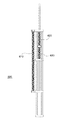
垂直マニピュレータ
図8は、可動域が増大し、垂直ディスプレイを有し、DOF変数への直接的な力のマッピングを有し、中心「アトラクタ」、すなわちシステムが力を加えられないときに戻る位置が存在しない、垂直マニピュレータを示している。
Vertical Manipulator FIG. 8 shows that the range of motion is increased, has a vertical display, has a direct force mapping to the DOF variable, and the center “attractor”, ie the position that the system returns when no force is applied A vertical manipulator that does not exist is shown.
垂直マニピュレータ800は、6−DOF操作のために操作装置に接続された表示プラットフォーム810を備える。姿勢測定モジュールは回転光符号化器820を備える。垂直in/out変位は、ケーブル取り付け具を有する回転車輪によって符号化される。この動きは、2つの回転及び1つのin/out変位の配合として感知される。横方向の線形変位センサが存在しないことに留意されたい。6つの較正された回転測定値のセットから、運動学的連鎖に沿って回転を伝播することによって変換パラメータを計算する。
The
垂直マニピュレータは、表示プラットフォームに接続された3−DOFのジンバルアセンブリ830と、垂直に配向された中心柱840とを備える。垂直マニピュレータは、ジンバルアセンブリを中心柱に連結させる揺動アーム850をさらに備える。揺動アームは中心柱を中心に回転して、中心柱を垂直方向に上下に摺動すると共に、水平方向に拡張又は収縮するようになっている。
The vertical manipulator includes a 3-
1つの実施の形態では、揺動アームは支持体860に接続され、開口865を通じて水平方向に摺動するように構成される。次いで、支持体が中心柱の周りに位置決めされ、揺動アームが垂直方向に摺動することを可能にする。
In one embodiment, the swing arm is connected to the
1つの実施の形態では、表示プラットフォームは4つの回転及び2つの並進を有し、目標の3回転及び3並進系と直接対応しない。この実施の形態では、表示プラットフォームの横方向の並進は、中心柱845を中心とした回転、揺動アームの外方向の拡張、及び回転845と反対方向における垂直軸を中心としたジンバル回転によって達成される。
In one embodiment, the display platform has four rotations and two translations and does not directly correspond to the target three-rotation and three-translation system. In this embodiment, the lateral translation of the display platform is achieved by rotation about the
1つの実施の形態では、垂直変位は約60キロの定荷重を必要とする。荷重は変化しないため、揺動アームの分離及びカンチレバー効果の除去に起因して、揺動アーム及びジンバルアセンブリを平衡させるのに必要なのは静重量による静的補償のみである。 In one embodiment, the vertical displacement requires a constant load of about 60 kg. Since the load does not change, due to the separation of the swing arm and the removal of the cantilever effect, only static compensation by static weight is required to balance the swing arm and gimbal assembly.
本発明を好ましい実施の形態の例として説明してきたが、本発明の精神及び範囲内で様々な他の適応及び変更を行うことができることは理解されたい。したがって、添付の特許請求の範囲の目的は、本発明の真の精神及び範囲内に入るすべての変形及び変更を包含することである。 Although the invention has been described by way of examples of preferred embodiments, it is to be understood that various other adaptations and modifications can be made within the spirit and scope of the invention. Accordingly, it is the object of the appended claims to cover all modifications and variations that fall within the true spirit and scope of the invention.
Claims (19)
前記物体の前記第1の姿勢を表す第1の画像及び前記物体の前記第2の姿勢を表す第2の画像を表示装置上に同時に表示するステップと、
前記表示装置上の前記第1の画像及び前記第2の画像の位置合わせが前記表示装置の姿勢の変化に依拠するように、前記表示装置の姿勢の変化に応じて前記第2の画像を更新するステップと、
前記表示装置の姿勢の変化に基づいて前記物体を前記第1の姿勢から前記第2の姿勢に位置決めするステップと
を含む、物体を第1の姿勢から第2の姿勢に位置決めするための方法。 A method for positioning an object from a first posture to a second posture, said method being performed by a computer,
Simultaneously displaying a first image representing the first posture of the object and a second image representing the second posture of the object on a display device;
Updating the second image in response to a change in the attitude of the display device such that the alignment of the first image and the second image on the display device depends on a change in the attitude of the display device And steps to
Positioning the object from the first posture to the second posture based on a change in posture of the display device. A method for positioning the object from the first posture to the second posture.
前記第2の姿勢を有する前記物体から取得された体積画像から前記第2の画像をレンダリングするステップとをさらに含む
請求項1記載の方法。 Rendering the first image from an image obtained from the object having the first orientation;
The method of claim 1, further comprising: rendering the second image from a volume image acquired from the object having the second pose.
前記表示装置の姿勢の変化を求めること、
前記表示装置の姿勢の変化に対応する、前記第2の姿勢の変化の結果生じる姿勢を有する前記物体を表すビューパラメータを求めること、及び
前記ビューパラメータに従って前記体積画像から前記第2の画像をレンダリングすることをさらに含む
請求項2記載の方法。 The updating step includes:
Determining a change in posture of the display device;
Obtaining a view parameter representing the object having a posture resulting from the change in the second posture corresponding to a change in the posture of the display device; and rendering the second image from the volume image according to the view parameter The method of claim 2, further comprising:
請求項2記載の方法。 The method of claim 2, wherein the object is a patient positioned for treatment and the first image is rendered from an x-ray image acquired from the patient.
請求項4記載の方法。 The method of claim 4, wherein the volumetric image is constructed from volumetric data acquired from the patient using computer tomography, magnetic resonance imaging, or positron emission tomography.
請求項1記載の方法。 The method of claim 1, further comprising: superimposing the second image with the first image on the display device based on a change in attitude of the display device.
請求項1記載の方法。 The method according to claim 1, further comprising: determining a conversion parameter suitable for positioning the object based on a change in posture of the display device.
前記第1の画像及び前記第2の画像は、前記タッチセンサ式スクリーンを使用して前記表示装置上で操作されるのに適しており、
前記方法は、
前記表示装置上の第1の画像及び第2の画像の操作に基づいて前記変換パラメータを補正するステップをさらに含む
請求項7記載の方法。 The display device includes a touch-sensitive screen,
The first image and the second image are suitable for being operated on the display device using the touch-sensitive screen;
The method
The method according to claim 7, further comprising the step of correcting the conversion parameter based on manipulation of a first image and a second image on the display device.
前記比較結果を前記表示装置上に表示するステップとをさらに含む
請求項1記載の方法。 Comparing the first image and the second image to generate a comparison result;
The method according to claim 1, further comprising: displaying the comparison result on the display device.
請求項9記載の方法。 The method according to claim 9, wherein the comparison result indicates a direction of deviation.
請求項9記載の方法。 The method according to claim 9, wherein the comparison result is a similarity metric.
請求項1記載の方法。 Placing the display device fixedly on a manipulator having six degrees of freedom, comprising a buffer mechanism configured to provide zero gravity buffer to the display device such that the display device has six degrees of freedom; The method of claim 1 further comprising:
前記物体の前記第1の姿勢を表す第1の画像及び前記物体の前記第2の姿勢を表す第2の画像を同時に表示するように構成される表示装置と、
前記表示装置上の前記第1の画像及び前記第2の画像の位置合わせが前記表示装置の姿勢の変化に依拠するように、前記表示装置の姿勢の変化に応じて前記第2の画像を更新するように構成されるレンダリングエンジンと、
前記表示装置の姿勢の変化に基づいて前記物体を前記第1の姿勢から前記第2の姿勢に位置決めするように構成される位置決めモジュールと
を備える、物体を第1の姿勢から第2の姿勢に位置決めするためのシステム。 A system for positioning an object from a first posture to a second posture,
A display device configured to simultaneously display a first image representing the first posture of the object and a second image representing the second posture of the object;
Updating the second image in response to a change in the attitude of the display device such that the alignment of the first image and the second image on the display device depends on a change in the attitude of the display device A rendering engine configured to:
A positioning module configured to position the object from the first posture to the second posture based on a change in posture of the display device, the object from the first posture to the second posture A system for positioning.
前記表示装置の姿勢に基づいて、前記物体の位置決めに適した変換パラメータを求める手段と、
前記タッチセンサ式スクリーンを使用して前記第2の画像の操作に基づいて前記変換パラメータを補正する手段とをさらに備える
請求項13記載のシステム。 A touch-sensitive screen, wherein the second image is mounted on the display device such that the second image is suitable for being manipulated on the display device using the touch-sensitive screen. A sensor screen;
Means for obtaining a conversion parameter suitable for positioning of the object based on the orientation of the display device;
The system of claim 13, further comprising means for correcting the conversion parameter based on manipulation of the second image using the touch-sensitive screen.
前記カメラの焦点内に位置決めされる較正パターンと、
前記カメラによって取得される前記較正パターンの画像に基づいて、前記カメラの姿勢の変化を求めるように構成される姿勢測定モジュールとをさらに備える
請求項13記載のシステム。 A camera connected to the display device such that a change in the posture of the camera is determined by a change in the posture of the display device;
A calibration pattern positioned within the focus of the camera;
The system of claim 13, further comprising an attitude measurement module configured to determine a change in attitude of the camera based on an image of the calibration pattern acquired by the camera.
請求項13記載のシステム。 The system according to claim 13, further comprising a manipulator having six degrees of freedom fixedly connected to the display device.
請求項16記載のシステム。 The system of claim 16, wherein the manipulator is configured to provide weightless cushioning for the display device.
前記物体の前記第1の姿勢を表す第1の画像及び前記物体の前記第2の姿勢を表す第2の画像を同時に表示するように構成される表示装置に固定で接続されるように構成される、6自由度を有するマニピュレータと、
前記表示装置上の前記第1の画像及び前記第2の画像の位置合わせが前記マニピュレータの姿勢の変化に依拠するように、前記マニピュレータの姿勢の変化に応じて前記第2の画像を更新するように構成されるレンダリングエンジンと、
前記マニピュレータの姿勢の変化を求めるように構成される位置決めモジュールであって、前記物体は、前記マニピュレータの姿勢の変化に基づいて前記第1の姿勢から前記第2の姿勢に位置決めされるのに適している、位置決めモジュールと
を備える、物体を第1の姿勢から第2の姿勢に位置決めするためのシステム。 A system for positioning an object from a first posture to a second posture,
It is configured to be fixedly connected to a display device configured to simultaneously display a first image representing the first posture of the object and a second image representing the second posture of the object. A manipulator having six degrees of freedom;
Updating the second image in response to a change in attitude of the manipulator such that alignment of the first image and the second image on the display device depends on a change in attitude of the manipulator. A rendering engine configured with
A positioning module configured to determine a change in posture of the manipulator, the object being suitable for being positioned from the first posture to the second posture based on a change in posture of the manipulator. A system for positioning an object from a first posture to a second posture, comprising: a positioning module.
前記ビューパラメータに従って体積画像から前記第2の画像をレンダリングするように構成されるグラフィック処理ユニットとをさらに備える
請求項18記載のシステム。 Means for determining a view parameter representing the object having an attitude resulting from a change in the second attitude corresponding to a change in attitude of the manipulator;
The system of claim 18, further comprising a graphics processing unit configured to render the second image from a volumetric image according to the view parameters.
Applications Claiming Priority (2)
| Application Number | Priority Date | Filing Date | Title |
|---|---|---|---|
| US12/495,744 US7934869B2 (en) | 2009-06-30 | 2009-06-30 | Positioning an object based on aligned images of the object |
| US12/495,744 | 2009-06-30 |
Publications (3)
| Publication Number | Publication Date |
|---|---|
| JP2011011051A JP2011011051A (en) | 2011-01-20 |
| JP2011011051A5 JP2011011051A5 (en) | 2011-07-07 |
| JP4827981B2 true JP4827981B2 (en) | 2011-11-30 |
Family
ID=43380742
Family Applications (1)
| Application Number | Title | Priority Date | Filing Date |
|---|---|---|---|
| JP2010121174A Active JP4827981B2 (en) | 2009-06-30 | 2010-05-27 | Method and system for positioning an object from a first posture to a second posture |
Country Status (2)
| Country | Link |
|---|---|
| US (1) | US7934869B2 (en) |
| JP (1) | JP4827981B2 (en) |
Families Citing this family (41)
| Publication number | Priority date | Publication date | Assignee | Title |
|---|---|---|---|---|
| CN1960780B (en) | 2003-08-12 | 2010-11-17 | 洛马林达大学医学中心 | Modular patient support system |
| AU2005267078B8 (en) | 2004-07-21 | 2009-05-07 | Mevion Medical Systems, Inc. | A programmable radio frequency waveform generator for a synchrocyclotron |
| EP2389981A3 (en) | 2005-11-18 | 2012-03-07 | Still River Systems, Inc. | Charged particle radiation therapy |
| NL1033178C2 (en) * | 2007-01-05 | 2008-07-11 | Scarabee Id B V | Baggage drop-off system. |
| US8581523B2 (en) | 2007-11-30 | 2013-11-12 | Mevion Medical Systems, Inc. | Interrupted particle source |
| US8933650B2 (en) | 2007-11-30 | 2015-01-13 | Mevion Medical Systems, Inc. | Matching a resonant frequency of a resonant cavity to a frequency of an input voltage |
| AU2009217348B2 (en) | 2008-02-22 | 2014-10-09 | Loma Linda University Medical Center | Systems and methods for characterizing spatial distortion in 3D imaging systems |
| US8077328B2 (en) * | 2009-07-06 | 2011-12-13 | Gammex, Inc. | Variable color incoherent alignment line and cross-hair generator |
| EP2483710A4 (en) | 2009-10-01 | 2016-04-27 | Univ Loma Linda Med | Ion induced impact ionization detector and uses thereof |
| US8088055B2 (en) * | 2010-05-24 | 2012-01-03 | Mitsubishi Electric Research Laboratories, Inc. | Plan-based medical image registration for radiotherapy |
| CN104470583B (en) * | 2012-07-13 | 2016-12-07 | 三菱电机株式会社 | X-ray positioner, X-ray localization method and concern image capturing method |
| DE102012216687A1 (en) * | 2012-09-18 | 2014-03-20 | Jan Rimbach | Apparatus for testing specimens |
| WO2014052708A2 (en) | 2012-09-28 | 2014-04-03 | Mevion Medical Systems, Inc. | Magnetic shims to alter magnetic fields |
| WO2014052718A2 (en) | 2012-09-28 | 2014-04-03 | Mevion Medical Systems, Inc. | Focusing a particle beam |
| EP3581243A1 (en) | 2012-09-28 | 2019-12-18 | Mevion Medical Systems, Inc. | Controlling particle therapy |
| US9155186B2 (en) | 2012-09-28 | 2015-10-06 | Mevion Medical Systems, Inc. | Focusing a particle beam using magnetic field flutter |
| US10254739B2 (en) | 2012-09-28 | 2019-04-09 | Mevion Medical Systems, Inc. | Coil positioning system |
| WO2014052716A2 (en) | 2012-09-28 | 2014-04-03 | Mevion Medical Systems, Inc. | Magnetic field regenerator |
| TW201424467A (en) | 2012-09-28 | 2014-06-16 | Mevion Medical Systems Inc | Controlling intensity of a particle beam |
| EP3581242B1 (en) | 2012-09-28 | 2022-04-06 | Mevion Medical Systems, Inc. | Adjusting energy of a particle beam |
| CN104822417B (en) | 2012-09-28 | 2018-04-13 | 梅维昂医疗系统股份有限公司 | Control system for particle accelerator |
| US8791656B1 (en) | 2013-05-31 | 2014-07-29 | Mevion Medical Systems, Inc. | Active return system |
| US9730308B2 (en) | 2013-06-12 | 2017-08-08 | Mevion Medical Systems, Inc. | Particle accelerator that produces charged particles having variable energies |
| CN110237447B (en) | 2013-09-27 | 2021-11-02 | 梅维昂医疗系统股份有限公司 | Particle therapy system |
| US10675487B2 (en) | 2013-12-20 | 2020-06-09 | Mevion Medical Systems, Inc. | Energy degrader enabling high-speed energy switching |
| US9962560B2 (en) | 2013-12-20 | 2018-05-08 | Mevion Medical Systems, Inc. | Collimator and energy degrader |
| US9661736B2 (en) | 2014-02-20 | 2017-05-23 | Mevion Medical Systems, Inc. | Scanning system for a particle therapy system |
| JP6400307B2 (en) * | 2014-03-10 | 2018-10-03 | キヤノンメディカルシステムズ株式会社 | X-ray diagnostic imaging equipment |
| KR101403787B1 (en) * | 2014-04-07 | 2014-06-03 | 재단법인대구경북과학기술원 | Medical robot |
| KR101485291B1 (en) * | 2014-04-07 | 2015-01-21 | 재단법인대구경북과학기술원 | Robot |
| KR101485292B1 (en) * | 2014-04-07 | 2015-01-28 | 재단법인대구경북과학기술원 | Robot |
| US9950194B2 (en) | 2014-09-09 | 2018-04-24 | Mevion Medical Systems, Inc. | Patient positioning system |
| US9665989B1 (en) * | 2015-02-17 | 2017-05-30 | Google Inc. | Feature agnostic geometric alignment |
| WO2016195684A1 (en) * | 2015-06-04 | 2016-12-08 | Siemens Healthcare Gmbh | Apparatus and methods for a projection display device on x-ray imaging devices |
| US10786689B2 (en) | 2015-11-10 | 2020-09-29 | Mevion Medical Systems, Inc. | Adaptive aperture |
| CN109803723B (en) | 2016-07-08 | 2021-05-14 | 迈胜医疗设备有限公司 | Particle therapy system |
| US11103730B2 (en) | 2017-02-23 | 2021-08-31 | Mevion Medical Systems, Inc. | Automated treatment in particle therapy |
| WO2019006253A1 (en) | 2017-06-30 | 2019-01-03 | Mevion Medical Systems, Inc. | Configurable collimator controlled using linear motors |
| US10180207B1 (en) * | 2017-07-13 | 2019-01-15 | Danylo Kozub | Stand |
| US11291861B2 (en) | 2019-03-08 | 2022-04-05 | Mevion Medical Systems, Inc. | Delivery of radiation by column and generating a treatment plan therefor |
| CN117036489B (en) * | 2023-10-10 | 2024-02-09 | 泉州装备制造研究所 | Robot positioning method and equipment based on manual identification and four-eye panoramic camera |
Family Cites Families (6)
| Publication number | Priority date | Publication date | Assignee | Title |
|---|---|---|---|---|
| AU3880397A (en) * | 1996-07-11 | 1998-02-09 | Board Of Trustees Of The Leland Stanford Junior University | High-speed inter-modality image registration via iterative feature matching |
| FI103761B1 (en) * | 1997-12-12 | 1999-09-30 | Planmeca Oy | Medical imaging equipment |
| US6463121B1 (en) * | 1999-10-13 | 2002-10-08 | General Electric Company | Interactive x-ray position and exposure control using image data as reference information |
| DE19953177A1 (en) * | 1999-11-04 | 2001-06-21 | Brainlab Ag | Method to position patient exactly for radiation therapy or surgery; involves comparing positions in landmarks in X-ray image and reconstructed image date, to determine positioning errors |
| US7187792B2 (en) * | 2003-08-29 | 2007-03-06 | Accuray, Inc. | Apparatus and method for determining measure of similarity between images |
| JP3859683B2 (en) * | 2005-10-17 | 2006-12-20 | 株式会社日立製作所 | Bed positioning apparatus, positioning method therefor, and particle beam therapy apparatus |
-
2009
- 2009-06-30 US US12/495,744 patent/US7934869B2/en not_active Expired - Fee Related
-
2010
- 2010-05-27 JP JP2010121174A patent/JP4827981B2/en active Active
Also Published As
| Publication number | Publication date |
|---|---|
| JP2011011051A (en) | 2011-01-20 |
| US20100329432A1 (en) | 2010-12-30 |
| US7934869B2 (en) | 2011-05-03 |
Similar Documents
| Publication | Publication Date | Title |
|---|---|---|
| JP4827981B2 (en) | Method and system for positioning an object from a first posture to a second posture | |
| CN101102813B (en) | Patient positioning imaging device and method | |
| Litzenberg et al. | Daily prostate targeting using implanted radiopaque markers | |
| US11110302B2 (en) | Multi-robotic arm apparatus for intraoperative radiotherapy | |
| JP6886565B2 (en) | Methods and devices for tracking surface movements | |
| JP5934230B2 (en) | Method and apparatus for treating a partial range of movement of a target | |
| EP2931371B1 (en) | Real-time adaptive dose computation radiation therapy | |
| US8086004B2 (en) | Use of a single X-ray image for quality assurance of tracking | |
| US8406851B2 (en) | Patient tracking using a virtual image | |
| US7742562B2 (en) | Lower-torso assembly of a treatment couch useable in an X-ray environment | |
| US6546279B1 (en) | Computer controlled guidance of a biopsy needle | |
| US7207715B2 (en) | Method to implement full six-degree target shift corrections in radiotherapy | |
| ES2370747T3 (en) | VERIFICATION OF CHARACTERISTICS OF AN INJURY USING WAYS OF DOES. | |
| WO2012042969A1 (en) | Radiation therapy device control device and radiation therapy device control method | |
| CN105816190A (en) | X-ray recording system | |
| EP3131629A1 (en) | Method and system for calibration | |
| JP6895757B2 (en) | Radiation therapy system and patient positioning system | |
| CN111035861A (en) | Radiation therapy system and method of operation | |
| CN110381838A (en) | Use disposition target Sport Administration between the gradation of the view without view of volume imagery | |
| EP4205812A1 (en) | Fully-spherical radiation therapy system | |
| KR102619994B1 (en) | Biomedical image processing devices, storage media, biomedical devices, and treatment systems | |
| US20170252248A1 (en) | Tool manipulator and system for positioning a tool for surgical and like uses | |
| JP2017225487A (en) | Radiotherapy support system, image generation method, and image generation program | |
| EP2663364B1 (en) | Determination of a change of position of a bony structure in radiation therapy | |
| Talbot et al. | A method for patient set-up guidance in radiotherapy using augmented reality |
Legal Events
| Date | Code | Title | Description |
|---|---|---|---|
| A521 | Request for written amendment filed |
Free format text: JAPANESE INTERMEDIATE CODE: A523 Effective date: 20110519 |
|
| A621 | Written request for application examination |
Free format text: JAPANESE INTERMEDIATE CODE: A621 Effective date: 20110519 |
|
| A871 | Explanation of circumstances concerning accelerated examination |
Free format text: JAPANESE INTERMEDIATE CODE: A871 Effective date: 20110519 |
|
| A975 | Report on accelerated examination |
Free format text: JAPANESE INTERMEDIATE CODE: A971005 Effective date: 20110609 |
|
| A131 | Notification of reasons for refusal |
Free format text: JAPANESE INTERMEDIATE CODE: A131 Effective date: 20110621 |
|
| A521 | Request for written amendment filed |
Free format text: JAPANESE INTERMEDIATE CODE: A523 Effective date: 20110714 |
|
| TRDD | Decision of grant or rejection written | ||
| A01 | Written decision to grant a patent or to grant a registration (utility model) |
Free format text: JAPANESE INTERMEDIATE CODE: A01 Effective date: 20110816 |
|
| A01 | Written decision to grant a patent or to grant a registration (utility model) |
Free format text: JAPANESE INTERMEDIATE CODE: A01 |
|
| A61 | First payment of annual fees (during grant procedure) |
Free format text: JAPANESE INTERMEDIATE CODE: A61 Effective date: 20110913 |
|
| FPAY | Renewal fee payment (event date is renewal date of database) |
Free format text: PAYMENT UNTIL: 20140922 Year of fee payment: 3 |
|
| R150 | Certificate of patent or registration of utility model |
Ref document number: 4827981 Country of ref document: JP Free format text: JAPANESE INTERMEDIATE CODE: R150 Free format text: JAPANESE INTERMEDIATE CODE: R150 |
|
| R250 | Receipt of annual fees |
Free format text: JAPANESE INTERMEDIATE CODE: R250 |
|
| R250 | Receipt of annual fees |
Free format text: JAPANESE INTERMEDIATE CODE: R250 |
|
| R250 | Receipt of annual fees |
Free format text: JAPANESE INTERMEDIATE CODE: R250 |
|
| R250 | Receipt of annual fees |
Free format text: JAPANESE INTERMEDIATE CODE: R250 |
|
| R250 | Receipt of annual fees |
Free format text: JAPANESE INTERMEDIATE CODE: R250 |
|
| R250 | Receipt of annual fees |
Free format text: JAPANESE INTERMEDIATE CODE: R250 |
|
| R250 | Receipt of annual fees |
Free format text: JAPANESE INTERMEDIATE CODE: R250 |
|
| R250 | Receipt of annual fees |
Free format text: JAPANESE INTERMEDIATE CODE: R250 |
|
| R250 | Receipt of annual fees |
Free format text: JAPANESE INTERMEDIATE CODE: R250 |