JP4825732B2 - Method for producing fiber reinforced composite - Google Patents
Method for producing fiber reinforced composite Download PDFInfo
- Publication number
- JP4825732B2 JP4825732B2 JP2007153296A JP2007153296A JP4825732B2 JP 4825732 B2 JP4825732 B2 JP 4825732B2 JP 2007153296 A JP2007153296 A JP 2007153296A JP 2007153296 A JP2007153296 A JP 2007153296A JP 4825732 B2 JP4825732 B2 JP 4825732B2
- Authority
- JP
- Japan
- Prior art keywords
- hole
- reinforced composite
- prepreg
- mold
- cavity
- Prior art date
- Legal status (The legal status is an assumption and is not a legal conclusion. Google has not performed a legal analysis and makes no representation as to the accuracy of the status listed.)
- Active
Links
Images


Description
本発明は、繊維強化複合体を精確かつ簡便に低コストで製造する方法に関する。 The present invention relates to a method for producing a fiber-reinforced composite accurately and simply at low cost.
従来、炭素繊維強化プラスチック(CFRP)等からなる硬化プリプレグ成形体(繊維強化複合体)は、寸法精度を確保するために、余肉を持たせた状態で硬化し、得られた硬化成形物からエンドミルやルータ等の切削工具により余肉を除去することにより製造されている。しかし繊維強化複合材は、強度や剛性が高いので切削が困難であり、切削工具の磨耗が早く、切削工具の耐用年数が短い。また切削面に繊維がケバ状に残ったり、加工時の振動により切削面から層間剥離が生じたりするために、強度低下や疲労破壊を招くといった問題もある。耐磨耗性が改善されたエンドミルとして、細かいダイヤモンド粒子を切削部に電着したエンドミルが提案されているが、このエンドミルは研削粉の目詰まりが発生するので、やはり耐用年数が短い。 Conventionally, a cured prepreg molded body (fiber reinforced composite) made of carbon fiber reinforced plastic (CFRP) or the like is cured with a surplus thickness in order to ensure dimensional accuracy. It is manufactured by removing surplus with a cutting tool such as an end mill or a router. However, the fiber reinforced composite material is difficult to cut because of its high strength and rigidity, the cutting tool wears quickly, and the useful life of the cutting tool is short. In addition, there is a problem that fibers remain on the cutting surface in a fluffy state or delamination occurs from the cutting surface due to vibration during processing, resulting in a decrease in strength and fatigue failure. As an end mill with improved wear resistance, an end mill has been proposed in which fine diamond particles are electrodeposited on the cutting part. However, the end mill has a short service life because clogging of grinding powder occurs.
そこで特公昭59-27827号(特許文献1)は、繊維強化複合材の切削面にケバ立ちやバリが生じない切削方法として、繊維強化複合材を治具で把持した状態とし、上下でねじれ角の異なる切れ刃を有するルータの各切れ刃のオーバーラップ部分を用いて切削する方法を提案している。 Therefore, Japanese Patent Publication No.59-27827 (Patent Document 1) discloses a cutting method in which the fiber-reinforced composite material is gripped with a jig as a cutting method in which no fluffing or burring occurs on the cutting surface of the fiber-reinforced composite material, and the twist angle at the top and bottom. Have proposed a method of cutting using the overlapping portion of each cutting edge of a router having different cutting edges.
実開平2-82461号(特許文献2)は、繊維強化複合材の研削時に研削粉の目詰まりが発生しないエンドミルとして、研削部に砥粒が電着しているとともに、研削粉排除用溝が研削部周面に形成されたエンドミルを提案している。 Japanese Utility Model Publication No. 2-82461 (Patent Document 2) is an end mill that does not cause clogging of grinding powder when grinding fiber reinforced composite materials. An end mill formed on the peripheral surface of the grinding part is proposed.
特開平5-318218号(特許文献3)は、層間剥離や繊維の引き裂きを防止しながら硬化繊維強化プラスチック積層板を切削する方法として、炭素繊維プリプレグ積層体と、その両面に設けられたガラス繊維織物とからなり、前記炭素繊維プリプレグ積層体の両表面層における炭素繊維の方向が同じである繊維強化プラスチック積層板の端面を加熱硬化後に切削する方法であって、炭素繊維方向に対してカッターのすくい面を90〜180°とする方法を提案している。 JP-A-5-318218 (Patent Document 3) discloses a carbon fiber prepreg laminate and glass fibers provided on both sides thereof as a method of cutting a cured fiber reinforced plastic laminate while preventing delamination and fiber tearing. A method of cutting an end face of a fiber reinforced plastic laminate having the same carbon fiber orientation in both surface layers of the carbon fiber prepreg laminate after heat-curing, the cutter comprising: Proposes a 90-180 ° rake face.
特開2002-283101号(特許文献4)は、繊維強化複合材の良好な切断面を得るために、回転する繊維強化複合材の端面を工具で切削する方法であって、工具を切削方向に振動させ、振動一周期当たりの工具と繊維強化複合材との相対的な移動量を強化繊維の直径の2倍以下にする方法を提案している。 Japanese Patent Laid-Open No. 2002-283101 (Patent Document 4) is a method for cutting an end face of a rotating fiber reinforced composite material with a tool in order to obtain a good cut surface of the fiber reinforced composite material. A method has been proposed in which the relative movement between the tool and the fiber reinforced composite material per vibration cycle is made to be twice or less the diameter of the reinforcing fiber.
しかし特許文献1、2及び4の方法は特殊な工具を必要とするので、コスト高であるという問題を有する。また特許文献3の方法では、繊維強化プラスチック積層板の積層構成が限られ、設計の自由度が制限される。
However, the methods of
従って、本発明の目的は、良好な切断面を有する繊維強化複合体を簡便かつ低廉に製造する方法を提供することである。 Accordingly, an object of the present invention is to provide a method for easily and inexpensively producing a fiber-reinforced composite having a good cut surface.
上記目的に鑑み鋭意研究の結果、本発明者らは、成形型のキャビティにプリプレグを配置した状態で、前記キャビティの縁に沿って余肉を切除した後、前記マトリックス樹脂を硬化させることにより、良好な切断面を有する繊維強化複合体を精確かつ簡便で低廉に製造できることを見出し、本発明に想到した。 As a result of earnest research in view of the above-mentioned object, the present inventors cut the surplus along the edge of the cavity in a state where the prepreg is arranged in the cavity of the mold, and then harden the matrix resin, The present inventors have found that a fiber-reinforced composite having a good cut surface can be accurately and simply manufactured at low cost, and have arrived at the present invention.
すなわち、強化繊維にマトリックス樹脂を含浸したプリプレグから繊維強化複合体を製造する本発明の方法は、成形型のキャビティに前記プリプレグを配置した状態で、前記キャビティの縁に沿って前記プリプレグの余肉を切除した後、前記マトリックス樹脂を硬化させることを特徴とする。 That is, the method of the present invention for producing a fiber reinforced composite from a prepreg in which a reinforced fiber is impregnated with a matrix resin has the prepreg surplus along the edge of the cavity in a state where the prepreg is disposed in the cavity of a mold. The matrix resin is hardened after the material is excised.
この方法において、(1) 室温における前記繊維強化複合体の設計寸法から、前記繊維強化複合体の線膨張係数を用いて、前記プリプレグの硬化温度における前記繊維強化複合体の寸法を算出し、(2) 前記成形型の線膨張係数を用いて、前記硬化温度で前記繊維強化複合体と同じ寸法となるように前記成形型のキャビティの室温寸法を算出するのが好ましい。 In this method, (1) from the design dimensions of the fiber reinforced composite at room temperature, the linear expansion coefficient of the fiber reinforced composite is used to calculate the dimensions of the fiber reinforced composite at the curing temperature of the prepreg; 2) It is preferable to calculate the room temperature dimension of the cavity of the mold so as to be the same dimension as the fiber-reinforced composite at the curing temperature using the linear expansion coefficient of the mold.
前記繊維強化複合体は矩形状平板部と、その端部から突出した少なくとも1つのフランジ部とを有し、前記成形型のキャビティは前記矩形状平板部を支持する水平部と、前記フランジ部を支持する少なくとも1つの垂直部とを有するのが好ましい。 The fiber reinforced composite has a rectangular flat plate portion and at least one flange portion projecting from an end thereof, and the mold cavity has a horizontal portion for supporting the rectangular flat plate portion, and the flange portion. It preferably has at least one vertical part to support.
少なくとも一方にキャビティが設けられた上型及び下型からなる成形型を使用し、前記上型及び下型の水平部は整合する孔を有し、前記孔に挿入した穿孔工具により前記キャビティ内の硬化プリプレグ成形体の矩形状平板部に接合用孔を形成するのが好ましい。 A molding die composed of an upper die and a lower die provided with a cavity in at least one of them is used, and the horizontal portions of the upper die and the lower die have holes to be aligned, and the inside of the cavity is formed by a drilling tool inserted into the hole. It is preferable to form a bonding hole in the rectangular flat plate portion of the cured prepreg molded body.
前記上型及び/又は下型の垂直部は孔を有し、前記孔に挿入した穿孔工具により前記キャビティ内の硬化プリプレグ成形体のフランジ部に接合用孔を設けるのが好ましい。前記キャビティの端面に設けられた少なくとも1つの溝に平坦な工具を差し入れて前記繊維強化複合体を前記キャビティ面から脱離させるのが好ましい。 It is preferable that the vertical part of the upper mold and / or the lower mold has a hole, and a bonding hole is provided in the flange part of the cured prepreg molded body in the cavity by a drilling tool inserted into the hole. It is preferable that a flat tool is inserted into at least one groove provided on the end face of the cavity to detach the fiber reinforced composite from the cavity face.
強化繊維にマトリックス樹脂を含浸したプリプレグから、矩形状平板部とその端部から突出したフランジ部とを有する繊維強化複合体を製造する本発明の方法は、キャビティが設けられた上型及び下型と、側型とからなる成形型を使用し、前記上型及び下型のキャビティは、整合する位置に第一の孔を有する水平部と、少なくとも一部が第二の孔を有する垂直部とを有し、(1) 前記上型及び下型の各々のキャビティに前記プリプレグの積層体を配置し、(2) 各キャビティの縁に沿って前記プリプレグ積層体の余肉を切除し、(3) 前記上型、前記下型及び前記側型を閉じた後前記プリプレグ積層体を加熱することにより前記マトリックス樹脂を硬化させ、(4) 得られた硬化プリプレグ成形体を前記キャビティ内に保持したまま、前記第一の孔に挿入した穿孔工具により前記硬化プリプレグ成形体の矩形状平板部に接合用孔を設け、(5) 前記上型又は下型の少なくとも1つの側面に、前記垂直部の第二の孔と整合する位置に孔を有する治具を固定し、前記孔に挿入した穿孔工具により前記硬化プリプレグ成形体の少なくとも1つのフランジ部に接合用孔を設けることを特徴とする。 The method of the present invention for producing a fiber-reinforced composite having a rectangular flat plate portion and a flange portion protruding from the end portion thereof from a prepreg in which a reinforcing fiber is impregnated with a matrix resin includes an upper die and a lower die provided with a cavity. And a mold having a side mold, and the cavity of the upper mold and the lower mold includes a horizontal portion having a first hole at a position to be aligned, and a vertical portion at least partially having a second hole. (1) placing the prepreg laminate in each of the cavities of the upper mold and the lower mold, and (2) cutting off the surplus of the prepreg laminate along the edge of each cavity, (3) ) After closing the upper mold, the lower mold and the side mold, the matrix resin is cured by heating the prepreg laminate, and (4) the obtained cured prepreg molded body is held in the cavity. Insert into the first hole (5) At least one side surface of the upper mold or the lower mold is aligned with the second hole of the vertical section with a drilling tool provided in the rectangular flat plate portion of the cured prepreg molded body. A jig having a hole is fixed, and a bonding hole is provided in at least one flange portion of the cured prepreg molded body by a drilling tool inserted into the hole.
本発明によれば、トリミングの容易なプリプレグから余肉を切除するので、硬化プリプレグ成形体から余肉を除去する従来の方法に比べて、良好な切断面を有する繊維強化複合体を精確かつ簡便に低コストで製造できる。 According to the present invention, the surplus is removed from the prepreg that can be easily trimmed, so that the fiber-reinforced composite having a good cut surface can be accurately and easily compared with the conventional method of removing surplus from the cured prepreg molded body. Can be manufactured at low cost.
[1] 繊維強化複合体の製造方法
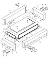
図1は、本発明の方法により製造する繊維強化複合体の一例を示す。このパネル状の繊維強化複合体1は、強化繊維にマトリックス樹脂を含浸したプリプレグを硬化させてなり、矩形状の平板部10と、その横手方向両側縁部から片側に突出したフランジ部11,11と、平板部10の長手方向両側縁部から両側に突出したフランジ部12,12と、平板部10に設けられた軽量化のための円孔13,13と、平板部10の四隅に設けられた円弧状の切り欠き部14とを有する。パネル状繊維強化複合体1の平板部10、フランジ部11,11及びフランジ部12の一方には、リベット等の接合部材により他の部材と接合するための孔15が設けられている。以下図1に示すパネル状繊維強化複合体1を成形する方法を例にとり、本発明の繊維強化複合体の製造方法を説明する。
[1] Manufacturing Method of Fiber Reinforced Composite FIG. 1 shows an example of a fiber reinforced composite manufactured by the method of the present invention. This panel-like fiber reinforced
(1) 成形型
(a) 形状
図2〜4は、図1に示すパネル状繊維強化複合体1を成形する型の一例を示す。この成形型は、繊維強化複合体1の平板部10及びフランジ部11,11,12,12を形成するキャビティ20,30を有する上型及び下型2,3と、上型及び下型2,3と密着する側型4,4,5,5とを有する。
(1) Mold
(a) Shape FIGS. 2-4 shows an example of the type | mold which shape | molds the panel-like fiber reinforced
上型2のキャビティ20は、繊維強化複合体1の平板部10を形成する水平部20aと、繊維強化複合体1のフランジ部12,12を形成する垂直部20b,20bとを有する。水平部20aの四隅には扇状凸部23a,23a,23a,23aが円弧部を内側にして設けられており、各扇状凸部23aの平坦な側面は垂直部20b,20bより僅かに外側に張り出している。各垂直部20bは上型2の厚さ方向途中まで延びているので、隣接する扇状凸部23aの根元部(上部)は上型2の上面に沿った水平凸部23cにより連結している。キャビティ20の外周に沿って樹脂漏れ防止用シール66を収容する溝21aが形成されているので、キャビティ20の外周縁と溝21aとの間がフランジ部22aとなる。
The
水平部20aの中央に、繊維強化複合体1の円孔13,13を設けるための一対の円状凸部23b,23bが設けられている。各円状凸部23bの中心部には、後述するピン65を挿入する孔25が設けられている。各円状凸部23bとその外周に設けられた同じ高さの環状フランジ部22bとの間に、樹脂漏れ防止用シール66を収容する環状溝21bが設けられている。
In the center of the
上型2には、繊維強化複合体1の孔15を設けるためにドリルを挿入する孔24が設けられている。図3(a) に示すように、孔24は、上側からネジ山を有する大径部24aと、ネジ山を有さない小径孔部24bとを有する。上型2用の樹脂漏れ防止プラグ62は孔24と相補的な形状を有し、大径孔部24aに螺合するネジ山付きの頭部62aを有する。小径孔部24bに挿入される先端部62bにはOリング(例えばシリコーンゴム、含フッ素ゴム等からなる)62cが装着されているので、樹脂漏れを防ぐことができる。プラグ62を孔24に螺入すると、小径孔部24bの先端面はキャビティ20の水平部20aと同一平面となる。
The
図4(a)に示すように、成形した繊維強化複合体1を上型2から取り外すために、上型2のフランジ部22aの内側面(キャビティ20の端面20c)にマイナスドライバ等の平坦な工具を差し入れる浅い溝26が適宜設けられている。
As shown in FIG. 4 (a), in order to remove the molded fiber-reinforced
下型3は上型2に対応する形状を有する。下型3のキャビティ30は、繊維強化複合体1の平板部10を形成する水平部30aと、繊維強化複合体1の短手方向フランジ部11,11を形成する垂直部30b,30bと、繊維強化複合体1の長手方向フランジ部12,12を形成する垂直部30c,30cとを有する。水平部30aの四隅には、上型2の扇状凸部23a,23a,23a,23aと同じ形状の扇状凸部33a,33a,33a,33aが設けられており、各扇状凸部33aの平坦な側面は垂直部30b,30b,30c,30cより僅かに外側に張り出している。各垂直部30b,30cは下型2の厚さ方向途中まで延びているので、隣接する扇状凸部33aの根元部(下部)は下型3の下面に沿った水平凸部33cにより連結している。キャビティ30の外周に沿って樹脂漏れ防止用シール66を収容する溝31aが形成されているので、キャビティ30の外周縁と溝31aとの間がフランジ部32aとなる。
The
水平部30aの中央に、繊維強化複合体1の円孔13,13を設けるための一対の円状凸部33b,33bが設けられている。各円状凸部33bとその外周に設けられた同じ高さの環状フランジ部32bとの間に、樹脂漏れ防止用シール66を収容する環状溝31bが設けられている。各円状凸部33bの中心部には、ピン65を挿入する孔37が設けられている。ピン65は孔37より大きい径の頭部65aを有するので、各ピン65を孔37に挿入すると、頭部65aは孔37に入らずに上型2の孔25に入る。その結果、下型3に対する上型2の位置が決まる。
A pair of circular
下型3は、水平部30aに上型2の孔24と垂直方向に整合した孔34を有し、一方の垂直部30b及び両方の垂直部30c,30cに孔34'を有する。孔34,34'は同じ径を有し、繊維強化複合体1の孔15を設けるためのドリルが入る。図3(b)に示すように、孔34は上側から小径部34a及び大径部34bを有する。下型3用の樹脂漏れ防止プラグ63は、小径孔部34aに密着する小径部63aと、大径孔部34bに入る大径部63bとからなる。図示していないが、必要に応じて成型中のプラグ63の脱落を防止するために大径部63bを大径孔部34bに螺合しても良い。孔34,34'に装着されたプラグ63の先端面はキャビティ30の水平部30a又は垂直部30b,30cと同一平面にある。下型3の下面には、マトリックス樹脂の硬化後にプラグ63を孔34'から抜くための溝38がキャビティ30の垂直部30b,30cに沿って設けられている。
The
図4(b)に示すように、下型3のフランジ部32aの内側面(キャビティ30の端面30d)にも、成形した繊維強化複合体1を下型3から取り外す平坦な工具を差し入れる浅い溝36が設けられている。
As shown in FIG. 4B, a shallow tool for removing the molded fiber-reinforced
硬化した繊維強化複合体1は型開き後に約0.1 mmだけ厚くなる傾向があるので、上型2及び下型3キャビティ20,30により形成されるキャビティを予め約0.1 mmだけ薄くしておくのが好ましい。
Since the cured fiber reinforced
(b) 材料
上型2及び下型3を構成する材料としては、例えば鋳鉄、鋼鉄(例えばJIS SS400等)、炭素鋼(例えばJIS S45C-H等)等が挙げられる。鋳鉄としては、株式会社榎本鋳工所から「ノビナイト」の商品名で市販されている低線膨張係数を有するものが好ましい。側型4,5を構成する材料としては、例えばアルミニウム等が挙げられる。
(b) Material Examples of the material constituting the
プラグ62,63,ピン65の材料としては、合金鋼(例えばJIS SCM435H等)が挙げられる。シール66の材料としては、硬化温度に耐える耐熱性を有するゴムであり、例えばポリテトラフロロエチレン(PTFE)等の含フッ素ゴム、シリコーンゴム等が挙げられる。PTFE製シールの市販品として、GORE-TEX No.3300(ジャパンゴアテックス株式会社製)が挙げられる。
Examples of the material of the
(2) 製造工程
(a) プリプレグ積層工程
予め上型2の孔24、及び下型3の孔34,34'に、樹脂漏れ防止プラグ62、63を挿入する。四隅を扇形に切り欠いた複数の矩形状布状プリプレグを、上型2及び下型3上に積層する。図5(a)及び図5(b)に示すように、上型2及び下型3上のプリプレグ積層体1a,1bはそれぞれ余肉を有する。
(2) Manufacturing process
(a) Prepreg Lamination Step Resin leakage prevention plugs 62 and 63 are inserted into the
布状プリプレグは強化繊維からなる布に、マトリックス樹脂を含浸させてなる。強化繊維としては特に制限されず、炭素繊維、アラミド繊維、ガラス繊維、ボロン繊維等から用途に応じて適宜選択される。マトリックス樹脂としては、熱硬化性樹脂が好ましく、エポキシ樹脂、ポリウレタン、不飽和ポリエステル、ビスマレイミド樹脂、フェノール樹脂等から用途に応じて適宜選択される。パネル状繊維強化複合体1を航空機胴体用部材として使用する場合、強化繊維としては炭素繊維が好ましく、マトリックス樹脂としてはエポキシ樹脂が好ましい。
The cloth-like prepreg is obtained by impregnating a matrix resin into a cloth made of reinforcing fibers. The reinforcing fiber is not particularly limited and is appropriately selected from carbon fiber, aramid fiber, glass fiber, boron fiber, and the like according to the use. The matrix resin is preferably a thermosetting resin, and is appropriately selected from an epoxy resin, a polyurethane, an unsaturated polyester, a bismaleimide resin, a phenol resin, and the like according to applications. When the panel-like fiber reinforced
(b) 余肉切除工程
図5(c)及び図5(d)に示すように、カッター等のトリミング工具72により、上型2のキャビティ20の端面20cに沿ってプリプレグ積層体1aの余肉12aを切除(トリミング)し、下型3のキャビティ30の端面30dに沿ってプリプレグ積層体1bの余肉11b,12bを切除する。上型2の溝21a,21b、及び下型3の溝31a,31bにシール66を装着する。上型2の溝26、及び下型3の溝36にシリコーンシートを詰める。下型3の孔37にピン65を挿入し、それらの頭部65aを上型2の孔25に挿入し、図5(f)に示すように、プリプレグ積層体1a,1bが接するように下型3に上型2を載置する。図5(f)及び図5(g)に示すように、上型2に載置したプリプレグ積層体1aを下型3に載置したプリプレグ積層体1bの上に垂らした状態で、下型3のキャビティ30の端面30dに沿って、プリプレグ積層体1aの長手方向余肉11aを切除する。トリミングは通常室温で行う。
(b) Surplus cutting process As shown in FIGS. 5 (c) and 5 (d), the surplus of the prepreg laminate 1a is made along the
本発明ではトリミングの容易な未硬化のプリプレグ積層体1a,1bから余肉を切除するので、硬化プリプレグ成形体をトリミングする従来の方法に比べて、良好な切断面を有する繊維強化複合体を簡便に製造できる。
In the present invention, surplus cuts are cut from the
(c) フランジ部用プリプレグの積層工程
図5(h)及び図5(i)に示すように、フランジ部12,12を強化するために、帯状プリプレグ1cを、強化繊維及びマトリックス樹脂からなる充填材1dを介して、プリプレグ積層体1a,1bのフランジ部12a,12bに積層する。このようにしてプリプレグ積層体1a,1b、帯状プリプレグ1c及び充填材1dを一体化したプリプレグ組立体1''が得られる。
(c) Flange prepreg laminating step As shown in FIGS. 5 (h) and 5 (i), in order to reinforce the
(d) 硬化工程
図6に示すように、組合せた上型2及び下型3の側面に側型4,4,5,5を付着し、プリプレグ組立体1''のフランジ部を支持する。図7に示すように、型全体を基盤80上に載置し、バッグフィルム81で被覆する。バッグフィルム81内を真空ポンプに接続した管82より減圧する。真空状態を保持できるように、バッグフィルム81を基盤80の上面に接着テープ83により密着する。
(d) Curing Step As shown in FIG. 6, the
バッグフィルム81内を真空状態に保持したまま加熱し(図8参照)、マトリックス樹脂を硬化させる。加熱はオーブン等の中で行うことができるが、オートクレーブ中で加圧しながら行うのが好ましい。加熱温度は、熱硬化性樹脂の種類によって若干異なるが、120〜180℃が好ましい。オートクレーブを使用する場合、3〜6MPa程度に加圧するのが好ましい。
The
(e) 穿孔工程
室温まで冷却した後、側型4,4,5,5を取り外し、図9に示すように、ショルダーボルト64を、板状の穿孔用治具6,6,7,7の孔61,71を介して、孔35に螺入することにより、板状穿孔用治具6,6,7,7を下型3に取り付ける。穿孔用治具6,7には、型中の繊維強化複合体1の孔15を設けるために、穿孔工具を挿入する孔60,70が各々設けられている。穿孔用治具6,7はアルミニウム等により形成できる。ショルダーボルト64は合金鋼(例えばJIS SCM435H等)により形成できる。
(e) Drilling step After cooling to room temperature, the
型2,3の孔24,34,34'から樹脂漏れ防止プラグ62,63を抜く。図9に示すように、上型2及び穿孔用治具6,7の孔24、60,70に、孔67aを有する筒状のガイドプラグ67を挿入する。図10に示すように、ガイドプラグ67は、孔24の大径部24aに密着する大径部67b、及び孔24の小径孔部24bに密着する小径部67cを有する。治具6,7の孔60,70も、ネジ山を有さない以外、孔24と同形状を有するので、ガイドプラグ67が係合する。
The resin leakage prevention plugs 62, 63 are removed from the
図11に示すように、ガイドプラグ67の孔67aにNCドリル等の穿孔工具73を挿入して、プリプレグ組立体1''を硬化させてなる硬化プリプレグ成形体1'を穿孔する。穿孔により得られる繊維強化複合体1の孔15の精度を高めるために、ガイドプラグ67の孔67aの径を穿孔工具73の直径D超〜D+50μm以下とするのが好ましい。ガイドプラグ67を孔24,60,70中に固定し、硬化プリプレグ成形体1'を垂直に穿孔する。このように型2,3内に硬化プリプレグ成形体1'が保持された状態で、孔24,34,34',60,70を有する穿孔用治具6,7を利用して穿孔するので、接合用孔15を精確かつ効率よく形成することができる。
As shown in FIG. 11, a
(f) 脱型工程
得られた繊維強化複合体1から、型2,3及び穿孔用治具6,7を取り外す。図12に示すように、上型2の孔25にはネジ山が設けられている。ネジ山付き孔25にボルト74を螺入し、その先端でピン65の頭部65aを押すことにより、上型2と下型3を容易に分離することができる。上型2のフランジ部22aに設けた溝26に、マイナスドライバ等の平坦な工具75を差し入れ、上型2から繊維強化複合体1を分離する。図13に示すように、下型3のフランジ部32aに設けた溝36にも平坦な工具75を差し入れ、下型3から繊維強化複合体1を持ち上げ、分離する。
(f) Demolding process The
(3) その他の実施態様
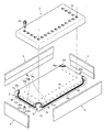
図14は本発明の方法により製造する繊維強化複合体の別の例を示す。このパネル状の繊維強化複合体1は、長手方向側縁部に設けられたフランジ部12,12が片側のみに突出しており、円孔13,13を有さない以外、図1に示す繊維強化複合体1と同じである。図15は、図14に示す繊維強化複合体1を成形する型の一例を示す。この成形型は、キャビティを有さない上型2と円状凸部33b等を有さない下型3とからなる以外、図2〜4に示す成形型と同じである。この型を用いた成形方法は本質的に上記と同じであるので、説明を省略する。
(3) Other Embodiments FIG. 14 shows another example of a fiber reinforced composite produced by the method of the present invention. This panel-like fiber reinforced
(4) 成形型の寸法設定
加熱硬化時の熱膨張による寸法精度の低下を防止するために、繊維強化複合体1(プリプレグ組立体1'',硬化プリプレグ成形体1')と成形型とはできるだけ近い線膨張係数を有するのが好ましい。具体的には、繊維強化複合体1に用いるCFRPの線膨張係数は約2.6×10⁻⁶/℃であるので、ノビナイトのグレードCS-5[線膨張係数:2.5×10-6/℃(200℃)]、又はCN-5[線膨張係数:2.7×10-6/℃(200℃)]を用いるのが好ましい。しかし、両者の線膨張係数の差が比較的大きい場合、硬化温度において硬化プリプレグ成形体1'と同じ寸法となるように、型2,3のキャビティの室温寸法を定めるのが好ましい。
(4) Mold size setting In order to prevent deterioration of dimensional accuracy due to thermal expansion during heat curing, fiber reinforced composite 1 (
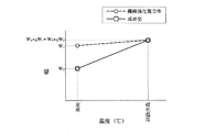
繊維強化複合体1のうち平板部10の寸法の精度が重要であるので、その設計長さをW1とし、その設計長さが得られるキャビティの長さをW2とする。室温から硬化温度に上昇すると、図16に示すように、平板部10の長さW1はW1+ΔW1(=α1・W1・ΔT)となり、キャビティの長さW2はW2+ΔW2(=α2・W2・ΔT)となる。ここで、α1は繊維強化複合体1の線膨張係数であり、α2は下型3の線膨張係数であり、ΔTは室温と硬化温度の差(℃)である。硬化温度では、平板部10の長さとキャビティの長さは同じになるので、W1+α1・W1・ΔT=W2+α2・W2・ΔTが成り立つ。従って、W2は下記式(1) により表される。
W2=W1×(1+α1・ΔT)/(1+α2・ΔT)・・・(1)
The accuracy of the dimensions of the
W 2 = W 1 × (1 + α 1 · ΔT) / (1 + α 2 · ΔT) (1)
繊維強化複合体1を型2,3から取り出すと、繊維強化複合体1の平板部10とフランジ部11の角度が僅かに減少する傾向があるため、減少分(例えば約0.5〜1.5°)だけキャビティ20,30の水平部20a,30aと垂直部30a,30bがなす角度を、最終製品における角度より大きくしておくのが好ましい。
When the fiber reinforced
[2] 胴体用構造体
以上のような製造方法により得られる繊維強化複合体は、軽量で強度が高いので、航空機胴体用構造体を構成する部材として好適である。図18は、本発明の方法により製造した繊維強化複合体を用いて航空機胴体用構造体を構成した例を示す。繊維強化複合体1はリベット90により接合されている。図18に示す構造体は、例えば航空機胴体の床用の構造体として使用することができる。この例では、繊維強化複合体1同士を接合しているが、これに限定されず、アルミニウム合金製部材等の他の部材と接合しても良い。図18に示す例では同じ形状の繊維強化複合体1を接合しているが、これに限定されず、異なる形状の繊維強化複合体1を組合せても良い。
[2] fuselage structure The fiber-reinforced composite obtained by the manufacturing method as described above is suitable as a member constituting the aircraft fuselage structure because it is lightweight and has high strength. FIG. 18 shows an example in which an aircraft fuselage structure is configured using a fiber reinforced composite produced by the method of the present invention. The fiber reinforced
1・・・繊維強化複合体
10・・・平板部
11,12・・・フランジ部
13・・・円孔
14・・・切り欠き部
15・・・孔
1a,1b・・・プリプレグ積層体
1c・・・帯状プリプレグ
1d・・・充填材
1'・・・硬化プリプレグ成形体
10'・・・平板部
11'・・・フランジ部
12'・・・フランジ部
1''・・・プリプレグ組立体
10''・・・平板部
11''・・・フランジ部
2・・・上型
20・・・キャビティ
20a・・・水平部
20b・・・垂直部
20c・・・端面
21a,21b・・・溝
22a・・・フランジ部
22b・・・環状フランジ部
23a・・・扇状凸部
23b・・・円状凸部
23c・・・水平凸部
24・・・孔
24a・・・大径部
24b・・・小径部
25・・・孔
26・・・溝
3・・・下型
30・・・キャビティ
30a・・・水平部
30b,30c・・・垂直部
30d・・・端面
31a,31b・・・溝
32a・・・フランジ部
32b・・・環状フランジ部
33a・・・扇状凸部
33b・・・円状凸部
33c・・・水平凸部
34・・・孔
34a・・・小径部
34b・・・大径部
34',35,37・・・孔
36・・・溝
38・・・溝
4・・・側型
5・・・側型
6・・・穿孔用治具
60,61・・・孔
7,7'・・・穿孔用治具
70,71・・・孔
62・・・樹脂漏れ防止用プラグ
62a・・・頭部
62b・・・先端部
62c・・・Oリング
63・・・樹脂漏れ防止用プラグ
64・・・ショルダーボルト
65・・・ピン
65a・・・頭部
66・・・樹脂漏れ防止用シール
67・・・ガイドプラグ
67a・・・孔
67b・・・大径部
67c・・・小径部
72・・・トリミング工具
73・・・穿孔工具
73a・・・ドリル刃
74・・・ボルト
75・・・平坦な工具
80・・・基盤
81・・・バッグフィルム
82・・・吸引管
83・・・接着テープ
90・・・リベット
1 ... Fiber-reinforced composite
10 ... flat plate
11, 12 ... Flange
13 ... Round hole
14 ... Notch
15 ... hole
1a, 1b ... Prepreg laminate
1c ・ ・ ・ Strip prepreg
1d ・ ・ ・ Filler
1 '・ ・ ・ Hardened prepreg molding
10 '... flat plate
11 '・ ・ ・ Flange part
12 '・ ・ ・ Flange part
1 '' ・ ・ ・ Prepreg assembly
10 '' ... flat plate
11 ”・ ・ ・ Flange
20 ... cavity
20a ・ ・ ・ Horizontal part
20b ・ ・ ・ Vertical part
20c ・ ・ ・ End face
21a, 21b ... groove
22a ・ ・ ・ Flange part
22b ・ ・ ・ Annular flange
23a ・ ・ ・ Fan convex
23b ・ ・ ・ Circular convex part
23c ・ ・ ・ Horizontal convex part
24 ... hole
24a ・ ・ ・ Large diameter part
24b ・ ・ ・ Small diameter part
25 ... hole
26 ...
30 ... cavity
30a ・ ・ ・ Horizontal part
30b, 30c ・ ・ ・ Vertical part
30d ・ ・ ・ End face
31a, 31b ... groove
32a ・ ・ ・ Flange part
32b ・ ・ ・ Annular flange
33a ... Fan-shaped convex part
33b ・ ・ ・ Circular convex part
33c ・ ・ ・ Horizontal convex part
34 ... hole
34a ・ ・ ・ Small diameter part
34b ・ ・ ・ large diameter part
34 ', 35, 37 ... holes
36 ・ ・ ・ Groove
38 ...
60, 61 ...
70, 71 ... hole
62 ... Plug for preventing resin leakage
62a ・ ・ ・ Head
62b ・ ・ ・ Tip
62c ・ ・ ・ O-ring
63 ... Resin leakage prevention plug
64 ... shoulder bolt
65 ・ ・ ・ Pin
65a ・ ・ ・ Head
66 ・ ・ ・ Seal for preventing resin leakage
67 ... Guide plug
67a ... hole
67b ・ ・ ・ large diameter part
67c ・ ・ ・ Small diameter part
72 ・ ・ ・ Trimming tool
73 ... Drilling tool
73a ... Drill blade
74 ... Bolt
75 ・ ・ ・ Flat tool
80 ・ ・ ・ Base
81 ... Bag film
82 ... Suction tube
83 ・ ・ ・ Adhesive tape
90 ... Rivets
Claims (1)
Priority Applications (1)
| Application Number | Priority Date | Filing Date | Title |
|---|---|---|---|
| JP2007153296A JP4825732B2 (en) | 2006-06-09 | 2007-06-08 | Method for producing fiber reinforced composite |
Applications Claiming Priority (3)
| Application Number | Priority Date | Filing Date | Title |
|---|---|---|---|
| JP2006161050 | 2006-06-09 | ||
| JP2006161050 | 2006-06-09 | ||
| JP2007153296A JP4825732B2 (en) | 2006-06-09 | 2007-06-08 | Method for producing fiber reinforced composite |
Publications (2)
| Publication Number | Publication Date |
|---|---|
| JP2008012920A JP2008012920A (en) | 2008-01-24 |
| JP4825732B2 true JP4825732B2 (en) | 2011-11-30 |
Family
ID=39070403
Family Applications (1)
| Application Number | Title | Priority Date | Filing Date |
|---|---|---|---|
| JP2007153296A Active JP4825732B2 (en) | 2006-06-09 | 2007-06-08 | Method for producing fiber reinforced composite |
Country Status (1)
| Country | Link |
|---|---|
| JP (1) | JP4825732B2 (en) |
Families Citing this family (1)
| Publication number | Priority date | Publication date | Assignee | Title |
|---|---|---|---|---|
| GB0614087D0 (en) * | 2006-07-14 | 2006-08-23 | Airbus Uk Ltd | Composite manufacturing method |
Family Cites Families (11)
| Publication number | Priority date | Publication date | Assignee | Title |
|---|---|---|---|---|
| US4160005A (en) * | 1977-11-07 | 1979-07-03 | United Technologies Corporation | Method of fabricating a selectively shaped and apertured part of fiber reinforced plastic |
| JPS598537B2 (en) * | 1981-02-18 | 1984-02-25 | 日本発条株式会社 | Hole processing method for FRP molded body |
| JPH01272440A (en) * | 1988-04-26 | 1989-10-31 | Fuji Heavy Ind Ltd | Mold for composite material molded product |
| JP2740218B2 (en) * | 1988-12-27 | 1998-04-15 | 富士重工業株式会社 | Manufacturing method for composite products |
| JP2730946B2 (en) * | 1989-01-10 | 1998-03-25 | 富士重工業株式会社 | Composite material molding method |
| JPH07195376A (en) * | 1993-12-28 | 1995-08-01 | Honda Motor Co Ltd | Mold for fiber reinforced plastic, master mold and production of them |
| JP3483623B2 (en) * | 1994-07-19 | 2004-01-06 | 富士重工業株式会社 | Method of molding fiber reinforced plastic structural member |
| JP2001269946A (en) * | 2000-03-23 | 2001-10-02 | Mitsui Chemicals Inc | Manufacturing method of photo-setting resin board |
| JP4484356B2 (en) * | 2000-12-11 | 2010-06-16 | 大日本印刷株式会社 | Lamination body peeling method and peeling apparatus |
| JP4327421B2 (en) * | 2002-08-02 | 2009-09-09 | ドゥケーヌ バンサン | Method for molding parts made from synthetic material and apparatus enabling the method |
| JP4635631B2 (en) * | 2005-02-03 | 2011-02-23 | 株式会社ニコン | Optical element manufacturing method |
-
2007
- 2007-06-08 JP JP2007153296A patent/JP4825732B2/en active Active
Also Published As
| Publication number | Publication date |
|---|---|
| JP2008012920A (en) | 2008-01-24 |
Similar Documents
| Publication | Publication Date | Title |
|---|---|---|
| JP5111068B2 (en) | Method for producing perforated fiber reinforced composite | |
| US20080072527A1 (en) | Fiber-reinforced composite member and method for producing structure using same | |
| Türk et al. | Composites part production with additive manufacturing technologies | |
| US7510757B2 (en) | Cellular composite grid-stiffened structure | |
| KR102197337B1 (en) | Composite structure having a stabilizing element | |
| US4696711A (en) | Method for forming holes in composites | |
| RU2492046C2 (en) | Method of making component of fibrous composite for aircraft and space engineering | |
| KR101834981B1 (en) | Module for holding at least one bushing | |
| JP5628671B2 (en) | Composite laminated structure | |
| CA2831084C (en) | Method of repairing, splicing, joining, machining, and stabilizing honeycomb core using pourable structural foam and a structure incorporating the same | |
| US7943075B2 (en) | Method for producing fiber-reinforced composite | |
| KR102588159B1 (en) | Textured caul plate and method of use | |
| US10232569B2 (en) | Device and method for manufacturing fiber-reinforced plastic structure | |
| RU2633094C2 (en) | Method for manufacturing plastic parts/constructive parts of vehicle | |
| US6841021B1 (en) | Method of making a polyimide resin and carbon fiber molded tube clamp | |
| US7138031B2 (en) | Mandrel and method for manufacturing composite structures | |
| CA2831097A1 (en) | Method of repairing, splicing, joining, machining, and stabilizing honeycomb core using pourable structural foam and a structure incorporating the same | |
| JP4825732B2 (en) | Method for producing fiber reinforced composite | |
| EP3453525B1 (en) | Method and apparatus for manufacturing stiffened composite sandwich panels | |
| JP2009126056A (en) | Fiber-reinforced composite material | |
| CN115196037A (en) | Method for repairing composite materials using a pre-cured plug | |
| US10899084B2 (en) | Methods for forming composite structures | |
| CA2831103C (en) | Method of repairing, splicing, joining, machining, and stabilizing honeycomb core using pourable structural foam and a structure incorporating the same | |
| CA2831098C (en) | Method of repairing, splicing, joining, machining, and stabilizing honeycomb core using pourable structural foam and a structure incorporating the same | |
| US11554561B2 (en) | Integrally stiffened bonded panel with machined pockets and methods of manufacture |
Legal Events
| Date | Code | Title | Description |
|---|---|---|---|
| A621 | Written request for application examination |
Free format text: JAPANESE INTERMEDIATE CODE: A621 Effective date: 20091126 |
|
| A977 | Report on retrieval |
Free format text: JAPANESE INTERMEDIATE CODE: A971007 Effective date: 20110427 |
|
| A131 | Notification of reasons for refusal |
Free format text: JAPANESE INTERMEDIATE CODE: A131 Effective date: 20110601 |
|
| A521 | Request for written amendment filed |
Free format text: JAPANESE INTERMEDIATE CODE: A523 Effective date: 20110727 |
|
| TRDD | Decision of grant or rejection written | ||
| A01 | Written decision to grant a patent or to grant a registration (utility model) |
Free format text: JAPANESE INTERMEDIATE CODE: A01 Effective date: 20110817 |
|
| A01 | Written decision to grant a patent or to grant a registration (utility model) |
Free format text: JAPANESE INTERMEDIATE CODE: A01 |
|
| A61 | First payment of annual fees (during grant procedure) |
Free format text: JAPANESE INTERMEDIATE CODE: A61 Effective date: 20110912 |
|
| R150 | Certificate of patent or registration of utility model |
Ref document number: 4825732 Country of ref document: JP Free format text: JAPANESE INTERMEDIATE CODE: R150 Free format text: JAPANESE INTERMEDIATE CODE: R150 |
|
| FPAY | Renewal fee payment (event date is renewal date of database) |
Free format text: PAYMENT UNTIL: 20140916 Year of fee payment: 3 |
|
| FPAY | Renewal fee payment (event date is renewal date of database) |
Free format text: PAYMENT UNTIL: 20140916 Year of fee payment: 3 |
|
| S111 | Request for change of ownership or part of ownership |
Free format text: JAPANESE INTERMEDIATE CODE: R313113 |
|
| FPAY | Renewal fee payment (event date is renewal date of database) |
Free format text: PAYMENT UNTIL: 20140916 Year of fee payment: 3 |
|
| R350 | Written notification of registration of transfer |
Free format text: JAPANESE INTERMEDIATE CODE: R350 |
|
| R250 | Receipt of annual fees |
Free format text: JAPANESE INTERMEDIATE CODE: R250 |
|
| R250 | Receipt of annual fees |
Free format text: JAPANESE INTERMEDIATE CODE: R250 |
|
| R250 | Receipt of annual fees |
Free format text: JAPANESE INTERMEDIATE CODE: R250 |
|
| R250 | Receipt of annual fees |
Free format text: JAPANESE INTERMEDIATE CODE: R250 |
|
| R250 | Receipt of annual fees |
Free format text: JAPANESE INTERMEDIATE CODE: R250 |
|
| R250 | Receipt of annual fees |
Free format text: JAPANESE INTERMEDIATE CODE: R250 |
|
| R250 | Receipt of annual fees |
Free format text: JAPANESE INTERMEDIATE CODE: R250 |
|
| R250 | Receipt of annual fees |
Free format text: JAPANESE INTERMEDIATE CODE: R250 |
|
| R250 | Receipt of annual fees |
Free format text: JAPANESE INTERMEDIATE CODE: R250 |