JP4811246B2 - Capacitor - Google Patents
Capacitor Download PDFInfo
- Publication number
- JP4811246B2 JP4811246B2 JP2006319852A JP2006319852A JP4811246B2 JP 4811246 B2 JP4811246 B2 JP 4811246B2 JP 2006319852 A JP2006319852 A JP 2006319852A JP 2006319852 A JP2006319852 A JP 2006319852A JP 4811246 B2 JP4811246 B2 JP 4811246B2
- Authority
- JP
- Japan
- Prior art keywords
- metal cap
- round bar
- lead wire
- external terminal
- aluminum
- Prior art date
- Legal status (The legal status is an assumption and is not a legal conclusion. Google has not performed a legal analysis and makes no representation as to the accuracy of the status listed.)
- Expired - Fee Related
Links
Images


Classifications
-
- H—ELECTRICITY
- H01—ELECTRIC ELEMENTS
- H01G—CAPACITORS; CAPACITORS, RECTIFIERS, DETECTORS, SWITCHING DEVICES OR LIGHT-SENSITIVE DEVICES, OF THE ELECTROLYTIC TYPE
- H01G9/00—Electrolytic capacitors, rectifiers, detectors, switching devices, light-sensitive or temperature-sensitive devices; Processes of their manufacture
- H01G9/004—Details
- H01G9/008—Terminals
-
- H—ELECTRICITY
- H01—ELECTRIC ELEMENTS
- H01G—CAPACITORS; CAPACITORS, RECTIFIERS, DETECTORS, SWITCHING DEVICES OR LIGHT-SENSITIVE DEVICES, OF THE ELECTROLYTIC TYPE
- H01G9/00—Electrolytic capacitors, rectifiers, detectors, switching devices, light-sensitive or temperature-sensitive devices; Processes of their manufacture
- H01G9/004—Details
- H01G9/08—Housing; Encapsulation
- H01G9/10—Sealing, e.g. of lead-in wires
-
- H—ELECTRICITY
- H01—ELECTRIC ELEMENTS
- H01G—CAPACITORS; CAPACITORS, RECTIFIERS, DETECTORS, SWITCHING DEVICES OR LIGHT-SENSITIVE DEVICES, OF THE ELECTROLYTIC TYPE
- H01G9/00—Electrolytic capacitors, rectifiers, detectors, switching devices, light-sensitive or temperature-sensitive devices; Processes of their manufacture
- H01G9/15—Solid electrolytic capacitors
- H01G9/151—Solid electrolytic capacitors with wound foil electrodes
Description
本発明は、コンデンサに関するもので、特にリード線を挿通する貫通孔を備えた封口体を有するコンデンサに関する。 The present invention relates to a capacitor , and more particularly to a capacitor having a sealing body provided with a through hole through which a lead wire is inserted.
図11は、従来の電解コンデンサの断面図である。 FIG. 11 is a cross-sectional view of a conventional electrolytic capacitor.
従来の電解コンデンサのリード線151は、図11に示すように、アルミ線丸棒152と、銅下地錫めっき鉄線(CP線)からなる外部端子154とを接合したものである。コンデンサ素子156は、リード線151をアルミニウム等の弁作用金属からなる陽極箔と陰極箔に夫々接合し、この陽極箔と陰極箔にセパレータを介在させて巻回したものである。
As shown in FIG. 11, a conventional electrolytic
外装ケース160は、有底円筒状のアルミニウムからなり、この外装ケース160に、コンデンサ素子156、駆動用電解液や導電性高分子からなる固体電解質等の電解質(図示せず)が収納される。
The
外装ケース160の開放端は、一対のリード線151が挿通する貫通孔162を備えたゴム弾性封口体161を用いて封止され、電解コンデンサとしたものである。
The open end of the
このような電解コンデンサに用いる従来のリード線の製造方法としては、アルミ線丸棒152と外部端子154の端部をアーク溶接により接合したものがある。またアルミ線丸棒152の端面に穴加工し、この穴内に外部端子154を挿入後、ガスバーナで加熱しアルミ線丸棒152と外部端子154を接合したものもある。
As a conventional lead wire manufacturing method used for such an electrolytic capacitor, there is a method in which an aluminum
なお、この出願の発明に関連する先行技術文献情報としては、例えば特許文献1、特許文献2、特許文献3が知られている。
このような従来のアルミ線丸棒152と外部端子154のCP線をアーク溶接により直接接合する方法は、アルミ線丸棒152の径が小さくなり外部端子154との線径の相違が小さくなると、溶接条件の制御が難しく、アルミ線丸棒152、外部端子154が過剰に溶融し易くなり、接合部にバリや突起が生じる。
In the method of directly joining the conventional aluminum
このようなリード線のバリや突起により、リード線を封口体の貫通孔に挿入する時に貫通孔に擦り傷が生じ、これがリード線と封口体の隙間となって駆動用電解液が漏れやすくなり電解コンデンサの信頼性が低下するという課題があった。 Such lead wire burrs and protrusions cause scratches in the through-hole when the lead wire is inserted into the through-hole of the sealing body, and this leads to a gap between the lead wire and the sealing body, so that the drive electrolyte can easily leak. There was a problem that the reliability of the capacitor was lowered.
本発明は、このような従来の課題を解決し、接合部のバリや突起の発生を抑制することによりコンデンサの信頼性を向上させることを目的とする。 An object of the present invention is to solve such a conventional problem and to improve the reliability of a capacitor by suppressing the occurrence of burrs and protrusions at a joint.
上記目的を達成するために、本発明は、アルミ線丸棒の端部に断面凹形の金属キャップが嵌合された構成としたものである。 In order to achieve the above object, the present invention has a configuration in which a metal cap having a concave cross section is fitted to an end of an aluminum wire round bar.
また、本発明のリード線の製造方法は、断面凹形の金属キャップをアルミ線丸棒の端部に嵌め込む嵌込み工程と、前記金属キャップの開口部に対向する端部の外面と外部端子とを溶接する溶接工程と、を含む構成としたものである。 The lead wire manufacturing method of the present invention includes a fitting step of fitting a metal cap having a concave cross section into an end of an aluminum wire round bar, an outer surface of the end facing the opening of the metal cap, and an external terminal. And a welding process for welding.
以上のように本発明のリード線、及びリード線の製造方法よれば、外部端子は、直接金属キャップと溶接することによって、外部端子と接合する金属の選択が容易にできるため、金属キャップと外部端子を接合する溶接条件が制御しやすい金属にすることができ、外部端子と金属キャップとの接合強度を保ちながら金属キャップの表面にバリ等の不良形状の発生を抑制することができる。 As described above, according to the lead wire and the lead wire manufacturing method of the present invention, the external terminal can be easily selected by selecting the metal to be joined to the external terminal by welding directly to the metal cap. The welding conditions for joining the terminals can be easily controlled metal, and the occurrence of defective shapes such as burrs on the surface of the metal cap can be suppressed while maintaining the joining strength between the external terminal and the metal cap.
さらに、アルミ線丸棒は、金属キャップに嵌め込まれることによって、金属キャップとアルミ線丸棒の端部との接合面は金属キャップに被覆されるため、この接合面の接合状態による、アルミ線丸棒と外部端子との接合部の外観形状への悪影響を低減でき、バリ等の不良形状の発生を抑制することができる。 Furthermore, since the aluminum wire round bar is fitted into the metal cap, the joint surface between the metal cap and the end of the aluminum wire round bar is covered with the metal cap. The adverse effect on the external shape of the joint portion between the rod and the external terminal can be reduced, and the occurrence of defective shapes such as burrs can be suppressed.
(実施の形態1)
まず、本発明のリード線の製造方法について説明する。
(Embodiment 1)
First, the manufacturing method of the lead wire of this invention is demonstrated.
図3は、本発明のリード線の接合方法を示す工程斜視図であり、断面凹形の金属キャップを用いて、金属キャップをアルミ線丸棒の端部に嵌め込む嵌込み工程、金属キャップの開口部に対向する端部の外面と外部端子とを溶接する溶接工程を順次行うものである。 FIG. 3 is a process perspective view showing a method for joining lead wires according to the present invention, and using a metal cap having a concave cross section, a fitting step of fitting a metal cap into an end of an aluminum wire round bar, A welding process of sequentially welding the outer surface of the end facing the opening and the external terminal is performed.
図3(a)は初期状態を示し、金属キャップ3は、金属板をプレス加工することによって、開口部3bと、開口部3bに対向するドーム状の端部3aとを備え、開口部3bと端部3aとを結ぶ軸方向に沿った断面が凹形としたものである。
FIG. 3A shows an initial state, and the
外部端子4は、鉄、ニッケル、銅の単体、鉄合金、ニッケル合金、銅合金などからなる金属基材の線または板である。また、外部端子4は、めっき層が形成されてもよく、めっき層として、例えば回路基板との接続のためにSn単体、あるいはSnにAg、Bi、In、Pbなどが添加された錫合金からなる錫系めっきを用いることができる。
The
次に図3(b)に示すように、アルミ線丸棒2の端部は、金属キャップ3の内周に係合するようにプレス加工、またはガラ掛け研磨等によりトリミングした後、図3(c)に示すように、金属キャップ3をアルミ線丸棒2の端部に嵌め込む。
Next, as shown in FIG. 3 (b), the end portion of the aluminum
図3(d)において、溶接用の電極を外部端子4とアルミ線丸棒2に夫々接続し、アーク溶接、抵抗溶接等の電気溶接を用いて、外部端子4と金属キャップ3との接合を行い、アルミ線丸棒2は金属キャップ3内面と接合され、外部端子4は外面端部3aと接合され、リード線1とした。
In FIG. 3D, welding electrodes are connected to the
また、金属キャップ3は、金属キャップ3と外部端子4とを抵抗溶接によって接合する場合、金属キャップ3と外部端子4との電気抵抗の相違が小さいことが好ましく、例えば外部端子4が鉄系基材の場合は、金属キャップ3は鉄、ニッケル、鉄ニッケル合金系基材を選択し、外部端子4が銅系基材の場合は、金属キャップ3は銅、銅合金基材を選択することが望ましく、これによって外部端子4と金属キャップ3との接合強度を保ちながら、
バリ等の形状不良発生を抑制する効果を高めることができる。
The
The effect of suppressing occurrence of shape defects such as burrs can be enhanced.
また、金属キャップ3と外部端子4とが抵抗溶接等により接合する際に、金属キャップ3とアルミ線丸棒2の端部との接合部に溶融が生じても、金属キャップ3に被覆されるため、金属キャップ3と外部端子4との接合部において溶融のバリ等の不良形状の発生がないものとすることができる。
Further, when the
また、金属キャップ3の端部3aの外面は、平坦状であってもよく、これによって外部端子4との接合状態を安定にすることができる。
Further, the outer surface of the end portion 3a of the
なお、図3では、金属キャップ3の外形径は、アルミ線丸棒2の直径より大きいものであるが、アルミ線丸棒2の直径と同一あるいは小さくてもよい。例えば、アルミ線丸棒の先端をトリミングして細くし、アルミ線丸棒2の径より小さい外径の金属キャップを嵌合してもよいし、また、アルミ線丸棒の、金属キャップとの接合部のみ径を細くしてもよい。
In FIG. 3, the outer diameter of the
リード線1の製造方法は、溶接工程は、嵌込み工程より前に行われてもよい。 In the method for manufacturing the lead wire 1, the welding process may be performed before the fitting process.
(実施の形態2)
本発明の実施の形態2は、実施の形態1におけるリード線の製造工程に新たな工程を追加した以外は、実施の形態1と同様であるため、同一部分には同一の符号を付与してその詳細な説明は省略し、異なる部分についてのみ以下に図面を用いて説明する。
(Embodiment 2)
Since the second embodiment of the present invention is the same as the first embodiment except that a new process is added to the lead wire manufacturing process of the first embodiment, the same reference numerals are given to the same parts. Detailed description thereof will be omitted, and only different parts will be described below with reference to the drawings.
実施の形態2におけるリード線の製造方法は、金属キャップ3をアルミ線丸棒2の端部に嵌め込む嵌込み工程の後、金属キャップ3とアルミ線丸棒2とを加熱処理により接合する接合工程を含む製造方法である。
In the lead wire manufacturing method according to the second embodiment, the
金属キャップ3の端部3aと外部端子4とを溶接する溶接工程は、接合工程の前または後で行うことができる。
The welding process for welding the end 3a of the
接合工程は、金属キャップ3を、ガスバーナにより金属キャップ3の外面から加熱処理する。加熱処理は、抵抗加熱、レーザ、電磁誘導による方法を用いてもよい。
In the joining step, the
この加熱処理により、アルミ線丸棒2と金属キャップ3間に合金拡散層が形成され、接合強度が向上する。加熱処理によって接合するため、金属キャップ3の厚みを調整することによって、金属キャップ3が過剰に溶融することで発生する形状不良を防止しながら接合強度を向上することができる。
By this heat treatment, an alloy diffusion layer is formed between the
また、金属キャップ3が、アルミ線丸棒2の端部を被覆する範囲を調整することによって、アルミ線丸棒2と金属キャップ3との接合部で溶融した金属を金属キャップ3に収納することが容易にでき、金属キャップ3と外部端子4との接合部においてバリ等の突起状の形状不良の発生を防止できる。
Further, by adjusting the range in which the
また、金属キャップ3は、アルミニウムより融点の高い金属の基材から構成されることが好ましく、この金属キャップ3は、合金拡散層が加熱処理によってアルミ線丸棒2に比較し過剰に溶融されて形状不良となることを防ぐ効果を奏するものである。
The
また、アルミニウムより融点の高い金属としては、銅、ニッケル、鉄の金属単体、銅、ニッケル、鉄を含有する合金等から構成されることが好ましく、これらの金属はアルミニウムの融点以下で液相状態の合金を生成することができるため、加熱処理によってアルミ線丸棒2と金属キャップ3間に合金拡散層が形成され易く、更に接合強度を向上する効果を奏するものである。またこれらの金属は、合金拡散層を形成され易くするために、金属キャップ3の内側に設けられることが好ましく、金属キャップ3の基材、またはめっき層を設けたものとしてもよい。
The metal having a higher melting point than aluminum is preferably composed of copper, nickel, iron simple substance, copper, nickel, an alloy containing iron, etc., and these metals are in a liquid phase state below the melting point of aluminum. Therefore, an alloy diffusion layer is easily formed between the aluminum
以上のリード線の製造方法によって、アルミ線丸棒2と外部端子4との接合強度を確保しながら、アルミ線丸棒2と外部端子4との接合部の形状不良の発生を抑制でき、接合状態を安定にすることができるという効果を奏するものである。
With the above lead wire manufacturing method, it is possible to suppress the occurrence of a shape defect in the joint portion between the aluminum
(実施の形態3)
次に、本発明のリード線を用いた電解コンデンサの構成について説明する。
(Embodiment 3)
Next, the structure of the electrolytic capacitor using the lead wire of the present invention will be described.
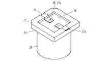
図1は、本発明のリード線を用いた電解コンデンサの構成を示した断面図、図2は、同リード線が接合されたコンデンサ素子の展開斜視図である。 FIG. 1 is a cross-sectional view showing a configuration of an electrolytic capacitor using the lead wire of the present invention, and FIG. 2 is a developed perspective view of a capacitor element to which the lead wire is joined.
本発明の電解コンデンサは、一対のリード線1を陽極箔、陰極箔にそれぞれ接続したコンデンサ素子6と、コンデンサ素子6を収納した有底筒状の外装ケース10と、リード線1を挿通する貫通孔12を備えるとともに前記外装ケース10の開放端を封止する封口体11とからなるものである。
The electrolytic capacitor of the present invention includes a
図2において、リード線1は、実施の形態1または実施の形態2の製造方法により、形成されたもので、アルミ線丸棒2が金属キャップ3に嵌め込まれ、外部端子4が金属キャップ3の端部の外面と接合されている。さらにアルミ線丸棒2の他方の端側には扁平に加工された平面部5を設けている。
In FIG. 2, the lead wire 1 is formed by the manufacturing method of the first embodiment or the second embodiment. The aluminum
リード線1の平面部5は、アルミニウム等の弁作用金属からなる陽極箔7、陰極箔8と超音波溶接あるいは圧接によって夫々接合される。さらに陽極箔7と陰極箔8とを、セパレータ9を介在させて巻回し、一対のリード線1が導出したコンデンサ素子6としたものである。
The flat portion 5 of the lead wire 1 is joined to the
外装ケース10は、アルミニウム、アルミニウム合金等の金属から構成され、外装ケース10には、コンデンサ素子6と、駆動用電解液、導電性高分子からなる固体電解質等の電解質(図示せず)とが収納されている。
The
外装ケース10の開放端は、弾性体からなる封口体11により封止され、封口体11の貫通孔12には、リード線1が挿通され、金属キャップ3は貫通孔12内面に当接し、外部端子4は、貫通孔12より突出し封口体11より露呈している。
The open end of the
なお、貫通孔12は、貫通孔12の径をアルミ線丸棒2の径と同じ、又は少し小さくすることによって、密閉されている。
The through hole 12 is sealed by making the diameter of the through hole 12 the same as or slightly smaller than the diameter of the aluminum
本発明のリード線1は、外部端子4からアルミ線丸棒2の順に、封口体11の貫通孔12に挿入する。この挿入の際に、アルミ線丸棒2と外部端子4との接合部に形状不良がないために、貫通孔12に擦り傷を生じにくくなり、リード線1と貫通孔12の隙間の発生を抑制することができる。これによって、駆動用電解液の漏れ等が発生しにくくなり、電解コンデンサの信頼性を向上することができる。
The lead wire 1 of the present invention is inserted into the through hole 12 of the sealing
また金属キャップ3の形状は、図1、図3に示すように、金属キャップ3の端部3a側から開口部3b側へ向かう方向に沿って、外径が拡大する曲面を金属キャップの外周全体または一部に有することが好ましく、例えばドーム状、円錐状、円錐台形状等であって、金属キャップ3は、リード線1が貫通孔12に挿入される際に、少なくとも貫通孔12内面と接触する部分が前記曲面を有するものであればよく、端部3aの外面の先端は、平坦状であってもよい。
As shown in FIGS. 1 and 3, the shape of the
このような曲面を有することによって、リード線1を封口体11の貫通孔12に挿入する際にリード線1に作用する負荷を低減することができる。これによって、リード線1が変形し、または一対のリード線1の挿入が相互にずれて、コンデンサ素子6の陽極箔7、陰極箔8が変形することを防止でき、電解コンデンサの漏れ電流特性が向上するという効果を奏するものである。
By having such a curved surface, it is possible to reduce a load acting on the lead wire 1 when the lead wire 1 is inserted into the through hole 12 of the sealing
また、リード線1は、図1に示すように、金属キャップ3の開口部3bが、封口体11の貫通孔12に挿入される部分のアルミ線丸棒2の線径より大きくなるように段差部13を設けたものでもよく、図1に示すように、段差部13は、金属キャップの材料厚みによって構成されている。また、この段差部13は、金属キャップ3の開口部3b側の外径をアルミ線丸棒2の径より大きくして前記開口部3b側の金属キャップ3端面に設けることもでき、その段差部は、例えば、階段状に複数の段差を有する段差部(図示せず)にしてもよい。
Further, as shown in FIG. 1, the lead wire 1 has a step so that the opening 3 b of the
段差部13を設けることによって、金属キャップ3とアルミ線丸棒2との段差部13が貫通孔12に強固に係合することができ、リード線1が外装ケース10内方向にずれてコンデンサ素子6の陽極箔7、陰極箔8が変形することを防止でき、電解コンデンサの漏れ電流特性が向上するという効果を奏するものである。
By providing the
(実施の形態4)
次に、本発明の他のリード線を用いた電解コンデンサについて説明する。
(Embodiment 4)
Next, an electrolytic capacitor using another lead wire of the present invention will be described.
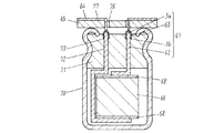
図4は、本発明の実施の形態4の電解コンデンサの構成を示した断面図、図5は、同下面斜視図、図6は、同コンデンサ素子の展開斜視図、図8は、本発明の他のリード線の接合方法を示す工程斜視図である。
4 is a cross-sectional view showing a configuration of an electrolytic capacitor according to
本発明のリード線は、アルミ線丸棒の端部に断面凹形の金属キャップが嵌合されたものである。 The lead wire of the present invention has a metal cap having a concave cross section fitted to the end of an aluminum wire round bar.
まず、本発明のリード線21の製造方法について、図8を用いて説明する。
First, the manufacturing method of the
図8(a)において、金属キャップ23は、金属板をプレス加工することによって、一方の端部に開口部23bと、他方の端部に平坦状に閉じた端部23aとを備えた円柱空洞の筒形状とし、開口部23bと端部23aとを結ぶ軸方向に沿った断面を凹形としたものである。
In FIG. 8A, a
次に、図8(b)に示すように、金属キャップ23をアルミ線丸棒22の端部に嵌め込んで、リード線21とした。
Next, as shown in FIG. 8B, the
また、アルミ線丸棒22の端部は、金属キャップ23の内周に係合するようにプレス加工、またはガラ掛け研磨等によりトリミングした後、金属キャップ23を嵌合させてもよい。
Further, the end portion of the aluminum
さらに、アルミ線丸棒22と金属キャップ23との嵌合部を加熱処理することにより、アルミ線丸棒22と金属キャップ23とを接合してもよい。
Furthermore, you may join the aluminum
この加熱処理は、金属キャップ23を、ガスバーナにより金属キャップ23の外面から加熱することにより行うことができ、加熱処理により、アルミ線丸棒22と金属キャップ23間に合金拡散層が形成され、接合強度が向上するという効果を奏するものである。また加熱処理は、抵抗加熱、レーザ、電磁誘導による方法を用いてもよい。
This heat treatment can be performed by heating the
また、金属キャップ23は、アルミ線丸棒22の端部を被覆する範囲を調整することによって、アルミ線丸棒22と金属キャップ23との接合部で溶融した金属を金属キャップ23に収納することが容易にでき、バリ等の突起状の形状不良の発生を抑制できる。
Moreover, the
また、金属キャップ23は、金属キャップ23の厚みを調整することで、金属キャップ23の外面を過剰に溶融することなく接合部を溶融することができ、バリ等の突起状の形状不良の発生を防止できる。
Moreover, the
また、金属キャップ23の加熱処理される円柱側面、または端部23aの厚みは、接合部を均一に溶融させるために、均一であることが好ましい。
Moreover, it is preferable that the thickness of the cylindrical side surface of the
また、金属キャップ23は、アルミニウムより融点の高い金属の基材から構成されることが好ましく、この金属キャップ23は、合金拡散層が前記加熱処理によってアルミ線丸棒22の端部に比較し過剰に溶融されて形状不良となることを防ぐ効果を奏するものである。
The
アルミニウムより融点の高い金属としては、銅、ニッケル、鉄の金属単体、銅、ニッケル、鉄を含有する合金等から構成されることが好ましく、これらの金属はアルミニウムの融点以下で液相状態の合金を生成することができるため、加熱処理によってアルミ線丸棒22と金属キャップ23間に合金拡散層が形成され易く、更に接合強度を向上させる効果を奏するものである。またこれらの金属は、合金拡散層を形成され易くするために、金属キャップ23の内側に設けられることが好ましく、金属キャップ23の基材、またはめっき層として設けたものとしてもよい。
The metal having a melting point higher than that of aluminum is preferably composed of copper, nickel, iron simple substance, copper, nickel, iron-containing alloy, etc., and these metals are alloys in a liquid phase state below the melting point of aluminum. Therefore, an alloy diffusion layer is easily formed between the aluminum
次に、本発明のリード線を用いた実施の形態4の電解コンデンサについて説明する。
Next, the electrolytic capacitor of
図6において、リード線21には、金属キャップ23を嵌め込んだアルミ線丸棒22の端部に対し他方の端側には扁平に加工された平面部25を設けている。
In FIG. 6, the
リード線21の平面部25は、アルミニウム等の弁作用金属からなる陽極箔27、陰極箔28と超音波溶接あるいは圧接によって夫々接合される。さらに陽極箔27と陰極箔28とを、セパレータ29を介在させて巻回し、一対のリード線21が導出したコンデンサ素子36としたものである。
The
図4に示すように、外装ケース30は、アルミニウム、アルミニウム合金等の金属から構成され、外装ケース30には、コンデンサ素子36と、駆動用電解液、または導電性高分子からなる固体電解質等の電解質(図示せず)とが収納されている。
As shown in FIG. 4, the
外装ケース30の開放端は、封口体31により封止され、封口体31の貫通孔32には、リード線21が挿通され、金属キャップ23は、外装ケース30の開放端側の貫通孔32内面に当接しかつ貫通孔32より突出して封口体31より露呈している。
The open end of the
なお、貫通孔32は、貫通孔32の径をアルミ線丸棒22の径と同じ、又は少し小さくすることによって、密閉されている。
The through hole 32 is sealed by making the diameter of the through hole 32 the same as or slightly smaller than the diameter of the aluminum
さらに、外装ケース30の開放端には、当接した絶縁体34を備え、この絶縁体34の平坦状の底面37に沿って配置された一対の平板状の外部端子24が、絶縁体34に備えた貫通孔26を挿通して、露呈した金属キャップ23の端部の外面に接合されている。
Further, the open end of the
図5に示すように、絶縁体34の底面37に設けた溝37aに沿って収納された外部端子24は、絶縁体34の貫通孔26に挿通する方向に屈曲し、さらに絶縁体34の底面37と平行に屈曲して、金属キャップ23の端部23aに接合されたものである。
As shown in FIG. 5, the
また、外部端子24は、鉄、ニッケル、銅の単体、鉄合金、ニッケル合金、銅合金などからなるアルミニウムとは異なる金属基材からなる板または線である。また、外部端子24は、めっき層が形成されてもよく、めっき層として、例えば回路基板との接続のためにSn単体、あるいはSnにAg、Bi、In、Pbなどが添加された錫合金からなる錫系めっきを用いることができる。
The
また、絶縁体34は、ポリエチレン、ポリプロピレン、ポリエチレンテレフタレート、液晶ポリマー等の熱可塑性樹脂、またはフェノール樹脂、エポキシ樹脂等の熱硬化性からなるものである。
The
絶縁体34の貫通孔26は、図5に示すように、一対の外部端子24を一つの貫通孔26に挿通したものであるが、夫々の外部端子24を挿通する複数の貫通孔を設けてもよい。
As shown in FIG. 5, the through
次に、実施の形態4の電解コンデンサの製造方法について説明する。
Next, the manufacturing method of the electrolytic capacitor of
まず、コンデンサ素子36に接続したリード線21を、金属キャップ23からアルミ線丸棒22の順に封口体31の貫通孔32に挿入し、金属キャップ23を封口体31から露呈させた後、外装ケース30にコンデンサ素子36と駆動用電解液を収納させ、外装ケース30と封口体31をカシメ加工することにより外装ケース30の開放端を密閉する。
First, the
次に、外装ケース30の開放端に絶縁体34を当接し、外部端子24を金属キャップ23の露呈部の頂部に接続させながら絶縁体34の底面37に配置する。
Next, the
さらに、絶縁体34の底面37に対し垂直方向又は斜め方向からレーザ光を、貫通孔26を通じて外部端子24の接合部38に照射し、外部端子24と金属キャップ23をレーザ溶接により接合する。
Further, laser light is irradiated to the joint portion 38 of the
以上のように、外部端子24が金属キャップ23を介してアルミ線丸棒22と接続することにより、金属キャップ23と外部端子24との溶接が容易な金属材料とすることができる。例えば、レーザ溶接により、外部端子24と金属キャップ23とを接合する場合、金属キャップ23を構成する材料の融点、または熱伝導率等の点を考慮して選択することにより、接合部38が過剰に溶融して接合面積が小さくなる等の形状不良の発生を防止し、リード線21との接合強度を安定にすることができ、耐振動性に優れた電解コンデンサとすることができる。
As described above, when the
また、金属キャップ23がアルミ線丸棒22の端部を被覆する範囲を調整することや、金属キャップ23の融点等の材料物性を考慮して選択することによって、外部端子24をリード線21に溶接する際に、アルミ線丸棒22と金属キャップ23との接合部で溶融した金属を金属キャップ23に収納することが容易にでき、バリ等の突起状の形状不良の発生を防止できる。これによって、溶接時にリード線21がずれることを防止し、絶縁体34の底面37に沿う一対の外部端子24を同一面に配置することができ、実装性に優れた電解コンデンサとすることができる。
Further, the
また金属キャップ23の形状は、金属キャップ23の端部23a側から開口部23b側へ向かう方向に沿って、外径が拡大する曲面を金属キャップ23の外周全体または一部に有することが好ましく、金属キャップ23は、リード線21が貫通孔32に挿入される際に、少なくとも貫通孔32内面と接触する部分が前記曲面を有するものであればよい。
Further, the shape of the
前記曲面は、図8に示すように、金属キャップ23の円柱側面から端部23aに連結する角部をR加工等により曲面を設けたものでもよく、または、金属キャップ23を、例えばドーム状、円錐状、円錐台形状とすることによって設けられたものでもよい。
As shown in FIG. 8, the curved surface may have a curved surface formed by R processing or the like at a corner portion connected from the cylindrical side surface of the
このような曲面を有することによって、リード線21を封口体31の貫通孔32に挿入する際にリード線21に作用する負荷を低減することができる。これによって、リード線21が変形し、または一対のリード線21の挿入が相互にずれて、コンデンサ素子36の陽極箔27、陰極箔28が変形することを防止でき、電解コンデンサの漏れ電流特性が向上するという効果を奏するものである。
By having such a curved surface, the load acting on the
また、リード線21は、図4に示すように、金属キャップ23の開口部23bが、封口体31の貫通孔32に挿入される部分のアルミ線丸棒22の線径より大きくなるように段差部33を設けたものでもよく、段差部33は、金属キャップ23の材料厚みによって構成するこができる。また、この段差部33は、金属キャップ23の開口部23b側の外径をアルミ線丸棒22の径より大きくして前記開口部23b側の金属キャップ23端面に設けることもでき、その段差部は、例えば、階段状に複数の段差を有する段差部(図示せず)にしてもよい。
Further, as shown in FIG. 4, the
段差部33を設けることによって、金属キャップ23が貫通孔32に強固に係合でき、リード線21と外部端子24との接合部38が封口体31により強く連結される。これによって、この接合部38の変形が低減され、更に耐振動性に優れた電解コンデンサとすることができる。
By providing the
(実施の形態5)
実施の形態5は、実施の形態4における外部端子と金属キャップとの接合が異なるものであり、これ以外は、実施の形態4と同様であるため、同一部分には同一の符号を付与してその詳細な説明は省略し、異なる部分についてのみ以下に図面を用いて説明する。
(Embodiment 5)
The fifth embodiment is different from the fourth embodiment in the connection between the external terminal and the metal cap. The other parts are the same as in the fourth embodiment, and the same reference numerals are given to the same parts. Detailed description thereof will be omitted, and only different parts will be described below with reference to the drawings.
図7は、本発明の実施の形態5の電解コンデンサの構成を示す断面図である。 FIG. 7 is a cross-sectional view showing the configuration of the electrolytic capacitor according to Embodiment 5 of the present invention.
図7に示すように、リード線21に接合する外部端子24aの端部は、絶縁体34の底面37に対し斜め又は垂直に屈曲したもので、露呈した金属キャップ23の側面又は曲面の接合部38aで接合されたものである。
As shown in FIG. 7, the end portion of the external terminal 24 a to be joined to the
これによって、金属キャップ23の封口体31からの突出高さにばらつきが生じても、外部端子24aと金属キャップ23との接合を確実に行いながら、絶縁体34の底面37に沿う一対の外部端子24aを同一面に配置することができ、耐振動性及び実装性に優れた電解コンデンサとすることができる。
As a result, even if the protrusion height of the
(実施の形態6)
実施の形態6は、本発明のリード線を用いたフィルムコンデンサである。
(Embodiment 6)
The sixth embodiment is a film capacitor using the lead wire of the present invention.
図9は、本発明のリード線を用いたフィルムコンデンサの構成を示した断面図、図10は、同コンデンサ素子の展開斜視図である。 FIG. 9 is a cross-sectional view showing a configuration of a film capacitor using the lead wire of the present invention, and FIG. 10 is a developed perspective view of the capacitor element.
図9に示すように、リード線61は、断面凹形の金属キャップを介して外部端子64とアルミ線丸棒62を接続したものである。
As shown in FIG. 9, the lead wire 61 is obtained by connecting an
リード線61の構成、すなわち、アルミ線丸棒62、金属キャップ63、外部端子64と、それらの製造方法は、図3に示す実施の形態1のリード線1の構成、すなわち、アルミ線丸棒2、金属キャップ3、外部端子4と同様であるため、その詳細な説明は省略する。
The configuration of the lead wire 61, that is, the aluminum
さらに、実施の形態2と同様に、金属キャップ63を、ガスバーナ、抵抗加熱、レーザ、電磁誘導により加熱処理することにより、アルミ線丸棒62と金属キャップ63との嵌合部を接合してもよく、この加熱処理により、アルミ線丸棒62と金属キャップ63間に合金拡散層が形成され、接合強度が向上するという効果を奏するものである。
Further, similarly to the second embodiment, the
また、金属キャップ63は、実施の形態2と同様に、アルミニウムより融点の高い金属の基材から構成されることが好ましく、この金属キャップ23は、合金拡散層が前記加熱処理によってアルミ線丸棒22の端部に比較し過剰に溶融されて形状不良となることを防ぐ効果を奏するものである。
Similarly to the second embodiment, the
次に、実施の形態6のフィルムコンデンサについて説明する。
Next, the film capacitor of
図10に示すように、コンデンサ素子66は、ポリエチレンテレフタレート、ポリプロピレン、ポリエチレンナフタレート、またはポリフェニレンサルファイド等のいずれかからなる誘電体フィルムの表面に、非蒸着部分であるマージン部分66a、66bと、アルミニウムなどの金属を蒸着した蒸着電極66c、66dと、を形成した一対の金属化フィルムからなるものである。
As shown in FIG. 10, the
一方の金属化フィルムの蒸着電極66c、66dには、異常電流が流れた際には蒸着した部分が飛散することによって電気的に切断されるという自己保安機能を有したヒューズ66e、66fを備えている。
On the other hand, the
さらに、蒸着電極66c、66dが誘電体フィルムを介し、かつ一方の金属化フィルムのマージン部分66aは、他方の金属化フィルムのマージン部分66bと対向配置されて、一対の金属化フィルムを柱状形状に巻回し、コンデンサ素子66としたものである。
Further, the
また、一対の金属化フィルムを積層し、積層体のコンデンサ素子としてもよい。 Alternatively, a pair of metallized films may be laminated to form a laminated capacitor element.
図9に示すように、コンデンサ素子66の巻回体の両端面には、アルミニウム、錫、銅などの金属を溶融して吹き付ける溶射によって形成した一対の集電極68を設けている。
As shown in FIG. 9, a pair of collector electrodes 68 formed by thermal spraying by melting and spraying a metal such as aluminum, tin, or copper is provided on both end faces of the wound body of the
リード線61は、アルミ線丸棒62側は屈曲して、コンデンサ素子66の両端面の集電極68にスポット溶接により接合し、金属キャップ23側は、コンデンサ素子66の一方の端面側に対に導出されたものである。
The lead wire 61 is bent on the aluminum
外装ケース70は、アルミニウム、アルミニウム合金等の金属から構成され、外装ケース70には、コンデンサ素子66の外表面と外装ケースの内表面との間に隙間を設けて、コンデンサ素子66の両端面を外装ケース70の開放端と底端に配置して収納されている。
The
外装ケース70の開放端は、弾性体からなる封口体71により封止され、封口体71の貫通孔72には、リード線61が挿通され、金属キャップ63は、開放端側の貫通孔72内面に当接し、封口体71より露呈している。
The open end of the
外装ケース70の貫通孔72の内面には、金属キャップ63の材料厚みを用いて、アルミ線丸棒62の線径より大きくなるように金属キャップ63の開口部3bに設けた段差部73が係合している。
A stepped
なお、貫通孔72は、貫通孔72の径をアルミ線丸棒62の径と同じ、又は少し小さくすることによって、密閉されたものある。
The through
さらに、外装ケース70の開放端には、開放端に当接した絶縁体65を備え、この絶縁体65の平坦状の底面77に沿って配置された一対の外部端子64が、絶縁体65に備えた貫通孔76を挿通するように屈曲させ、露呈した金属キャップ63の端部3aの外面に接合されている。
Furthermore, the open end of the
また、外部端子64は、鉄、ニッケル、銅の単体、鉄合金、ニッケル合金、銅合金などからなる金属基材の線または板であり、回路基板との接続するためのめっき層が形成されてもよい。
In addition, the
また、絶縁体65は、ポリエチレン、ポリプロピレン、ポリエチレンテレフタレート、液晶ポリマー等の熱可塑性樹脂、またはフェノール樹脂、エポキシ樹脂等の熱硬化性からなるものである。 The insulator 65 is made of a thermoplastic resin such as polyethylene, polypropylene, polyethylene terephthalate, or a liquid crystal polymer, or thermosetting such as a phenol resin or an epoxy resin.
実施の形態6のフィルムコンデンサの製造方法は、コンデンサ素子66に形成した集電極68にリード線61を、外部端子64からアルミ線丸棒62の順に封口体71の貫通孔72に挿入して、金属キャップ63を封口体71から露呈させた後、外装ケース70にコンデンサ素子66を収納させ、外装ケース70と封口体71をカシメ加工することにより外装ケース70の開放端を密閉する。
In the method of manufacturing the film capacitor according to the sixth embodiment, the lead wire 61 is inserted into the through
次に、封口体71より突出した外部端子64の先端を平坦状に加工した後、外部端子64の先端を絶縁体65の貫通孔76に挿通させながら、外装ケース70の開放端に絶縁体65を当接する。さらに外部端子64の先端を折り曲げて、絶縁体65の底面77に沿って配置した。
Next, after the tip of the
以上のように、金属キャップ63を介して、アルミ線丸棒62と外部端子64が接合したリード線61を用いることにより、アルミ線丸棒62と外部端子64との接合強度を安定にすることができ、耐振動性に優れたフィルムコンデンサとすることができる。
As described above, by using the lead wire 61 in which the aluminum
また、外装ケース70の開放端の密閉時に、外装ケース70内を常圧より低い圧力にしてもよく、これによってコンデンサの実装時のリフローなどの高温の熱が伝わり難くなりコンデンサ素子66が過剰に加熱され静電容量が減少することを防止でき、信頼性に優れたフィルムコンデンサとすることができる。
Further, when the open end of the
また、リード線61を封口体71に挿入の際に、アルミ線丸棒62と外部端子64との接合部に形状不良がないために、貫通孔72に擦り傷を生じることがなく、リード線61と貫通孔72の隙間の発生を防止することができるため、低圧にした外装ケース70内の圧力の変化を低減でき、信頼性に優れたフィルムコンデンサとする効果を奏するものである。
Further, when the lead wire 61 is inserted into the sealing
以下、具体的な実施例について説明する。 Specific examples will be described below.
(実施例1)
図1を用いて説明すると、アルミ線丸棒2は、直径φ1.3mm、純度99.99%のアルミニウム線を用いた。
(Example 1)
Referring to FIG. 1, the aluminum
金属キャップ3は、鉄の板状基材をプレス加工することにより、最大外径φ1.6mm、内径φ1.30mm、長さ0.8〜1.0mmの寸法で、開口部3b側は、円柱形状とし、金属キャップ3の端部3a側は、外周が半径0.4〜1.0mm程度の曲面を有したドーム形状の頂点に直径φ0.3〜1.0mm程度の円形平坦部を設けたものである。また金属キャップ3の表面には、厚み2〜10μmのニッケルめっき層が形成されている。
The
まずアルミ線丸棒2の端部をトリミングし、金属キャップ3を嵌め込んだ後、ガスバーナを用いて、金属キャップ3の外周全体を加熱し、金属キャップ3をアルミニウムの融点付近まで昇温させ、アルミ線丸棒2に金属キャップ3を接合させた。
First, after trimming the end of the
次に冷却させた後、直径φ0.6mmの銅下地錫めっき鉄線の外部端子4を金属キャップ3の端部3aに押し当て、抵抗溶接を用いて接合し、金属キャップ3の厚みを用い、アルミ線丸棒2の外周の外方に立ち上がる高さ約0.15mmの段差部13を設けたリード線1を作製した。
Next, after cooling, the
(比較例1)
比較例1は、アルミ線丸棒と外部端子は、実施例1と同じものを用いて、アルミ線丸棒と外部端子とをアーク溶接を用いて直接接合し、リード線を作製したものである。
(Comparative Example 1)
In Comparative Example 1, the aluminum wire round bar and the external terminal are the same as in Example 1, and the aluminum wire round bar and the external terminal are directly joined using arc welding to produce a lead wire. .
実施例1と比較例1のリード線について、夫々1000本の試料を抜き取り、アルミ線丸棒と外部端子との接合部の外観不良と、リード線の引張り強度不良を調査した比較データを(表1)に示す。 With respect to the lead wires of Example 1 and Comparative Example 1, 1000 samples were respectively extracted, and comparative data were investigated for the appearance defect of the joint portion between the aluminum wire round bar and the external terminal and the tensile strength failure of the lead wire (Table Shown in 1).

この(表1)から明らかなように、実施例1は、比較例1と比較すると、リード線のアルミ線丸棒と外部端子との接合強度を確保しながら接合部に形状不良の発生を防止できる。 As is clear from this (Table 1), in comparison with Comparative Example 1, Example 1 prevents the occurrence of shape defects in the joint part while ensuring the joint strength between the aluminum wire round bar and the external terminal. it can.
(実施例2)
実施例1のリード線1を用いて、電解コンデンサを作製した。
(Example 2)
An electrolytic capacitor was produced using the lead wire 1 of Example 1.
図1、図2を用いて説明すると、まず、アルミニウム箔にエッチング処理を施し、ホウ酸アンモニウム水溶液中で化成処理をして酸化皮膜を形成して陽極箔7とし、一方、アルミニウム箔にエッチング処理をして陰極箔8とした。
1 and 2, the aluminum foil is first subjected to etching treatment, and then subjected to chemical conversion treatment in an aqueous ammonium borate solution to form an oxide film to form the
次に実施例1のリード線1のアルミ線丸棒2の端部を扁平に加工して設けた平面部5を、陽極箔7、陰極箔8に圧接して接合し、さらにマニラ紙からなるセパレータ9を介在させて陽極箔7と陰極箔8を巻回して、コンデンサ素子6を形成した。
Next, the flat portion 5 provided by processing the end portion of the aluminum
次に、ブチルゴムを主成分とした封口体11に設けた貫通孔12に、コンデンサ素子6から対になって導出したリード線1を挿通して、金属キャップ3の端部3aを貫通孔12より突出させないように金属キャップ3の開口部3bを貫通孔12に納めた。
Next, the lead wire 1 led out in pairs from the
コンデンサ素子6に駆動用電解液を含浸した後、アルミニウムからなる有底筒状の外装ケース10に収納し、外装ケース10の開放部に封口体11を装着し、金属ケース10と封口体11を一体に絞り加工することによって、外装ケース10の開放部を密閉し、一対の外部端子4が突出した6.3V1500μFの電解コンデンサを作製した。
After the
(比較例2)
比較例2は、実施例2に用いた実施例1のリード線の代わりに比較例1のリード線を用い、これ以外は、実施例2と同様に6.3V1500μFの電解コンデンサを作製した。
(Comparative Example 2)
In Comparative Example 2, a 6.3V 1500 μF electrolytic capacitor was produced in the same manner as in Example 2 except that the lead wire of Comparative Example 1 was used instead of the lead wire of Example 1 used in Example 2.
実施例2と比較例2の電解コンデンサについて、夫々100個の試料を用いピーク温度240℃以上、10秒間のリフロー試験、及び125℃の高温無負荷試験を3000時間行った試験結果を夫々(表2)、(表3)に示す。(表2)、(表3)の測定特性は、初期を基準とした周波数120Hzでの静電容量変化率、及び定格電圧6.3Vを1分間印加での漏れ電流値の平均値、最大値、最小値を示している。 With respect to the electrolytic capacitors of Example 2 and Comparative Example 2, test results obtained by performing a reflow test at a peak temperature of 240 ° C. or higher for 10 seconds and a high temperature no-load test at 125 ° C. for 3000 hours using 100 samples (Table) 2) and shown in (Table 3). The measurement characteristics of (Table 2) and (Table 3) are the capacitance change rate at a frequency of 120 Hz with reference to the initial value, and the average value and maximum value of the leakage current value when a rated voltage of 6.3 V is applied for 1 minute. , Shows the minimum value.
実施例2は、比較例2と比較すると、(表2)に示すように、リフロー後の漏れ電流の変化が極めて小さく、また(表3)に示すように、高温無負荷試験後の静電容量の変化率を小さくすることができ、電解コンデンサの信頼性を向上させることができる。 Compared with Comparative Example 2, Example 2 shows very little change in leakage current after reflow as shown in (Table 2), and electrostatic resistance after high temperature no-load test as shown in (Table 3). The rate of change in capacitance can be reduced, and the reliability of the electrolytic capacitor can be improved.
本発明によるコンデンサ用リード線及びその製造方法、並びにこのリード線を用いたコンデンサは、アルミ線丸棒の端部に嵌合させた金属キャップを設けたという特徴を有し、特に、信頼性の要求されるコンデンサに適用することができる。 The capacitor lead wire and the manufacturing method thereof according to the present invention, and the capacitor using this lead wire have a feature that a metal cap fitted to the end of an aluminum wire round bar is provided, It can be applied to the required capacitor.
1、21、61 リード線
2、22、62 アルミ線丸棒
3、23、63 金属キャップ
3a、23a 端部
3b、23b 開口部
4、24、24a、64 外部端子
5、25 平面部
6、36、66 コンデンサ素子
7、27 陽極箔
8、28 陰極箔
9、29 セパレータ
10、30、70 外装ケース
11、31、71 封口体
12、26、32、72、76 貫通孔
13、33、73 段差部
34、65 絶縁体
37、77 底面
37a 溝
38、38a 接合部
66a、66b マージン部分
66c、66d 蒸着電極
66e、66f ヒューズ
68 集電極
1, 21, 61
Claims (1)
Priority Applications (6)
| Application Number | Priority Date | Filing Date | Title |
|---|---|---|---|
| JP2006319852A JP4811246B2 (en) | 2006-09-07 | 2006-11-28 | Capacitor |
| PCT/JP2007/066833 WO2008029694A1 (en) | 2006-09-07 | 2007-08-30 | Condenser lead wire, its manufacturing method, and condenser using them |
| EP07806310A EP2061048A4 (en) | 2006-09-07 | 2007-08-30 | Condenser lead wire, its manufacturing method, and condenser using them |
| CN2007800331394A CN101512692B (en) | 2006-09-07 | 2007-08-30 | Condenser lead wire, its manufacturing method, and condenser using them |
| US12/375,257 US8184429B2 (en) | 2006-09-07 | 2007-08-30 | Capacitor lead wire, its manufacturing method, and capacitor using the same |
| TW096133035A TW200820283A (en) | 2006-09-07 | 2007-09-05 | Condenser lead wire, its manufacturing method, and condenser using them |
Applications Claiming Priority (3)
| Application Number | Priority Date | Filing Date | Title |
|---|---|---|---|
| JP2006242446 | 2006-09-07 | ||
| JP2006242446 | 2006-09-07 | ||
| JP2006319852A JP4811246B2 (en) | 2006-09-07 | 2006-11-28 | Capacitor |
Publications (3)
| Publication Number | Publication Date |
|---|---|
| JP2008091846A JP2008091846A (en) | 2008-04-17 |
| JP2008091846A5 JP2008091846A5 (en) | 2009-08-27 |
| JP4811246B2 true JP4811246B2 (en) | 2011-11-09 |
Family
ID=39157125
Family Applications (1)
| Application Number | Title | Priority Date | Filing Date |
|---|---|---|---|
| JP2006319852A Expired - Fee Related JP4811246B2 (en) | 2006-09-07 | 2006-11-28 | Capacitor |
Country Status (6)
| Country | Link |
|---|---|
| US (1) | US8184429B2 (en) |
| EP (1) | EP2061048A4 (en) |
| JP (1) | JP4811246B2 (en) |
| CN (1) | CN101512692B (en) |
| TW (1) | TW200820283A (en) |
| WO (1) | WO2008029694A1 (en) |
Families Citing this family (21)
| Publication number | Priority date | Publication date | Assignee | Title |
|---|---|---|---|---|
| JP5040715B2 (en) | 2007-07-19 | 2012-10-03 | パナソニック株式会社 | Electronic parts and lead wires, and methods for producing them |
| JP5516593B2 (en) * | 2009-09-30 | 2014-06-11 | 三洋電機株式会社 | Electrolytic capacitor |
| US8760840B2 (en) * | 2010-04-14 | 2014-06-24 | Tdk Corporation | Electrochemical device and manufacturing method thereof, circuit board and housing tray |
| JP5364650B2 (en) * | 2010-07-01 | 2013-12-11 | Udトラックス株式会社 | Storage device, connection structure between storage devices, storage module |
| US8432664B2 (en) * | 2010-08-20 | 2013-04-30 | Panasonic Corporation | Sealing member for capacitor and aluminum electrolytic capacitor using the same |
| US8693167B2 (en) | 2010-09-10 | 2014-04-08 | Panasonic Corporation | Electronic component and lead-wire for the same |
| JP5903611B2 (en) * | 2010-12-14 | 2016-04-13 | パナソニックIpマネジメント株式会社 | Solid electrolytic capacitor |
| JP5466194B2 (en) * | 2011-03-15 | 2014-04-09 | 日本航空電子工業株式会社 | Laser welding structure of wire to conductive metal plate |
| JP5967093B2 (en) * | 2011-08-26 | 2016-08-10 | 富士通株式会社 | Electronic component and manufacturing method thereof |
| WO2013088724A1 (en) * | 2011-12-15 | 2013-06-20 | パナソニック株式会社 | Storage battery device and method of manufacture thereof |
| CN103208363B (en) * | 2012-04-28 | 2015-10-28 | 瑞安市中泰线路器材有限公司 | A kind of capacitor top steel cap and manufacture method thereof |
| US9147528B2 (en) * | 2013-03-18 | 2015-09-29 | Apaq Technology Co., Ltd. | Winding-type solid electrolytic capacitor package structure using a lead frame |
| CN104240944B (en) * | 2014-09-01 | 2017-01-25 | 慈溪市日益电容器厂 | Capacitor insulated terminal cover |
| WO2017208984A1 (en) * | 2016-05-31 | 2017-12-07 | パナソニックIpマネジメント株式会社 | Electrolytic capacitor and method for manufacturing same |
| CN111312521B (en) * | 2020-03-16 | 2021-07-09 | 扬州升阳电子有限公司 | High-voltage winding type aluminum solid capacitor |
| CN113782340B (en) * | 2020-06-10 | 2024-01-23 | 钰邦科技股份有限公司 | Winding type capacitor packaging structure and manufacturing method thereof |
| TWI718960B (en) * | 2020-06-10 | 2021-02-11 | 鈺邦科技股份有限公司 | Winding-type capacitor package structure and method of manufactured the same |
| TWI719908B (en) * | 2020-06-10 | 2021-02-21 | 鈺邦科技股份有限公司 | Winding-type capacitor package structure and method of manufactured the same |
| CN113782341A (en) * | 2020-06-10 | 2021-12-10 | 钰邦科技股份有限公司 | Winding type capacitor packaging structure and manufacturing method thereof |
| WO2022090298A2 (en) * | 2020-10-29 | 2022-05-05 | Micro Energy Technologies Gmbh | Electrical feed-through of an electrolytic capacitor |
| CN115206675A (en) * | 2022-07-19 | 2022-10-18 | 南通江海电容器股份有限公司 | Capacitor |
Family Cites Families (13)
| Publication number | Priority date | Publication date | Assignee | Title |
|---|---|---|---|---|
| US3356913A (en) * | 1965-06-04 | 1967-12-05 | Cornell Dubilier Electric | Electrolytic capacitor with compression stressed seal cap |
| SE339707B (en) * | 1970-02-25 | 1971-10-18 | Ericsson Telefon Ab L M | |
| US3806769A (en) * | 1972-04-20 | 1974-04-23 | Gen Electric | Stacked electrode capacitor and method of making same |
| US4446502A (en) * | 1982-06-14 | 1984-05-01 | U.S. Philips Corporation | Metallurgical contacts in hermetically sealed glass encapsulated ceramic capacitors |
| US4962446A (en) * | 1987-05-11 | 1990-10-09 | New Central Corporation | Electrode terminal for capacitor |
| JP2621236B2 (en) * | 1987-10-19 | 1997-06-18 | 松下電器産業株式会社 | Wound electrolytic capacitor with fuse |
| JPH01164018A (en) * | 1987-12-21 | 1989-06-28 | Niyuucentral Kk | Manufacture of electrode terminal for capacitor |
| JP3289448B2 (en) | 1993-02-08 | 2002-06-04 | 松下電器産業株式会社 | Method of joining lead wire for aluminum electrolytic capacitor and manufacturing apparatus using the same |
| JPH06310385A (en) | 1993-04-20 | 1994-11-04 | Matsushita Electric Ind Co Ltd | Aluminum electrolytic capacitor |
| JP2002198259A (en) | 2000-12-26 | 2002-07-12 | Nippon Chemicon Corp | Chip type capacitor |
| JP2004165203A (en) * | 2002-11-08 | 2004-06-10 | Nippon Chemicon Corp | Electrolytic capacitor |
| WO2004042756A1 (en) | 2002-11-08 | 2004-05-21 | Nippon Chemi-Con Corporation | Electrolytic capacitor |
| JP2004221179A (en) * | 2003-01-10 | 2004-08-05 | Matsushita Electric Ind Co Ltd | Aluminum electrolytic capacitor |
-
2006
- 2006-11-28 JP JP2006319852A patent/JP4811246B2/en not_active Expired - Fee Related
-
2007
- 2007-08-30 WO PCT/JP2007/066833 patent/WO2008029694A1/en active Application Filing
- 2007-08-30 EP EP07806310A patent/EP2061048A4/en not_active Withdrawn
- 2007-08-30 CN CN2007800331394A patent/CN101512692B/en not_active Expired - Fee Related
- 2007-08-30 US US12/375,257 patent/US8184429B2/en active Active
- 2007-09-05 TW TW096133035A patent/TW200820283A/en unknown
Also Published As
| Publication number | Publication date |
|---|---|
| WO2008029694A1 (en) | 2008-03-13 |
| CN101512692B (en) | 2013-06-12 |
| US20090323254A1 (en) | 2009-12-31 |
| EP2061048A4 (en) | 2011-07-06 |
| CN101512692A (en) | 2009-08-19 |
| JP2008091846A (en) | 2008-04-17 |
| US8184429B2 (en) | 2012-05-22 |
| TW200820283A (en) | 2008-05-01 |
| EP2061048A1 (en) | 2009-05-20 |
Similar Documents
| Publication | Publication Date | Title |
|---|---|---|
| JP4811246B2 (en) | Capacitor | |
| JP5040715B2 (en) | Electronic parts and lead wires, and methods for producing them | |
| JPH05205984A (en) | Laminated solid electrolytic capacitor | |
| JP4588630B2 (en) | Manufacturing method of chip-shaped solid electrolytic capacitor | |
| US7835139B2 (en) | Solid electrolytic capacitor | |
| JP2013179143A (en) | Solid electrolytic capacitor | |
| JP2010251716A (en) | Solid electrolytic capacitor, and method of manufacturing the same | |
| JP2008147541A (en) | Capacitor | |
| US20080310081A1 (en) | Solid electrolytic capacitor and method of manufacturing the same | |
| TWI419185B (en) | Electronic parts and their wires, and the manufacturing methods thereof | |
| EP0986078B1 (en) | Aluminum electrolytic capacitor and its manufacturing method | |
| JP2011014663A (en) | Solid electrolytic capacitor | |
| JP2009043749A (en) | Aluminum electrolytic capacitor | |
| JP4352802B2 (en) | Solid electrolytic capacitor and manufacturing method thereof | |
| JP5546919B2 (en) | Solid electrolytic capacitor | |
| JP2008305890A (en) | Aluminum electrolytic capacitor | |
| JP4004419B2 (en) | Electrolytic capacitor with fuse | |
| JP6305682B2 (en) | Aluminum electrolytic capacitor and manufacturing method thereof | |
| JP5854510B2 (en) | Manufacturing method of multilayer solid electrolytic capacitor | |
| JP4574544B2 (en) | Solid electrolytic capacitor | |
| JP2022022659A (en) | Power storage device | |
| JP2008311615A (en) | Aluminum electrolytic capacitor and method of manufacturing the same | |
| JP2007258413A (en) | Electric double layer capacitor | |
| JPH02106027A (en) | Molded chip tantalum solid electrolytic capacitor | |
| JP2007005689A (en) | Solid electrolytic capacitor with fuse |
Legal Events
| Date | Code | Title | Description |
|---|---|---|---|
| A521 | Request for written amendment filed |
Free format text: JAPANESE INTERMEDIATE CODE: A523 Effective date: 20090709 |
|
| A621 | Written request for application examination |
Free format text: JAPANESE INTERMEDIATE CODE: A621 Effective date: 20090709 |
|
| RD01 | Notification of change of attorney |
Free format text: JAPANESE INTERMEDIATE CODE: A7421 Effective date: 20090817 |
|
| A131 | Notification of reasons for refusal |
Free format text: JAPANESE INTERMEDIATE CODE: A131 Effective date: 20110621 |
|
| A521 | Request for written amendment filed |
Free format text: JAPANESE INTERMEDIATE CODE: A523 Effective date: 20110706 |
|
| TRDD | Decision of grant or rejection written | ||
| A01 | Written decision to grant a patent or to grant a registration (utility model) |
Free format text: JAPANESE INTERMEDIATE CODE: A01 Effective date: 20110726 |
|
| A01 | Written decision to grant a patent or to grant a registration (utility model) |
Free format text: JAPANESE INTERMEDIATE CODE: A01 |
|
| A61 | First payment of annual fees (during grant procedure) |
Free format text: JAPANESE INTERMEDIATE CODE: A61 Effective date: 20110808 |
|
| R151 | Written notification of patent or utility model registration |
Ref document number: 4811246 Country of ref document: JP Free format text: JAPANESE INTERMEDIATE CODE: R151 |
|
| FPAY | Renewal fee payment (event date is renewal date of database) |
Free format text: PAYMENT UNTIL: 20140902 Year of fee payment: 3 |
|
| LAPS | Cancellation because of no payment of annual fees |