JP4808708B2 - Variable stroke and clearance mechanism - Google Patents
Variable stroke and clearance mechanism Download PDFInfo
- Publication number
- JP4808708B2 JP4808708B2 JP2007515313A JP2007515313A JP4808708B2 JP 4808708 B2 JP4808708 B2 JP 4808708B2 JP 2007515313 A JP2007515313 A JP 2007515313A JP 2007515313 A JP2007515313 A JP 2007515313A JP 4808708 B2 JP4808708 B2 JP 4808708B2
- Authority
- JP
- Japan
- Prior art keywords
- piston
- transmission arm
- stroke
- channel
- cylinder
- Prior art date
- Legal status (The legal status is an assumption and is not a legal conclusion. Google has not performed a legal analysis and makes no representation as to the accuracy of the status listed.)
- Expired - Fee Related
Links
Images


Classifications
-
- F—MECHANICAL ENGINEERING; LIGHTING; HEATING; WEAPONS; BLASTING
- F01—MACHINES OR ENGINES IN GENERAL; ENGINE PLANTS IN GENERAL; STEAM ENGINES
- F01B—MACHINES OR ENGINES, IN GENERAL OR OF POSITIVE-DISPLACEMENT TYPE, e.g. STEAM ENGINES
- F01B3/00—Reciprocating-piston machines or engines with cylinder axes coaxial with, or parallel or inclined to, main shaft axis
- F01B3/10—Control of working-fluid admission or discharge peculiar thereto
- F01B3/101—Control of working-fluid admission or discharge peculiar thereto for machines with stationary cylinders
- F01B3/102—Changing the piston stroke by changing the position of the swash plate
-
- F—MECHANICAL ENGINEERING; LIGHTING; HEATING; WEAPONS; BLASTING
- F04—POSITIVE - DISPLACEMENT MACHINES FOR LIQUIDS; PUMPS FOR LIQUIDS OR ELASTIC FLUIDS
- F04B—POSITIVE-DISPLACEMENT MACHINES FOR LIQUIDS; PUMPS
- F04B27/00—Multi-cylinder pumps specially adapted for elastic fluids and characterised by number or arrangement of cylinders
- F04B27/08—Multi-cylinder pumps specially adapted for elastic fluids and characterised by number or arrangement of cylinders having cylinders coaxial with, or parallel or inclined to, main shaft axis
- F04B27/10—Multi-cylinder pumps specially adapted for elastic fluids and characterised by number or arrangement of cylinders having cylinders coaxial with, or parallel or inclined to, main shaft axis having stationary cylinders
- F04B27/1036—Component parts, details, e.g. sealings, lubrication
- F04B27/1054—Actuating elements
-
- F—MECHANICAL ENGINEERING; LIGHTING; HEATING; WEAPONS; BLASTING
- F04—POSITIVE - DISPLACEMENT MACHINES FOR LIQUIDS; PUMPS FOR LIQUIDS OR ELASTIC FLUIDS
- F04B—POSITIVE-DISPLACEMENT MACHINES FOR LIQUIDS; PUMPS
- F04B27/00—Multi-cylinder pumps specially adapted for elastic fluids and characterised by number or arrangement of cylinders
- F04B27/08—Multi-cylinder pumps specially adapted for elastic fluids and characterised by number or arrangement of cylinders having cylinders coaxial with, or parallel or inclined to, main shaft axis
- F04B27/14—Control
- F04B27/16—Control of pumps with stationary cylinders
- F04B27/18—Control of pumps with stationary cylinders by varying the relative positions of a swash plate and a cylinder block
Description
本発明は、可変ストロークおよびクリアランス機構に関する。 The present invention relates to a variable stroke and clearance mechanism.
多数の装置(例えば、油圧ポンプまたはモータ、空気圧縮機またはモータ、オルタネータ、電気推進エンジン、および内燃機関)では、ピストンの運動は、フライホイールに回転を伝え、またはその逆に使用される。 In many devices (eg, hydraulic pumps or motors, air compressors or motors, alternators, electric propulsion engines, and internal combustion engines), piston motion is used to transmit rotation to the flywheel and vice versa.
一つの一般的な側面では、組立体は、シリンダに収容された少なくとも一つのピストンと、ピストンに連結された伝達アームと、を含む。伝達アームは、回転部材によって画成されるチャンネルに収容された部材に連結される。伝達アームの移動は、ピストンの端面とシリンダの端壁との間のクリアランス距離を調整し、ピストンのストロークが変えられるように、部材をチャンネル内でスライドさせる。 In one general aspect, the assembly includes at least one piston housed in a cylinder and a transmission arm coupled to the piston. The transmission arm is coupled to a member housed in a channel defined by the rotating member. The movement of the transmission arm adjusts the clearance distance between the end face of the piston and the end wall of the cylinder, and slides the member in the channel so that the stroke of the piston can be changed.
ある実施では、部材は、回転部材を伝達アームに対して回転させるように構成される。他の実施では、部材は、代替的にまたは追加的に、回転部材に関して伝達アームの向きの変化を可能にするように構成される。 In some implementations, the member is configured to rotate the rotating member relative to the transmission arm. In other implementations, the member is alternatively or additionally configured to allow a change in orientation of the transmission arm with respect to the rotating member.
この側面の特定の実施は、一つまたはそれ以上の次の特徴を含む。伝達アームは、伝達アームを部材に連結するノーズピンを含む。アクチュエータが、伝達アームを、例えば軸方向に移動させるように構成される。スラストベアリングが、伝達アームの肩部と部材との間に位置決めされる。部材は、ベアリングを含み、スライド部材が、ベアリングを収容する。チャンネルは、真っ直ぐな通路または湾曲した通路をたどる。 Particular implementations of this aspect include one or more of the following features. The transmission arm includes a nose pin that couples the transmission arm to the member. The actuator is configured to move the transmission arm, for example, in the axial direction. A thrust bearing is positioned between the shoulder of the transmission arm and the member. The member includes a bearing, and the slide member houses the bearing. The channel follows a straight or curved path.
伝達アームは、シリンダ内のピストンの軸方向位置を変えることによって、ピストンの端面とシリンダの端壁との間のクリアランス距離を調整する。伝達アームは、伝達アームと組立体の中心軸線との間に角度があるように、部材に連結され、チャンネル内での部材のスライドは、チャンネル内のより短いストローク位置に向かって、伝達アームと中心軸との間の角度の変化を引き起こす。伝達アームの移動は、クリアランス距離を同時に調整し、部材をチャンネル内でスライドさせる。 The transmission arm adjusts the clearance distance between the end face of the piston and the end wall of the cylinder by changing the axial position of the piston in the cylinder. The transmission arm is coupled to the member such that there is an angle between the transmission arm and the central axis of the assembly, and the sliding of the member within the channel moves toward the shorter stroke position within the channel. Causes a change in angle with the central axis. The movement of the transmission arm adjusts the clearance distance at the same time and slides the member in the channel.
クリアランス距離とストロークの間の多数の関係が、伝達アームの移動によってもたらされる。例えば、ある実施では、伝達アームの移動は、一定のクリアランス距離が、異なるストロークに関して維持されるように、ピストンの端面とシリンダの端壁との間のクリアランス距離を調整する。組立体が、冷凍圧縮機であるとき、伝達アームの移動は、実質的に0のトップクリアランス距離が、異なるストロークに関して維持されるように、クリアランス距離を調整する。 Numerous relationships between clearance distance and stroke are brought about by movement of the transmission arm. For example, in one implementation, movement of the transmission arm adjusts the clearance distance between the piston end face and the cylinder end wall such that a constant clearance distance is maintained for different strokes. When the assembly is a refrigeration compressor, movement of the transmission arm adjusts the clearance distance so that a substantially zero top clearance distance is maintained for different strokes.
組立体が、燃焼機関であるとき、伝達アームの移動は、実質的に一定の圧縮比が、異なるストロークに関して維持されるように、クリアランス距離を調整する。変形例では、スライド部材およびチャンネルは、対応するストローク値に関して定められた圧縮比を提供するストローク−クリアランス関係を定める。 When the assembly is a combustion engine, the movement of the transmission arm adjusts the clearance distance so that a substantially constant compression ratio is maintained for different strokes. In a variation, the slide member and channel define a stroke-clearance relationship that provides a compression ratio defined for the corresponding stroke value.
他の側面では、組立体は、シリンダに収容された少なくとも一つのピストンと、ピストンに連結された伝達アームと、を含む。伝達アームは、ノーズピンを含み、回転部材が、ノーズピンに連結され、伝達アームの軸方向移動が、シリンダ内のピストンの軸方向位置を変化させ、ノーズピンを、ノーズピンの中心軸線以外の軸線に沿って、回転部材に対して移動させる。 In another aspect, the assembly includes at least one piston housed in the cylinder and a transmission arm coupled to the piston. The transmission arm includes a nose pin, the rotating member is coupled to the nose pin, the axial movement of the transmission arm changes the axial position of the piston in the cylinder, and the nose pin is moved along an axis other than the central axis of the nose pin. And move with respect to the rotating member.
この側面の実施は、一つまたはそれ以上の次の特徴を含む。アクチュエータが、伝達アームを軸方向に移動させるように構成される。回転部材は、伝達アームの軸方向移動が、ピストンの軸方向位置を同時に変化させ、ノーズピンを移動させるように、ノーズピンに連結される。 Implementation of this aspect includes one or more of the following features. An actuator is configured to move the transmission arm in the axial direction. The rotating member is coupled to the nose pin so that the axial movement of the transmission arm simultaneously changes the axial position of the piston and moves the nose pin.
回転部材は、チャンネルを画成し、部材は、チャンネル内に配置される。回転部材は、部材によってノーズピンに連結され、伝達アームの軸方向移動は、ノーズピンが、ノーズピンの中心軸線以外の軸線に沿って、回転部材に対して移動するように、部材をチャンネル内でスライドさせる。部材は、ベアリングを含み、チャンネルは、真っ直ぐまたは湾曲した通路をたどる。 The rotating member defines a channel and the member is disposed within the channel. The rotating member is connected to the nose pin by the member, and the axial movement of the transmission arm causes the member to slide in the channel such that the nose pin moves relative to the rotating member along an axis other than the central axis of the nose pin. . The member includes a bearing and the channel follows a straight or curved path.
伝達アームの軸方向移動は、ピストンの軸方向位置を変化させて、ピストンの端面とシリンダの端壁との間のクリアランス距離を調整する。回転部材は、ノーズピンの中心軸線以外の軸線に沿った回転部材に対して移動するノーズピンが、ピストンのストロークを変化させるように、ノーズピンに連結される。例えば、ノーズピンは、伝達アームと組立体の中心軸の間に角度があるように回転部材に連結され、ノーズピンが、ノーズピンの中心軸線以外の軸線に沿って回転部材に対して移動すると、伝達アームと中心軸線との間の角度の変化を引き起こし、その結果、ピストンのストロークの変化をもたらす。 The axial movement of the transmission arm changes the axial position of the piston to adjust the clearance distance between the end face of the piston and the end wall of the cylinder. The rotating member is coupled to the nose pin such that a nose pin that moves relative to the rotating member along an axis other than the central axis of the nose pin changes the stroke of the piston. For example, the nose pin is connected to the rotating member so that there is an angle between the transmission arm and the central axis of the assembly, and when the nose pin moves relative to the rotating member along an axis other than the central axis of the nose pin, Causes a change in the angle between and the central axis, resulting in a change in piston stroke.
クリアランス距離とストロークの間の多数の関係が、伝達アームの移動によってもたらされてもよい。例えば、ある実施では、伝達アームの移動は、一定のクリアランス距離が、異なるストロークに関して維持されるように、ピストンの端面とシリンダの端壁の間のクリアランス距離を調整する。組立体が、冷凍圧縮機であるとき、伝達アームの移動は、実質的に0のトップクリアランス距離が、異なるストロークに関して維持されるように、クリアランス距離を調整する。 Multiple relationships between clearance distance and stroke may be brought about by movement of the transmission arm. For example, in one implementation, movement of the transmission arm adjusts the clearance distance between the piston end face and the cylinder end wall such that a constant clearance distance is maintained for different strokes. When the assembly is a refrigeration compressor, movement of the transmission arm adjusts the clearance distance so that a substantially zero top clearance distance is maintained for different strokes.
組立体が、燃焼機関であるとき、伝達アームの移動は、実質的に一定の圧縮比が、異なるストロークに関して維持されるように、クリアランス距離を調整する。変形例では、スライド部材およびチャンネルは、対応するストローク値に関して定められた圧縮比を提供するストローク−クリアランスの関係を定める。 When the assembly is a combustion engine, the movement of the transmission arm adjusts the clearance distance so that a substantially constant compression ratio is maintained for different strokes. In a variation, the slide member and channel define a stroke-clearance relationship that provides a compression ratio defined for the corresponding stroke value.
他の側面では、方法は、伝達アームを軸方向に移動させてシリンダ内のピストンの軸方向位置を変化させ、伝達アームのノーズピンを、ノーズピンの中心軸線以外の軸線に沿って、回転部材に対して同時に移動させる。 In another aspect, the method moves the transmission arm in an axial direction to change the axial position of the piston in the cylinder, and moves the transmission arm nose pin to the rotating member along an axis other than the central axis of the nose pin. Move at the same time.
この側面の実施は、一つまたはそれ以上の次の特徴を含んでいてもよい。例えば、ノーズピンを移動させることは、ノーズピンに連結された部材を、回転部材によって画成されたチャンネル内でスライドさせることを含む。部材は、ベアリングを含み、ノーズピンを移動させることは、回転部材によって画成されたチャンネル内で、ノーズピンに連結されたベアリングをスライドさせることを含む。部材は、真っ直ぐまたは湾曲した通路に沿って、チャンネル内でスライドされる。 Implementations of this aspect may include one or more of the following features. For example, moving the nose pin includes sliding a member coupled to the nose pin within a channel defined by the rotating member. The member includes a bearing and moving the nose pin includes sliding a bearing coupled to the nose pin within a channel defined by the rotating member. The member is slid within the channel along a straight or curved path.
伝達アームを軸方向に移動させてシリンダ内のピストンの軸方向位置を変化させることは、ピストンの端面とシリンダの端壁との間のクリアランス距離を調整する。ノーズピンを、ノーズピンの中心軸線以外の軸線に沿って、回転部材に対して移動させることは、ピストンのストロークを変化させる。ノーズピンを、ノーズピンの中心軸線以外の軸線に沿って、回転部材に対して移動させることは、伝達アームと中心軸線との間の角度を変化させ、その結果、ピストンのストロークを変化させる。 Changing the axial position of the piston in the cylinder by moving the transmission arm in the axial direction adjusts the clearance distance between the end face of the piston and the end wall of the cylinder. Moving the nose pin relative to the rotating member along an axis other than the central axis of the nose pin changes the stroke of the piston. Moving the nose pin with respect to the rotating member along an axis other than the central axis of the nose pin changes the angle between the transmission arm and the central axis, thereby changing the stroke of the piston.
クリアランス距離とストロークの間の多数の関係が、もたらされてもよい。例えば、伝達アームを軸方向に移動させてシリンダ内のピストンの軸方向位置を変化させることは、実質的に0のトップクリアランス距離が、異なるストロークに関して維持されるように、ピストンの端面とシリンダの端壁との間のクリアランス距離を調整する。変形例として、または追加的に、伝達アームを軸方向に移動させてシリンダ内のピストンの軸方向位置を変化させることは、実質的に一定の圧縮比が、異なるストロークに関して維持されるように、または定められた圧縮比が対応するストローク値に関して存在するように、ピストンの端面とシリンダの端壁との間のクリアランス距離を調整する。ある実施では、伝達アームを軸方向に移動させてシリンダ内のピストンの軸方向位置を変化させることは、一定のクリアランス距離が、異なるストロークに関して維持されるように、ピストンの端面とシリンダの端壁との間のクリアランス距離を調整する。 A number of relationships between clearance distance and stroke may be provided. For example, moving the transmission arm in the axial direction to change the axial position of the piston in the cylinder will cause a substantially zero top clearance distance to be maintained for different strokes, so that the end face of the piston and the cylinder Adjust the clearance distance from the end wall. As an alternative or in addition, moving the transmission arm in the axial direction to change the axial position of the piston in the cylinder allows a substantially constant compression ratio to be maintained for different strokes. Or the clearance distance between the end face of the piston and the end wall of the cylinder is adjusted so that a defined compression ratio exists for the corresponding stroke value. In one implementation, moving the transmission arm axially to change the axial position of the piston in the cylinder is such that a constant clearance distance is maintained for different strokes and the end face of the piston and the end wall of the cylinder. Adjust the clearance distance between.
一つまたはそれ以上の実施の詳細が、以下の添付の図面および説明に記載される。他の特徴、目的、利点が、説明、図面、および請求項から明らかになるであろう。 The details of one or more implementations are set forth in the accompanying drawings and the description below. Other features, objects, and advantages will be apparent from the description, drawings, and claims.
図1Aおよび図1Bを全体的に参照すると、組立体100は、一つまたはそれ以上のピストン組立体104(例えば五つのピストン組立体104)を含み、ピストン組立体104は、伝達アーム106の周りの円周に取り付けられている。伝達アーム106は、例えばユニバーサルジョイント(Uジョイント)または等速ボールジョイントによって支持される。ジョイント110は、組立体軸線Aに沿って直線的に移動させることができ、その結果、伝達アーム106が、以下に論ずる理由で組立体軸線Aに沿って直線的に移動する。ジョイント110が、サポート108に連結され、サポート108は、アクチュエータ148に連結される。アクチュエータ148が、サポート108およびジョイント110を組立体軸線Aに沿って直線的に移動させるように構成される。アクチュエータ148は、サポート108、ジョイント110、および伝達アーム106を軸方向に移動させるようにサポート108上で作動する、例えばボールナットアクチュエータのような電動ねじアクチュエータである。
Referring generally to FIGS. 1A and 1B, the
伝達アーム106は、例えば2003年5月27日に出願され、2003年12月4日に公開された、PCT出願番号WO03/100231号の図23乃至図23Aに示されているように、ピストンジョイント組立体112を介してピストン組立体104に連結された駆動アーム106bを含む。ピストン組立体104は、一端にピストン114を有し、他端にガイドロッド116を有する片端ピストンを含む。ピストン114は、シリンダ118に受け入れられる。
The
加えて、伝達アーム106は、また、回転部材、例えばフライホイール130に(以下に詳述するように)連結されたノーズピン122を有するアーム106aを含み、スイングアーム106aは、組立体軸線Aに対してスイング角度βを形成する。フライホイール130は、シャフト140に連結され、シャフト140の回転が、フライホイール130の回転を引き起こす。フライホイール130の回転の結果、ノーズピン122は、組立体軸線Aの周りにほぼ円形に移動する。組立体軸線Aの周りのノーズピン122の円形運動は、伝達アーム106によってピストン組立体104のピストン軸線Pに沿う直線運動に変換される。かくして、伝達アーム106は、フライホイール130の回転をピストン組立体104のピストン軸線Pに沿う直線運動に変換する。逆に、伝達アーム106は、ピストン組立体104のピストン軸線Pに沿う直線運動を、フライホイール130の回転運動、したがって、クランクシャフト140の回転に変換する。伝達アーム106による、フライホイールの回転とピストンの直線運動との間の変換は、例えばPCT出願番号WO03/100231号にさらに記載される。
In addition, the
特に図1C乃至図1Eを参照すると、ノーズピン122は、球面ベアリングのような自動調心ノーズピンベアリング126によってフライホイール130に連結される。ノーズピン122は、例えば、ベアリング126のボアから延びるノーズピン124の一部分に位置した溝内に配置されがワッシャおよびスナップリング(図示せず)によって、ベアリング126のボア内に軸方向に固定される。ベアリング126により、伝達アーム106およびフライホイール130を互いに対して回転させる。ベアリング126は、スライド部材124に収容され、スライド部材124は、フライホイール130に形成されたチャンネル134内に収容される。チャンネル134は、直線路150を有し、且つ組立体軸線Aに対して選択された角度αをなす。図1Eに最もよく示されているように、スライド部材124は、直線路150と合う真っ直ぐなベースを有する。
With particular reference to FIGS. 1C-1E, the
スラストベアリング146が、ノーズピンベアリング126と伝達アーム106の肩部132の間で、ノーズピン122に位置決めされている。スラストベアリング146は、伝達アーム106、ベアリング126、およびスライド部材124の間のスラスト荷重から摩擦を減じ、その結果、伝達アームが軸方向に移動されるとき、以下にさらに記載するように、フライホイール130が回転すると、スライド部材124およびベアリング126を伝達アーム134に対して回転させる。
A
スライド部材124は、図1Cに、チャンネル134内の第一位置が実線で示され、第二位置が点線で示される。スライド部材124が第一位置にあるとき、ベアリング126の中心は、組立体軸線Aから半径方向距離x1の位置にある。スライド部材124が第二位置にスライドすると、ベアリング126の中心からの半径方向距離は、半径方向距離x2まで増大する。逆に、スライド部材124が第二位置から第一位置にスライドすると、半径方向距離は減少する。半径方向距離の変化により、アーム106aと組立体軸線Aとの間の角度βに変化をもたらす。ベアリング126は、ノーズピン124とベアリング126のボアとの整列を維持するように、角度βで回転する。
In FIG. 1C, the
角度βの値は、ピストン組立体104のストロークを決定する。かくして、スイング角度βの変化により、ピストン組立体104のストロークに変化をもたらす。
The value of angle β determines the stroke of
したがって、再び図1Aおよび図1Bを参照すると、ジョイント110および伝達アーム106が組立体軸線Aに沿って軸方向に移動するように作動されるとき、スライド部材124はチャンネル134に沿ってスライドし、それにより、スイングアーム106aと組立体軸線Aの間の角度βの変化をもたらす。その結果、スライド部材124のチャンネル134に沿う移動は、例えばPCT出願番号WO03/100231号の図25、図54、および図55の参照に記載されるように、ピストン組立体104のストロークの変化を引き起こす。
Thus, referring again to FIGS. 1A and 1B, when the joint 110 and
同時に、伝達アーム106の組立体軸線Aに沿う移動は、シリンダ118内でピストン組立体104の軸方向位置を、変化させ、それにより、トップクリアランス距離、すなわち、ピストン114がストロークの上死点にあるときのピストン114の端面138とシリンダ118端壁144の間の距離dを調整する。かくして、伝達アーム106の組立体軸線Aに沿う移動は、(スライド部材124と斜めチャンネル134の結果として)ストロークと、(ピストン組立体104の軸方向位置の対応する変化の結果として)トップクリアランス距離の両方を調整し、所定のストローク値は、対応するクリアランス距離の値を有する。
At the same time, movement of the
かくして、図1Aに示すように、アクチュエータ148が伝達アーム106をフライホイール130から遠ざかる方向に移動させると、スライド部材124は、チャンネル134の第一位置(例えば最小ストローク位置)まで下方に移動し、ピストン組立体104の軸線方向位置が変わる。スライド部材124をチャンネル134の下方にスライドさせることは、角度βを減少させ、したがってピストン114のストロークを減少させる。同時に、ピストン組立体104の位置の軸方向の変化により、ピストン組立体104がシリンダ118の端壁に向かって移動されるから、シリンダ118の端壁とピストン114の端面との間のトップクリアランス距離dが調整される。
Thus, as shown in FIG. 1A, when the
図1Bを参照すると、アクチュエータ148が、伝達アーム106をフライホイール130に向かって移動させるとき、スライド部材124がチャンネル134の第二位置(例えば最大ストローク位置)まで上方にスライドし、ピストン組立体104の軸方向位置が変わる。スライド部材124をチャンネル134の上方にスライドさせることは、角度βを増大させ、したがってピストン114のストロークを増大させる。同時に、ピストン組立体104の軸方向位置の変化により、ピストン組立体104がシリンダ118の端壁から遠ざかるから、シリンダ118の端壁とピストン114の端面との間のトップクリアランス距離dが調整される。
Referring to FIG. 1B, when the
したがって、アクチュエータ148、スライド部材124、およびチャンネル134は、ピストン組立体104のストロークと、ピストン144の端面138およびシリンダ118の端壁の間のトップクリアランス距離dとの間の定められた関係をもたらす、ストローク−クリアランス機構を形成する。
Thus, the
PCT出願番号WO03/100231号の図58に記載されるように、ストローク−クリアランス機構は、ベアリング126をフライホイール130内に固定し、ノーズピン124をノーズピンベアリング126を通してスライドさせながら伝達アーム106を軸方向に移動させることによって得られる。もし伝達アーム106が軸方向に移動されるなら、ピストン組立体104の軸方向位置は、上述のように変えられる。同時に、ノーズピン124は、ノーズピンベアリングに滑り込んだり滑り出したりし、アーム106aと軸線Aの間の角度を変える。かくして、ストロークとクリアランスを、一緒に調整することができる。
As described in FIG. 58 of PCT Application No. WO 03/100231, the stroke-clearance mechanism secures the bearing 126 within the
しかしながら、この場合、伝達アーム106が軸方向に移動すると、ノーズピン124は、フライホイール130に対してノーズピン124の中心軸線Tに沿って移動するのみである。したがって、ノーズピンをノーズピンベアリング内でスライドさせることによってストロークを調整することは、設計することができる限られた量のストローク−クリアランス関係に備える。
However, in this case, when the
他方、スライド部材124およびチャンネル134が使用されるとき、ノーズピン124は、フライホイールに対してそれ自身の中心軸線T以外の軸線に沿って移動する。特に、ノーズピン124は、伝達アーム106が軸方向に移動されると、チャンネル136の軸線に沿って移動する。これは、可能性の範囲が、チャンネル136内のスライド部材124がたどる通路150の設計に存在するから、ストローク−クリアランスの関係についてより広範な可能性を考慮に入れる。
On the other hand, when the
チャンネル134の設計は、ストローク−クリアランス関係を決定する(即ち所定のストローク値に対してトップクリアランス距離dの値を決定する)。通路150のような直線通路を有するチャンネル134にとって、軸線Aに対する通路の角度αを変えることは、ストローク−クリアランス関係を変更する。この場合、角度αのより大きな値により、ジョイント110の軸線Aに沿う動きの単位当たりのストロークのより大きな変化を引き起こす。
The design of the
一般に、実施される特定のストローク−クリアランス関係は、組立体110の用途に依存し、その用途のために実験的に決定することができる。組立体100は、例えば内燃機関として使用するように適合されることができる。エンジンのために、ピストンストロークの上死点におけるクリアランスおよびピストンストロークの下死点におけるクリアランスが、エンジンの圧縮比を定める。エンジンにとって、ストロークが増大するとき圧縮比を実質的に一定にすること、またはストロークが増大するとき圧縮比を減少させることは、有利である。そのようにすることは、圧縮比がエンジンの所定出力のための所定量以上であるときに起こる、空気/燃料混合体の異常燃焼である、デトネーションとして知られる状況を制限することができる。
In general, the particular stroke-clearance relationship implemented depends on the application of the
チャンネル134の通路を実験的に決定するために、所望の最大および最小ストロークをもたらす、フライホイール130でのスライド部材124の位置が決定され、それらのストロークに対する対応するトップクリアランスが決定される。直線関係が、ストロークとストロークの各値に対するトップクリアランスの必要な関係を満足するとき、二点の間の直線が、チャンネル134を画成する。
To experimentally determine the
最大および最小ストロークに適切なスイング角度を、ストロークと角度βの間の関係に基づいて決定することができ、ジョイント110の適切な軸方向位置を、組立体100の、CAD図面のようなコンピュータ化された図面を用いて決定することができる。ストロークは、次の等式によってβに関係する。
tanβ=0.5s/h
ここで、sは、ストロークであり、hは、組立体軸線Aとピストン軸線Pの間の距離である。
The appropriate swing angle for the maximum and minimum strokes can be determined based on the relationship between the stroke and the angle β, and the appropriate axial position of the joint 110 is computerized, such as a CAD drawing, of the
tan β = 0.5 s / h
Here, s is a stroke, and h is a distance between the assembly axis A and the piston axis P.
最大所望ストロークのためのスイング角度が決定されると、次いで、CAD図面を用いて、伝達アーム106が、最大所望ストロークに必要な角度に配置され、次いで、トップクリアランス距離dが最大ストロークのための所望距離に等しくなるまで、軸方向に移動される。同様に、最小所望ストロークが決定されると、伝達アーム106が、最小所望ストロークに必要な角度に配置され、次いで、トップクリアランスが、最小ストロークのための所望クリアランスに等しくなるまで、軸方向に移動される。
Once the swing angle for the maximum desired stroke is determined, then using the CAD drawing, the
一般に、ストローク当たりの一定の圧縮比のためには、チャンネル134の通路150は、直線である。同様に、ストロークと圧縮比の間の線形関係のためには、チャンネル134の通路150は、直線である。それ自体、通路150は、最大および最小ストロークの二点間の直傾斜と対応するクリアランス距離から決定される。
In general, for a constant compression ratio per stroke, the
しかしながら、図2Aおよび図2Bを参照すると、ある実施では、ストロークとトップクリアランスの所望の関係は、線形的ではない。そのような状況では、チャンネル134の通路202およびスライド部材224のベース224aは、非線形関係をもたらすように、湾曲される。そのような状況では、通路202の湾曲は、CAD図面を使用して、伝達アーム106を最大ストロークおよび最小ストロークについて位置決めし、湾曲の端点を決定することによって決定される。次いで、伝達アーム106を所望のストロークと中間ポイントを決定するためのポイント間のクリアランスに基づいて位置決めし、湾曲をこれらのポイントに適合させる。
However, referring to FIGS. 2A and 2B, in some implementations, the desired relationship between stroke and top clearance is not linear. In such a situation, the
図2Aの通路202は、凹状通路であり、ベース224aは、通路202に合う凸状である。通路202が凹状なので、スライド部材134は、特定の値βを達成するために、凹状通路202に沿って直線路150よりも遠い距離をスライドしなければならない。それ故に、凹状通路202を使用してストロークの特定値を得るために、伝達アーム106は、直線路150を使用して同じストロークの値を得る場合よりも、より大きな距離、フライホイール130に向かっておよびフライホイールから離れて軸方向に移動される。その結果、ピストン組立体104が、凹状通路202では、直線路150よりも大きな距離、端壁144から離れておよび端壁144に向かって移動されるから、ストロークの特定値における圧縮比は、直線路150における場合よりも凹状通路202における場合の方が小さくなり、ストローク値におけるトップクリアランス距離dは、直線路150よりも凹状通路202の方が大きくなる。
The
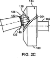
図2Cに示すように、凸状通路204および凹状ベース(図示せず)を有するスライド部材224を使用することによってこの状況を逆にすることができる。この状況では、ストロークの特定値における圧縮比は、直線路150を使用したストロークの同じ値における場合よりも大きい。
This situation can be reversed by using a
再び図1Aおよび図1Bを参照すると、ストロークが変わっても圧縮比が実質的に一定になるエンジンの例として、ジョイント110および伝達アーム106は、第一位置から第二位置まで1.4インチの距離だけ軸方向に移動するように構成される。通路150の角度αは約44.7°である。これは、約14.5°の最小スイング角度βと、約30°の最大スイング角度をもたらす。組立体軸線Aからピストン軸線Pまでの距離hは、約4.28インチである。これは、約2.3インチの最小ストロークと、4.6インチの最大ストロークをもたらす。最小ストロークでは、トップクリアランス距離dは、約0.l56インチであり、最大ストロークでは、トップクリアランス距離は、約0.413インチである。これにより、シリンダ118の端壁144が平坦でなく、0.1インチのストロークがでこぼこによって引き起こされる(完璧なシリンダと比較して)容積の変化を償うと仮定して、ストローク範囲の間約10:1の圧縮比になる。
Referring again to FIGS. 1A and 1B, as an example of an engine where the compression ratio remains substantially constant as the stroke changes, the joint 110 and
もしシリンダ118の端壁144が平坦であれば、圧縮比を提供するトップクリアランス距離は、最大ストロークで0.513インチであり、最小ストロークで0.256インチである。しかしながら、シリンダの端壁は通常平坦ではなく、容積を変更する。この変更された容積は、平坦な端壁144に必要なトップクリアランス距離から0.1インチを差し引くことによって考慮に入れられる。
If the
ストロークが増大するに従って圧縮比が線形的に減少する(またはその逆の)エンジンの例として、ジョイント110および伝達アーム106は、第一位置から第二位置まで約0.65インチの距離軸方向に移動するように構成される。通路150の角度αは約47.4°である。これにより、約14.5°の最小スイング角度βおよび、約32.1°の最大スイング角度になる。組立体軸線Aからピストン軸線Pまでの距離hは、約4.3インチである。これにより、約2.3インチの最小ストロークおよび、4.6インチの最大ストロークになる。最小ストロークでは、トップクリアランス距離dは、約0.065インチであり、最大ストロークでは、トップクリアランス距離は、約0.413インチである。
As an example of an engine in which the compression ratio decreases linearly as the stroke increases (or vice versa), the joint 110 and the
図3を参照すると、そのような寸法は、端壁144が平坦でなく、且つ0.1インチが平坦でないことによる変化した容積に原因があると仮定して、グラフ300に示すように、線形的に変化する圧縮比に備える。線302は、ストロークと圧縮比との線形関係を示す。示すように、圧縮比は、最小ストローク(約2.3インチ)における約15:1から最大ストローク(約4.6インチ)における約10:1まで線形的に変化する。
Referring to FIG. 3, such dimensions are linear, as shown in
図1A乃至図1Dに示す組立体100は、また、例えば冷凍圧縮機、空気ポンプまたはモータ、油圧ポンプまたはモータ等としての用途に適応させることができる。一般的に、これらの装置のために、ピストン端面138がシリンダ118の端壁144と接触することなく、できるだけ0に近いトップクリアランス距離dを有することが望ましい。かくして、組立体100が、これらの装置の一つとしての用途に適応されるとき、チャンネル134の通路は、所望のストロークの範囲の間、実質的に0のトップクリアランス距離dをもたらすように設計される。例えば、チャンネル134とジョイント110の位置決めとは、10/1000インチから20/1000インチの範囲のトップクリアランス距離dを提供する。
The
一般的に、ピストン組立体104の変位を変化させる製造公差および長期にわたるベアリングの摩耗を考慮に入れるある量のトップクリアランス距離dが存在する。したがって、与えられるトップクリアランス距離dの量は、製造公差と、ピストン組立体104の変位において期待される変化に依存する。加えて、製造公差によって、トップクリアランス距離のある変動が、最小ストローク位置と最大ストローク位置の間に存在し、変動の絶対量は、組立体寸法に依存する。しかしながら、トップ距離クリアランスdにおける変動は、最小ストローク位置と最大ストローク位置の間のストロークの変化量のパーセンテージとしては、2%以下に維持される。
In general, there is an amount of top clearance distance d that takes into account manufacturing tolerances that change the displacement of the
一定の圧縮比では、通路150は、実質的に0のトップクリアランス距離を提供するように、一般的に直線である。しかしながら、非直線通路を、例えば少なくとも一部がトップクリアランス距離dの変動を補償するために、またはストロークとトップクリアランス距離dの間に他の関係をもたらすために、使用してもよい。
At a constant compression ratio, the
図4を参照すると、組立体400は、モータ駆動のスクリューアクチュエータ148の代わりに、油圧シリンダ402、レバー404、およびスプリングリターン406が、ジョイント110および伝達アーム106を軸方向に移動させるのに使用されることをのぞいて、組立体100と同様である。
Referring to FIG. 4,
この実施では、ジョイント110は、サポート410の一端410aに取り付けられる。サポート410は、サポート410が組立体軸線Aに沿って直線的に移動することができるが、組立体軸線Aを中心に回転することができないように、キー止めされ、或いはスプラインである。サポート410の他端410bは、支点408に取り付けられたレバー404の端部404aに取り付けられている。レバー404の第二端部404bは、油圧シリンダ402のアーム402aに取り付けられている。オイルがシリンダ402に内に圧入されると、アーム402aはレバー404に向かって移動する。アーム402aがレバー404に向かって移動すると、アーム402aはレバー404の端部404bに力を及ぼし、レバー404を支点408を中心に回転させる。これにより、レバー404の端部404aを、伝達アーム106に向かって移動させ、それによってサポート410に力を及ぼし、それにより、サポート410および伝達アーム106をフライホイール130に向かって軸方向に移動させる。
In this implementation, the joint 110 is attached to one
伝達アーム106がフライホイール130に向かって移動すると、ストロークおよびクリアランスは、上述のように、スライド部材124がチャンネル134内でスライドし(それによりスイング角度βを変化させ)、ピストン組立体104が軸方向に移動する結果、同時に変えられる。
As the
オイルがシリンダ402から排出されると、アーム402aによってレバー404に及ぼされる力は、減少され、伝達アーム106がフライホイール130から遠ざかる方向に、それ故により短いストローク位置(つまりより小さいスイング角度β)に軸方向に移動する。一般的に、ピストンの力は、伝達アーム106に、伝達アーム106およびスライド部材124をチャンネル134内でより短いストローク位置に進める圧力を提供し、アーム402aによってレバー404に及ぼされる力は、スライド部材124がチャンネル134内でより長いストローク位置(より大きいスイング角度β)に移動するように、伝達アーム106を移動させるのに必要とされる。かくして、単純にアーム402aによって生じた力を減ずることにより、ピストンの力は、伝達アーム106およびスライド部材124をより短いストローク位置に移動させるように作用する。しかしながら、スプリングリターン406は、アーム402aによって及ぼされた力が減少するとき、スライド部材124がより短いストローク位置に確実に戻るようにするのに使用される。
As oil is drained from the
多数の実施が記載された。それにもかかわらず、様々な変更がなされてもよいことは理解されよう。例えば、五つのピストン組立体が記載されたが、より少ない、またより多いピストン組立体が使用されてもよい(例えば1,2,3,4,7,8等)。加えて、ピストン組立体104は、片端ピストン組立体として図示された。しかしながら、両端ピストン組立体もまた使用されてもよい。したがって、他の実施形態は、続く請求項の範囲内である。
A number of implementations have been described. Nevertheless, it will be understood that various changes may be made. For example, although five piston assemblies have been described, fewer and more piston assemblies may be used (eg, 1, 2, 3, 4, 7, 8, etc.). In addition, the
Claims (14)
シリンダに収容される少なくとも一つのピストンと、
ピストンに連結され、ノーズピンを含む伝達アームと、
チャンネルを画成する回転部材と、
回転部材によって画成されたチャンネル内に配置されたスライド部材と、
スライド部材内に収容され、回転部材が伝達アームに対して回転できるように伝達アームのノーズピンに連結されたノーズピンベアリングと、
ノーズピンベアリングと伝達アームの肩部の間で、ノーズピンに位置決めされているスラストベアリングとを備え、
伝達アームの移動は、ピストンの端面とシリンダの端壁との間のクリアランス距離を調整し、
伝達アームの移動により、ピストンのストロークが変えられるように、スライド部材をチャンネル内でスライドさせる、
ことを特徴とする組立体。A cylinder,
At least one piston housed in a cylinder;
A transmission arm coupled to the piston and including a nose pin ;
A rotating member defining a channel;
A slide member disposed in a channel defined by the rotating member;
A nose pin bearing housed in a slide member and coupled to the nose pin of the transmission arm so that the rotating member can rotate relative to the transmission arm;
A thrust bearing positioned on the nose pin between the nose pin bearing and the shoulder of the transmission arm;
The movement of the transmission arm adjusts the clearance distance between the end face of the piston and the end wall of the cylinder,
Slide the slide member in the channel so that the stroke of the piston can be changed by the movement of the transmission arm,
An assembly characterized by that.
請求項1に記載の組立体。The movement of the transmission arm adjusts the clearance distance between the end face of the piston and the end wall of the cylinder by changing the axial position of the piston in the cylinder.
The assembly according to claim 1.
請求項1に記載の組立体。The angle between the nose pin of the transmission arm, as is the angle between the center axis of the transmission arm and the assembly is connected to the nose pin bearing, the sliding of the sliding member within the channel, the transmission arm and the central axis Causing a change in piston stroke,
The assembly according to claim 1.
請求項1に記載の組立体。The movement of the transmission arm simultaneously adjusts the clearance distance between the end face of the piston and the end wall of the cylinder, and slides the member in the channel so that the stroke of the piston can be changed.
The assembly according to claim 1.
請求項1に記載の組立体。The channel follows a straight path,
The assembly according to claim 1.
請求項1に記載の組立体。The channel follows a curved path,
The assembly according to claim 1.
請求項1に記載の組立体。A spring return that biases the member toward a shorter stroke position within the channel;
The assembly according to claim 1.
請求項1に記載の組立体。The assembly is a refrigeration compressor,
The assembly according to claim 1.
請求項8に記載の組立体。The movement of the transmission arm adjusts the clearance distance between the end face of the piston and the end wall of the cylinder such that a substantially zero top clearance distance is maintained for different strokes.
The assembly according to claim 8 .
請求項1に記載の組立体。The assembly is a combustion engine;
The assembly according to claim 1.
請求項16に記載の組立体。The movement of the transmission arm adjusts the clearance distance between the end face of the piston and the end wall of the cylinder so that a substantially constant compression ratio is maintained for different strokes.
The assembly according to claim 16.
請求項16に記載の組立体。The slide member and channel define a stroke-clearance relationship that provides a compression ratio defined for the corresponding stroke value.
The assembly according to claim 16.
請求項1に記載の組立体。The movement of the transmission arm adjusts the clearance distance between the end face of the piston and the end wall of the cylinder so that a constant clearance distance is maintained for different strokes,
The assembly according to claim 1.
シリンダ内に収容される少なくとも一つのピストンと、 At least one piston housed in the cylinder;
ピストンに連結され、ノーズピンを含む伝達アームと、 A transmission arm coupled to the piston and including a nose pin;
チャンネルを画成する回転部材と、 A rotating member defining a channel;
回転部材によって画成されたチャンネル内に配置されたスライド部材と、 A slide member disposed in a channel defined by the rotating member;
スライド部材内に収容され、回転部材が伝達アームに対して回転できるように伝達アームのノーズピンに連結されたノーズピンベアリングと、 A nose pin bearing housed in a slide member and coupled to the nose pin of the transmission arm so that the rotating member can rotate relative to the transmission arm;
ノーズピンベアリングと伝達アームの肩部の間で、ノーズピンに位置決めされているスラストベアリングとを備える組立体を準備する工程と、 Providing an assembly comprising a thrust bearing positioned on the nose pin between the nose pin bearing and the shoulder of the transmission arm;
伝達アームを軸方向に移動させて、ピストンの端面との間のクリアランスを調整し、それと同時に、ピストンのストロークが変えられるようにスライド部材をチャンネル内でスライドさせる工程と、を備えることを特徴とする方法。 Moving the transmission arm in the axial direction to adjust the clearance with the end face of the piston, and simultaneously sliding the slide member in the channel so that the stroke of the piston can be changed. how to.
Applications Claiming Priority (3)
| Application Number | Priority Date | Filing Date | Title |
|---|---|---|---|
| US57421904P | 2004-05-26 | 2004-05-26 | |
| US60/574,219 | 2004-05-26 | ||
| PCT/US2005/018425 WO2005119010A1 (en) | 2004-05-26 | 2005-05-26 | Variable stroke and clearance mechanism |
Publications (2)
| Publication Number | Publication Date |
|---|---|
| JP2008500493A JP2008500493A (en) | 2008-01-10 |
| JP4808708B2 true JP4808708B2 (en) | 2011-11-02 |
Family
ID=34971370
Family Applications (1)
| Application Number | Title | Priority Date | Filing Date |
|---|---|---|---|
| JP2007515313A Expired - Fee Related JP4808708B2 (en) | 2004-05-26 | 2005-05-26 | Variable stroke and clearance mechanism |
Country Status (5)
| Country | Link |
|---|---|
| US (1) | US7325476B2 (en) |
| EP (1) | EP1766187A1 (en) |
| JP (1) | JP4808708B2 (en) |
| BR (1) | BRPI0511592A (en) |
| WO (1) | WO2005119010A1 (en) |
Families Citing this family (10)
| Publication number | Priority date | Publication date | Assignee | Title |
|---|---|---|---|---|
| US7331271B2 (en) * | 2001-02-08 | 2008-02-19 | R. Sanderson Management, Inc. | Variable stroke/clearance mechanism |
| US7451687B2 (en) * | 2005-12-07 | 2008-11-18 | Thomas Industries, Inc. | Hybrid nutating pump |
| US20110085920A1 (en) * | 2009-10-14 | 2011-04-14 | Sean Kelly Summers | Method and apparatus for dynamic impulse signal attenuation simulation |
| US9109446B1 (en) * | 2011-02-07 | 2015-08-18 | Ameriband, Llc | Continuously variable displacement engine |
| US9896933B1 (en) * | 2011-02-07 | 2018-02-20 | Ameriband, Llc | Continuously variable displacement engine |
| US10041405B1 (en) * | 2011-02-07 | 2018-08-07 | Ameriband, Llc | Continuously variable displacement engine |
| US9540932B1 (en) * | 2011-02-07 | 2017-01-10 | Ameriband, Llc | Continuously variable displacement engine |
| CN105229289A (en) * | 2013-03-12 | 2016-01-06 | 德纳有限公司 | The Waste Heat Recovery System (WHRS) strengthened |
| US9581057B1 (en) | 2014-08-20 | 2017-02-28 | Ameriband, Llc | Valve actuator system capable of operating multiple valves with a single cam |
| US11204022B2 (en) | 2018-08-14 | 2021-12-21 | Milwaukee Electric Tool Corporation | Air compressor |
Citations (10)
| Publication number | Priority date | Publication date | Assignee | Title |
|---|---|---|---|---|
| US1392389A (en) * | 1920-09-01 | 1921-10-04 | Anderson Lars | Mechanical movement |
| US1977424A (en) * | 1927-09-21 | 1934-10-16 | Hosmer L Blum | Fluid meter |
| US2539880A (en) * | 1946-06-26 | 1951-01-30 | Wildhaber Ernest | Variable stroke engine |
| US2940325A (en) * | 1957-02-15 | 1960-06-14 | Nakesch Michael | Internal combustion engine with swash plate drive |
| JPS5078728A (en) * | 1973-11-09 | 1975-06-26 | ||
| DE2633618A1 (en) * | 1976-07-27 | 1978-02-02 | Josef Jobelius | Piston engine designed for internal stepless torque variation - using axially movable motion conversion element to vary stroke |
| JPH03149319A (en) * | 1989-07-15 | 1991-06-25 | Kitaguchi Masahiro | Crankless engine |
| JPH04255501A (en) * | 1990-08-11 | 1992-09-10 | Jaguar Cars Ltd | Reciprocating piston device |
| JP2001516837A (en) * | 1997-09-15 | 2001-10-02 | アール サンダーソン マネージメント インコーポレイテッド | Variable compression piston assembly |
| WO2009102889A1 (en) * | 2008-02-15 | 2009-08-20 | Sonitus Medical, Inc. | Headset systems and methods |
Family Cites Families (145)
| Publication number | Priority date | Publication date | Assignee | Title |
|---|---|---|---|---|
| US1194258A (en) | 1916-08-08 | walker | ||
| US748559A (en) | 1901-04-13 | 1903-12-29 | Alexander J Peet | Compound engine. |
| US812636A (en) | 1904-07-11 | 1906-02-13 | Gen Electric | Variable-stroke crank. |
| US821546A (en) | 1905-04-10 | 1906-05-22 | Harry E Smallbone | Multiple-cylinder engine. |
| US1019521A (en) | 1910-04-18 | 1912-03-05 | Universal Speed Control Company | Pump. |
| US1131614A (en) | 1910-12-12 | 1915-03-09 | Electric Time Recorder Company | Electric motor. |
| US1210649A (en) | 1913-01-22 | 1917-01-02 | Utility Compressor Company | Mechanical movement. |
| US1161152A (en) | 1914-02-25 | 1915-11-23 | Tage Georg Nyborg | Multicylinder internal-combustion engine of the horizontal type. |
| US1161258A (en) | 1915-04-24 | 1915-11-23 | Thomas W Shelton | Portable crane. |
| US1255973A (en) | 1916-02-23 | 1918-02-12 | Almen Crosby Motors Co Inc | Engine. |
| USRE15442E (en) | 1917-04-21 | 1922-09-05 | almen | |
| US1659374A (en) | 1923-05-05 | 1928-02-14 | Waterbury Tool Co | Fluid-pressure device |
| US1648000A (en) | 1924-05-28 | 1927-11-08 | Lee Engineering Res Corp | Variable-speed transmission |
| US1577010A (en) | 1925-10-26 | 1926-03-16 | New England Motor Company Inc | Engine |
| US1673280A (en) | 1926-03-03 | 1928-06-12 | Evans Arthur Frederick | Internal-combustion engine |
| US1857656A (en) | 1928-09-26 | 1932-05-10 | Oldfield Lee | Two stroke cycle internal combustion engine |
| US1817063A (en) | 1928-11-03 | 1931-08-04 | Carrie James | Transmission mechanism |
| US1772977A (en) | 1929-02-25 | 1930-08-12 | Italien American Motors Inc | Internal-combustion engine |
| DE531753C (en) | 1929-08-27 | 1931-08-22 | Wichert Hulsebos | Device for transmitting the piston movement to a wobble element |
| US1968470A (en) | 1930-01-31 | 1934-07-31 | Szombathy Max | Power transmission for internal combustion engines |
| US1894033A (en) | 1930-07-31 | 1933-01-10 | Michellcrankless Engines Corp | Engine |
| US1886770A (en) | 1930-08-12 | 1932-11-08 | Robert D Wehr | Internal combustion engine |
| US2042730A (en) | 1932-03-17 | 1936-06-02 | Bristol Tramways & Carriage Co | Valve mechanism of internal combustion engines |
| US2112934A (en) | 1932-05-11 | 1938-04-05 | Stinnes Hanns Heinz | Swash plate drive system and the like |
| US2048272A (en) | 1932-11-22 | 1936-07-21 | Lewis S Murray | Variable capacity pump |
| US2104391A (en) | 1935-12-21 | 1938-01-04 | Bristol Tramways & Carriage Co | Swash mechanism |
| US2151614A (en) | 1936-09-24 | 1939-03-21 | Nevatt Axial Engines Ltd | Swash plate type engine |
| US2247527A (en) | 1938-11-21 | 1941-07-01 | Stinnes Hanns Heinz | Swash-ring driving mechanism |
| US2302995A (en) | 1939-02-15 | 1942-11-24 | Frederick J Holmes | Wobble plate structure |
| US2282722A (en) | 1940-01-30 | 1942-05-12 | Edwin S Hall | Crosshead mechanism |
| US2263561A (en) | 1940-08-07 | 1941-11-25 | Arnold E Biermann | Variable compression ratio barreltype engine |
| US2256079A (en) | 1940-12-03 | 1941-09-16 | Watson Stillman Co | Swash plate mechanism |
| US2335048A (en) | 1942-04-01 | 1943-11-23 | Gen Machinery Corp | Mechanism for the interconversion of reciprocation and rotation |
| US2303838A (en) | 1942-04-01 | 1942-12-01 | Edwin S Hall | Mechanism for the interconversion of reciprocation and rotation |
| US2532254A (en) | 1942-07-04 | 1950-11-28 | Bouchard Gaston Robert | Device for converting motion |
| US2341203A (en) | 1942-08-31 | 1944-02-08 | William J Borer | Rotary engine |
| US2357735A (en) | 1943-07-03 | 1944-09-05 | Rogers Diesel And Aircraft Cor | Mechanism for the interconversion of reciprocation and rotation |
| US2465510A (en) | 1944-10-23 | 1949-03-29 | Lapointe Machine Tool Co | Hydraulic pump |
| US2513083A (en) | 1945-05-24 | 1950-06-27 | Samuel B Eckert | Wobbler drive mechanism |
| US2653484A (en) | 1950-09-05 | 1953-09-29 | Zecher Ernest | Compensating mechanism connecting reciprocating member to a rotating member |
| US2737895A (en) | 1952-11-19 | 1956-03-13 | Oilgear Co | Axial type pump |
| US2827792A (en) | 1953-01-22 | 1958-03-25 | Samuel B Eckert | Damping device for wabbler type engines |
| US2957421A (en) | 1954-03-17 | 1960-10-25 | Bendix Corp | Fuel supply pump for prime movers |
| US2910973A (en) | 1955-09-15 | 1959-11-03 | Julius E Witzky | Variable compression ratio type engine |
| US3077118A (en) | 1958-04-30 | 1963-02-12 | Gen Motors Corp | Variable displacement pump mechanism |
| US3076345A (en) | 1959-10-20 | 1963-02-05 | Hispano Suiza Sa | Piston machines of the barrel type |
| US3000367A (en) | 1960-08-17 | 1961-09-19 | Hodge M Eagleson | Double acting two-stroke cycle engine |
| US3182644A (en) | 1961-07-24 | 1965-05-11 | Otto V Dritina | Internal combustion engine |
| US3198022A (en) | 1962-01-23 | 1965-08-03 | Waern Bror Algor De | Wobble plate anchor control mechanism |
| US3176667A (en) | 1962-10-22 | 1965-04-06 | Hammer Wilhelm | Piston engine |
| US3273344A (en) | 1963-05-10 | 1966-09-20 | Gen Motors Corp | Transmission |
| GB1067962A (en) | 1964-02-15 | 1967-05-10 | Hydraulik Gmbh | Improvements in/or relating to swash plate pumps |
| US3386425A (en) | 1966-07-11 | 1968-06-04 | Arthur L. Morsell | Internal combustion engines |
| US3590188A (en) | 1966-09-01 | 1971-06-29 | Westinghouse Electric Corp | Fluid-blast circuit interrupter with piston assembly and electromagnetic driving means |
| US3528317A (en) | 1969-04-14 | 1970-09-15 | Clessie L Cummins | Internal combustion engine |
| US3654906A (en) | 1969-05-09 | 1972-04-11 | Airas T | Axial cylinder rotary engine |
| DE2238582A1 (en) | 1972-08-04 | 1974-02-21 | Linde Ag | AXIAL PISTON MACHINE |
| US3842440A (en) | 1972-09-01 | 1974-10-22 | E Karlson | Implantable linear motor prosthetic heart and control system therefor |
| SE406001B (en) | 1972-10-23 | 1979-01-15 | Ifield Richard J | PISTON PUMP WITH VARIABLE IMPACT VOLUME |
| JPS533471B2 (en) | 1973-03-22 | 1978-02-07 | ||
| US3847124A (en) | 1973-03-30 | 1974-11-12 | L Kramer | Internal combustion engine |
| US3959983A (en) | 1973-04-04 | 1976-06-01 | Borg-Warner Corporation | Variable capacity wobble plate compressor |
| US3861829A (en) | 1973-04-04 | 1975-01-21 | Borg Warner | Variable capacity wobble plate compressor |
| NL7308702A (en) | 1973-06-22 | 1974-12-24 | ||
| GB1481456A (en) | 1973-10-12 | 1977-07-27 | Rohs U | Axial piston internal combustion engine |
| US3945359A (en) | 1973-11-27 | 1976-03-23 | Ryuzi Asaga | Rotor engine |
| US4060178A (en) | 1974-05-10 | 1977-11-29 | Miller Mfg. Co. Of Schiller Park, Inc. | Metering pump |
| US3969046A (en) | 1974-07-12 | 1976-07-13 | Wynn James M | Metering pump system |
| RO64732A2 (en) | 1974-09-02 | 1978-04-15 | Inst Pentru Creatie Stintific | INTERNAL COMBUSTION ENGINE HAVING VARIABLE CYLINDRICAL CAPABILITY |
| DE2446806C3 (en) | 1974-10-01 | 1982-12-23 | Lewa Herbert Ott Gmbh + Co, 7250 Leonberg | Stroke adjustment device on pumps |
| US4011842A (en) | 1975-09-08 | 1977-03-15 | Francis William Davies | Piston machine |
| US4077269A (en) | 1976-02-26 | 1978-03-07 | Lang Research Corporation | Variable displacement and/or variable compression ratio piston engine |
| US4075933A (en) | 1976-06-04 | 1978-02-28 | Gresen Manufacturing Company | Hydraulic pump or motor |
| SE7706905L (en) | 1976-07-12 | 1978-01-13 | Vadetec Sa | ENERGY CONVERSION MACHINE |
| NL7608350A (en) | 1976-07-28 | 1978-01-31 | Philips Nv | DRIVEWORK. |
| US4094202A (en) | 1976-11-03 | 1978-06-13 | Vadetec Corporation | Piston stroke varying mechanism for expansible chamber energy conversion machines |
| US4100815A (en) | 1976-11-22 | 1978-07-18 | Vadetec Corporation | Variable displacement piston engine |
| US4144771A (en) | 1977-04-07 | 1979-03-20 | Vadetec Corporation | Variable stroke piston type engine |
| US4112826A (en) | 1977-05-02 | 1978-09-12 | General Motors Corporation | Variable displacement reciprocating piston machine |
| US4174684A (en) | 1977-05-23 | 1979-11-20 | Hallmann Eckhard P | Variable stroke internal combustion engine |
| US4178135A (en) | 1977-12-16 | 1979-12-11 | Borg-Warner Corporation | Variable capacity compressor |
| US4171072A (en) | 1978-02-08 | 1979-10-16 | Geo B. Davis, Jr. | Hand held electric caulking gun |
| US4231724A (en) | 1978-03-09 | 1980-11-04 | Hope Henry F | Adjustable metering pump |
| US4236881A (en) | 1978-05-03 | 1980-12-02 | Ecodyne Corporation | Liquid metering pump |
| US4235116A (en) | 1978-05-10 | 1980-11-25 | U.S. Philips Corporation | Balanced variable wobble plate drive |
| US4178136A (en) | 1978-06-02 | 1979-12-11 | General Motors Corporation | Guide shoe members for wobble plate compressor |
| US4285640A (en) | 1978-08-03 | 1981-08-25 | Kabushiki Kaisha Toyoda Jidoshokki Seisakusho | Swash plate type compressor |
| US4203396A (en) | 1978-10-19 | 1980-05-20 | Berger Alfred H | Barrel engine with rocking ball drive |
| US4208926A (en) | 1978-11-08 | 1980-06-24 | Caterpillar Tractor Co. | Nutating drive |
| NL7900076A (en) | 1979-01-05 | 1980-07-08 | Philips Nv | DRIVING FOR A MACHINE WITH PISTON AND REVERSE PISTONS WITH VARIABLE STROKE. |
| FR2461127A1 (en) | 1979-03-30 | 1981-01-30 | Creusot Loire | ALTERNATIVE PUMP |
| US4285303A (en) | 1979-04-19 | 1981-08-25 | Charles Leach | Swash plate internal combustion engine |
| US4270495A (en) | 1979-05-31 | 1981-06-02 | General Motors Corporation | Variable displacement piston engine |
| US4297085A (en) | 1979-10-31 | 1981-10-27 | General Motors Corporation | Guide mechanism for compressor socket plate |
| US4323333A (en) | 1979-11-23 | 1982-04-06 | R. A. Industries | Piston metering pump |
| US4349130A (en) | 1980-03-03 | 1982-09-14 | Woolfolk Chemical Works, Inc. | Liquid metering pump |
| US4433596A (en) * | 1980-03-11 | 1984-02-28 | Joseph Scalzo | Wabbler plate engine mechanisms |
| DE3026765A1 (en) * | 1980-07-15 | 1982-02-11 | Linde Ag, 6200 Wiesbaden | AXIAL PISTON PUMP FOR TWO FLOWERS |
| WO1982001570A1 (en) * | 1980-11-01 | 1982-05-13 | Milu Petre | Two-strokes axial pistons engine |
| US4418586A (en) * | 1981-05-20 | 1983-12-06 | General Motors Corporation | Swash plate drive mechanism |
| US4345174A (en) | 1981-06-01 | 1982-08-17 | Angus Motor Corporation | Electromagnetic engine |
| FR2510698A1 (en) * | 1981-07-30 | 1983-02-04 | Creusot Loire | MOVEMENT TRANSFORMATION MECHANISM |
| US4454426A (en) * | 1981-08-17 | 1984-06-12 | New Process Industries, Inc. | Linear electromagnetic machine |
| DE3135605A1 (en) * | 1981-09-09 | 1983-03-17 | Linde Ag, 6200 Wiesbaden | ADJUSTABLE WASHING DISC AXIAL PISTON MACHINE WITH SLIDING BEARING WEIGHING BODY |
| IT1154423B (en) * | 1982-01-13 | 1987-01-21 | Fiat Auto Spa | ALTERNATIVE PISTON MOTOR WITH INCLINED DISC MECHANISM FOR THE TRANSFORMATION OF THE ALTERNATIVE MOTOR INTO A ROTARY MOTOR PARTICULARLY FOR MOTOR VEHICLES |
| US4491057A (en) * | 1982-08-03 | 1985-01-01 | Anthony D. Morris | Axial piston machine having double acting pistons and a rotary control valve |
| DE3505133A1 (en) * | 1985-02-14 | 1986-08-14 | Lewa Herbert Ott Gmbh + Co, 7250 Leonberg | HYDRAULICALLY ACTUATED LIFT ADJUSTMENT |
| US4920859A (en) * | 1986-08-01 | 1990-05-01 | Eaton Corporaton | Radial piston pump and motor |
| US4729717A (en) * | 1986-12-24 | 1988-03-08 | Vickers, Incorporated | Power transmission |
| JP2701919B2 (en) * | 1988-03-02 | 1998-01-21 | 株式会社デンソー | Variable displacement swash plate type compressor |
| US5007385A (en) * | 1989-07-15 | 1991-04-16 | Hiromasa Kitaguchi | Crankless engine |
| EP0433649A1 (en) * | 1989-11-17 | 1991-06-26 | ASKOLL S.p.A. | Fluid metering pump |
| US5094195A (en) * | 1990-04-20 | 1992-03-10 | The Cessna Aircraft Company | Axial cylinder internal combustion engine |
| US5102306A (en) * | 1990-05-08 | 1992-04-07 | Liu Kuo Sheng | AC/DC air pump |
| US5025757A (en) * | 1990-09-13 | 1991-06-25 | Larsen Gregory J | Reciprocating piston engine with a varying compression ratio |
| KR950003458Y1 (en) * | 1990-11-29 | 1995-05-02 | 가부시끼가이샤 도요다지도쇽끼 세이사꾸쇼 | Swash plate compressor |
| US5113809A (en) * | 1991-04-26 | 1992-05-19 | Ellenburg George W | Axial cylinder internal combustion engine having variable displacement |
| JPH04347380A (en) * | 1991-05-22 | 1992-12-02 | Honda Motor Co Ltd | Radial plunger unit with compression ratio adjusting mechanism |
| SE513061C2 (en) * | 1992-06-30 | 2000-06-26 | Fanja Ltd | Method and apparatus for changing the compression ratio in an internal combustion engine |
| US5405252A (en) * | 1993-01-06 | 1995-04-11 | Nikkanen; Erik | Metering pump |
| BR9406392A (en) * | 1993-05-07 | 1996-01-16 | Whisper Tech Ltd | Oscillating fork assembly |
| US5397922A (en) * | 1993-07-02 | 1995-03-14 | Paul; Marius A. | Integrated thermo-electro engine |
| JP3031154B2 (en) * | 1994-02-28 | 2000-04-10 | 株式会社日立製作所 | Constant velocity joint |
| US5596920A (en) * | 1994-04-06 | 1997-01-28 | Kabushiki Kaisha Toyoda Jidoshokki Seisakusho | Swash plate type compressor |
| JP3429100B2 (en) * | 1995-03-22 | 2003-07-22 | 株式会社豊田自動織機 | Double head swash plate type compressor |
| JPH08326655A (en) * | 1995-06-05 | 1996-12-10 | Calsonic Corp | Swash plate compressor |
| AUPN391595A0 (en) * | 1995-06-30 | 1995-07-27 | Orbital Engine Company (Australia) Proprietary Limited | Improvements to fuel pumps |
| US6074174A (en) * | 1998-01-15 | 2000-06-13 | Thomas Industries Inc. | Fluid pumping apparatus |
| DE19527645B4 (en) * | 1995-07-28 | 2004-09-09 | Linde Ag | Swashplate type axial piston machine |
| US5894782A (en) * | 1996-05-24 | 1999-04-20 | Danfoss A/S | Compressor |
| US6012903A (en) * | 1996-07-22 | 2000-01-11 | Uni-Mist, Inc. | Positive-displacement liquid-metering pump with continuously variable output |
| US5762039A (en) * | 1997-01-20 | 1998-06-09 | The Cessna Aircraft Company | Barrel engine connecting rod |
| JPH10213064A (en) * | 1997-01-31 | 1998-08-11 | Zexel Corp | Variable capacity swash plate type compressor |
| US5890462A (en) * | 1997-06-02 | 1999-04-06 | Bassett; Wladimir A | Tangential driven rotary engine |
| JP3476657B2 (en) * | 1997-06-05 | 2003-12-10 | 株式会社丸山製作所 | Plunger pump and multiple plunger pump device |
| US6446587B1 (en) * | 1997-09-15 | 2002-09-10 | R. Sanderson Management, Inc. | Piston engine assembly |
| US7007589B1 (en) * | 1997-09-15 | 2006-03-07 | R. Sanderson Management, Inc. | Piston assembly |
| US6698394B2 (en) * | 1999-03-23 | 2004-03-02 | Thomas Engine Company | Homogenous charge compression ignition and barrel engines |
| DE19939131A1 (en) * | 1999-08-18 | 2001-03-08 | Zexel Gmbh | Axial piston engine with an infinitely adjustable piston stroke |
| US7011469B2 (en) * | 2001-02-07 | 2006-03-14 | R. Sanderson Management, Inc. | Piston joint |
| US7331271B2 (en) * | 2001-02-08 | 2008-02-19 | R. Sanderson Management, Inc. | Variable stroke/clearance mechanism |
| WO2002063139A1 (en) * | 2001-02-08 | 2002-08-15 | R. Sanderson Management, Inc. | Variable stroke/clearance mechanism |
| JP4496662B2 (en) * | 2001-04-20 | 2010-07-07 | 株式会社豊田自動織機 | Swash plate in swash plate compressor |
| US6854377B2 (en) * | 2001-11-02 | 2005-02-15 | R. Sanderson Management, Inc. | Variable stroke balancing |
| US6913447B2 (en) * | 2002-01-22 | 2005-07-05 | R. Sanderson Management, Inc. | Metering pump with varying piston cylinders, and with independently adjustable piston strokes |
-
2005
- 2005-05-26 BR BRPI0511592-2A patent/BRPI0511592A/en not_active Application Discontinuation
- 2005-05-26 EP EP05755428A patent/EP1766187A1/en not_active Withdrawn
- 2005-05-26 WO PCT/US2005/018425 patent/WO2005119010A1/en active Application Filing
- 2005-05-26 US US11/137,706 patent/US7325476B2/en not_active Expired - Fee Related
- 2005-05-26 JP JP2007515313A patent/JP4808708B2/en not_active Expired - Fee Related
Patent Citations (10)
| Publication number | Priority date | Publication date | Assignee | Title |
|---|---|---|---|---|
| US1392389A (en) * | 1920-09-01 | 1921-10-04 | Anderson Lars | Mechanical movement |
| US1977424A (en) * | 1927-09-21 | 1934-10-16 | Hosmer L Blum | Fluid meter |
| US2539880A (en) * | 1946-06-26 | 1951-01-30 | Wildhaber Ernest | Variable stroke engine |
| US2940325A (en) * | 1957-02-15 | 1960-06-14 | Nakesch Michael | Internal combustion engine with swash plate drive |
| JPS5078728A (en) * | 1973-11-09 | 1975-06-26 | ||
| DE2633618A1 (en) * | 1976-07-27 | 1978-02-02 | Josef Jobelius | Piston engine designed for internal stepless torque variation - using axially movable motion conversion element to vary stroke |
| JPH03149319A (en) * | 1989-07-15 | 1991-06-25 | Kitaguchi Masahiro | Crankless engine |
| JPH04255501A (en) * | 1990-08-11 | 1992-09-10 | Jaguar Cars Ltd | Reciprocating piston device |
| JP2001516837A (en) * | 1997-09-15 | 2001-10-02 | アール サンダーソン マネージメント インコーポレイテッド | Variable compression piston assembly |
| WO2009102889A1 (en) * | 2008-02-15 | 2009-08-20 | Sonitus Medical, Inc. | Headset systems and methods |
Also Published As
| Publication number | Publication date |
|---|---|
| BRPI0511592A (en) | 2008-01-02 |
| JP2008500493A (en) | 2008-01-10 |
| US7325476B2 (en) | 2008-02-05 |
| WO2005119010A1 (en) | 2005-12-15 |
| EP1766187A1 (en) | 2007-03-28 |
| US20050268869A1 (en) | 2005-12-08 |
Similar Documents
| Publication | Publication Date | Title |
|---|---|---|
| JP4808708B2 (en) | Variable stroke and clearance mechanism | |
| US7677871B2 (en) | High-efficiency, large angle, variable displacement hydraulic pump/motor | |
| JPH1037850A (en) | Reciprocating engine equipped with wobble plate transmission | |
| JP2003074439A5 (en) | ||
| US6752120B2 (en) | Crankshaft and engine | |
| US4301695A (en) | Reciprocating piston machine | |
| US6591797B2 (en) | Variable fulcrum rocker arm | |
| JP4656666B2 (en) | Swash ring compressor | |
| JP3373733B2 (en) | Reciprocating piston type machine with wobble plate device | |
| US7213545B2 (en) | Reciprocating engine | |
| JP4207974B2 (en) | Variable compression ratio internal combustion engine | |
| JP2006063995A (en) | Link member for internal combustion engine | |
| EP0471451A1 (en) | Reciprocating piston device | |
| US9752570B2 (en) | Variable displacement compressor and expander | |
| US6210124B1 (en) | Variable swash plate compressor | |
| JPS5840666B2 (en) | Reciprocating pump drive device | |
| US6354809B1 (en) | Variable swash plate compressor | |
| WO2021065038A1 (en) | Compressor | |
| EP1813791A1 (en) | Internal combustion engine | |
| JPS63309785A (en) | Compressor | |
| JP2017141718A (en) | Plunger pump | |
| JPH0526052A (en) | Structure of straight engine | |
| JPH01267374A (en) | Swash type variable volume type compressor | |
| JP2018112117A (en) | Variable compression ratio internal combustion engine | |
| JPS62162777A (en) | Variable delivery control type compressor |
Legal Events
| Date | Code | Title | Description |
|---|---|---|---|
| A621 | Written request for application examination |
Free format text: JAPANESE INTERMEDIATE CODE: A621 Effective date: 20080526 |
|
| A131 | Notification of reasons for refusal |
Free format text: JAPANESE INTERMEDIATE CODE: A131 Effective date: 20100927 |
|
| A601 | Written request for extension of time |
Free format text: JAPANESE INTERMEDIATE CODE: A601 Effective date: 20101224 |
|
| A602 | Written permission of extension of time |
Free format text: JAPANESE INTERMEDIATE CODE: A602 Effective date: 20110106 |
|
| A521 | Written amendment |
Free format text: JAPANESE INTERMEDIATE CODE: A523 Effective date: 20110328 |
|
| TRDD | Decision of grant or rejection written | ||
| A01 | Written decision to grant a patent or to grant a registration (utility model) |
Free format text: JAPANESE INTERMEDIATE CODE: A01 Effective date: 20110719 |
|
| A01 | Written decision to grant a patent or to grant a registration (utility model) |
Free format text: JAPANESE INTERMEDIATE CODE: A01 |
|
| A61 | First payment of annual fees (during grant procedure) |
Free format text: JAPANESE INTERMEDIATE CODE: A61 Effective date: 20110817 |
|
| FPAY | Renewal fee payment (event date is renewal date of database) |
Free format text: PAYMENT UNTIL: 20140826 Year of fee payment: 3 |
|
| R150 | Certificate of patent or registration of utility model |
Free format text: JAPANESE INTERMEDIATE CODE: R150 |
|
| R250 | Receipt of annual fees |
Free format text: JAPANESE INTERMEDIATE CODE: R250 |
|
| R250 | Receipt of annual fees |
Free format text: JAPANESE INTERMEDIATE CODE: R250 |
|
| R250 | Receipt of annual fees |
Free format text: JAPANESE INTERMEDIATE CODE: R250 |
|
| R250 | Receipt of annual fees |
Free format text: JAPANESE INTERMEDIATE CODE: R250 |
|
| LAPS | Cancellation because of no payment of annual fees |