JP4801369B2 - Planting equipment and water supply / drainage base. - Google Patents
Planting equipment and water supply / drainage base. Download PDFInfo
- Publication number
- JP4801369B2 JP4801369B2 JP2005118104A JP2005118104A JP4801369B2 JP 4801369 B2 JP4801369 B2 JP 4801369B2 JP 2005118104 A JP2005118104 A JP 2005118104A JP 2005118104 A JP2005118104 A JP 2005118104A JP 4801369 B2 JP4801369 B2 JP 4801369B2
- Authority
- JP
- Japan
- Prior art keywords
- base
- locking means
- hollow body
- soil layer
- drainage
- Prior art date
- Legal status (The legal status is an assumption and is not a legal conclusion. Google has not performed a legal analysis and makes no representation as to the accuracy of the status listed.)
- Expired - Fee Related
Links
Images


Classifications
-
- Y—GENERAL TAGGING OF NEW TECHNOLOGICAL DEVELOPMENTS; GENERAL TAGGING OF CROSS-SECTIONAL TECHNOLOGIES SPANNING OVER SEVERAL SECTIONS OF THE IPC; TECHNICAL SUBJECTS COVERED BY FORMER USPC CROSS-REFERENCE ART COLLECTIONS [XRACs] AND DIGESTS
- Y02—TECHNOLOGIES OR APPLICATIONS FOR MITIGATION OR ADAPTATION AGAINST CLIMATE CHANGE
- Y02A—TECHNOLOGIES FOR ADAPTATION TO CLIMATE CHANGE
- Y02A30/00—Adapting or protecting infrastructure or their operation
- Y02A30/24—Structural elements or technologies for improving thermal insulation
- Y02A30/254—Roof garden systems; Roof coverings with high solar reflectance
-
- Y—GENERAL TAGGING OF NEW TECHNOLOGICAL DEVELOPMENTS; GENERAL TAGGING OF CROSS-SECTIONAL TECHNOLOGIES SPANNING OVER SEVERAL SECTIONS OF THE IPC; TECHNICAL SUBJECTS COVERED BY FORMER USPC CROSS-REFERENCE ART COLLECTIONS [XRACs] AND DIGESTS
- Y02—TECHNOLOGIES OR APPLICATIONS FOR MITIGATION OR ADAPTATION AGAINST CLIMATE CHANGE
- Y02B—CLIMATE CHANGE MITIGATION TECHNOLOGIES RELATED TO BUILDINGS, e.g. HOUSING, HOUSE APPLIANCES OR RELATED END-USER APPLICATIONS
- Y02B80/00—Architectural or constructional elements improving the thermal performance of buildings
- Y02B80/32—Roof garden systems
Description
この発明は、植木、草花その他の植物を簡便に植栽することのできる装置、特に建造物の屋上や屋根等で植物を栽培するために設けられる植栽装置における係止手段に関し、詳しくは客土層の盛り込み時の高さ基準となりかつ前記防風ネットを係止するとともに構築する客土層の厚さに対応して高さを変更できる係止手段に関するものである。 The present invention relates to a device for easily planting plants, flowers and other plants , and more particularly to a locking means in a planting device provided for cultivating plants on the rooftop or roof of a building. The present invention relates to a locking means that serves as a height reference when the soil layer is incorporated and that can lock the windproof net and can change the height in accordance with the thickness of the customer soil layer to be constructed.
近年、建造物の屋上やその他の空間に大規模に植物を植栽し、都市部における無機的な空間の緑化を図る試みが盛んになされるようになっている。
このような時、多くの場合は、建造物等のスラブ面の防水層上に押えのコンクリート層を形成し、この上に、植栽層として、砂、砂利等からなる砂利層と、客土層を順次積層して植物を植栽するようにしている。
In recent years, attempts have been actively made to plant plants on a large scale on the rooftops of buildings and other spaces, and to plant green spaces in urban areas.
In such a case, in many cases, a concrete layer of a presser foot is formed on a waterproof layer of a slab surface of a building or the like, and a gravel layer made of sand, gravel, etc. is used as a planting layer, Plants are planted by laminating layers one after another.
しかしながら、植物にとって十分な保水性、排水性を得るためには、防水層にかなりの土砂を導入する必要があり、しかもコンクリート層はかなりの重量を有するため、これらの重量が建造物に悪影響を及ぼすという問題がある。
そこで、本出願人は、先に保水性、排水性に優れた軽量の植栽装置を開示している(例えば特許2531542号公報参照)。
However, in order to obtain sufficient water retention and drainage for plants, it is necessary to introduce a considerable amount of earth and sand into the waterproof layer, and the concrete layer has a considerable weight, so these weights have an adverse effect on the building. There is a problem of affecting.
Therefore, the present applicant has previously disclosed a lightweight planting device excellent in water retention and drainage (see, for example, Japanese Patent No. 2531542).
この植栽装置は、建造物の屋上等に形成されているスラブ面に防水層を固定するととともに、この防水層の上面に、不織布等を有する保水材と、凹部及び凸部2を有するドレイン板等とからなる保水給排水手段を設け、さらにこの保水給排水手段の上方に砂利層および客土層からなる植栽層を積層したものとなっており、前記保水給排水手段等によって適正な保水性、排水性を得られるものとなっている。
このため、排水を考慮して設けられていたコンクリート層が不要となり、保水性の向上によって植栽層も草木の根毛の長さなどを考慮した必要最小限の厚さ、例えば50mm程度に設定することが可能となっている。
なお、本願発明に関する文献としてつぎのようなものが存在する。
For this reason, the concrete layer provided in consideration of drainage becomes unnecessary, and the planting layer is set to a minimum necessary thickness considering the length of roots of plants and the like, for example, about 50 mm by improving water retention. It is possible.
The following documents are related to the present invention.
従って、上記従来の植栽装置においては、装置全体が軽量化され、建造物に対する悪影響を回避し得るという優れた機能を有しているが、未だ改良すべき幾つかの課題を包含している。
すなわち、まず風に対する対策が施されていない点である。この種の装置は、建造物の屋上等、高所に設けられることが多いが、このような高所では常に方向不規則な風が発生しており、このため客土層の土壌が飛散しやすい。
また、客土層は建造物等に対する荷重の点から出来うる限り薄く構築することが望ましいが、これをあまり薄くすると植栽した植物の根が張れず、僅かの風にも倒壊してしまう。このことは、特に植木を植栽した場合には顕著であって、ある程度の高さに成育する植木に場合には、無風時でさえ正立させることが困難である。
Therefore, in the conventional planting apparatus, the entire apparatus is reduced in weight and has an excellent function of avoiding adverse effects on buildings, but still includes some problems to be improved. .
That is, first, no countermeasure is taken against wind. This type of equipment is often installed in high places such as the rooftops of buildings, but in such high places there are always winds that are irregular in direction, so the soil of the guest soil layer is scattered. Cheap.
In addition, it is desirable to construct the soil layer as thin as possible from the viewpoint of the load on the building or the like, but if this is made too thin, the roots of the planted plant will not be stretched and will collapse even in a slight wind. This is particularly noticeable when planting a plant, and it is difficult to erect even when there is no wind in the case of a plant growing to a certain height.
さらに、この種の装置では、客土層をいったん構築すると、客土層の土壌を耕すことが困難であり、このため客土層以下の通気が悪くなり、植物の成育に重大な影響をもたらすことになる。
さらにまた、現在では、屋上等の水平な面だけでなく、勾配屋根等のような傾斜した面にも植栽を施したいとするユーザーの要請もあり、このような要請に応じて上記装置を適用した場合には、設置状態は不安定になり、特に客土層の土壌の保持が困難になる。
このような点を解決しようとする技術が、特許第2717632号公報に開示されている。しかしながら、この技術においては、装置の固定が煩雑で、施工コストが嵩むうえ、施工に時間が掛かるという問題がある。
本願発明者等はさらに新たな植栽装置の研究開発に勤め、植栽装置に関して、特許第3280912号、特許第3286753号、特許第3328583号として登録されている。 ところが、これらの植栽装置では、ドレイン板(保水給排水手段)と固定手段である円錐台形状の中空体とが一体に形成され全体として形状が複雑大型化している。したがって、樹脂材でドレイン板を成形する場合、金型の製作が容易でなく費用も増大する。 さらに、製品の保管、搬送も手数がかかる。
このため、ドレイン板と中空体を別部材で構成し、まず、中空体を設置固定し次いで、ドレイン板の開口部に中空体を通してドレイン板を設置する試みがなされているが、双方の位置合わせが難しく作業効率があがらないという不都合が生じている。
さらには、前記従来の中空体は高さが一定であるため、植栽装置の設置状況に応じて土床厚を変化させる必要性に対応しきれない問題を有している。
In addition, in this type of equipment, once the soil layer is constructed, it is difficult to cultivate the soil in the soil layer, resulting in poor airflow below the soil layer, which has a significant impact on plant growth. It will be.
Furthermore, at present, there is a request from a user who wants to plant not only a horizontal surface such as a rooftop but also an inclined surface such as a sloped roof. When applied, the installation state becomes unstable, and it becomes particularly difficult to maintain the soil of the guest soil layer.
A technology for solving such a problem is disclosed in Japanese Patent No. 2717632. However, in this technique, there is a problem that the fixing of the apparatus is complicated, the construction cost increases, and the construction takes time.
The inventors of the present application have further worked on research and development of a new planting device, and the planting device is registered as Japanese Patent No. 3280912, Japanese Patent No. 3328653, and Japanese Patent No. 3385883. However, in these planting devices, the drain plate (water retention / drainage means) and the frustoconical hollow body as the fixing means are integrally formed, and the shape is complicated and enlarged as a whole. Therefore, when the drain plate is formed of a resin material, the mold is not easily manufactured and the cost is increased. Furthermore, it takes time to store and transport products.
For this reason, the drain plate and the hollow body are configured as separate members. First, the hollow body is installed and fixed, and then an attempt is made to install the drain plate through the hollow body at the opening of the drain plate. However, there is a disadvantage that the work efficiency is not improved.
Furthermore, since the conventional hollow body has a constant height, it has a problem that it cannot cope with the necessity of changing the earth floor thickness according to the installation state of the planting device.
本願発明は、建造物の屋上、屋根に設けられ、防水層と、植物の毛根等の装置外への侵出を防止するために前記防水層上に固着張設されるルートガードと、ルートガード上に設けられ、上方から浸透する雨水あるいはその他の手段による潅水等を保持・排水し、保持した水分を植物の根部に供給するとともに積層される土壌を把持するための給・排水基盤と、給・排水基盤上に設置され表面に防風ネットを有する客土層と、を具える植栽装置において客土層の盛り込み時の高さ基準となりかつ前記防風ネットを係止するとともに構築する客土層の厚さに対応して高さを変更できる係止手段であって、この係止手段は前記給・排水基盤に形成される開口部に嵌合するブラケット部を有する中空体からなり、この中空体は
外殻が円錐台形状の中空体である基部と同じく外殻円錐台形状の中空体である頂部とから構成されるとともに、前記頂部の円錐度は前記基部より急傾斜に設定され基部にきつく嵌合して容易には抜けないが基部に対して着脱自在である ように構成した係止手段を提供して、上記従来の課題を解決しようとするものである。
The present invention includes a waterproof layer provided on a roof of a building, a roof, a root guard fixedly stretched on the waterproof layer in order to prevent extruding of a plant hair root and the like to the outside of the device, and a root guard. A water supply / drainage base for holding rainwater permeated from above or irrigation by other means, supplying the retained moisture to the root of the plant and grasping the laminated soil; -A soil layer that is installed on the drainage base and has a windproof net on the surface. The locking means can change the height in accordance with the thickness of the wall, and the locking means comprises a hollow body having a bracket portion that fits into an opening formed in the water supply / drainage base. Body
The outer shell is composed of a base that is a truncated cone-shaped hollow body and a top that is the outer shell-conical-shaped hollow body, and the conicity of the top is set to be steeper than the base and is tightly fitted to the base In addition, an object of the present invention is to solve the above-mentioned conventional problems by providing a locking means configured so as not to be easily detached but detachable from the base.
また、段落0007記載の係止手段において、防風ネットとをビス止めして係止できるように構成することがある。The locking means described in paragraph 0007 may be configured to be locked with a windproof net by screwing.
さらに、段落0007又は0008記載の係止手段において、前記頂部は基部に順次重ね合わせ嵌合されそれぞれ高さの異なるものであり、施工現場で頂部の数を調整することにより客土層の厚さに適正に対応した係止手段を簡単に設置することができるように構成することがある。Further, in the locking means described in paragraph 0007 or 0008, the top portions are sequentially overlapped and fitted to the base portion and have different heights, and the thickness of the soil layer is adjusted by adjusting the number of top portions at the construction site. In some cases, it is possible to easily install the locking means corresponding to the above.
本願発明は、上記構成の係止手段の提供により、風対策万全でしかも植栽装置の構築時に、所定厚さの客土層を形成するに際して係止手段の高さを基準に客土を盛り込めば良いから、施工作業が容易になり能率も向上して、全体的な製造コストの低減等の効果を得ることができ、都市空間の緑化実現に資するところが大きい。 The invention of the present application is provided with the above-mentioned locking means, and when building a planting device, the soil is included based on the height of the locking means when forming the soil layer of a predetermined thickness when constructing a planting device. Therefore, the construction work becomes easy and the efficiency is improved, and the effects such as the reduction of the overall manufacturing cost can be obtained, which greatly contributes to the greening of the urban space.
以下、この発明の1実施形態を図面に基づき説明する。
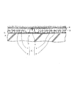
図1は、当該実施形態に係る植栽装置の一部断面図である。図において、Aは建造物の屋上のコンクリートスラブ面に貼着される防水層であり、この防水層Aの上面には、植物の毛根等の防水層への進出を防止するための樹脂製のルートガードBが張設されている。
Hereinafter, an embodiment of the present invention will be described with reference to the drawings.
FIG. 1 is a partial cross-sectional view of the planting apparatus according to the embodiment. In the figure, A is a waterproof layer adhered to the concrete slab surface of the roof of the building, and the upper surface of this waterproof layer A is made of resin for preventing entry into a waterproof layer such as a plant hair root. A root guard B is stretched.
Cは保水給排水手段としての樹脂または金属製の給・排水基盤で、全面にわたり保水部1と排水部2とが複数一体に形成されている。給・排水基盤Cの上部には種々の植物等が植立される客土層Dがその表面に防風ネットEを有して積層設置されている。そして、給・排水基盤Cは、一体に形成される保水部1と排水部2とを複数有るとともに前記防風ネットEの係止手段3を有し、この係止手段3は給・排水基盤Cの底部に形成した開口部とこの開口部に嵌合する中空体4とその有するブラケット部により構成されている。そして、防風ネットEは係止手段3等を介して屋上スラブ面の防水層Aに係止されるが、これについては更に後述する。
C is a water supply / drainage base made of resin or metal as water retention / drainage means, and a plurality of
図2に示すように、給・排水基盤Cの前記排水部2は、縦横に交叉連通して形成される通直管2aにより構成され、前記保水部1は各通直管2aにより囲繞されて形成される凹部空間により構成されている。
また、図3は給・排水基盤C上に適宜間隔で形成される前記係止手段3の構成を示す一部断面側面図である。 この係止手段3は、前述のように、給・排水基盤Cの底部に形成した開口部5とこの開口部5にそのブラケット部6が嵌合する中空体4とにより構成されている。すなわち、樹脂材またはアルミ材で形成される中空体4は円錐台形状をなしていて下端の周縁にはブラケット部6が一体に形成されている。 ブラケット部6は方形に形成されている。 一方、開口部5は、一辺が前記ブラケット部5よりやや大きく形成された方形を有しており、方形の各辺の周縁上方には傾斜面を有する立壁7が形成されている。 したがって、中空体4を開口部5の上方から投入することにより、中空体4のブラケット部6の端縁部は前記立壁7の傾斜面を滑落して開口部5において、ブラケット部6は容易に開口部5に嵌合するから作業効率は格段に向上する。
As shown in FIG. 2, the
FIG. 3 is a partial cross-sectional side view showing the structure of the locking means 3 formed on the water supply / drainage base C at appropriate intervals. As described above, the
さらに、図2、3において、通直管2aの交差部に形成される方形突部に設けた貫通小孔と中空体4の頂部形成した透孔により客土層に大気を循環させるための通気機構が構成され、大気が前記中空体、前記排水部、客土層を介して循環可能になる。
Further, in FIGS. 2 and 3, the ventilation for circulating the atmosphere to the soil layer through the small through holes provided in the rectangular protrusions formed at the intersection of the
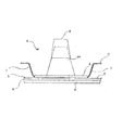
図4は、図3に示す状態から中空体4およびブラケット部6からなる前記係止手段3を開口部5に嵌合した状態を示す側面図である。図5において、中空体4は、外殻が円錐台形状の中空体である基部4aと同じく外殻円錐台形状の中空体である頂部8とから構成されている。頂部8の円錐度は基部4a
より急傾斜に設定され基部4aにきつく嵌合して容易には抜けないようになっている。客土層の種々の厚さに対応するため、高さの異なる頂部8を複数用意しておき、施工現場で頂部8の数を調整することにより客土層の厚さに適正に対応した係止手段3を簡単に設置することができる。なお、基部4a、頂部8それぞれの重ね合わせに際して、接着剤を塗布すればそれぞれは風の負圧に耐える強度を維持できるようになる。
FIG. 4 is a side view showing a state in which the locking means 3 including the
It is set to be steeper and is fitted tightly to the
次に、上記構成に係る給・排水基盤を使用しての屋上面における植栽装置の構築について説明する。
まず、図1において、防水層A表面に、構築しようとする植栽装置の形状面積に見合ったルートガードBを張設する。
次いで、前記ルートガードBの全面に両面接着テープTを貼り、表面の剥離シールをはがした上で、給・排水基盤Cを敷設してルートガードBに固定する。このとき、給・排水基盤Cにおける開口部5には前記両面接着テープTの粘着面が露出している、この状態で中空体4のブラケット部6の各辺を開口部5の各辺におおよそ対応させて中空体4を開口部5に押し込む。
すると、図3、図4に示すようにブラケット部6の端縁は開口部5の周縁に形成された立壁7の斜面を滑落するから、ブラケット部6は、図4に示すように開口部5に正確容易に合致した状態で接着テープTの粘着面に固定される。
Next, construction of a planting device on the roof surface using the water supply / drainage base according to the above configuration will be described.
First, in FIG. 1, the root guard B corresponding to the shape area of the planting device to be constructed is stretched on the surface of the waterproof layer A.
Next, a double-sided adhesive tape T is applied to the entire surface of the root guard B, the peel seal on the surface is peeled off, and then a water supply / drainage base C is laid and fixed to the root guard B. At this time, the adhesive surface of the double-sided adhesive tape T is exposed at the opening 5 in the water supply / drainage base C. In this state, each side of the
Then, as shown in FIGS. 3 and 4, the end edge of the
次いで、セットされた給・排水基盤C上に土壌を中空体4の高さにあわせて盛り込み客土層Dを形成する。 次いで、所望の植物の種子を撒布あるいは植物苗あるいはまた植物を客土層Dに定着させたうえで、防風ネットEを客土層D表面に設置する。 そして、防風ネットEをビス止めにより中空体4に係止する。客土層の厚さが、図4に示す中空体4の高さに適合するときはそのままで土を盛り込む。
客土層が図4の中空体4の高さより厚い場合には図5に示すように基部4aに適宜高さの頂部8を選択して基部4aに装着固定して係止手段3の高さ調整をなすことになる。
Next, the soil is put on the set water supply / drainage base C in accordance with the height of the
If the soil layer is thicker than the height of the
A.......防水層
B.......ルートガード
C.......給・排水基盤(保水給排水手段)
D.......客土層
1.......保水部
2.......排水部
2a......通直管
h.......通直管相互の交差部
3.......係止手段
4.......中空体
4a......基部
5.......開口部
6.......中空体のブラケット部
7.......開口部周縁における斜面を有する立壁
8.......頂部
A. . . . . . . Waterproof layer . . . . . . Root guard
C. . . . . . . Water supply / drainage base (water retention / drainage means)
D. . . . . . . Customer soil layer . . . . . .
Claims (3)
外殻が円錐台形状の中空体である基部と同じく外殻円錐台形状の中空体である頂部とから構成されるとともに、前記頂部の円錐度は前記基部より急傾斜に設定され基部にきつく嵌合して容易には抜けないが基部に対して着脱自在である ように構成したことを特徴とする係止手段。The outer shell is composed of a base that is a truncated cone-shaped hollow body and a top that is the outer shell-conical-shaped hollow body, and the conicity of the top is set to be steeper than the base and is tightly fitted to the base The locking means is configured so that it cannot be easily removed, but is detachable from the base.
Priority Applications (1)
| Application Number | Priority Date | Filing Date | Title |
|---|---|---|---|
| JP2005118104A JP4801369B2 (en) | 2005-04-15 | 2005-04-15 | Planting equipment and water supply / drainage base. |
Applications Claiming Priority (1)
| Application Number | Priority Date | Filing Date | Title |
|---|---|---|---|
| JP2005118104A JP4801369B2 (en) | 2005-04-15 | 2005-04-15 | Planting equipment and water supply / drainage base. |
Publications (3)
| Publication Number | Publication Date |
|---|---|
| JP2006296211A JP2006296211A (en) | 2006-11-02 |
| JP2006296211A5 JP2006296211A5 (en) | 2009-09-03 |
| JP4801369B2 true JP4801369B2 (en) | 2011-10-26 |
Family
ID=37465080
Family Applications (1)
| Application Number | Title | Priority Date | Filing Date |
|---|---|---|---|
| JP2005118104A Expired - Fee Related JP4801369B2 (en) | 2005-04-15 | 2005-04-15 | Planting equipment and water supply / drainage base. |
Country Status (1)
| Country | Link |
|---|---|
| JP (1) | JP4801369B2 (en) |
Families Citing this family (5)
| Publication number | Priority date | Publication date | Assignee | Title |
|---|---|---|---|---|
| JP4922786B2 (en) * | 2007-02-28 | 2012-04-25 | 田島緑化株式会社 | Planting equipment |
| JP2009142203A (en) * | 2007-12-14 | 2009-07-02 | Tajima Roofing Inc | Planting apparatus and method for structuring the apparatus |
| JP2009165406A (en) * | 2008-01-16 | 2009-07-30 | Tajima Roofing Inc | Planting device strengthening taking of plant root |
| JP2009195111A (en) * | 2008-02-19 | 2009-09-03 | Tajima Ryokka Kk | Planting device, water supply/drainage unit, and planting structure |
| JP2009278950A (en) * | 2008-05-26 | 2009-12-03 | Tajima Roofing Inc | Planting apparatus |
Family Cites Families (12)
| Publication number | Priority date | Publication date | Assignee | Title |
|---|---|---|---|---|
| JP3233877B2 (en) * | 1997-07-23 | 2001-12-04 | 田島ルーフィング株式会社 | Planting equipment |
| JP4068689B2 (en) * | 1997-07-24 | 2008-03-26 | 和志郎 林 | Connected structure |
| JPH1189688A (en) * | 1997-09-22 | 1999-04-06 | Minoru Uemura | Flowerpot stacking pole and flowerpot and water supply apparatus used therefor |
| JP3280912B2 (en) * | 1998-05-13 | 2002-05-13 | 田島ルーフィング株式会社 | Planting equipment |
| JP3403955B2 (en) * | 1998-10-29 | 2003-05-06 | 田島ルーフィング株式会社 | Seedling planting method and planting equipment used for it. |
| JP3581277B2 (en) * | 1999-09-14 | 2004-10-27 | 共同カイテック株式会社 | Plant cultivation container |
| JP2003088242A (en) * | 2001-09-17 | 2003-03-25 | Nagase & Co Ltd | Block for curb stone |
| JP4351426B2 (en) * | 2001-11-22 | 2009-10-28 | ロンシール工業株式会社 | Planting mat construction method |
| JP2003284428A (en) * | 2002-03-29 | 2003-10-07 | Aaki Yamade Kk | Planting installation structure |
| JP2004197476A (en) * | 2002-12-19 | 2004-07-15 | Yamato Plastic Kk | Brick-like building element |
| JP4097554B2 (en) * | 2003-04-01 | 2008-06-11 | 田島ルーフィング株式会社 | Planting equipment and drain pan. |
| JP2005073587A (en) * | 2003-09-01 | 2005-03-24 | Keylex Corp | Greening unit |
-
2005
- 2005-04-15 JP JP2005118104A patent/JP4801369B2/en not_active Expired - Fee Related
Also Published As
| Publication number | Publication date |
|---|---|
| JP2006296211A (en) | 2006-11-02 |
Similar Documents
| Publication | Publication Date | Title |
|---|---|---|
| JP5142498B2 (en) | Planting equipment and planting structure for plants | |
| JP2004503257A (en) | Modular green rooftop with panels with preferred edge system | |
| JP4801369B2 (en) | Planting equipment and water supply / drainage base. | |
| JP2006296211A5 (en) | ||
| JP4097554B2 (en) | Planting equipment and drain pan. | |
| KR100885004B1 (en) | Slim roof system for afforestation | |
| KR20100005980A (en) | Construction method of roof top greenization and structure thereof | |
| JP3280912B2 (en) | Planting equipment | |
| JP3581275B2 (en) | Planting equipment | |
| JP4417146B2 (en) | Greening method on artificial ground, greening structure and water retention drainage base material used there | |
| JP3286753B2 (en) | End treatment structure and end treatment member in planting equipment | |
| JP2003284428A (en) | Planting installation structure | |
| KR101238336B1 (en) | Greening structure | |
| JP3403955B2 (en) | Seedling planting method and planting equipment used for it. | |
| JP6719792B1 (en) | Agricultural house and construction method thereof | |
| JP2009195111A5 (en) | ||
| JP4922786B2 (en) | Planting equipment | |
| JP2009195111A (en) | Planting device, water supply/drainage unit, and planting structure | |
| JP5440980B2 (en) | Building surface greening method | |
| JPH03117434A (en) | Method for stabilizing tree in greening roof floor | |
| JP3328583B2 (en) | Nursery layer structure in planting equipment and nursery mat used for it | |
| JP5395420B2 (en) | Planting device and construction method | |
| JP2008206485A5 (en) | ||
| KR101238382B1 (en) | Medium box for roof garden and insulation | |
| EP4006252A1 (en) | System and method for covering buildings |
Legal Events
| Date | Code | Title | Description |
|---|---|---|---|
| A521 | Written amendment |
Free format text: JAPANESE INTERMEDIATE CODE: A523 Effective date: 20080408 |
|
| A621 | Written request for application examination |
Free format text: JAPANESE INTERMEDIATE CODE: A621 Effective date: 20080414 |
|
| A521 | Written amendment |
Free format text: JAPANESE INTERMEDIATE CODE: A523 Effective date: 20090716 |
|
| A977 | Report on retrieval |
Free format text: JAPANESE INTERMEDIATE CODE: A971007 Effective date: 20100428 |
|
| A131 | Notification of reasons for refusal |
Free format text: JAPANESE INTERMEDIATE CODE: A131 Effective date: 20110125 |
|
| A521 | Written amendment |
Free format text: JAPANESE INTERMEDIATE CODE: A523 Effective date: 20110218 |
|
| TRDD | Decision of grant or rejection written | ||
| A01 | Written decision to grant a patent or to grant a registration (utility model) |
Free format text: JAPANESE INTERMEDIATE CODE: A01 Effective date: 20110712 |
|
| A01 | Written decision to grant a patent or to grant a registration (utility model) |
Free format text: JAPANESE INTERMEDIATE CODE: A01 |
|
| A61 | First payment of annual fees (during grant procedure) |
Free format text: JAPANESE INTERMEDIATE CODE: A61 Effective date: 20110805 |
|
| FPAY | Renewal fee payment (event date is renewal date of database) |
Free format text: PAYMENT UNTIL: 20140812 Year of fee payment: 3 |
|
| R150 | Certificate of patent or registration of utility model |
Free format text: JAPANESE INTERMEDIATE CODE: R150 |
|
| LAPS | Cancellation because of no payment of annual fees |