JP4787630B2 - Ultrasonic probe - Google Patents
Ultrasonic probe Download PDFInfo
- Publication number
- JP4787630B2 JP4787630B2 JP2006057378A JP2006057378A JP4787630B2 JP 4787630 B2 JP4787630 B2 JP 4787630B2 JP 2006057378 A JP2006057378 A JP 2006057378A JP 2006057378 A JP2006057378 A JP 2006057378A JP 4787630 B2 JP4787630 B2 JP 4787630B2
- Authority
- JP
- Japan
- Prior art keywords
- filler
- piezoelectric
- acoustic
- matching layer
- ultrasonic probe
- Prior art date
- Legal status (The legal status is an assumption and is not a legal conclusion. Google has not performed a legal analysis and makes no representation as to the accuracy of the status listed.)
- Expired - Fee Related
Links
Images


Description
本発明は、複数の圧電素子を有する超音波探触子に関する。 The present invention relates to an ultrasonic probe having a plurality of piezoelectric elements.
生体内組織などに超音波を送受波して組織性状を観察する超音波診断装置が知られている。この超音波診断装置は、一般に、超音波探触子(プローブ)と装置本体によって構成される。そして、超音波探触子として、複数の振動素子(アレイ振動子)を備えたタイプの探触子が知られている(特許文献1,2参照)。 2. Description of the Related Art An ultrasonic diagnostic apparatus is known that transmits and receives ultrasonic waves to a tissue in a living body and observes tissue properties. This ultrasonic diagnostic apparatus is generally composed of an ultrasonic probe (probe) and an apparatus main body. As an ultrasonic probe, a type of probe having a plurality of vibration elements (array transducers) is known (see Patent Documents 1 and 2).
複数の振動素子を備えた超音波探触子は、バッキング上に複数の圧電素子が配置され、さらに複数の圧電素子の上に音響整合層が設けられる。そして、複数の圧電素子間の溝や音響整合層に設けられた溝に目詰め材料が充填され、これにより、音響クロストークの低減や素子耐久性の向上などが図られている。 In an ultrasonic probe including a plurality of vibration elements, a plurality of piezoelectric elements are arranged on a backing, and an acoustic matching layer is further provided on the plurality of piezoelectric elements. The grooves between the plurality of piezoelectric elements and the grooves provided in the acoustic matching layer are filled with a clogging material, thereby reducing acoustic crosstalk and improving element durability.
目詰め材料は、その音響インピーダンスが小さいほど音響クロストークの低減効果が高い。そのため、目詰め材料として、中空フィラーを混ぜたシリコーンゴムなどが利用されている。ちなみに、中空フィラーを混ぜたシリコーンゴムの音響インピーダンスは0.1〜0.3MRayls程度である。なお、M(メガ)Rayls=106kg/m2sである。 As the acoustic impedance of the plugging material is smaller, the effect of reducing acoustic crosstalk is higher. Therefore, silicone rubber mixed with a hollow filler is used as a filling material. Incidentally, the acoustic impedance of silicone rubber mixed with a hollow filler is about 0.1 to 0.3 MRayls. Note that M (mega) Rayls = 10 6 kg / m 2 s.
ところが、中空フィラーを混ぜたシリコーンゴムはその粘度が高くなり、そのため、例えば複数の圧電素子間の溝が狭い微細なアレイ振動子の場合に、目詰め材料を溝に埋め込む作業が困難になる。 However, the silicone rubber mixed with the hollow filler has a high viscosity, so that, for example, in the case of a fine array vibrator having a narrow groove between a plurality of piezoelectric elements, it is difficult to embed the filling material in the groove.
このように、音響クロストークの低減効果のみを意図すると、例えば微細なアレイ振動子を製造する場合などに、副作用的な問題が発生する。 Thus, if only the effect of reducing the acoustic crosstalk is intended, a side-effect problem occurs when, for example, a fine array transducer is manufactured.
本発明は、このような背景において成されたものであり、その目的は、音響クロストークの低減に関する改良技術を提供することにある。 The present invention has been made in such a background, and an object thereof is to provide an improved technique for reducing acoustic crosstalk.
上記目的を達成するために、本発明の好適な態様である超音波探触子は、バッキング層と、バッキング層上に設けられる圧電層と、圧電層上に設けられる整合層と、を有する超音波探触子であって、前記圧電層は、第一分割部によって複数に分割され、前記整合層は、第二分割部によって複数に分割され、前記第一分割部の音響インピーダンスは、前記第二分割部の音響インピーダンスよりも大きい、ことを特徴とする。 In order to achieve the above object, an ultrasonic probe according to a preferred embodiment of the present invention includes a backing layer, a piezoelectric layer provided on the backing layer, and a matching layer provided on the piezoelectric layer. In the acoustic probe, the piezoelectric layer is divided into a plurality of parts by a first dividing part, the matching layer is divided into a plurality of parts by a second dividing part, and the acoustic impedance of the first dividing part is It is characterized by being larger than the acoustic impedance of the bisection portion.
上記態様において、第一分割部は、複数に分割された圧電層の複数の分割片(圧電素子)間の音響クロストークを低減させる機能を担っている。このため、第一分割部の音響インピーダンスは、各圧電素子の音響インピーダンスよりも十分に小さいことが望ましい。また、第二分割部は、複数に分割された整合層の複数の分割片間の音響クロストークを低減させる機能を担っている。このため、第二分割部の音響インピーダンスは、整合層の音響インピーダンスよりも十分に小さいことが望ましい。さらに、上記態様では、第一分割部の音響インピーダンスが第二分割部の音響インピーダンスよりも大きい。これらを実現する具体例は、例えば、フィラー剤が添加されていないシリコーンゴムを溝に充填して第一分割部を形成し、フィラー剤が添加されたシリコーンゴムを溝に充填して第二分割部を形成する例である。 In the above aspect, the first division section has a function of reducing acoustic crosstalk between a plurality of divided pieces (piezoelectric elements) of the piezoelectric layer divided into a plurality. For this reason, it is desirable that the acoustic impedance of the first divided portion is sufficiently smaller than the acoustic impedance of each piezoelectric element. Moreover, the 2nd division part bears the function to reduce the acoustic crosstalk between several division pieces of the matching layer divided | segmented into plurality. For this reason, it is desirable that the acoustic impedance of the second divided portion is sufficiently smaller than the acoustic impedance of the matching layer. Furthermore, in the said aspect, the acoustic impedance of a 1st division part is larger than the acoustic impedance of a 2nd division part. Specific examples of realizing these are, for example, filling the groove with silicone rubber to which no filler agent is added to form the first divided portion, and filling the groove with silicone rubber to which the filler agent is added to form the second divided portion. It is an example which forms a part.
フィラー剤が添加されていないシリコーンゴムは、フィラー剤が添加されたシリコーンゴムに比べて、粘度が低くて流動性がある。したがって、例えば微細なアレイ振動子のように、複数の圧電素子間の溝が狭い場合でも、粘度が低い流動性を備えた材料を充填して第一分割部を形成することができる。これにより、粘度が高い材料を充填する場合に比べて材料の充填が容易になり、結果として、超音波探触子の製造が容易になる。 Silicone rubber to which no filler agent is added has lower viscosity and fluidity than silicone rubber to which a filler agent is added. Therefore, even when a groove between a plurality of piezoelectric elements is narrow, for example, like a fine array vibrator, the first divided portion can be formed by filling a material having fluidity with low viscosity. Thereby, the filling of the material is facilitated as compared with the case of filling the material having a high viscosity, and as a result, the manufacture of the ultrasonic probe is facilitated.
ちなみに、第一分割部と第二分割部の音響インピーダンスを具体的な数値で比較すると、第二分割部が例えば0〜0.3MRayls程度に形成され、第一分割部が例えば0.9〜3.0MRayls程度に形成される。第二分割部は、例えば、音響インピーダンスが0.3MRayls以下の材料(フィラー剤を添加したシリコーンゴムなど)を溝に充填することによって形成される。なお、溝に材料を充填することなく溝のみによって第二分割部を0MRaylsに形成してもよい。これに対して、第一分割部は、例えば、フィラー剤が添加されていないシリコーンゴムを溝に充填して形成される。なお、第一分割部の形成に利用されるシリコーンゴムは、フィラー剤が実質的に添加されていなければよい。つまり、粘度が低く流動性を保つ程度にフィラー剤が若干添加されてもよい。また、第一分割部の形成にウレタンなどを利用してもよい。 Incidentally, when the acoustic impedances of the first divided portion and the second divided portion are compared with specific numerical values, the second divided portion is formed to about 0 to 0.3 MRayls, for example, and the first divided portion is set to 0.9 to 3 for example. .About.0 MRayls. The second divided portion is formed, for example, by filling the groove with a material having an acoustic impedance of 0.3 MRayls or less (such as silicone rubber with a filler added). In addition, you may form a 2nd division part in 0MRRays only by a groove | channel, without filling a groove | channel with a material. On the other hand, the first divided portion is formed, for example, by filling the groove with silicone rubber to which no filler agent is added. In addition, the silicone rubber utilized for formation of a 1st division | segmentation part does not need to be substantially added with the filler agent. That is, a filler agent may be added to such an extent that the viscosity is low and fluidity is maintained. Moreover, you may utilize urethane etc. for formation of a 1st division part.
望ましい態様において、前記圧電層は、第一分割部として機能する溝によって複数に分割され、前記整合層は、第二分割部として機能する溝によって複数に分割される、ことを特徴とする。望ましい態様において、前記圧電層の溝には、第一充填剤が充填され、前記整合層の溝には、第二充填剤が充填され、前記第一充填剤の音響インピーダンスは、前記第二充填剤の音響インピーダンスよりも大きい、ことを特徴とする。望ましい態様において、前記第一充填剤は、フィラー剤が実質的に添加されていない充填剤であり、前記第二充填剤は、フィラー剤が添加された充填剤である、ことを特徴とする。望ましい態様において、前記第一充填剤は、フィラー剤が添加されていないシリコーンゴムである、ことを特徴とする。 In a preferred aspect, the piezoelectric layer is divided into a plurality of grooves functioning as first divided parts, and the matching layer is divided into a plurality of grooves functioning as second divided parts. In a preferred embodiment, the groove of the piezoelectric layer is filled with a first filler, the groove of the matching layer is filled with a second filler, and the acoustic impedance of the first filler is the second filling. It is characterized by being larger than the acoustic impedance of the agent. In a preferred aspect, the first filler is a filler to which a filler agent is not substantially added, and the second filler is a filler to which a filler agent is added. In a preferred embodiment, the first filler is silicone rubber to which no filler agent is added.
また、上記目的を達成するために、本発明の好適な態様である超音波探触子の製造方法は、バッキング上に電極を介して圧電板を接着する工程と、圧電板をカットして複数に分割する工程と、カットによって圧電板に形成された分割溝に第一充填剤を充填する工程と、圧電板上に電極を介して音響整合層を接着する工程と、音響整合層をカットして複数に分割する工程と、カットによって音響整合層に形成された分割溝に第二充填剤を充填する工程と、を含み、前記第一充填剤を充填する工程において、前記第二充填剤よりも音響インピーダンスが大きい第一充填剤が充填される、ことを特徴とする。 In order to achieve the above object, an ultrasonic probe manufacturing method according to a preferred embodiment of the present invention includes a step of bonding a piezoelectric plate through an electrode on a backing, a plurality of piezoelectric plates by cutting the piezoelectric plate. Cutting the acoustic matching layer, cutting the acoustic matching layer, filling the first groove with a first filler, cutting the acoustic matching layer through an electrode, and cutting the acoustic matching layer. A step of filling the first filler with the second filler, and a step of filling the divided grooves formed in the acoustic matching layer by cutting with a second filler. Is also filled with a first filler having a high acoustic impedance.
望ましい態様において、前記製造方法は、カットによって複数に分割された圧電板の上面をマスキングシートで保護する工程をさらに含み、前記第一充填剤を充填する工程において、マスキングシートで上面を保護された圧電板の側面から分割溝に第一充填剤が充填される、ことを特徴とする。 In a preferred aspect, the manufacturing method further includes a step of protecting an upper surface of the piezoelectric plate divided into a plurality of parts by cutting with a masking sheet, and the upper surface is protected with the masking sheet in the step of filling the first filler. The first filler is filled into the dividing groove from the side surface of the piezoelectric plate.
本発明により、超音波探触子の音響クロストーク低減に関する改良技術が提供される。 The present invention provides an improved technique for reducing acoustic crosstalk in an ultrasound probe.
以下、本発明の好適な実施形態を説明する。 Hereinafter, preferred embodiments of the present invention will be described.
図1には、本発明に係る超音波探触子の好適な実施形態が示されており、図1はその振動子部分の構成図である。 FIG. 1 shows a preferred embodiment of an ultrasonic probe according to the present invention, and FIG. 1 is a configuration diagram of a transducer portion thereof.
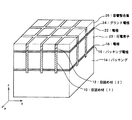
図1に示す超音波探触子(振動子部分)は、バッキング14と、バッキング14上に設けられる複数の圧電素子20と、複数の圧電素子20上に設けられる音響整合層26を備えている。つまり、z軸の正方向に向かって、バッキング14と圧電素子20と音響整合層26を積層した構造である。 The ultrasonic probe (vibrator portion) shown in FIG. 1 includes a backing 14, a plurality of piezoelectric elements 20 provided on the backing 14, and an acoustic matching layer 26 provided on the plurality of piezoelectric elements 20. . That is, the backing 14, the piezoelectric element 20, and the acoustic matching layer 26 are stacked in the positive direction of the z axis.
なお、圧電素子20は、その上下から、つまりz軸方向の正方向側と負方向側から、二枚の電極22と電極18によって挟まれており、さらに、電極18とバッキング14との間にはバッキング電極16が挿入され、電極22と音響整合層26との間にはグランド電極24が挿入されている。 The piezoelectric element 20 is sandwiched between the two electrodes 22 and 18 from above and below, that is, from the positive side and the negative side in the z-axis direction, and further between the electrode 18 and the backing 14. A backing electrode 16 is inserted, and a ground electrode 24 is inserted between the electrode 22 and the acoustic matching layer 26.
各圧電素子20は略四角柱状に形成され、そして複数の圧電素子20がx方向とy方向に2次元的に配列されている。ちなみに、図1においてはx方向に4個でy方向に3個の合計12個の圧電素子20を示しているが、圧電素子20の個数は12個に限定されるものではなく、超音波探触子の用途などに応じて適宜設定される。 Each piezoelectric element 20 is formed in a substantially quadrangular prism shape, and a plurality of piezoelectric elements 20 are two-dimensionally arranged in the x direction and the y direction. Incidentally, although FIG. 1 shows a total of twelve piezoelectric elements 20, four in the x direction and three in the y direction, the number of piezoelectric elements 20 is not limited to twelve. It is appropriately set according to the use of the touch element.
各圧電素子20は、バッキング14内に形成された図示しないリード線に電気的に接続される。つまり、バッキング14内には、複数の圧電素子20の各々に対応したリード線が設けられており、さらに、各リード線が複数のバッキング電極16の各々に接続されている。そして、各圧電素子20の電極18がその圧電素子20に対応したバッキング電極16に電気的に接続され、これにより、各圧電素子20とそれに対応したリード線が電気的に接続される。また、各圧電素子20は、それに対応した電極22を介してグランド電極24に電気的に接続されている。 Each piezoelectric element 20 is electrically connected to a lead wire (not shown) formed in the backing 14. That is, lead wires corresponding to each of the plurality of piezoelectric elements 20 are provided in the backing 14, and each lead wire is connected to each of the plurality of backing electrodes 16. Then, the electrode 18 of each piezoelectric element 20 is electrically connected to the backing electrode 16 corresponding to the piezoelectric element 20, thereby electrically connecting each piezoelectric element 20 and the corresponding lead wire. Each piezoelectric element 20 is electrically connected to the ground electrode 24 via the corresponding electrode 22.
このような構成の各圧電素子20は、リード線を介して電極18と電極22との間に電圧が印加されることにより振動して超音波を発生する。また、各圧電素子20が超音波(反射波)を受波して振動することにより発生する電極18と電極22との間の電圧がリード線を介して検出される。 Each piezoelectric element 20 having such a configuration vibrates and generates ultrasonic waves when a voltage is applied between the electrode 18 and the electrode 22 via a lead wire. Further, the voltage between the electrode 18 and the electrode 22 generated when each piezoelectric element 20 receives an ultrasonic wave (reflected wave) and vibrates is detected via a lead wire.
音響整合層26は、複数の圧電素子20に対応して複数に分割されている。つまり、音響整合層26は、x方向とy方向に2次元的に分割され、音響整合層26の各分割片が各圧電素子20に対応している。音響整合層26は、被検体(生体)と圧電素子20との間の音響インピーダンス整合をとり、これにより、圧電素子20から被検体へ超音波が効率的に伝達され、また、被検体から圧電素子20へ反射波が効率的に伝達される。 The acoustic matching layer 26 is divided into a plurality of parts corresponding to the plurality of piezoelectric elements 20. That is, the acoustic matching layer 26 is two-dimensionally divided in the x direction and the y direction, and each divided piece of the acoustic matching layer 26 corresponds to each piezoelectric element 20. The acoustic matching layer 26 performs acoustic impedance matching between the subject (living body) and the piezoelectric element 20, whereby ultrasonic waves are efficiently transmitted from the piezoelectric element 20 to the subject, and the piezoelectric from the subject is piezoelectric. The reflected wave is efficiently transmitted to the element 20.
なお、バッキング14は、例えば剛性の高い合成樹脂などで形成され、圧電素子20から下方側、つまりz軸の負方向側へ放射される超音波を吸収している。これにより、圧電素子20で発生される振動(超音波)のエネルギーが音響整合層26側へ効率よく伝達される。 The backing 14 is made of, for example, a highly rigid synthetic resin and absorbs ultrasonic waves radiated from the piezoelectric element 20 downward, that is, in the negative direction of the z axis. Thereby, the energy of the vibration (ultrasound) generated by the piezoelectric element 20 is efficiently transmitted to the acoustic matching layer 26 side.
さらに、本実施形態では、複数の圧電素子20の間に形成された溝に目詰め材(1)10が充填され、また、音響整合層26に形成された溝に目詰め材(2)12が充填されている。 Further, in the present embodiment, the filling material (1) 10 is filled in the groove formed between the plurality of piezoelectric elements 20, and the filling material (2) 12 is filled in the groove formed in the acoustic matching layer 26. Is filled.
目詰め材(1)10は、複数の圧電素子20間の音響クロストークを低減させる機能を担っている。このため、目詰め材(1)10の音響インピーダンスは、各圧電素子20の音響インピーダンスとの差が大きいことが望ましい。本実施形態では、目詰め材(1)10の音響インピーダンスが、各圧電素子20の音響インピーダンスよりも十分に小さく設定されている。 The packing material (1) 10 has a function of reducing acoustic crosstalk between the plurality of piezoelectric elements 20. For this reason, it is desirable that the acoustic impedance of the packing material (1) 10 has a large difference from the acoustic impedance of each piezoelectric element 20. In the present embodiment, the acoustic impedance of the packing material (1) 10 is set to be sufficiently smaller than the acoustic impedance of each piezoelectric element 20.
各圧電素子20は、チタン酸ジルコン酸鉛(PZT)などの圧電セラミックスで形成され、その音響インピーダンスは、22〜30MRayls程度である。PZTに複合材を混ぜることにより、音響インピーダンスの範囲が例えば15〜30MRayls程度の圧電素子20を形成してもよい。 Each piezoelectric element 20 is made of piezoelectric ceramics such as lead zirconate titanate (PZT), and its acoustic impedance is about 22 to 30 MRayls. The piezoelectric element 20 having an acoustic impedance range of, for example, about 15 to 30 MRayls may be formed by mixing a composite material with PZT.
これに対し、目詰め材(1)10の音響インピーダンスは、各圧電素子20の音響インピーダンスよりも十分に小さく設定される。目詰め材(1)10は、フィラー剤が添加されていない充填剤であり、その音響インピーダンスは、0.9〜3.0MRayls程度に形成される。例えば、フィラー剤が添加されていないシリコーンゴムやウレタンなどを利用して0.9〜3.0MRayls程度の音響インピーダンスが実現される。このように、目詰め材(1)10の音響インピーダンス(0.9〜3.0MRayls程度)は、各圧電素子20の音響インピーダンス(22〜30MRayls程度)よりも十分小さい値に設定される。 On the other hand, the acoustic impedance of the packing material (1) 10 is set sufficiently smaller than the acoustic impedance of each piezoelectric element 20. The packing material (1) 10 is a filler to which a filler agent is not added, and its acoustic impedance is formed to about 0.9 to 3.0 MRayls. For example, an acoustic impedance of about 0.9 to 3.0 MRayls is realized by using silicone rubber or urethane to which no filler agent is added. Thus, the acoustic impedance (about 0.9 to 3.0 MRayls) of the packing material (1) 10 is set to a value sufficiently smaller than the acoustic impedance of each piezoelectric element 20 (about 22 to 30 MRayls).
目詰め材(1)10の音響インピーダンスを0.9〜3.0MRaylsとし、各圧電素子20の音響インピーダンスを22〜30MRaylsとして、各圧電素子20と目詰め材(1)10の間の超音波の透過率を計算すると、5.8〜24パーセントとなり、複数の圧電素子20間の音響クロストークを十分に低減させることがわかる。なお、目詰め材(1)10は、フィラー剤が添加されないことにより、その粘度が低く流動性を備えているため、複数の圧電素子20の隙間が狭い場合であっても、その隙間に充填しやすいという効果を奏する。これについては、後に詳述する。 Ultrasonic waves between each piezoelectric element 20 and the packing material (1) 10 with the acoustic impedance of the packing material (1) 10 being 0.9 to 3.0 MRayls and the acoustic impedance of each piezoelectric element 20 being 22 to 30 MRayls. When the transmissivity is calculated, it becomes 5.8 to 24%, and it can be seen that the acoustic crosstalk between the plurality of piezoelectric elements 20 is sufficiently reduced. The filling material (1) 10 has a low viscosity and fluidity because no filler agent is added. Therefore, even when the gaps of the plurality of piezoelectric elements 20 are narrow, the gaps are filled. The effect is easy to do. This will be described in detail later.
目詰め材(2)12は、複数に分割された音響整合層26の複数の分割片間の音響クロストークを低減させる機能を担っている。このため、目詰め材(2)12の音響インピーダンスは、音響整合層26の音響インピーダンスとの差が大きいことが望ましい。本実施形態では、目詰め材(2)12の音響インピーダンスが、音響整合層26の音響インピーダンスよりも十分に小さく設定されている。 The packing material (2) 12 has a function of reducing acoustic crosstalk between a plurality of divided pieces of the acoustic matching layer 26 divided into a plurality. For this reason, it is desirable that the acoustic impedance of the packing material (2) 12 has a large difference from the acoustic impedance of the acoustic matching layer 26. In the present embodiment, the acoustic impedance of the packing material (2) 12 is set to be sufficiently smaller than the acoustic impedance of the acoustic matching layer 26.
音響整合層26は、例えばエポキシ樹脂などを利用して形成され、必要に応じて多層構造として段階的な整合を実現することにより、その音響インピーダンスは、例えば2〜12MRayls程度に形成される。これに対し、目詰め材(2)12の音響インピーダンスは、音響整合層26の音響インピーダンスよりも十分に小さく設定される。目詰め材(2)12は、フィラー剤が添加された充填剤であり、その音響インピーダンスは、例えば0〜0.3MRayls程度である。例えば、フィラー剤を添加したシリコーンゴムによって0.3MRayls程度の音響インピーダンスが実現できる。なお、音響整合層26の溝に材料を充填することなく溝のみによって0MRayls程度の音響インピーダンスを実現してもよい。 The acoustic matching layer 26 is formed using, for example, an epoxy resin, and the acoustic impedance thereof is formed to about 2 to 12 MRayls, for example, by realizing stepwise matching as a multilayer structure as necessary. On the other hand, the acoustic impedance of the packing material (2) 12 is set to be sufficiently smaller than the acoustic impedance of the acoustic matching layer 26. The filling material (2) 12 is a filler to which a filler agent is added, and its acoustic impedance is, for example, about 0 to 0.3 MRayls. For example, an acoustic impedance of about 0.3 MRayls can be realized with silicone rubber to which a filler agent is added. Note that an acoustic impedance of about 0 MRayls may be realized only by the groove without filling the groove of the acoustic matching layer 26 with a material.
なお、目詰め材(2)12の音響インピーダンスを0〜0.3MRaylsとし、音響整合層26の音響インピーダンスを2〜12MRaylsとして、音響整合層26と目詰め材(2)12の間の超音波の透過率を計算すると、0〜26パーセントとなり、十分な音響クロストークの低減効果が得られる。 Note that the acoustic impedance of the packing material (2) 12 is 0 to 0.3 MRayls, the acoustic impedance of the acoustic matching layer 26 is 2 to 12 MRayls, and the ultrasonic waves between the acoustic matching layer 26 and the plugging material (2) 12 are used. When the transmittance is calculated, it becomes 0 to 26%, and a sufficient acoustic crosstalk reduction effect is obtained.
ちなみに、超音波が音響インピーダンスZ1の材料から音響インピーダンスZ2の材料へ伝播する際の透過率は、(2×Z2)/(Z1+Z2)で計算される。 Incidentally, the transmittance when the ultrasonic wave propagates from the material having the acoustic impedance Z 1 to the material having the acoustic impedance Z 2 is calculated by (2 × Z 2 ) / (Z 1 + Z 2 ).
次に、本発明に係る超音波探触子の製造方法について説明する。 Next, a method for manufacturing the ultrasonic probe according to the present invention will be described.
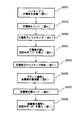
図2は、本発明に係る超音波探触子の製造方法を説明するための図であり、図1の超音波探触子の製造工程を示すフローチャートである。また、図3から図9には、各工程ごとの超音波探触子(振動子部分)の形成状態が示されている。以下、図3から図9を参照しながら、図2のフローチャートの各ステップごとにその処理内容を説明する。 FIG. 2 is a diagram for explaining a method of manufacturing the ultrasonic probe according to the present invention, and is a flowchart showing manufacturing steps of the ultrasonic probe of FIG. FIGS. 3 to 9 show the formation state of the ultrasonic probe (vibrator portion) for each step. Hereinafter, the processing content will be described for each step of the flowchart of FIG. 2 with reference to FIGS.
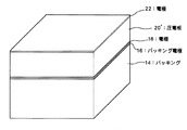
<S201(図3)>まず、バッキング14上に圧電板20´が接着される。なお、バッキング14の上面には予めバッキング電極16が形成されており、圧電板20´の上下面には予め電極18と電極22が形成されている。また、バッキング14内には、後に形成される複数の圧電素子の各々に対応したリード線(図示せず)が設けられている。 <S201 (FIG. 3)> First, the piezoelectric plate 20 'is bonded onto the backing 14. A backing electrode 16 is formed in advance on the upper surface of the backing 14, and an electrode 18 and an electrode 22 are formed in advance on the upper and lower surfaces of the piezoelectric plate 20 '. Further, lead wires (not shown) corresponding to each of a plurality of piezoelectric elements to be formed later are provided in the backing 14.
<S202(図4)>次に、圧電板がカットされて複数の圧電素子20が形成される。つまり、圧電板が碁盤目状にカットされて切り溝32によって分割され、格子状に配列された複数の圧電素子20が形成される。なお、バッキング電極16、電極18、電極22も圧電板のカットに伴って分割され、各圧電素子20ごとにそれに対応したバッキング電極16、電極18、電極22が形成される。 <S202 (FIG. 4)> Next, the piezoelectric plate is cut to form a plurality of piezoelectric elements 20. In other words, the piezoelectric plate is cut in a grid pattern and divided by the kerfs 32 to form a plurality of piezoelectric elements 20 arranged in a lattice pattern. The backing electrode 16, the electrode 18, and the electrode 22 are also divided along with the cutting of the piezoelectric plate, and the backing electrode 16, the electrode 18, and the electrode 22 corresponding to each piezoelectric element 20 are formed.
<S203(図5)>次に、複数の圧電素子20の上面にマスキングシート34が載せられる。後の工程において、圧電素子20の上面にグランド電極が接着されるため、このマスキングシート34によって、圧電素子20の表面が保護される。 <S203 (FIG. 5)> Next, the masking sheet 34 is placed on the upper surfaces of the plurality of piezoelectric elements 20. In the subsequent process, since the ground electrode is bonded to the upper surface of the piezoelectric element 20, the surface of the piezoelectric element 20 is protected by the masking sheet 34.
<S204(図6)>次に、複数の圧電素子20の側面から切り溝(図5の符号32)内に目詰め材(1)10が充填される。目詰め材(1)10としては、先述のように、例えば、フィラー剤が添加されていないシリコーンゴムやウレタンが利用される。フィラー剤が添加されていないシリコーンゴムなどは、フィラー剤が添加されたシリコーンゴムなどに比べて、粘度が低くて流動性がある。したがって、例えば微細なアレイ振動子のように、複数の圧電素子20の間の溝が狭い場合でも、粘度が低い流動性を備えた目詰め材(1)10を側面から充填することができる。なお、目詰め材(1)10として利用されるシリコーンゴムなどは、フィラー剤が実質的に添加されていなければよい。つまり、粘度が低く流動性を保つ程度にフィラー剤が若干添加されてもよい。 <S204 (FIG. 6)> Next, the filling material (1) 10 is filled into the cut grooves (reference numeral 32 in FIG. 5) from the side surfaces of the plurality of piezoelectric elements 20. As the filling material (1) 10, as described above, for example, silicone rubber or urethane to which a filler agent is not added is used. Silicone rubber or the like to which no filler agent is added has a lower viscosity and fluidity than silicone rubber or the like to which a filler agent has been added. Accordingly, even when the grooves between the plurality of piezoelectric elements 20 are narrow, for example, like a fine array vibrator, the packing material (1) 10 having fluidity with low viscosity can be filled from the side surface. In addition, the silicone rubber etc. utilized as the filling material (1) 10 do not need to be substantially added with a filler agent. That is, a filler agent may be added to such an extent that the viscosity is low and fluidity is maintained.
<S205(図7)>目詰め材(1)10の充填後、マスキングシート(図6の符号34)が取り除かれる。前工程のS204において、仮に、マスキングシートによって圧電素子20の上面が保護されていないと、圧電素子20の上面に目詰め材(1)10が付着して電極22が汚染されてしまう可能性がある。しかし、前工程のS204では、マスキングシートによって圧電素子20の上面が保護された状態で目詰め材(1)10が充填されているため、目詰め材(1)10の充填後にマスキングシートが取り除かれると、マスキングシートによって保護されていた汚染されていない電極22が現れる。 <S205 (FIG. 7)> After the filling material (1) 10 is filled, the masking sheet (reference numeral 34 in FIG. 6) is removed. In the previous step S204, if the upper surface of the piezoelectric element 20 is not protected by the masking sheet, the packing material (1) 10 may adhere to the upper surface of the piezoelectric element 20 and the electrode 22 may be contaminated. is there. However, in the previous step S204, the filling material (1) 10 is filled with the masking sheet protecting the upper surface of the piezoelectric element 20, and therefore the masking sheet is removed after filling the filling material (1) 10. As a result, an uncontaminated electrode 22 protected by the masking sheet appears.
<S206(図8)>次に、電極22上にグランド電極24が接着され、さらにグランド電極24上に音響整合層26が接着される。なお、音響整合層26は複数の層で構成されてもよい。 <S206 (FIG. 8)> Next, the ground electrode 24 is bonded onto the electrode 22, and the acoustic matching layer 26 is bonded onto the ground electrode 24. The acoustic matching layer 26 may be composed of a plurality of layers.
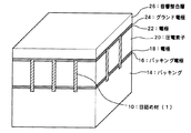
<S207(図9)>次に、音響整合層26がカットされて複数に分割される。つまり、音響整合層26が、複数の圧電素子20に合わせて切り溝36によって碁盤目状に分割される。なお、この工程においてグランド電極24はカットされない。 <S207 (FIG. 9)> Next, the acoustic matching layer 26 is cut and divided into a plurality of parts. That is, the acoustic matching layer 26 is divided into a grid pattern by the kerfs 36 according to the plurality of piezoelectric elements 20. In this step, the ground electrode 24 is not cut.
<S208(図1)>最後に、音響整合層26の切り溝36(図9の符号36)内に目詰め材(2)12が充填される。目詰め材(2)12としては、先述のように、例えば、フィラー剤が添加されたシリコーンゴムやウレタンなどが利用される。目詰め材(2)12を十分に挿入するために、例えばへらなどが利用されて、切り溝36内に目詰め材(2)12が充填される。これにより、目詰め材(2)12に添加されたフィラー剤(中空フィラーなど)も満遍なく切り溝36内に挿入される。こうして、図1に示す超音波探触子(振動子部分)が形成される。 <S208 (FIG. 1)> Finally, the filling material (2) 12 is filled into the kerf 36 (reference numeral 36 in FIG. 9) of the acoustic matching layer 26. As the filling material (2) 12, as described above, for example, silicone rubber or urethane to which a filler agent is added is used. In order to fully insert the packing material (2) 12, for example, a spatula or the like is used to fill the packing material (2) 12 into the kerf 36. Thereby, the filler agent (hollow filler etc.) added to the filling material (2) 12 is also inserted in the cut groove 36 uniformly. Thus, the ultrasonic probe (vibrator portion) shown in FIG. 1 is formed.
以上、本発明の好適な実施形態を説明したが、上述した実施形態は、次のような格別な効果を奏する。 As mentioned above, although preferred embodiment of this invention was described, embodiment mentioned above has the following special effects.
図1に示す構成において、目詰め材(1)10の音響インピーダンスは圧電素子20の音響インピーダンスに対して十分に小さいため、複数の圧電素子20間の音響クロストークが小さくなる。また、目詰め材(2)12の音響インピーダンスは音響整合層26の音響インピーダンスに対して十分に小さいため、分割された音響整合層26間の音響クロストークが小さくなる。これにより、指向角特性の良い超音波探触子を製造することができる。 In the configuration shown in FIG. 1, the acoustic impedance of the packing material (1) 10 is sufficiently smaller than the acoustic impedance of the piezoelectric element 20, so that the acoustic crosstalk between the plurality of piezoelectric elements 20 is reduced. Moreover, since the acoustic impedance of the packing material (2) 12 is sufficiently smaller than the acoustic impedance of the acoustic matching layer 26, the acoustic crosstalk between the divided acoustic matching layers 26 is reduced. Thereby, an ultrasonic probe with good directivity angle characteristics can be manufactured.
また、目詰め材(1)10を粘度が低い流動性を備えた材料としたことにより、圧電素子20の側面から切り溝内に十分に目詰め材(1)10を行き渡らせることが可能になり、これにより、目詰め材のむらがなくなり、複数の圧電素子20の特性を均一にすることができる。また、充填作業も容易になり作業性が向上する。ちなみに、目詰め材(1)10にフィラー剤を添加しないことにより、音響インピーダンスを従来のものに比べて大きくすることで、圧電素子20の耐久性も向上する。 In addition, since the packing material (1) 10 is made of a material having low viscosity and fluidity, the packing material (1) 10 can be sufficiently distributed from the side surface of the piezoelectric element 20 into the cut groove. Thus, the unevenness of the packing material is eliminated, and the characteristics of the plurality of piezoelectric elements 20 can be made uniform. In addition, the filling operation is facilitated and the workability is improved. Incidentally, the durability of the piezoelectric element 20 is also improved by increasing the acoustic impedance compared to the conventional one by not adding a filler agent to the packing material (1) 10.
以上、本発明の好適な実施形態を説明したが、上述した実施形態はあらゆる点で単なる例示にすぎず、本発明の範囲を限定するものではない。 As mentioned above, although preferred embodiment of this invention was described, embodiment mentioned above is only a mere illustration in all the points, and does not limit the scope of the present invention.
10 目詰め材(1)、12 目詰め材(2)、20 圧電素子、26 音響整合層。
10 packing material (1), 12 packing material (2), 20 piezoelectric element, 26 acoustic matching layer.
Claims (3)
バッキング層上に設けられる圧電層と、
圧電層上に設けられる整合層と、
を有する超音波探触子であって、
前記圧電層は、第一分割部として機能する溝によって複数に分割され、
前記整合層は、第二分割部として機能する溝によって複数に分割され、
前記圧電層の溝には、第一充填剤が充填され、
前記整合層の溝には、第二充填剤が充填され、
前記第一充填剤の音響インピーダンスは、前記第二充填剤の音響インピーダンスよりも大きく、
前記第一充填剤は、フィラー剤が実質的に添加されていない充填剤であり、
前記第二充填剤は、フィラー剤が添加された充填剤である、
ことを特徴とする超音波探触子。 Backing layer,
A piezoelectric layer provided on the backing layer;
A matching layer provided on the piezoelectric layer;
An ultrasonic probe comprising:
The piezoelectric layer is divided into a plurality of grooves functioning as a first divided portion,
The matching layer is divided into a plurality of grooves functioning as a second divided portion,
The groove of the piezoelectric layer is filled with a first filler,
The groove of the matching layer is filled with a second filler,
The acoustic impedance of the first filler is greater than the acoustic impedance of the second filler,
The first filler is a filler to which a filler agent is not substantially added,
The second filler is a filler to which a filler agent is added,
An ultrasonic probe characterized by that.
前記第一充填剤は、フィラー剤が添加されていないシリコーンゴムである、
ことを特徴とする超音波探触子。 The ultrasonic probe according to claim 1 ,
The first filler is a silicone rubber to which no filler agent is added.
An ultrasonic probe characterized by that.
圧電板をカットして複数に分割する工程と、
カットによって圧電板に形成された分割溝に第一充填剤を充填する工程と、
圧電板上に電極を介して音響整合層を接着する工程と、
音響整合層をカットして複数に分割する工程と、
カットによって音響整合層に形成された分割溝に第二充填剤を充填する工程と、
を含み、
前記第一充填剤を充填する工程において、フィラー剤が実質的に添加されていない第一充填剤が充填されることを特徴とし、
カットによって複数に分割された圧電板の上面をマスキングシートで保護する工程をさらに含み、
前記第一充填剤を充填する工程において、マスキングシートで上面を保護された圧電板の側面から分割溝に第一充填剤が充填される、
ことを特徴とする超音波探触子の製造方法。
Bonding the piezoelectric plate on the backing via an electrode;
Cutting the piezoelectric plate into a plurality of parts,
Filling the first groove into the dividing grooves formed on the piezoelectric plate by cutting;
Bonding an acoustic matching layer on the piezoelectric plate via an electrode;
Cutting the acoustic matching layer into a plurality of parts,
Filling the dividing groove formed in the acoustic matching layer by cutting with a second filler;
Including
In the step of filling the first filler, the first filler to which a filler agent is not substantially added is filled ,
Further comprising a step of protecting the upper surface of the piezoelectric plate divided into a plurality by cutting with a masking sheet,
In the step of filling the first filler, the first filler is filled from the side surface of the piezoelectric plate whose upper surface is protected by the masking sheet,
An ultrasonic probe manufacturing method characterized by the above.
Priority Applications (1)
| Application Number | Priority Date | Filing Date | Title |
|---|---|---|---|
| JP2006057378A JP4787630B2 (en) | 2006-03-03 | 2006-03-03 | Ultrasonic probe |
Applications Claiming Priority (1)
| Application Number | Priority Date | Filing Date | Title |
|---|---|---|---|
| JP2006057378A JP4787630B2 (en) | 2006-03-03 | 2006-03-03 | Ultrasonic probe |
Publications (2)
| Publication Number | Publication Date |
|---|---|
| JP2007235795A JP2007235795A (en) | 2007-09-13 |
| JP4787630B2 true JP4787630B2 (en) | 2011-10-05 |
Family
ID=38555882
Family Applications (1)
| Application Number | Title | Priority Date | Filing Date |
|---|---|---|---|
| JP2006057378A Expired - Fee Related JP4787630B2 (en) | 2006-03-03 | 2006-03-03 | Ultrasonic probe |
Country Status (1)
| Country | Link |
|---|---|
| JP (1) | JP4787630B2 (en) |
Families Citing this family (12)
| Publication number | Priority date | Publication date | Assignee | Title |
|---|---|---|---|---|
| EP2091265A4 (en) | 2006-11-08 | 2010-12-15 | Hitachi Medical Corp | Ultrasonic probe and ultrasonographic device using the same |
| JP4386109B2 (en) | 2007-07-11 | 2009-12-16 | 株式会社デンソー | Ultrasonic sensor and method for manufacturing ultrasonic sensor |
| JP5659564B2 (en) * | 2010-06-10 | 2015-01-28 | コニカミノルタ株式会社 | Ultrasonic probe and ultrasonic diagnostic apparatus |
| JP5699690B2 (en) * | 2011-03-03 | 2015-04-15 | コニカミノルタ株式会社 | Manufacturing method of ultrasonic probe |
| JP5692042B2 (en) * | 2011-12-16 | 2015-04-01 | コニカミノルタ株式会社 | Piezoelectric cell, piezoelectric element, ultrasonic probe, and ultrasonic diagnostic apparatus |
| JP6273743B2 (en) | 2013-09-30 | 2018-02-07 | セイコーエプソン株式会社 | Ultrasonic device and probe, electronic apparatus and ultrasonic imaging apparatus |
| JP6442821B2 (en) | 2013-09-30 | 2018-12-26 | セイコーエプソン株式会社 | Ultrasonic device and electronic equipment |
| JP6252248B2 (en) * | 2014-02-27 | 2017-12-27 | セイコーエプソン株式会社 | Ultrasonic device, manufacturing method thereof, probe, electronic apparatus, and ultrasonic imaging apparatus |
| JP6299509B2 (en) | 2014-07-31 | 2018-03-28 | セイコーエプソン株式会社 | Ultrasonic device and probe, electronic apparatus and ultrasonic imaging apparatus |
| JP6641723B2 (en) * | 2015-05-08 | 2020-02-05 | コニカミノルタ株式会社 | Ultrasonic transducer and manufacturing method thereof, ultrasonic probe, and ultrasonic imaging apparatus |
| US10797221B2 (en) * | 2017-02-24 | 2020-10-06 | Baker Hughes, A Ge Company, Llc | Method for manufacturing an assembly for an ultrasonic probe |
| CN110227640B (en) * | 2019-06-18 | 2021-01-26 | 京东方科技集团股份有限公司 | Piezoelectric sensor assembly, manufacturing method thereof and display panel |
Family Cites Families (4)
| Publication number | Priority date | Publication date | Assignee | Title |
|---|---|---|---|---|
| JPH05168637A (en) * | 1991-12-25 | 1993-07-02 | Aloka Co Ltd | Ultrasonic probe for inside of celom |
| JP3319532B2 (en) * | 1993-11-08 | 2002-09-03 | 株式会社東芝 | Two-dimensional array type ultrasonic probe and manufacturing method thereof, two-dimensional array type ultrasonic convex probe |
| JPH08173423A (en) * | 1994-12-27 | 1996-07-09 | Toshiba Corp | Ultrasonic probe |
| JP2004104629A (en) * | 2002-09-12 | 2004-04-02 | Toshiba Corp | Ultrasonic probe |
-
2006
- 2006-03-03 JP JP2006057378A patent/JP4787630B2/en not_active Expired - Fee Related
Also Published As
| Publication number | Publication date |
|---|---|
| JP2007235795A (en) | 2007-09-13 |
Similar Documents
| Publication | Publication Date | Title |
|---|---|---|
| JP4787630B2 (en) | Ultrasonic probe | |
| KR102633430B1 (en) | ultrasonic transducer assembly | |
| EP2688686B1 (en) | Ultrasonic cmut with suppressed acoustic coupling to the substrate | |
| AU2015287366B2 (en) | Multi-cell transducer | |
| JP7376008B2 (en) | high frequency ultrasonic transducer | |
| JP5699690B2 (en) | Manufacturing method of ultrasonic probe | |
| CN103157594A (en) | Flexible ultrasonic phased array transducer and manufacturing method | |
| DE102004063707A1 (en) | Curved micromachined ultrasound transducer arrays and related manufacturing methods | |
| EP1526757A1 (en) | Composite piezoelectric vibrator | |
| CN107534815B (en) | Ultrasonic transducer including matching layer having composite structure and method of manufacturing the same | |
| JP2009082385A (en) | Ultrasonic probe | |
| RU2547165C2 (en) | Integrated circuit with suppression of spurious acoustic modes and method of producing same | |
| KR20070056987A (en) | Ultrasonic probe and its method of manufacturing | |
| JP2009082612A (en) | Ultrasonic probe and piezoelectric transducer | |
| US9839411B2 (en) | Ultrasound diagnostic apparatus probe having laminated piezoelectric layers oriented at different angles | |
| JPWO2012023619A1 (en) | Ultrasonic probe and ultrasonic diagnostic apparatus using the same | |
| JP5230248B2 (en) | Ultrasonic probe, method of manufacturing ultrasonic probe, and ultrasonic inspection apparatus | |
| CN103298409B (en) | Ultrasound probe | |
| JP2005198261A (en) | Ultrasonic probe and ultrasonic diagnostic device | |
| JP2015043810A (en) | Backing layer, and ultrasonic probe using the same | |
| JP4222467B2 (en) | Composite piezoelectric material and manufacturing method thereof | |
| JP2005086458A (en) | Array type ultrasonic vibrator | |
| JP2002247696A (en) | Ultrasound probe | |
| JP2012249777A5 (en) | ||
| JP5006095B2 (en) | Ultrasonic probe |
Legal Events
| Date | Code | Title | Description |
|---|---|---|---|
| A621 | Written request for application examination |
Free format text: JAPANESE INTERMEDIATE CODE: A621 Effective date: 20090123 |
|
| A977 | Report on retrieval |
Free format text: JAPANESE INTERMEDIATE CODE: A971007 Effective date: 20101108 |
|
| A131 | Notification of reasons for refusal |
Free format text: JAPANESE INTERMEDIATE CODE: A131 Effective date: 20101116 |
|
| A521 | Written amendment |
Free format text: JAPANESE INTERMEDIATE CODE: A523 Effective date: 20110113 |
|
| A131 | Notification of reasons for refusal |
Free format text: JAPANESE INTERMEDIATE CODE: A131 Effective date: 20110426 |
|
| A521 | Written amendment |
Free format text: JAPANESE INTERMEDIATE CODE: A523 Effective date: 20110620 |
|
| TRDD | Decision of grant or rejection written | ||
| A01 | Written decision to grant a patent or to grant a registration (utility model) |
Free format text: JAPANESE INTERMEDIATE CODE: A01 Effective date: 20110712 |
|
| A01 | Written decision to grant a patent or to grant a registration (utility model) |
Free format text: JAPANESE INTERMEDIATE CODE: A01 |
|
| A61 | First payment of annual fees (during grant procedure) |
Free format text: JAPANESE INTERMEDIATE CODE: A61 Effective date: 20110715 |
|
| R150 | Certificate of patent or registration of utility model |
Free format text: JAPANESE INTERMEDIATE CODE: R150 |
|
| FPAY | Renewal fee payment (event date is renewal date of database) |
Free format text: PAYMENT UNTIL: 20140722 Year of fee payment: 3 |
|
| R250 | Receipt of annual fees |
Free format text: JAPANESE INTERMEDIATE CODE: R250 |
|
| LAPS | Cancellation because of no payment of annual fees |