JP4777178B2 - Image processing method - Google Patents
Image processing method Download PDFInfo
- Publication number
- JP4777178B2 JP4777178B2 JP2006205945A JP2006205945A JP4777178B2 JP 4777178 B2 JP4777178 B2 JP 4777178B2 JP 2006205945 A JP2006205945 A JP 2006205945A JP 2006205945 A JP2006205945 A JP 2006205945A JP 4777178 B2 JP4777178 B2 JP 4777178B2
- Authority
- JP
- Japan
- Prior art keywords
- image data
- document
- rectangle
- reading
- image
- Prior art date
- Legal status (The legal status is an assumption and is not a legal conclusion. Google has not performed a legal analysis and makes no representation as to the accuracy of the status listed.)
- Active
Links
Images


Classifications
-
- H—ELECTRICITY
- H04—ELECTRIC COMMUNICATION TECHNIQUE
- H04N—PICTORIAL COMMUNICATION, e.g. TELEVISION
- H04N1/00—Scanning, transmission or reproduction of documents or the like, e.g. facsimile transmission; Details thereof
- H04N1/00681—Detecting the presence, position or size of a sheet or correcting its position before scanning
- H04N1/00684—Object of the detection
- H04N1/00708—Size or dimensions
- H04N1/0071—Width
-
- H—ELECTRICITY
- H04—ELECTRIC COMMUNICATION TECHNIQUE
- H04N—PICTORIAL COMMUNICATION, e.g. TELEVISION
- H04N1/00—Scanning, transmission or reproduction of documents or the like, e.g. facsimile transmission; Details thereof
- H04N1/00681—Detecting the presence, position or size of a sheet or correcting its position before scanning
- H04N1/00684—Object of the detection
- H04N1/00708—Size or dimensions
- H04N1/00713—Length
-
- H—ELECTRICITY
- H04—ELECTRIC COMMUNICATION TECHNIQUE
- H04N—PICTORIAL COMMUNICATION, e.g. TELEVISION
- H04N1/00—Scanning, transmission or reproduction of documents or the like, e.g. facsimile transmission; Details thereof
- H04N1/00681—Detecting the presence, position or size of a sheet or correcting its position before scanning
- H04N1/00729—Detection means
- H04N1/00734—Optical detectors
- H04N1/00737—Optical detectors using the scanning elements as detectors
-
- H—ELECTRICITY
- H04—ELECTRIC COMMUNICATION TECHNIQUE
- H04N—PICTORIAL COMMUNICATION, e.g. TELEVISION
- H04N1/00—Scanning, transmission or reproduction of documents or the like, e.g. facsimile transmission; Details thereof
- H04N1/00681—Detecting the presence, position or size of a sheet or correcting its position before scanning
- H04N1/00742—Detection methods
- H04N1/0075—Detecting a change in reflectivity
-
- H—ELECTRICITY
- H04—ELECTRIC COMMUNICATION TECHNIQUE
- H04N—PICTORIAL COMMUNICATION, e.g. TELEVISION
- H04N1/00—Scanning, transmission or reproduction of documents or the like, e.g. facsimile transmission; Details thereof
- H04N1/00681—Detecting the presence, position or size of a sheet or correcting its position before scanning
- H04N1/00763—Action taken as a result of detection
- H04N1/00769—Comparing, e.g. with threshold
-
- H—ELECTRICITY
- H04—ELECTRIC COMMUNICATION TECHNIQUE
- H04N—PICTORIAL COMMUNICATION, e.g. TELEVISION
- H04N1/00—Scanning, transmission or reproduction of documents or the like, e.g. facsimile transmission; Details thereof
- H04N1/00681—Detecting the presence, position or size of a sheet or correcting its position before scanning
- H04N1/00763—Action taken as a result of detection
- H04N1/00774—Adjusting or controlling
- H04N1/00779—Adjusting settings, e.g. mode, feeding rate or type of paper
Description
本発明は、画像読取装置の原稿台に置かれている原稿を読み取り、この読み取った画像を処理して出力する画像処理装置に係り、特に、原稿台に置かれている原稿領域のみをトリミングして出力することができる画像処理装置に関する。 The present invention relates to an image processing apparatus that reads a document placed on a document table of an image reading apparatus, processes the read image, and outputs the processed image. In particular, the present invention trims only a document region placed on the document table. It is related with the image processing apparatus which can output.
従来、現在、紙メディアのデータをデジタル化してPC等に取り込む際に使用する機器として、イメージングスキャナや複合機といったものが挙げられる。これらの画像読取装置では、文字原稿などのモノクロ画像や雑誌などのカラー画像、現像された写真や、ネガ及びポジフィルム等、多くの種類の原稿を読み取ることができる。 2. Description of the Related Art Conventionally, devices that are currently used when digitizing paper media data and importing the data into a PC or the like include imaging scanners and multifunction devices. These image reading apparatuses can read many types of originals such as monochrome images such as character originals, color images such as magazines, developed photographs, negatives and positive films.
一方、読み取った画像は原稿台全体であり原稿部分以外も含んでしまう。そこで出力する際に便利な機能として、自動で原稿領域のみを判定し、その部分のみをトリミングして出力する機能がある。複数の原稿が設置された場合は、複数の原稿すべてを包括する最小矩形領域を出力する機能と、それぞれ個別の矩形領域を出力する機能とがある。 On the other hand, the read image is the entire document table and includes portions other than the document portion. Therefore, as a convenient function when outputting, there is a function of automatically determining only the document area and trimming and outputting only that portion. When a plurality of originals are set, there are a function of outputting a minimum rectangular area including all of the plurality of originals and a function of outputting individual rectangular areas.
現在のスキャナの読み取り開始位置は、メカ精度の関係から本来の基準(0,0)ではなく、原稿台の少し内側から読み始める。メカの組み立て誤差により、読み取り領域に部品の一部が入り込んでしまったりするのを防ぐためである。基準位置から縦方向のマージンを先端レジ(レジストレーション)、横方向のマージンを左端レジという。そのため、原稿台すべての画像が読み取れるわけではないので、原稿台の大きさに近いサイズの原稿をセットした場合、原稿すべての辺の画像情報が得られない。 The reading start position of the current scanner is not the original reference (0, 0) because of the mechanical accuracy, but starts reading slightly from the inside of the document table. This is to prevent parts from entering the reading area due to mechanical assembly errors. Tip registration longitudinal margin from the reference position (registration), a lateral margin of the left edge registration. Therefore, not all images on the platen can be read, so when a document having a size close to the size of the platen is set, image information on all sides of the document cannot be obtained.
自動原稿領域トリミング処理では、原稿の辺(エッジ)の情報が必要不可欠であり、原稿すべての辺の画像情報が得られない場合に失敗してしまう。具体的には原稿内の画像部分のみをトリミングしてしまったり、原稿端部が欠けてしまったりする。例えば図3(a)は読み取り基準位置マーク301に角を合わせて原稿台302に原稿303を設置したものを、読取面から見た図である。原稿303の高さと原稿台302の高さがわずかしか違わず、先端レジ、左端レジの影響で原稿下辺の画像情報が得られない読み取り画像305が得られる。読み取り画像305にエッジ抽出処理を行うと、図4(b)に示すエッジ402が得られる。もちろん原稿下辺のエッジは得られず、原稿右辺エッジ402と原稿内画像403のエッジのみになり、エッジ402を包括する最小矩形は斜線で示す404となる。この404の領域がトリミング結果となり原稿の左一部分が欠けたものになってしまう。
In the automatic document area trimming process, information on the sides of the document is indispensable, and fails when image information on all sides of the document cannot be obtained. Specifically, only the image portion in the document is trimmed, or the edge of the document is cut off. For example, FIG. 3A is a view of the original 303 placed on the original table 302 with the corners aligned with the read
原稿領域を検出するもので、読み取り画像の背景となる画像読取装置の部品に模様を付けることで原稿領域とそうでない領域を区別している(特許文献1参照)ものがある。また、読み取り画像の画素値分布を解析して、背景と原稿の間として一番確実性のあるエッジを特定する手法がある(特許文献2参照)。しかし、前者には装置自体に加工が必要でコストがかかる。また、後者は、先端レジ、左端レジの影響でエッジ自体が読み取り画像に存在しない場合には適応できない。
本発明は、上記問題点を鑑みてなされたものであり、先端レジ、左端レジの影響で原稿すべてのエッジが得られなくても、正確に原稿領域のみを、また複数原稿の場合はすべてを包括する最小矩形のみをトリミングできるようにするものである。 The present invention has been made in view of the above problems, and even if the edges of all the originals cannot be obtained due to the effects of the leading edge registration and the left edge registration, only the original area can be accurately obtained. Only the smallest rectangle to be included can be trimmed.
本願発明の画像処理方法は、原稿台に置かれた原稿を読取り、画像データを出力する画像処理方法であって、前記原稿が載置された原稿台を読取り、画像データを得る読取工程と、前記画像データのエッジを抽出する抽出工程と、前記抽出工程で抽出されたエッジを全て包括する最小矩形の第1矩形を生成する生成工程と、前記第1矩形の頂点のうち読取の基準位置から最も遠い位置にある頂点が、前記画像データにおける読取の基準位置から最も遠い頂点の位置と、前記エッジ領域を抽出する工程での抽出誤差とを基にして決められる所定の領域内にあるか判定する判定工程と、前記第1矩形の主走査方向の長さを、前記画像データの主走査方向の大きさと、前記抽出工程での抽出誤差とを基にして決められる所定の閾値Xと比較する第1比較工程と、前記第1矩形の副走査方向の長さを、前記画像データの副走査方向の大きさと、前記抽出工程での抽出誤差とを基にして決められる所定の閾値Yと比較する第2比較工程と、前記判定工程で前記所定の領域内であると判定され、かつ、前記第1比較工程で前記第1矩形の主走査方向の長さの方が長いか等しい、又は、前記第2比較工程で前記第1矩形の副走査方向の長さの方が長いか等しいと判定された場合に、前記画像データのうち、前記第1矩形と前記基準位置とを包括する第2矩形の領域の画像データを前記原稿の読取り画像として出力し、上記以外の判定の場合には前記第1矩形の領域の画像データを前記原稿の読取り画像として出力する出力工程とを有することを特徴とする画像処理方法である。 An image processing method of the present invention is an image processing method for reading a document placed on a document table and outputting image data, and reading a document table on which the document is placed to obtain image data; An extraction step of extracting edges of the image data; a generation step of generating a first rectangle of a minimum rectangle that includes all the edges extracted in the extraction step; and a reading reference position among the vertices of the first rectangle Determine whether the farthest vertex is within a predetermined area determined based on the position of the farthest vertex from the reading reference position in the image data and the extraction error in the step of extracting the edge area Comparing the length of the first rectangle in the main scanning direction with a predetermined threshold X determined based on the size of the image data in the main scanning direction and the extraction error in the extraction step. First And compare step, the length of the first rectangle in the sub-scanning direction, first compares the size of the sub-scanning direction of the image data, with a predetermined threshold value Y which is determined based on the extracted error in the extraction step 2 in the comparison step and in the determination step, the length in the main scanning direction of the first rectangle is longer or equal in the first comparison step, or the first comparison step In the second comparison step, when it is determined that the length of the first rectangle in the sub-scanning direction is longer or equal, the second rectangle of the image data including the first rectangle and the reference position An output step of outputting image data of the area as a read image of the original, and outputting image data of the first rectangular area as a read image of the original in a case other than the above determination. This is an image processing method.
本発明によれば、原稿台を読取り、読取った画像データから原稿領域をトリミングして出力する画像処理方法において、読取った画像から読取領域全体の画像のエッジ抽出を行い、抽出されたエッジを包括する矩形領域の大きさに基づいて原稿領域を得ることにより、適切な原稿領域の画像データを出力することができる。 According to the present invention, in an image processing method for reading a document table and trimming and outputting a document area from the read image data, the edge of the entire reading area is extracted from the read image, and the extracted edges are included. By obtaining the document area based on the size of the rectangular area to be processed, it is possible to output image data of an appropriate document area.
以下、添付図面を参照して本発明の好適な実施の形態を詳細に説明する。 Preferred embodiments of the present invention will be described below in detail with reference to the accompanying drawings.
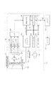
図1は、本発明に関わる画像読取装置に用いられる画像読取装置の一つの例を示すものであり、その画像読取装置の断面図である。
図1において、101はスキャナ本体、102は透過原稿ユニット、103は読み取り原稿である。スキャナ101は、不図示のインターフェースケーブルによりホストコンピュータ(以下、ホストPC)に接続されている。
FIG. 1 shows an example of an image reading apparatus used in an image reading apparatus according to the present invention, and is a sectional view of the image reading apparatus.
In FIG. 1, 101 is a scanner body, 102 is a transparent original unit, and 103 is a read original. The
さらに、スキャナ101は移動光学ユニット104、原稿台ガラス105、電気基板106、パルスモータ107、無端ベルト108、プーリ109、110、ギア列111、ガイドレール112、白色基準板113を有している。白色基準板113の中には、黒マーク136が有り、スキャナ101はこの黒マーク136を基準にして読み取りエリアを決めて画像を読み取っている。光学ユニット104とパルスモータ107はそれぞれ不図示のケーブルにより電気的に接続されている。また、光学ユニット104は、ガイドレール112に載置部114により摺動可能に載置されている。また、載置部114は無端ベルト108に固着されている。
Further, the
そして、移動光学ユニット104は、反射原稿用光源115、複数の反射ミラー116、117、118、結像レンズ119、撮像手段であるラインセンサ120から構成されている。
The moving optical unit 104 includes a reflective
次に、上記構成を有するスキャナ101における反射原稿画像の読み取り動作を簡単に説明する。
スキャナ101における読み取り動作の開始は、ホストPCからの読み取り命令コマンドによる。スキャナ101は、光学ユニット104の反射原稿用光源115を点灯し、原稿からの反射光を複数のミラー116、117、118により反射させ結像レンズ119を介してセンサ120に結像することで主走査方向1ライン分の画像を読み取る。また、パルスモータ107の動力をギア列111によりプーリ109を回転させることで、無端ベルト108を駆動する。これにより、無端ベルト108に対して戴置部114により固着される光学ユニット104は矢印Xで示す副走査方向にガイドレール上を移動する。スキャナ101は、光学ユニット104を副走査方向に移動しつつ、前述の主走査方向のライン画像の読み取りを繰り返す。スキャナ101は、図1の光学ユニット104を点線で示す位置まで読み取り動作をしながら移動させることで、原稿台ガラス105全面のスキャンが可能となる。但し、ホストPCからの読み取りコマンドの内容に応じて、原稿台ガラス105上の原稿の部分画像を読むことが可能である。その場合には、ホストが指定する読み取り画像範囲に対して、主走査方向にはセンサ出力のうち採用する画素範囲を、また副走査方向には光学ユニットの移動範囲を電気基板上の後述の制御部で規定することにより実現する。
Next, the operation of reading the reflected original image in the
The reading operation in the
図2は、主にスキャナ101の機能構成を示すブロック図である。図1に示すものと同じ構成には同じ番号を付す。
まず、光学ユニット104において、224は反射原稿用光源115と透過原稿用光源135を点灯するための光源点灯回路であり、この中に光源の光量検知を行うための検知部が含まれている。反射原稿用光源115と透過原稿用光源135に冷陰極管を用いた場合には、いわゆるインバータ回路となる。
FIG. 2 is a block diagram mainly showing a functional configuration of the
First, in the optical unit 104, reference numeral 224 denotes a light source lighting circuit for lighting the
また、電気基板106において、227R、227G、227Bはアナログゲイン調整器であり、ラインセンサ120から出力されたアナログ画像信号を可変増幅することが可能な構成である。228はA/D変換器であり、可変アナログゲイン調整器227から出力されたアナログ画像信号をデジタル画像信号に変換する。229は画像処理部であり、デジタル信号化された画像信号に対してオフセット補正、シェーディング補正、デジタルゲイン調整、カラーバランス調整、マスキング、主・副走査方向の解像度変換、画像圧縮等の画像処理を行う。
In the
230はラインバッファであり、画像データを一時的に記憶する部分であり、汎用のランダムアクセスメモリで実現している。231はインタフェース部であり、ホストPC221と通信するためのものである。ここではUSBインタフェースで実現しているが、IEEE1394等、別のインタフェースを採用することも可能である。232は画像処理を行う際のワーキングエリアとして用いられるオフセットRAMである。このオフセットRAM232は、ラインセンサ120にRGB用ラインセンサが各々所定のオフセットを持って平行に配置されているので、そのRGBライン間オフセットの補正用として用いられる。また、オフセットRAMは、シェーディング補正等の各種データの一時記憶も行う。ここでは汎用のランダムアクセスメモリで実現している。233はガンマカーブを記憶し、ガンマ補正を行うためのガンマRAMである。
A
226はスキャナ全体のシーケンスを記憶したシステムコントローラであり、ホストPC221からの命令に従って各種制御を行う。234はシステムコントローラ226と画像処理部229とラインバッファ230とインタフェース部231とオフセットRAM232とガンマRAM233をつなぐシステムバスであり、アドレスバスとデータバスによって構成されている。
A
225はパルスモータ107用のモータ駆動回路であり、スキャナ101のシステム制御手段であるシステムコントローラ226からの信号によりパルスモータ107の励磁切り替え信号を出力する。
A motor driving circuit 225 for the
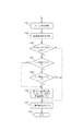
次に図4に示す自動原稿領域推定処理の遷移図と図5のフローチャートを参照しながら、本件の実施形態を説明する。 Next, an embodiment of the present invention will be described with reference to a transition diagram of the automatic document area estimation process shown in FIG. 4 and a flowchart of FIG.
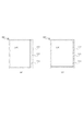
まず、図3のように原稿を設置する。主走査方向が左右方向、副走査方向が上下方向で、原稿の先端が図では上端に示されている。読み取り基準位置マーク301に角を合わせて原稿台302にA4サイズ原稿303を配置した場合を図3(a)、Letterサイズ原稿304を設置した場合を図3(b)に示す。ここで、原稿台302の幅は217mm、高さは298mmとする。また先端レジ、左端レジはそれぞれ5mmである。よって、読み取り可能範囲は幅5〜212mm、高さ5〜293mmである。この領域を図3にそれぞれ破線305で示す。よってこの読み取り装置は、読み取り基準位置マーク301に角を合わせた時、A4サイズ原稿(210mm×297mm)は下辺が、Letterサイズ原稿(215.9mm×279.4mm)は右辺が読み取り可能範囲内にない。図3(a)で設置した原稿303はA4サイズ(210mm×297mm)であり、“ABC”という文字が左上から右50mm、下50mmの箇所にプリントされている。図3(b)で設置した原稿304はLetterサイズ(215.9mm×279.4mm)であり、“ABC”という文字が左上から右50mm、下50mmの箇所にプリントされている。
First, a document is set as shown in FIG. The main scanning direction is the left-right direction, the sub-scanning direction is the up-down direction, and the leading edge of the document is shown at the upper end in the figure. FIG. 3A shows the case where an A4 size original 303 is placed on the original table 302 with the corner aligned with the reading
図3(a)の状態で画像を読み取ると、図4(a)に示す読み取り画像401が得られる。原稿台402の高さは298mmであるが、先端レジの影響で読み取り基準位置マーク301から高さ5〜293mmまでしか読み取れない。そのため、原稿303の高さは297mmであるが、読み取り画像501には原稿403の上辺5mm分と下辺4mm分が存在しない。
When the image is read in the state of FIG. 3A, a
図5のフローチャートのS501は、エッジ抽出処理で、ここでは8方向ラプラシアンフィルタと2値化処理によるエッジ抽出を行う。8方向ラプラシアンフィルタは、ある注目点を中心とした上下左右の9つの画素値に対して、注目点は−8、その他は1の係数を乗算し、その結果を合計する。その合計値が2値化閾値より大きかったらエッジとして抽出する。読み取り画像401に対してS501の処理を行うと、原稿右辺のエッジ402と原稿内プリント”ABC”のエッジ403が得られる。先端レジの5mmの範囲内に原稿の先端が、下辺4mmの範囲内に後端が、左端レジの5mmの範囲内に原稿の左端が夫々存在するので、読取った画像には先端と左端のエッジが存在しない。このために先端、後端と左端のエッジは抽出されない。
S501 in the flowchart of FIG. 5 is edge extraction processing, and here, edge extraction is performed by an 8-direction Laplacian filter and binarization processing. The 8-direction Laplacian filter multiplies nine pixel values, centering on a certain point of interest, up, down, left, and right by a coefficient of -8 for the point of interest and 1 for others, and sums the results. If the total value is larger than the binarization threshold, it is extracted as an edge. When the processing of S501 is performed on the read
S502は、原稿領域推定処理で、S501で得られたエッジをすべて包括する最小矩形を生成する。ここでは、図4(c)の斜線部の最小矩形404は、エッジ402と403を包括する最小矩形である。この最小矩形404は、得られたすべてのエッジの座標の中で、幅方向の最小値と最大値、高さ方向の最小値と最大値を求める。これは、座標点(幅方向最小値、高さ方向最小値)、座標点(幅方向最大値、高さ方向最小値)、座標点(幅方向最大値、高さ方向最大値)、座標点(幅方向最小値、高さ方向最大値)の4点を頂点とする矩形である。この矩形404が推定原稿領域である。
In step S502 , a minimum rectangle that includes all the edges obtained in step S501 is generated in the document area estimation process. Here, the
S503、S504、S505が原稿領域補正処理である。S503は、S502で得られた推定原稿領域404の頂点の中で、読み取り基準位置から一番遠い頂点406がエリア407(図4(e)中の右下の矩形領域)の範囲内にあるかどうかを判定する。エリア407は幅方向202mmから212mmの範囲、高さ方向283mmから293mmとする。最大読み取り位置の幅212mm×高さ293mmから10mmのマージンをとった範囲である。ノイズの影響によりエッジ抽出は完璧ではなく、実際に原稿端があるのに一部が欠けたエッジが得られた場合を想定したマージンである。頂点406はエリア407の範囲にあるのでS504に進む。もし頂点406がエリア407の範囲にない場合、推定原稿領域404の範囲をトリミングして出力する(S507)。
S503 , S504 , and S505 are document area correction processing. In S503 , among the vertices of the estimated
S504はS502で得られた推定原稿領域404の幅(図4(e)中のlx)が202mm(図5中の閾値X)以上かを判定する。幅lxは202mmより小さいため、S505に進む。設置した原稿がLetterサイズの場合(図3(b))、原稿端のエッジは下辺しか得られないため、従来手法だと原稿上部が欠けてトリミングしてしまう。そこで、閾値Xを最大読み取り幅212mmからマージン10mmを設けた202mm以上の場合設置した原稿はLetterサイズであると判定しS506に進む。 In S504, it is determined whether or not the width of the estimated document area 404 (lx in FIG. 4E) obtained in S502 is equal to or greater than 202 mm (threshold X in FIG. 5). Since the width lx is smaller than 202 mm, the process proceeds to S505 . When the placed document is Letter size (FIG. 3B), only the lower edge of the document edge can be obtained. Therefore, if the threshold value X is 202 mm or more with a maximum reading width of 212 mm and a margin of 10 mm, it is determined that the placed document is Letter size, and the process proceeds to S506 .
S505はS502で得られた推定原稿領域404の高さlyが283mm(図5中の閾値Y)以上かを判定する。高さlyは283mm以上のため、設置した原稿はA4サイズであると判定しS506に進む。もし高さlyが283mmより小さい場合、推定原稿領域404の範囲をトリミングして出力する(S507)。
In step S505, it is determined whether the height ly of the estimated
S504とS505の処理は、小さな原稿をA4またはLetterサイズと誤って検出するのを避けるために行われる。小さな原稿の右下端がエリアA内にあるように置かれた場合であっても、その推定原稿領域404の大きさからの判断も行うので、誤検出を防止できる。
The processing in S504 and S505 is performed to avoid erroneously detecting a small document as A4 or Letter size. Even when the small right document is placed so that the lower right corner is within the area A, the determination is made based on the size of the estimated
S506は原稿領域補正処理で、S502で得た推定原稿領域404を、読み取り基準位置側の頂点と頂点406を含む最小矩形405を推定原稿領域と再定義する。そして推定原稿領域405の範囲をトリミングして出力する(S507)。
S506 is a document area correction process, in which the estimated
エリア407の大きさ、辺の閾値X、Yは可変である。例えば、原稿基準位置に合わせて設置してB5サイズ(182mm×257mm)より大きい(192mm×267mm以上)原稿の場合にS506の処理を行うことができる。この場合には、エリア407を幅方向192mmから217mmの範囲、高さ方向267mmから298mmとし、Xを182mm、Yを257mmとする。
The size of the
S501で有効なエッジが得られなかった場合、例外として、原稿台全面(305)を出力する。 If a valid edge is not obtained in S501 , the entire original platen (305) is output as an exception.
上記で用いるエッジ検出の手法として、Laplacianフィルタ、Sobelフィルタ、Robertsフィルタ、Prewittフィルタ、等がある。 As the edge detection method used above, there are a Laplacian filter, a Sobel filter, a Roberts filter, a Prewitt filter, and the like.
(他の実施形態)
複数の機器(たとえば、ホストコンピュータ、インタフェース機器、スキャナ、プリンタ、複合機等)によって構成されているシステムに適応することもできる。
(Other embodiments)
The present invention can also be applied to a system constituted by a plurality of devices (for example, a host computer, an interface device, a scanner, a printer, a multifunction device, etc.).
また、本発明の目的は、前述した実施形態の機能を実現するソフトウェアのプログラムコードを記録した記憶媒体(または記録媒体)を、システムあるいは装置に供給することもできる。そのシステムあるいは装置のコンピュータ(またはCPUやMPU)が記憶媒体に格納されたプログラムコードを読み出し実行することによっても、達成されることは言うまでもない。 The object of the present invention can also supply a system or apparatus with a storage medium (or recording medium) that records a program code of software that implements the functions of the above-described embodiments. Needless to say, this can also be achieved by the computer (or CPU or MPU) of the system or apparatus reading and executing the program code stored in the storage medium.
101 スキャナ本体
102 透過原稿ユニット
103 読み取り原稿
104 移動光学ユニット
105 原稿台ガラス
120 ラインセンサ
135 透過原稿用光源
136 黒マーク
DESCRIPTION OF
Claims (3)
前記原稿が載置された原稿台を読取り、画像データを得る読取工程と、
前記画像データのエッジを抽出する抽出工程と、
前記抽出工程で抽出されたエッジを全て包括する最小矩形の第1矩形を生成する生成工程と、
前記第1矩形の頂点のうち読取の基準位置から最も遠い位置にある頂点が、前記画像データにおける読取の基準位置から最も遠い頂点の位置と、前記エッジ領域を抽出する工程での抽出誤差とを基にして決められる所定の領域内にあるか判定する判定工程と、
前記第1矩形の主走査方向の長さを、前記画像データの主走査方向の大きさと、前記抽出工程での抽出誤差とを基にして決められる所定の閾値Xと比較する第1比較工程と、
前記第1矩形の副走査方向の長さを、前記画像データの副走査方向の大きさと、前記抽出工程での抽出誤差とを基にして決められる所定の閾値Yと比較する第2比較工程と、
前記判定工程で前記所定の領域内であると判定され、かつ、前記第1比較工程で前記第1矩形の主走査方向の長さの方が長いか等しい、又は、前記第2比較工程で前記第1矩形の副走査方向の長さの方が長いか等しいと判定された場合に、前記画像データのうち、前記第1矩形と前記基準位置とを包括する第2矩形の領域の画像データを前記原稿の読取り画像として出力し、上記以外の判定の場合には前記第1矩形の領域の画像データを前記原稿の読取り画像として出力する出力工程とを有することを特徴とする画像処理方法。 An image processing method for reading a document placed on a document table and outputting image data,
A reading step of reading a document table on which the document is placed and obtaining image data;
An extraction step of extracting an edge of the image data;
Generating a first rectangle of a minimum rectangle that includes all the edges extracted in the extraction step;
Among the vertices of the first rectangle, the vertex farthest from the reference position for reading is the position of the vertex farthest from the reference position for reading in the image data, and the extraction error in the step of extracting the edge region. A determination step of determining whether or not the predetermined area is determined based on;
A first comparison step of comparing the length of the first rectangle in the main scanning direction with a predetermined threshold value X determined based on the size of the image data in the main scanning direction and the extraction error in the extraction step; ,
A second comparison step of comparing the length of the first rectangle in the sub-scanning direction with a predetermined threshold Y determined based on the size of the image data in the sub-scanning direction and the extraction error in the extraction step; ,
It is determined in the determination step that it is within the predetermined region, and the length of the first rectangle in the main scanning direction is longer or equal in the first comparison step, or the second comparison step When it is determined that the length of the first rectangle in the sub-scanning direction is longer or equal, image data of a second rectangular area including the first rectangle and the reference position is included in the image data. An image processing method comprising: an output step of outputting as a read image of the original and outputting image data of the first rectangular area as a read image of the original in a case other than the above determination.
Priority Applications (4)
| Application Number | Priority Date | Filing Date | Title |
|---|---|---|---|
| JP2006205945A JP4777178B2 (en) | 2006-07-28 | 2006-07-28 | Image processing method |
| US11/781,708 US8102575B2 (en) | 2006-07-28 | 2007-07-23 | Image processing apparatus and method |
| CN200710136774A CN100586142C (en) | 2006-07-28 | 2007-07-27 | Image processing apparatus and method |
| US13/332,994 US8300277B2 (en) | 2006-07-28 | 2011-12-21 | Image processing apparatus and method for determining document scanning area from an apex position and a reading reference position |
Applications Claiming Priority (1)
| Application Number | Priority Date | Filing Date | Title |
|---|---|---|---|
| JP2006205945A JP4777178B2 (en) | 2006-07-28 | 2006-07-28 | Image processing method |
Publications (3)
| Publication Number | Publication Date |
|---|---|
| JP2008035173A JP2008035173A (en) | 2008-02-14 |
| JP2008035173A5 JP2008035173A5 (en) | 2009-09-10 |
| JP4777178B2 true JP4777178B2 (en) | 2011-09-21 |
Family
ID=38985929
Family Applications (1)
| Application Number | Title | Priority Date | Filing Date |
|---|---|---|---|
| JP2006205945A Active JP4777178B2 (en) | 2006-07-28 | 2006-07-28 | Image processing method |
Country Status (3)
| Country | Link |
|---|---|
| US (2) | US8102575B2 (en) |
| JP (1) | JP4777178B2 (en) |
| CN (1) | CN100586142C (en) |
Families Citing this family (12)
| Publication number | Priority date | Publication date | Assignee | Title |
|---|---|---|---|---|
| CN101262543B (en) * | 2008-04-07 | 2011-05-04 | 苏州佳世达电通有限公司 | Resetting method for scanning device and scanning module |
| JP4653194B2 (en) * | 2008-04-30 | 2011-03-16 | キヤノン株式会社 | Image processing apparatus, image processing apparatus control method, program, and computer-readable storage medium |
| US8650634B2 (en) | 2009-01-14 | 2014-02-11 | International Business Machines Corporation | Enabling access to a subset of data |
| US8610924B2 (en) | 2009-11-24 | 2013-12-17 | International Business Machines Corporation | Scanning and capturing digital images using layer detection |
| US20110122459A1 (en) * | 2009-11-24 | 2011-05-26 | International Business Machines Corporation | Scanning and Capturing digital Images Using Document Characteristics Detection |
| US8441702B2 (en) | 2009-11-24 | 2013-05-14 | International Business Machines Corporation | Scanning and capturing digital images using residue detection |
| US20200019547A1 (en) * | 2011-10-24 | 2020-01-16 | Imagescan, Inc. | Apparatus and method for displaying search results using cognitive pattern recognition in locating documents and information within |
| JP5938631B2 (en) * | 2011-12-19 | 2016-06-22 | パナソニックIpマネジメント株式会社 | Object detection apparatus and object detection method |
| JP5904024B2 (en) * | 2012-06-13 | 2016-04-13 | ブラザー工業株式会社 | Image reading device |
| TW201424380A (en) * | 2012-12-07 | 2014-06-16 | Ind Tech Res Inst | Coding system, coding method, decoding system and decoding method for image and message |
| JP6999511B2 (en) | 2018-07-02 | 2022-01-18 | 東芝テック株式会社 | Document reader and document scanning method |
| JP2023066121A (en) * | 2021-10-28 | 2023-05-15 | 京セラドキュメントソリューションズ株式会社 | Image processing system |
Family Cites Families (10)
| Publication number | Priority date | Publication date | Assignee | Title |
|---|---|---|---|---|
| JPS6416067A (en) * | 1987-07-08 | 1989-01-19 | Minolta Camera Kk | Original detector |
| JP3573512B2 (en) * | 1994-05-17 | 2004-10-06 | オリンパス株式会社 | Image processing method and image processing apparatus |
| US6433896B1 (en) * | 1997-06-10 | 2002-08-13 | Minolta Co., Ltd. | Image processing apparatus |
| CN1200391C (en) * | 2000-03-13 | 2005-05-04 | 鸿友科技股份有限公司 | Image scanner and quick locating method |
| JP2001268367A (en) | 2000-03-22 | 2001-09-28 | Minolta Co Ltd | Image scanning apparatus |
| CN1433215A (en) * | 2002-01-15 | 2003-07-30 | 力捷电脑股份有限公司 | Image pick-up method for scanning system |
| US7558524B2 (en) * | 2002-03-01 | 2009-07-07 | Seiko Epson Corporation | Image reading system |
| CN1477847A (en) * | 2002-08-22 | 2004-02-25 | 力捷电脑股份有限公司 | Method for judging file range and its correspondent scanner structure |
| JP2004096435A (en) | 2002-08-30 | 2004-03-25 | Minolta Co Ltd | Image analyzing device, image analysis method, and image analysis program |
| JP2005115417A (en) * | 2003-10-02 | 2005-04-28 | Canon Inc | Image reading processor, image reading processing method, program, and storage medium |
-
2006
- 2006-07-28 JP JP2006205945A patent/JP4777178B2/en active Active
-
2007
- 2007-07-23 US US11/781,708 patent/US8102575B2/en not_active Expired - Fee Related
- 2007-07-27 CN CN200710136774A patent/CN100586142C/en not_active Expired - Fee Related
-
2011
- 2011-12-21 US US13/332,994 patent/US8300277B2/en not_active Expired - Fee Related
Also Published As
| Publication number | Publication date |
|---|---|
| CN101115115A (en) | 2008-01-30 |
| US8300277B2 (en) | 2012-10-30 |
| US20120086990A1 (en) | 2012-04-12 |
| JP2008035173A (en) | 2008-02-14 |
| US8102575B2 (en) | 2012-01-24 |
| US20080024841A1 (en) | 2008-01-31 |
| CN100586142C (en) | 2010-01-27 |
Similar Documents
| Publication | Publication Date | Title |
|---|---|---|
| JP4777178B2 (en) | Image processing method | |
| US8018629B2 (en) | Image reading apparatus, image reading method, and program for implementing the method | |
| JP2007020122A (en) | Image processing apparatus, control method for image processing apparatus, and program | |
| US8390896B2 (en) | Image reading method, image reading apparatus, and program recording medium | |
| JP2005348103A (en) | Image correcting device, image reader, program, and storage medium | |
| JP2009303164A (en) | Image reading apparatus and method of controlling the same | |
| JP5618664B2 (en) | Image processing method, program, image reading apparatus, and information device | |
| JP5462522B2 (en) | Image processing apparatus, image processing method, and program for causing computer to realize the image processing method | |
| US20100165417A1 (en) | Image processing method, image processing apparatus, and computer-readable storage medium | |
| US8289584B2 (en) | Image processing method, apparatus and program | |
| JP2002262083A (en) | Image processor | |
| JP2005316550A (en) | Image processor, image reader, image inspection device and program | |
| US8422785B2 (en) | Image processing apparatus, image processing method, and program | |
| JP2011015309A (en) | Image reading apparatus, and method of controlling the same | |
| JP4577844B2 (en) | Image processing apparatus, image processing method, program, and storage medium storing program | |
| JP4194210B2 (en) | Image reading apparatus and method for controlling image reading apparatus | |
| JP2958407B2 (en) | Image processing device | |
| JP2010103874A (en) | Image processing apparatus, program and storage medium | |
| JPH1196338A (en) | Image reader | |
| JP2009284299A (en) | Image processors, image forming apparatus, and program | |
| JP2004191421A (en) | Image reader | |
| JPH0822006B2 (en) | Document reader | |
| JP2002165092A (en) | Image processor and image processing method | |
| JP2010010839A (en) | Image reading device, its processing method, and program | |
| JP2000115477A (en) | Image reader, its control method and storage medium |
Legal Events
| Date | Code | Title | Description |
|---|---|---|---|
| A521 | Request for written amendment filed |
Free format text: JAPANESE INTERMEDIATE CODE: A523 Effective date: 20090728 |
|
| A621 | Written request for application examination |
Free format text: JAPANESE INTERMEDIATE CODE: A621 Effective date: 20090728 |
|
| RD04 | Notification of resignation of power of attorney |
Free format text: JAPANESE INTERMEDIATE CODE: A7424 Effective date: 20100201 |
|
| RD01 | Notification of change of attorney |
Free format text: JAPANESE INTERMEDIATE CODE: A7421 Effective date: 20100630 |
|
| A977 | Report on retrieval |
Free format text: JAPANESE INTERMEDIATE CODE: A971007 Effective date: 20110311 |
|
| A131 | Notification of reasons for refusal |
Free format text: JAPANESE INTERMEDIATE CODE: A131 Effective date: 20110329 |
|
| A521 | Request for written amendment filed |
Free format text: JAPANESE INTERMEDIATE CODE: A523 Effective date: 20110530 |
|
| TRDD | Decision of grant or rejection written | ||
| A01 | Written decision to grant a patent or to grant a registration (utility model) |
Free format text: JAPANESE INTERMEDIATE CODE: A01 Effective date: 20110628 |
|
| A01 | Written decision to grant a patent or to grant a registration (utility model) |
Free format text: JAPANESE INTERMEDIATE CODE: A01 |
|
| A61 | First payment of annual fees (during grant procedure) |
Free format text: JAPANESE INTERMEDIATE CODE: A61 Effective date: 20110629 |
|
| R150 | Certificate of patent or registration of utility model |
Free format text: JAPANESE INTERMEDIATE CODE: R150 Ref document number: 4777178 Country of ref document: JP Free format text: JAPANESE INTERMEDIATE CODE: R150 |
|
| FPAY | Renewal fee payment (event date is renewal date of database) |
Free format text: PAYMENT UNTIL: 20140708 Year of fee payment: 3 |