JP4767471B2 - Selective address table aging in network switches - Google Patents
Selective address table aging in network switches Download PDFInfo
- Publication number
- JP4767471B2 JP4767471B2 JP2001565591A JP2001565591A JP4767471B2 JP 4767471 B2 JP4767471 B2 JP 4767471B2 JP 2001565591 A JP2001565591 A JP 2001565591A JP 2001565591 A JP2001565591 A JP 2001565591A JP 4767471 B2 JP4767471 B2 JP 4767471B2
- Authority
- JP
- Japan
- Prior art keywords
- network
- application
- data packet
- network switch
- received
- Prior art date
- Legal status (The legal status is an assumption and is not a legal conclusion. Google has not performed a legal analysis and makes no representation as to the accuracy of the status listed.)
- Expired - Lifetime
Links
Images


Classifications
-
- H—ELECTRICITY
- H04—ELECTRIC COMMUNICATION TECHNIQUE
- H04L—TRANSMISSION OF DIGITAL INFORMATION, e.g. TELEGRAPHIC COMMUNICATION
- H04L12/00—Data switching networks
- H04L12/28—Data switching networks characterised by path configuration, e.g. LAN [Local Area Networks] or WAN [Wide Area Networks]
-
- H—ELECTRICITY
- H04—ELECTRIC COMMUNICATION TECHNIQUE
- H04L—TRANSMISSION OF DIGITAL INFORMATION, e.g. TELEGRAPHIC COMMUNICATION
- H04L12/00—Data switching networks
- H04L12/28—Data switching networks characterised by path configuration, e.g. LAN [Local Area Networks] or WAN [Wide Area Networks]
- H04L12/46—Interconnection of networks
- H04L12/4604—LAN interconnection over a backbone network, e.g. Internet, Frame Relay
- H04L12/462—LAN interconnection over a bridge based backbone
- H04L12/4625—Single bridge functionality, e.g. connection of two networks over a single bridge
-
- H—ELECTRICITY
- H04—ELECTRIC COMMUNICATION TECHNIQUE
- H04L—TRANSMISSION OF DIGITAL INFORMATION, e.g. TELEGRAPHIC COMMUNICATION
- H04L69/00—Network arrangements, protocols or services independent of the application payload and not provided for in the other groups of this subclass
- H04L69/28—Timers or timing mechanisms used in protocols
Abstract
Description
【0001】
【発明の背景】
発明の分野
この発明は、サブネットワーク間でデータパケットを交換するよう構成されたノンブロッキングネットワークスイッチにおけるデータパケットの交換に関する。
【0002】
背景技術
米国特許第5,914,956号は、非同期転送モード(ATM)スイッチの接続能力を向上させるための、キャッシュ装置および方法を開示する。スイッチを通るデータセルのフローがモニタされ、未使用のまたは十分に用いられていないコネクションが検出されて、再生エイジャー(reclaim ager)によってコネクションテーブルにマークされるが、これは定期的にコネクションのアクティビティを評価する。
IEEEコンピュータ協会のLAN MAN標準委員会(LAN MAN Standards Committee of the IEEE Computer Society)の、「システム間の情報技術電気通信および情報交換−ローカルおよびメトロポリタンエリアネットワーク−一般仕様−第3部:メディアアクセス制御(MAC)ブリッジ(Information technology - Telecommunications and information exchange between systems - Local and metropolitan area networks - Common specifications - Part 3: Media Access Control (MAC) Bridges)」、ISO/IEC15802−3:1998 ANSI/IEEE標準802.1D、1998年版、42−26頁は、IEEE803.2プロトコルにしたがったMACブリッジを開示する。この規格に従った古くなったアドレスの扱いを、以下に説明する。
ローカルエリアネットワークは、ネットワークケーブルまたは他の媒体を用いてネットワーク上のステーションをリンクする。各ローカルエリアネットワークアーキテクチャは、メディアアクセス制御(MAC)を用いて各ネットワークノードでネットワークインターフェイス装置をイネーブルし、ネットワーク媒体にアクセスする。
【0003】
イーサネット(R)プロトコルIEEE802.3は、データパケット送信のための半二重メディアアクセス機構および全二重メディアアクセス機構を指定するために開発された。全二重メディアアクセス機構は、2つのネットワーク要素間の、たとえばネットワークノードと交換ハブ(switched hub)間の、2方向のポイント・ツー・ポイント通信リンクを提供する。
【0004】
交換ローカルエリアネットワークに対して、さらなる高速接続性、より柔軟な交換性能、およびより複雑なネットワークアーキテクチャへの対処能力への要求が高まっている。たとえば、本発明の譲受人に譲渡された米国特許第5,953,335号は、レイヤ2タイプのイーサネット(R)(IEEE802.3)データパケットを異なったネットワークノード間で交換するよう構成されたネットワークスイッチを開示する;受信されたデータパケットは、別のサブネットワーク(ルータを介する)または予め規定されたステーションのグループを指定するIEEE802.1qプロトコルにしたがったVLAN(バーチャルLAN)タグ付きフレームを含み得る。スイッチングはレイヤ2レベルで行なわれるので、典型的にはルータがサブネットワーク間でデータパケットを転送するために必要である。
【0005】
既存のレイヤ2タイプネットワークスイッチの1つの問題は、ユーザによって設定される固定されたエイジング間隔を有するエイジング機能を用いて、古くなった(aged)アドレスエントリをネットワークスイッチアドレステーブルから削除することに関わる。特に、ネットワークスイッチは、受信したデータパケットが、たとえば未知のMACソースまたはデスティネーションアドレスのような未知のアドレスを有することを検出すると、新しいアドレスエントリをネットワークスイッチアドレステーブルに加えることにより、新しいネットワークアドレスを「学習」する。ネットワークスイッチはまた、古くなったアドレスエントリを削除してネットワークスイッチアドレステーブルがオーバーフローすることを防ぐためのエイジング機能をも含む。たとえば、ネットワークスイッチのスイッチファブリックは、受信したデータパケットを交換するためにアドレスエントリがアクセスされるごとに、アドレスエントリ内に「ヒットビット」を設定し得る。エイジング機能は、設定された「ヒットビット」の検出に応答して、ビットをゼロにリセットし、アドレスエントリをネットワークスイッチアドレステーブル内に維持する。もしエイジング機能が、アドレスエントリが少なくとも固定アドレス間隔の間アクセスされていないことを示して「ヒットビット」がすでにゼロ値にリセットされていることを検出すると、エイジング機能は古くなったアドレスエントリをネットワークスイッチアドレステーブルから削除する。
【0006】
しかしながら上述のエイジング機能を用いると、ネットワークスイッチからのアドレスエントリの早過ぎる削除をまねくおそれがあり、ネットワークスイッチはネットワークアドレスを再学習することが必要になる。たとえば、2つのネットワークアプリケーションの間でより高いプロトコルの通信(すなわち、フロー)が生じていることを認識していないレイヤ2スイッチは、ユーザ定義エイジング間隔が短すぎる値に設定されていれば、2つのネットワークアプリケーションの間でのフローに関連するデータパケットに対するアドレスエントリを削除および再学習を繰り返し、ネットワークスイッチリソースを無駄にするおそれがある。しかしながら、ユーザ定義エイジング間隔を増大する試みは、ネットワークスイッチアドレステーブルをオーバーフローさせかねない。
【0007】
【発明の要約】
ネットワークスイッチが、そのネットワークスイッチアドレステーブルからアドレスエントリを選択的に削除する一方で、削除されたアドレスエントリの再学習を最小化することを可能にする構成に対する必要性がある。
【0008】
また、ネットワークスイッチが、2つのネットワークアプリケーションの間のネットワークスイッチによって転送されるデータフローの状態に基づいて、そのネットワークスイッチアドレステーブルからアドレスエントリを選択的に削除することを可能にする構成に対する必要性がある。
【0009】
これらおよび他の必要性はこの発明によって満たされるが、この発明においてはネットワークスイッチは、受信したデータパケットからのデータフローの判断されたアプリケーション状態に基づいて、ネットワークスイッチアドレステーブルからアドレスエントリを選択的に削除する。
【0010】
この発明の一局面は、統合ネットワークスイッチにおける方法を提供し、方法は、受信したレイヤ2データパケットから予め規定されたネットワークアプリケーションに対するアプリケーション状態を判断するステップと、判断したアプリケーション状態に基づいて、受信したレイヤ2データパケットのソースおよびレイヤ2データパケットのデスティネーションの少なくとも1つを指定するネットワークスイッチアドレステーブルからアドレスエントリを選択的に削除するステップとを含む。統合ネットワークスイッチによるアプリケーション状態の判断により、統合ネットワークスイッチが、予め規定されたネットワークアプリケーションにしたがってネットワークノード間のデータフローの存在を識別することが可能になり、統合ネットワークスイッチが予め規定されたネットワークアプリケーションパラメータにしたがってエイジングタイマを調節することが可能になる。さらに、判断されたアプリケーション状態に基づくアドレスエントリの選択的削除により、統合ネットワークスイッチが、アプリケーション状態からネットワークノード間のデータフローがたとえば2つのノード間のセッションの最後で終了したと判断した際に、アドレスエントリを削除することが可能になる。
【0011】
この発明の別の局面は、ネットワークスイッチポートとスイッチング論理とを含むネットワークスイッチを提供する。ネットワークスイッチポートは各々、受信したレイヤ2データパケットから複数の予め規定されたネットワークアプリケーションのうちの検出された1つに対するアプリケーション状態を判断するよう構成されるパケットクラシファイアを含む。スイッチング論理は、判断されたアプリケーション状態および、アプリケーション特有エイジング間隔の間に判断されたアドレスエントリのインアクティビティに基づいて、受信レイヤ2データパケットのソースおよび受信レイヤ2データパケットのデスティネーションの少なくとも1つを指定するアドレスエントリを選択的に削除するよう構成され、ここでアプリケーション特有エイジング間隔は、検出された1つの予め規定されたネットワークアプリケーションに基づく。よって、スイッチング論理は、受信レイヤ2データパケットから検出された1つの予め規定されたネットワークアプリケーションに基づくインアクティビティの間隔に基づいて、アドレスエントリを選択的に削除し、統合ネットワークスイッチによってサポートされるネットワークアプリケーションに基づくより正確なエイジング間隔の使用を可能にする。これに代えて、スイッチング論理は、判断したアプリケーション状態に基づいてアドレスエントリを選択的に削除して、検出された1つの予め規定されたネットワークアプリケーションにしたがった2つのネットワークノードの間のセッションの完了の際に、スイッチング論理がアドレスエントリを削除することを可能にする。
【0012】
この発明のさらなる利点と新規な特徴とは、一部は以下の説明により明らかとなり、一部は当業者においては以下を検討すれば明らかであるか、またはこの発明を実施することにより学習されるであろう。この発明の利点は、前掲の特許請求の範囲に特に指摘される手段および組み合わせにより、実現され達成されるであろう。
【0013】
添付の図面を参照すると、同様の参照番号を有する要素は図面を通して同様の要素を示す。
【0014】
【発明を実行するためのベストモード】
開示される実施例は、ネットワークスイッチアドレステーブルエントリに対するアプリケーションに基づくエイジング間隔を生成するための統合ネットワークスイッチにおける構成、および受信レイヤ2データパケットから予め規定されたネットワークアプリケーションに対して判断されたアプリケーション状態に基づいてアドレスエントリを選択的に削除することに向けられる。受信レイヤ2データパケットから予め定められたネットワークアプリケーションを検出すること、および予め定められたネットワークアプリケーションに対するアプリケーション状態を検出することは、レイヤ2データパケットを受信したネットワークスイッチポート内のパケットクラシファイアモジュールによって行なわれる。第1にエトスアーキテクチャおよびパケットクラシファイアについての説明を提供し、次いでネットワークスイッチアドレスエントリのアプリケーションに基づくエイジングの説明を行なう。
【0015】
図1は、イーサネット(R)(IEEE802.3)ネットワークのようなパケット交換ネットワーク10を示すブロック図である。パケット交換ネットワークはネットワークステーション14間でのデータパケット通信を可能にする統合(すなわち単一チップ)マルチポートスイッチを含む。各ネットワークステーション14、たとえば顧客ワークステーションは典型的には、IEEE802.3プロトコルにしたがってデータパケットを10Mbpsまたは100Mbpsで送受信するよう構成される。各統合マルチポートスイッチ12は、ギガビットイーサネット(R)リンク16で相互接続されており、サブネットワーク18a、18b、18cの間のデータパケット転送を可能にする。よって、各サブネットワークはスイッチ12と、関連のネットワークステーション14のグループとを含む。
【0016】
各スイッチ12は、メディアアクセス制御(MAC)モジュール22とパケットクラシファイアモジュール24とを含むスイッチポート20を含む。MACモジュール20は、IEEE802.3uプロトコルにしたがって、10/100Mbps物理層(PHY)トランシーバ(図示せず)をわたって関連のネットワークステーション14とデータパケットを送受信する。各スイッチ12はまた、受信データパケットに対するフレーム転送判断を行なうよう構成されたスイッチファブリック25をも含む。特に、スイッチファブリック25は、イーサネット(R)(IEEE802.3)ヘッダ内のソースアドレス、デスティネーションアドレス、およびVLAN情報に基づいたレイヤ2スイッチング判断に対して構成されている;スイッチファブリック25はまた、イーサネット(R)パケット内のIPデータパケットの評価に基づいた選択的なレイヤ3スイッチング判断に対しても構成されている。
【0017】
図1に示されるように、各スイッチ12は、関連のホストCPU26とたとえばSSRAMであるバッファメモリ28とを有する。ホストCPU26は、以下に説明するスイッチファブリック25およびパケットクラシファイアのプログラミングを含む、対応のスイッチ12の全体的な動作を制御する。バッファメモリ28は対応のスイッチ12によって用いられて、スイッチファブリック25が受信したデータパケットに対する転送判断を処理している一方で、データフレームをストアする。
【0018】
上述のように、スイッチファブリック25はレイヤ2スイッチング判断とレイヤ3スイッチング判断とを行なうよう構成されている。スイッチファブリック25によるレイヤ3スイッチング判断を用いると、スイッチファブリック25が先取り(advanced)転送判断を含めてどのようにパケットを扱うか、およびパケットをビデオまたは音声などのレイテンシ感応アプリケーションに対する高優先性パケットとみなすべきか、についてまで知的な判断が行なえるようになる。
【0019】
開示される実施例にしたがうと、図1のパケットクラシファイアモジュール24は、入ってくるデータストリームと、入ってくるデータストリームのデータ形式を識別するテンプレートとの間の多数同時比較に対して構成される。特定的には、ホストプロセッサ26のユーザは、受信データパケットの選択部分におけるある予め規定されたデータ値を有するデータパケットがどのようにスイッチファブリック25によって扱われるべきかを定義するポリシーを指定する。これらのポリシーは対応のポリシーごとに、スイッチファブリック25に1組のフレーム転送判断またはエイジング機能パラメータをローディングすることにより実現される。受信データパケットの選択部分におけるある予め規定されたデータ値は、レイヤ2データパケットのどの部分に場所決めされていてもよいことに留意されたい。よって、パケットクラシファイアモジュール24は、たとえばハイパーテキスト転送プロトコル、SNMP,FTP,Telnetのような異なったネットワークアプリケーションにしたがったデータフローの存在を検出できる。
【0020】
よって、スイッチファブリック25はHTTPパケットについて1組のフレーム転送命令およびエイジングパラメータと、SNMPパケットに対する別の組のフレーム転送命令およびおよびエイジングパラメータと、高優先性パケット(たとえばビデオ、音声)に対する別の組のフレーム転送命令およびおよびエイジングパラメータとを含み得る。
【0021】
図2は、この発明の実施例にしたがったパケットクラシファイアモジュール24を示すブロック図である。図2に示すように、ネットワークスイッチポート20は、MAC22と、受信FIFOバッファ27と、ヘッダモディファイア29と、パケットクラシファイアモジュール24とを含む。ネットワークスイッチポートフィルタとも称するパケットクラシファイアモジュール24は、ネットワークスイッチポート20で入ってくるデータパケットを識別し(すなわち、評価し)、かつスイッチファブリック25に受信されたデータパケットのタイプに基づくデータパケットに対して行なわれるべきアクションを指定するタグを与える。特定的には、パケットクラシファイアモジュール24は、入ってくるデータパケットを、それぞれの受信データ形式を識別するよう構成された複数のテンプレートと同時に比較する。入ってくるデータパケットと複数のテンプレートとの比較に基づいて、パケットクラシファイアモジュール24は、スイッチファブリック25に与えられるべきタグを指定する、実行されるべき方程式を識別する。
【0022】
特定的には、パケットクラシファイアモジュール24は複数のテンプレートから少なくとも1つの整合するテンプレートを検出することにより入ってくるデータパケットを識別する比較結果を生成する。パケットクラシファイアモジュール24は次いで、どの方程式が整合したテンプレートを含むかを識別し、その方程式によって指定されるタグを生成する。
【0023】
図3Aおよび図3Bは、パケットクラシファイアモジュール24による方程式の2つのテンプレートの同時処理を示す図である。図3Aは、方程式Eq1=M1*M2*M3*M4*(M5+M6+M7+M8)のパケットクラシファイアモジュール24による論理評価を示す。
【0024】
図3Bは、どのように方程式Eq1が実際に極小項(min term)メモリ70にストアされるかを示す。方程式Eq1は4つのテンプレート62a、62b、62c、および62dを含む。テンプレート62aは、極小項M1、M2、M3、M4およびM5を含む。テンプレート62bは、極小項M1、M2、M3、M4およびM6を含む。テンプレート62cは、極小項M1、M2、M3、M4およびM7を含む。テンプレート62dは、極小項M1、M2、M3、M4およびM8を含む。各テンプレート62は、IPデータパケット32のヘッダに基づいて認識可能である特定のIPデータ形式に対応する。たとえば、テンプレート62aおよび62cは、HTTPパケットを識別するよう構成され、テンプレート62bおよび62dは、SNMPパケットを識別するよう構成され得る。特定的には、HTTPパケットは、IPv4形式であるか、IPのtime to live フィールドは1よりも大きいか、IPヘッダのプロトコルフィールドはTCPであるか、ヘッダチェックサムは正しいか、ソースTCPポートは80であるか、またはデスティネーションTCPポートは80であるか、が識別される。SNMPパケットは、IPv4形式であるか、IPのtime to live フィールドは1よりも大きいか、IPヘッダのプロトコルフィールドはTCPであるか、ヘッダチェックサムは正しいか、ソースTCPポートは25であるか、またはデスティネーションTCPポートは25であるか、が識別される。
【0025】
よって、以下の極小項が上述の基準のすべてを表すために確立され得る:
M1=パケットはIPv4形式である
M2=IPのtime to live フィールドは1よりも大きい
M3=IPヘッダのプロトコルフィールドはTCPである
M4=ヘッダチェックサムは正しい
M5=ソースTCPポートは80である
M6=デスティネーションTCPポートは80である
M7=ソースTCPポートは25である
M8=デスティネーションTCPポートは25である
よって、テンプレート62aと62cとはHTTPパケットを識別し、テンプレート62bと62dとはSNMPパケットを識別する。こうして、方程式1(Eq1)は、テンプレート62a、62b、63c、62dのいずれかが真であれば、特定の結果(たとえば指定された値を有するタグ)がスイッチファブリック25に出力されるべきことを指定する。
【0026】
さらに、極小項M1…M8は、入来データストリーム内のデータバイトの相対的な位置に対応する予め規定された順序で関連のテンプレート62aおよび/または62b内に配置される。極小項M1は、IPパケットの第1のバイト(B1)との比較のために構成され、極小項M2はB1の後に続くIPパケットの後のバイト(B2)との比較のために構成され、極小項M3はB2の後に続くIPパケットの後のバイト(B3)との比較のために構成され、以下同様である。よって、入来データストリーム内のデータバイトの相対的な位置に基づく順序での極小項を有するテンプレート62を用いると、入来データストリームと極小項との間の多数同時比較が可能になる。よって、入来データパケットは多数のテンプレートと比較されて、入来データパケットの形式だけでなく、スイッチファブリック25によってどのアクションが行なわれなければならないかをも判断する。
【0027】
図2に示されるように、ネットワークスイッチポートフィルタとも称するパケットクラシファイア24は、極小項値(たとえばM1、M2など)をストアするための極小項メモリ70と、受信されるレイヤ2フレームのタイプを識別するよう構成されるフレームアイデンティファイア72とを含む。特に、受信されているレイヤ2フレームのタイプを識別することは(たとえばイーサネット(R)IEEE802から3など)、レイヤ2パケット30内のIPパケット32の開始位置64の識別を可能にする。パケットクラシファイア24はまた、極小項コントローラ74、極小項ジェネレータ76、方程式コア78、および評価結果メモリ80を含む。プロセッサインターフェイスモジュール(pi mod)82は、ホストCPU26から極小項メモリ70に、生成された極小項を転送するために用いられる。
【0028】
極小項コントローラ74は、受信IPフレームの選択されたバイトに対応する極小項メモリ70から極小項をフェッチするよう構成される。極小項コントローラ74はまた、レイヤ2フレームのタイプを指定するフレームアイデンティファイア72からのフレームタイプ(frm type)信号の受信に応答して開始ポイントの実際のバイト位置(byte location)を指定するよう構成される位置コンバータをも含む。極小項コントローラ74は次いで、極小項値(M STRU INFO)を極小項ジェネレータ76と方程式コア78とに転送する。
【0029】
極小項ジェネレータ76は、極小項コントローラによってフェッチされた極小項と入来データストリームの選択されたバイトとの間の、実際極小項比較を行ない、実際極小項比較の結果(mt result)を方程式コア78に送る。開示される実施例に従うと、極小項ジェネレータは入来データストリームの最大8極小項までの同時比較に対して構成される。方程式コア78は、関連のテンプレート62に対する、極小項ジェネレータ76から受信した極小項比較結果に基づいて、フレームタグを生成するよう構成される。
【0030】
上述のように、パケットクラシファイアモジュール24は、受信レイヤ2データパケットがたとえばHTTP、SNMP、FTP、Telnetのような予め規定されたネットワークアプリケーションに対するフレームデータを担持するかどうかを、各ネットワークスイッチポート20が識別することを可能にする。さらに、パケットクラシファイアモジュール24は、受信レイヤ2データパケットから、アプリケーション状態を特定的に識別するよう、付加的なテンプレートでプログラム可能である。特定的には、ネットワークノードは予め規定されたネットワークアプリケーションにしたがって通信し、2つのネットワークノード間の予め規定されたデータフローをもたらす。よって、ネットワークノード間で転送されるレイヤ2データパケットは、たとえばセッション開始要求、肯定応答、セッションの間の通信、セッション終了要求、およびセッション終了の肯定応答のような、予め規定されたネットワークアプリケーション状態を指定するペイロード情報を含み得る。パケットクラシファイアモジュール24は、レイヤ2データパケットのペイロードデータを評価することにより、データフローの状態をモニタするための適切なテンプレートでプログラムされ得る。よって、パケットクラシファイアモジュール24は、2つのネットワークノード間で動作するネットワークアプリケーションに対するアプリケーション状態をモニタでき、スイッチファブリック25のスイッチング論理がアプリケーションに基づくエイジング動作を行なうことを可能にする。
【0031】
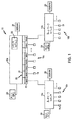
図4は、この発明の実施例にしたがった図1のスイッチファブリック25を詳細に示す図である。図4に示されるように、スイッチファブリック25はスイッチング論理80と、ネットワークスイッチアドレステーブル82とを含む。ネットワークスイッチアドレステーブル82は、外部アドレステーブルとしてネットワークスイッチ12の外部に実現されてもよいことに留意されたい。スイッチング論理80は、ネットワークスイッチアドレステーブル82内のアドレステーブルエントリ84の学習(すなわちストア)を制御する。
【0032】
各アドレステーブルエントリ84は、MACアドレスフィールド84c、IPアドレスフィールド84d、および、対応のMACおよび/またはIPアドレスを有するネットワークノードに対する対応のレイヤ2および/またはレイヤ3スイッチング情報を提供するスイッチング情報フィールド84eを含む。各アドレステーブルエントリ84はまた、エイジングタイマのための開始時間をストアするよう構成されるエイジングタイマ開始フィールド84aと、判断されたデータフローによってサポートされるネットワークアプリケーションに基づいて、アプリケーション特有エイジング時間間隔をストアするよう構成されるエイジング間隔フィールド84bとを有する。
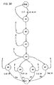
【0033】
図5は、この発明の実施例にしたがった、ネットワークスイッチアドレステーブル82のアプリケーションに基づくエイジングを行なう方法を示すフロー図である。フロー図として示されるが、実際の実現化は状態に基づくものであって、スイッチング論理80内の新しい状態がパケットクラシファイアモジュール24からの予め規定されたアクションタグに応答して実行される。
【0034】
方法はステップ90において開始し、ここでホストCPUは、受信レイヤ2データパケットに基づく各ネットワークアプリケーションを識別するよう構成される、アプリケーションテンプレートの少なくとも最初の組を、パケットクラシファイアモジュール24の極小項メモリ70にローディングする。特に、ネットワークノードは予め規定されたネットワークアプリケーションにしたがってセッション開始要求を最初に送信する。ネットワークノードからの最初の要求の検出に応答して、パケットクラシファイアモジュール24は、新しいネットワークノードおよび対応の識別されたネットワークアプリケーションを指定するタグをスイッチファブリック25に送る。スイッチング論理80は、次いでステップ92においてネットワークスイッチアドレステーブル82に別のエントリ84を加えることにより、エントリを学習する。ホストCPUもまた新しいデータフローを通知され、ステップ94においてホストCPUはその時点で検出されたアプリケーションに対する付加的なテンプレートを極小項メモリ70にストアし、パケットクラシファイアモジュール24が検出されたデータフローに対する各アプリケーション状態を識別することを可能にする。これに代えて、一度にすべてのテンプレートが極小項メモリ70にローディングされてもよい。
【0035】
ネットワークアプリケーションが対応の受信レイヤ2データパケットによってサポートされていることを検出すると、ホストCPU26は応答してアプリケーション特有エイジング間隔(たとえばT1)をエイジング間隔フィールド84bにローディングし、タイマに対する開始時間をエイジングタイマ開始フィールド84aにステップ96において記録する。
【0036】
レイヤ2データパケットを受信したネットワークスイッチポート20のパケットクラシファイアモジュール24は、ネットワークアプリケーションの識別されたデータフローに対するペイロードデータを有するさらなるレイヤ2データパケットについてモニタを続ける。ステップ98においてパケットクラシファイアモジュール24が既存のデータフローに対して新しい状態を検出し、かつステップ100において新しい状態が識別されたネットワークアプリケーションにしたがったデータフローに対するセッションの終了を示すと、パケットクラシファイアモジュール24はセッションの終了を指定するアクションタグをスイッチング論理80に出力し、スイッチング論理80にステップ102において対応のアドレステーブルエントリ84を削除させる。しかしながら、ステップ100において新しい状態がパケットクラシファイア24によって中間アプリケーション状態であると判断されると、パケットクラシファイア24はスイッチング論理80に適切なタグを送り、フィールド84aにおける開始時間を更新された値でオーバーライドすることにより、ステップ104でスイッチング論理80にタイマをリセットさせる。
【0037】
スイッチング論理80は、アプリケーション特有エイジング間隔を、その内部クロックを開始時間エントリ84bに対して開始時間エントリ84aと比較することにより、連続的にモニタする。スイッチング論理80が、エイジング間隔フィールド84bに指定されるアプリケーション特有エイジング間隔の間、対応のアドレステーブルエントリがアクセスされていないことを示して、アプリケーション特有タイマがステップ106において期限が切れていると判断するれば、スイッチング論理80はステップ102においてエントリ80を削除する。
【0038】
開示される実施例にしたがうと、アプリケーション特有エイジング間隔が、判断されたアプリケーション状態と組合せて用いられて、アドレスエントリがいつネットワークスイッチアドレステーブルから削除されるべきかを正確に判断する。よって、アドレステーブルは、ネットワークスイッチによって生じるデータフローに基づくネットワークスイッチによって正確に維持され得る。
【0039】
この発明を最も実際的な実施例であるとここで考えられるものによって説明してきたが、この発明は開示される実施例に限定されるものではなく、その反対に、さまざまな変形と等価な構成とを、前掲の特許請求の範囲に含むことが意図されることを理解されたい。
【図面の簡単な説明】
【図1】 この発明の実施例にしたがったそれぞれのサブネットワークの間のデータパケットを交換するための、多数のネットワークスイッチを含む、パケット交換ネットワークのブロック図である。
【図2】 この発明の実施例にしたがったパケットクラシファイアモジュールを含む、図1のネットワークスイッチポートを示すブロック図である。
【図3A】 図2の極小項ジェネレータによる方程式の4つのテンプレートの同時処理を示す図である。
【図3B】 図2の極小項ジェネレータによる方程式の4つのテンプレートの同時処理を示す図である。
【図4】 図1のスイッチング論理を詳細に示す図である。
【図5】 この発明の実施例にしたがった、判断されたアプリケーション状態およびアプリケーション特有エイジング間隔に基づいてアドレスエントリを選択的に削除する方法を示す図である。[0001]
BACKGROUND OF THE INVENTION
Field of Invention
The present invention relates to exchanging data packets in a non-blocking network switch configured to exchange data packets between sub-networks.
[0002]
Background art
U.S. Pat. No. 5,914,956 discloses a cache device and method for improving the connection capability of asynchronous transfer mode (ATM) switches. The flow of data cells through the switch is monitored, unused or underutilized connections are detected and marked in the connection table by a reclaim ager, which is periodically connected activity To evaluate.
"Information Technology Telecommunications and Information Exchange Between Systems-Local and Metropolitan Area Networks-General Specification-Part 3: Media Access Control" of the LAN MAN Standards Committee of the IEEE Computer Society of the IEEE Computer Association (MAC) bridges (Information technology-Telecommunications and information exchange between systems-Local and metropolitan area networks-Common specifications-Part 3: Media Access Control (MAC) Bridges) ", ISO / IEC 15802-3: 1998 ANSI / IEEE standard 802. 1D, 1998, pages 42-26, discloses a MAC bridge according to the IEEE 803.2 protocol. The handling of obsolete addresses according to this standard is described below.
A local area network links stations on the network using network cables or other media. Each local area network architecture uses media access control (MAC) to enable a network interface device at each network node to access the network medium.
[0003]
The Ethernet protocol IEEE 802.3 was developed to specify a half-duplex media access mechanism and a full-duplex media access mechanism for data packet transmission. A full-duplex media access mechanism provides a two-way point-to-point communication link between two network elements, eg, between a network node and a switched hub.
[0004]
For switched local area networks, there is an increasing demand for higher speed connectivity, more flexible switching performance, and the ability to cope with more complex network architectures. For example, US Pat. No. 5,953,335, assigned to the assignee of the present invention, was configured to exchange
[0005]
One problem with existing
[0006]
However, using the aging function described above may lead to premature deletion of address entries from the network switch, requiring the network switch to relearn the network address. For example, a
[0007]
SUMMARY OF THE INVENTION
There is a need for a configuration that allows a network switch to selectively delete address entries from its network switch address table while minimizing relearning of deleted address entries.
[0008]
There is also a need for a configuration that allows a network switch to selectively delete address entries from its network switch address table based on the state of data flows transferred by the network switch between two network applications. There is.
[0009]
These and other needs are met by the present invention, in which the network switch selectively selects address entries from the network switch address table based on the determined application state of the data flow from the received data packet. To delete.
[0010]
One aspect of the invention provides a method in an integrated network switch, the method comprising: determining an application state for a predefined network application from a received
[0011]
Another aspect of the invention provides a network switch that includes a network switch port and switching logic. Each network switch port includes a packet classifier configured to determine an application state for a detected one of a plurality of predefined network applications from received
[0012]
Further advantages and novel features of the present invention will be in part apparent from the description which follows, and in part will be apparent to those skilled in the art upon consideration of the following or may be learned by practice of the invention. Will. The advantages of the invention will be realized and attained by means of the instrumentalities and combinations particularly pointed out in the appended claims.
[0013]
Referring to the accompanying drawings, like reference numerals indicate like elements throughout the drawings.
[0014]
Best mode for carrying out the invention
The disclosed embodiment includes a configuration in an integrated network switch to generate an application-based aging interval for a network switch address table entry, and an application state determined for a predefined network application from received
[0015]
FIG. 1 is a block diagram illustrating a packet switched
[0016]
Each switch 12 includes a
[0017]
As shown in FIG. 1, each switch 12 has an associated
[0018]
As described above, the
[0019]
In accordance with the disclosed embodiment, the
[0020]
Thus, the
[0021]
FIG. 2 is a block diagram illustrating a
[0022]
Specifically, the
[0023]
3A and 3B are diagrams illustrating the simultaneous processing of two templates of equations by the
[0024]
FIG. 3B shows how equation Eq1 is actually stored in
[0025]
Thus, the following minimal terms can be established to represent all of the above criteria:
M1 = packet is in IPv4 format
M2 = IP time to live field is greater than 1
M3 = IP header protocol field is TCP
M4 = Header checksum is correct
M5 = Source TCP port is 80
M6 = Destination TCP port is 80
M7 = Source TCP port is 25
M8 = Destination TCP port is 25
Thus,
[0026]
Furthermore, the minimal terms M1... M8 are placed in the associated
[0027]
As shown in FIG. 2, the
[0028]
The minimal term controller 74 is configured to fetch the minimal term from the
[0029]
The
[0030]
As described above, the
[0031]
FIG. 4 shows in detail the
[0032]
Each
[0033]
FIG. 5 is a flow diagram illustrating a method for aging based on the application of the network switch address table 82 in accordance with an embodiment of the present invention. Although shown as a flow diagram, the actual implementation is state-based, and a new state in switching
[0034]
The method begins at
[0035]
Upon detecting that the network application is supported by the corresponding received
[0036]
The
[0037]
[0038]
In accordance with the disclosed embodiment, an application specific aging interval is used in combination with the determined application state to accurately determine when an address entry should be deleted from the network switch address table. Thus, the address table can be accurately maintained by the network switch based on the data flow generated by the network switch.
[0039]
Although the present invention has been described by what is considered herein to be the most practical embodiment, the present invention is not limited to the disclosed embodiment, and vice versa. Is intended to be included in the appended claims.
[Brief description of the drawings]
FIG. 1 is a block diagram of a packet switched network including multiple network switches for exchanging data packets between respective sub-networks according to an embodiment of the present invention.
2 is a block diagram illustrating the network switch port of FIG. 1 including a packet classifier module according to an embodiment of the present invention.
FIG. 3A is a diagram showing the simultaneous processing of four templates of equations by the minimal term generator of FIG.
FIG. 3B is a diagram showing simultaneous processing of four templates of equations by the minimal term generator of FIG. 2;
4 shows in detail the switching logic of FIG. 1;
FIG. 5 illustrates a method for selectively deleting address entries based on a determined application state and application specific aging interval according to an embodiment of the present invention.
Claims (13)
受信したレイヤ2データパケットから予め規定されたネットワークアプリケーションに対するアプリケーション状態を判断するステップと、
判断したアプリケーション状態に基づいて、受信したレイヤ2データパケットのソースまたはレイヤ2データパケットのデスティネーションの少なくとも1つを指定するネットワークスイッチアドレステーブルからアドレスエントリを選択的に削除するステップと、
予め規定されたネットワークアプリケーションのそれぞれの利用可能なアプリケーション状態からアプリケーション状態を識別するよう構成された複数のテンプレートを、受信レイヤ2データパケットを受信したネットワークスイッチポート内にストアするステップとを含み、各テンプレートは、前記複数の利用可能なアプリケーション状態のうちの対応する1つの識別を可能にする、予め規定された1つ以上の一連のデータパターンを有しており、
前記ストアするステップは、前記ネットワークスイッチポートが、受信したレイヤ2データパケットからの前記複数の利用可能なアプリケーション状態のうちの最初の1つを識別することに応答して、前記複数のテンプレートをストアするステップを含み、
前記方法は、
利用可能なアプリケーション状態の1つの検出によって判断されかつこれに応答して開始されるアプリケーション特有エイジング間隔の後に、アプリケーション特有エイジング間隔の間の判断されたアドレスエントリのインアクティビティに基づいて、アドレスエントリをネットワークスイッチアドレステーブルから削除するステップをさらに含む、方法。A method in an integrated network switch, comprising:
Determining an application state for a predefined network application from the received layer 2 data packet;
Selectively deleting an address entry from a network switch address table that specifies at least one of a source of a received layer 2 data packet or a destination of a layer 2 data packet based on the determined application state;
Storing a plurality of templates configured to identify an application state from a respective available application state of a predefined network application in a network switch port that has received the received layer 2 data packet; The template has one or more predefined series of data patterns that allow identification of a corresponding one of the plurality of available application states;
The storing step stores the plurality of templates in response to the network switch port identifying a first one of the plurality of available application states from the received layer 2 data packet. Including the steps of
The method
After an application specific aging interval determined by and detected in response to one detection of an available application state, an address entry is determined based on the determined address entry inactivity during the application specific aging interval. The method further comprising the step of deleting from the network switch address table.
受信したレイヤ2データパケットから予め規定されたネットワークアプリケーションに対するアプリケーション状態を判断するステップと、
判断したアプリケーション状態に基づいて、受信したレイヤ2データパケットのソースまたはレイヤ2データパケットのデスティネーションの少なくとも1つを指定するネットワークスイッチアドレステーブルからアドレスエントリを選択的に削除するステップとを含み、
前記判断するステップは、前記受信したレイヤ2データパケットを受信したネットワークスイッチポートが、受信レイヤ2データパケットの少なくとも一部と、それぞれの利用可能な予め規定されたネットワークアプリケーションを識別するために用いられるフレームデータを指定する複数のテンプレートとを同時に比較することに基づいて、前記受信したレイヤ2データパケットを受信したネットワークスイッチポートが、複数の利用可能な予め規定されたネットワークアプリケーションから、予め規定されたネットワークアプリケーションに対するアプリケーション状態を判断するステップを含む、方法。A method in an integrated network switch comprising a plurality of network port switches, comprising:
Determining an application state for a predefined network application from the received layer 2 data packet;
Selectively deleting an address entry from a network switch address table that specifies at least one of a source of a received layer 2 data packet or a destination of a layer 2 data packet based on the determined application state;
The determining step is used by a network switch port that has received the received layer 2 data packet to identify at least a portion of the received layer 2 data packet and each available predefined network application. A network switch port that has received the received layer 2 data packet is pre-defined from a plurality of available pre-defined network applications based on simultaneous comparison with a plurality of templates that specify frame data. A method comprising determining an application state for a network application.
受信レイヤ2データパケットの選択された部分がそれぞれの極小項と整合するかどうかを判断するステップと、
判断するステップに基づいて、比較結果を生成するステップとを含む、請求項6に記載の方法。The detecting step specifies a selected portion of the received layer 2 data packet that specifies the frame data used to identify the end of the session for the predefined network application during reception of the received layer 2 data packet. Comparing with multiple minima, and
Determining whether the selected portion of the received layer 2 data packet is consistent with each local term;
Generating a comparison result based on the determining step.
アプリケーション特有エイジング間隔の満了の際に、アドレスエントリがアクセスされていなければアドレスエントリを削除するステップとをさらに含む、請求項1または3に記載の方法。Responsive to the step of determining the application state, starting an application specific aging timer configured to count application specific aging intervals for the address entries;
4. The method of claim 1 or 3, further comprising the step of deleting the address entry if the address entry has not been accessed upon expiration of the application specific aging interval.
ネットワークスイッチポートを含み、各ネットワークスイッチポートは、受信レイヤ2データパケットから複数の予め規定されたネットワークアプリケーションのうちの検出された1つに対するアプリケーション状態を判断するよう構成されるパケットクラシファイアを含み、前記アプリケーション状態の判断は、前記パケットクラシファイアが、受信レイヤ2データパケットの少なくとも一部と、それぞれの利用可能な予め規定されたネットワークアプリケーションを識別するために用いられるフレームデータを指定する複数のテンプレートとを同時に比較することに基づいており、
さらに
スイッチング論理を含み、スイッチング論理は、判断されたアプリケーション状態と、検出された1つの予め規定されたネットワークアプリケーションに基づくアプリケーション特有エイジング間隔の間の、判断されたアドレスエントリのインアクティビティとに基づいて、受信レイヤ2データパケットのソースおよびレイヤ2データパケットのデスティネーションの少なくとも1つを指定するアドレスエントリを選択的に削除するよう構成される、ネットワークスイッチ。A network switch,
A network switch port, each network switch port including a packet classifier configured to determine an application state for a detected one of a plurality of predefined network applications from a received layer 2 data packet; Application state determination includes determining whether the packet classifier has at least a portion of a received layer 2 data packet and a plurality of templates that specify frame data used to identify each available predefined network application. Based on comparing at the same time,
Further comprising switching logic, the switching logic based on the determined application state and the inactivity of the determined address entry during an application specific aging interval based on the one predefined network application detected. A network switch configured to selectively delete an address entry specifying at least one of a source of a received layer 2 data packet and a destination of a layer 2 data packet.
受信レイヤ2データパケットからのアプリケーション状態の検出に応答して、アドレスエントリに対するアプリケーション特有エイジング間隔のカウントを開始するよう構成されるプログラム可能タイマを含む、請求項10に記載のスイッチ。Switching logic is
11. The switch of claim 10, comprising a programmable timer configured to initiate counting of application specific aging intervals for address entries in response to detection of application status from received layer 2 data packets.
第2のアドレスエントリに対する第2のアプリケーション特有エイジング間隔をカウントするよう構成される、第2のプログラム可能タイマを含む、請求項10に記載のスイッチ。Switching logic is
11. The switch of claim 10, including a second programmable timer configured to count a second application specific aging interval for the second address entry.
Applications Claiming Priority (3)
| Application Number | Priority Date | Filing Date | Title |
|---|---|---|---|
| US09/519,848 US7002955B1 (en) | 2000-03-06 | 2000-03-06 | Selective address table aging in a network switch based on application state determined from a received data packet |
| US09/519,848 | 2000-03-06 | ||
| PCT/US2000/024026 WO2001067686A1 (en) | 2000-03-06 | 2000-09-01 | Selective address table aging in a network switch |
Publications (3)
| Publication Number | Publication Date |
|---|---|
| JP2003526279A JP2003526279A (en) | 2003-09-02 |
| JP2003526279A5 JP2003526279A5 (en) | 2007-10-11 |
| JP4767471B2 true JP4767471B2 (en) | 2011-09-07 |
Family
ID=24070050
Family Applications (1)
| Application Number | Title | Priority Date | Filing Date |
|---|---|---|---|
| JP2001565591A Expired - Lifetime JP4767471B2 (en) | 2000-03-06 | 2000-09-01 | Selective address table aging in network switches |
Country Status (8)
| Country | Link |
|---|---|
| US (1) | US7002955B1 (en) |
| EP (1) | EP1262043B1 (en) |
| JP (1) | JP4767471B2 (en) |
| KR (1) | KR100708428B1 (en) |
| CN (1) | CN1178435C (en) |
| DE (1) | DE60040170D1 (en) |
| TW (1) | TWI232653B (en) |
| WO (1) | WO2001067686A1 (en) |
Families Citing this family (23)
| Publication number | Priority date | Publication date | Assignee | Title |
|---|---|---|---|---|
| DE10147419A1 (en) | 2001-09-26 | 2003-04-24 | Siemens Ag | Method for creating a dynamic address table for a coupling node in a data network and method for transmitting a data telegram |
| US7233991B2 (en) * | 2003-08-22 | 2007-06-19 | Clearmesh Networks, Inc. | Self-healing tree network |
| US20060149841A1 (en) * | 2004-12-20 | 2006-07-06 | Alcatel | Application session management for flow-based statistics |
| KR100656358B1 (en) * | 2005-10-25 | 2006-12-11 | 한국전자통신연구원 | Method for handover in mobile ip network |
| US7787462B2 (en) * | 2006-03-06 | 2010-08-31 | Cisco Technology, Inc. | Applying features to packets in the order specified by a selected feature order template |
| US8244855B1 (en) * | 2006-06-21 | 2012-08-14 | Qurio Holdings, Inc. | Application state aware mediating server |
| US8102863B1 (en) | 2006-06-27 | 2012-01-24 | Qurio Holdings, Inc. | High-speed WAN to wireless LAN gateway |
| CN101170517B (en) * | 2007-12-06 | 2010-09-22 | 杭州华三通信技术有限公司 | Method for aging of control session table |
| EP2283619A4 (en) * | 2008-06-05 | 2013-10-30 | Ericsson Telefon Ab L M | Method and apparatus for handling a switch using a preferred destination list |
| US8392606B2 (en) * | 2008-09-23 | 2013-03-05 | Synapse Wireless, Inc. | Wireless networks and methods using multiple valid network identifiers |
| CN101488862B (en) * | 2009-02-23 | 2012-02-08 | 中兴通讯股份有限公司 | Distributed Ethernet switch and internal MAC address maintaining method thereof |
| US8416701B1 (en) | 2009-04-30 | 2013-04-09 | Hewlett-Packard Development Company, L.P. | System and method for updating forwarding tables |
| CN102088642B (en) * | 2009-12-02 | 2013-09-04 | 杭州华三通信技术有限公司 | Fiber channel fabrics combining method, system and switches |
| CN102315964B (en) * | 2011-08-19 | 2013-12-18 | 华为技术有限公司 | Loopback method for testing message and exchange device |
| CN104170332A (en) | 2012-03-09 | 2014-11-26 | 日本电气株式会社 | Controller, communication system, switch control method and program |
| US9077562B2 (en) | 2012-06-08 | 2015-07-07 | Cisco Technology, Inc. | System and method for layer-2 multicast multipathing |
| US9178837B2 (en) * | 2012-07-17 | 2015-11-03 | Cisco Technology, Inc. | System and method for layer-2 network routing |
| CN104079424B (en) | 2013-03-29 | 2017-07-11 | 国际商业机器公司 | For the apparatus and method of asymmetric link polymerization |
| CN105704046A (en) * | 2014-11-27 | 2016-06-22 | 中兴通讯股份有限公司 | Multicast routing table entry processing method and device |
| CA3213894A1 (en) | 2017-06-29 | 2019-01-03 | Bhe Turbomachinery, Llc | Improved reversible pump-turbine installation |
| CN113114570B (en) * | 2020-01-13 | 2023-04-07 | 阿里巴巴集团控股有限公司 | Control method, device and system of flow table item |
| US11522774B2 (en) | 2021-04-12 | 2022-12-06 | Nxp B.V. | Network switch |
| CN114024919A (en) * | 2021-09-28 | 2022-02-08 | 苏州裕太微电子有限公司 | Method and system for realizing accurate aging of Ethernet two-layer forwarding table |
Citations (1)
| Publication number | Priority date | Publication date | Assignee | Title |
|---|---|---|---|---|
| JP2000004251A (en) * | 1998-06-17 | 2000-01-07 | Fujitsu Ltd | Communication control equipment and communication control method applied to multicast correspondent lan |
Family Cites Families (10)
| Publication number | Priority date | Publication date | Assignee | Title |
|---|---|---|---|---|
| US5128926A (en) * | 1990-03-21 | 1992-07-07 | Digital Equipment Corporation | Updating link state information in networks |
| JP2944531B2 (en) * | 1996-09-12 | 1999-09-06 | 日本電気通信システム株式会社 | LAN connection device |
| US5748628A (en) * | 1996-11-05 | 1998-05-05 | Interack Communications, Inc. | ISDN D-channel signaling discriminator |
| US5914956A (en) | 1997-02-03 | 1999-06-22 | Williams; Joel R. | Cache for improving the connection capacity of a communications switch |
| US5953335A (en) | 1997-02-14 | 1999-09-14 | Advanced Micro Devices, Inc. | Method and apparatus for selectively discarding packets for blocked output queues in the network switch |
| US6094435A (en) * | 1997-06-30 | 2000-07-25 | Sun Microsystems, Inc. | System and method for a quality of service in a multi-layer network element |
| US5909686A (en) | 1997-06-30 | 1999-06-01 | Sun Microsystems, Inc. | Hardware-assisted central processing unit access to a forwarding database |
| US6072809A (en) * | 1997-08-14 | 2000-06-06 | Lucent Technologies, Inc. | Statistical method for dynamically controlling the playback delay of network multimedia streams |
| WO2000003516A1 (en) * | 1998-07-08 | 2000-01-20 | Broadcom Corporation | Network switching architecture with multiple table synchronization, and forwarding of both ip and ipx packets |
| US6571291B1 (en) * | 2000-05-01 | 2003-05-27 | Advanced Micro Devices, Inc. | Apparatus and method for validating and updating an IP checksum in a network switching system |
-
2000
- 2000-03-06 US US09/519,848 patent/US7002955B1/en not_active Expired - Lifetime
- 2000-09-01 CN CNB008192774A patent/CN1178435C/en not_active Expired - Lifetime
- 2000-09-01 WO PCT/US2000/024026 patent/WO2001067686A1/en active Application Filing
- 2000-09-01 DE DE60040170T patent/DE60040170D1/en not_active Expired - Lifetime
- 2000-09-01 EP EP00959729A patent/EP1262043B1/en not_active Expired - Lifetime
- 2000-09-01 KR KR1020027011715A patent/KR100708428B1/en active IP Right Grant
- 2000-09-01 JP JP2001565591A patent/JP4767471B2/en not_active Expired - Lifetime
- 2000-09-06 TW TW089118236A patent/TWI232653B/en not_active IP Right Cessation
Patent Citations (1)
| Publication number | Priority date | Publication date | Assignee | Title |
|---|---|---|---|---|
| JP2000004251A (en) * | 1998-06-17 | 2000-01-07 | Fujitsu Ltd | Communication control equipment and communication control method applied to multicast correspondent lan |
Also Published As
| Publication number | Publication date |
|---|---|
| WO2001067686A1 (en) | 2001-09-13 |
| KR20020083173A (en) | 2002-11-01 |
| CN1178435C (en) | 2004-12-01 |
| KR100708428B1 (en) | 2007-04-18 |
| TWI232653B (en) | 2005-05-11 |
| EP1262043A1 (en) | 2002-12-04 |
| CN1451215A (en) | 2003-10-22 |
| EP1262043B1 (en) | 2008-09-03 |
| US7002955B1 (en) | 2006-02-21 |
| JP2003526279A (en) | 2003-09-02 |
| DE60040170D1 (en) | 2008-10-16 |
Similar Documents
| Publication | Publication Date | Title |
|---|---|---|
| JP4767471B2 (en) | Selective address table aging in network switches | |
| US6718379B1 (en) | System and method for network management of local area networks having non-blocking network switches configured for switching data packets between subnetworks based on management policies | |
| US6798788B1 (en) | Arrangement determining policies for layer 3 frame fragments in a network switch | |
| US6571291B1 (en) | Apparatus and method for validating and updating an IP checksum in a network switching system | |
| US6950434B1 (en) | Arrangement for searching packet policies using multi-key hash searches in a network switch | |
| US6925085B1 (en) | Packet classification using hash key signatures generated from interrupted hash function | |
| US6981054B1 (en) | Flow control arrangement in a network switch based on priority traffic | |
| US6674769B1 (en) | Simultaneous searching of layer 3 policy filter and policy cache in a network switch port | |
| KR100615663B1 (en) | Apparatus and method for identifying data packet types in real time on a network switch port | |
| US6934260B1 (en) | Arrangement for controlling learning of layer 3 network addresses in a network switch | |
| US6807183B1 (en) | Arrangement for reading a prescribed location of a FIFO buffer in a network switch port | |
| US7502366B1 (en) | Arrangement in a network switch for prioritizing data frames based on user-defined frame attributes | |
| KR100755979B1 (en) | Apparatus and method for identifying data packet at wire rate on a network switch port | |
| US6728246B1 (en) | Arrangement for reducing layer 3 header data supplied to switching logic on a network switch | |
| US6711165B1 (en) | Apparatus and method for storing min terms in network switch port memory for access and compactness | |
| JP4680478B2 (en) | Apparatus and method for evaluating packet data bytes with multiple minimum terms without buffering | |
| US6741594B1 (en) | Arrangement for identifying data packet types from multiple protocol formats on a network switch port | |
| US6678272B1 (en) | Apparatus and method using a register scheme for efficient evaluation of equations in a network switch | |
| US6728255B1 (en) | Apparatus and method for storing min terms in a network switch port memory for identifying data packet types in a real time | |
| WO2001080493A2 (en) | Method and device for layer 3 address learning | |
| US6714542B1 (en) | Apparatus and method for storing min terms in a central min term memory for efficient sharing by a plurality of network switch ports | |
| US6885666B1 (en) | Apparatus and method in a network switch for synchronizing transfer of a control tag to a switch fabric with transfer of frame data to a buffer memory |
Legal Events
| Date | Code | Title | Description |
|---|---|---|---|
| A521 | Request for written amendment filed |
Free format text: JAPANESE INTERMEDIATE CODE: A523 Effective date: 20070822 |
|
| A621 | Written request for application examination |
Free format text: JAPANESE INTERMEDIATE CODE: A621 Effective date: 20070822 |
|
| A977 | Report on retrieval |
Free format text: JAPANESE INTERMEDIATE CODE: A971007 Effective date: 20100716 |
|
| A131 | Notification of reasons for refusal |
Free format text: JAPANESE INTERMEDIATE CODE: A131 Effective date: 20100810 |
|
| A601 | Written request for extension of time |
Free format text: JAPANESE INTERMEDIATE CODE: A601 Effective date: 20101108 |
|
| A602 | Written permission of extension of time |
Free format text: JAPANESE INTERMEDIATE CODE: A602 Effective date: 20101115 |
|
| A521 | Request for written amendment filed |
Free format text: JAPANESE INTERMEDIATE CODE: A523 Effective date: 20101210 |
|
| A131 | Notification of reasons for refusal |
Free format text: JAPANESE INTERMEDIATE CODE: A131 Effective date: 20110111 |
|
| A521 | Request for written amendment filed |
Free format text: JAPANESE INTERMEDIATE CODE: A523 Effective date: 20110405 |
|
| TRDD | Decision of grant or rejection written | ||
| A01 | Written decision to grant a patent or to grant a registration (utility model) |
Free format text: JAPANESE INTERMEDIATE CODE: A01 Effective date: 20110517 |
|
| A61 | First payment of annual fees (during grant procedure) |
Free format text: JAPANESE INTERMEDIATE CODE: A61 Effective date: 20110615 |
|
| R150 | Certificate of patent or registration of utility model |
Ref document number: 4767471 Country of ref document: JP Free format text: JAPANESE INTERMEDIATE CODE: R150 Free format text: JAPANESE INTERMEDIATE CODE: R150 |
|
| FPAY | Renewal fee payment (event date is renewal date of database) |
Free format text: PAYMENT UNTIL: 20140624 Year of fee payment: 3 |
|
| R250 | Receipt of annual fees |
Free format text: JAPANESE INTERMEDIATE CODE: R250 |
|
| R250 | Receipt of annual fees |
Free format text: JAPANESE INTERMEDIATE CODE: R250 |
|
| R250 | Receipt of annual fees |
Free format text: JAPANESE INTERMEDIATE CODE: R250 |
|
| R250 | Receipt of annual fees |
Free format text: JAPANESE INTERMEDIATE CODE: R250 |
|
| R250 | Receipt of annual fees |
Free format text: JAPANESE INTERMEDIATE CODE: R250 |
|
| R250 | Receipt of annual fees |
Free format text: JAPANESE INTERMEDIATE CODE: R250 |
|
| R250 | Receipt of annual fees |
Free format text: JAPANESE INTERMEDIATE CODE: R250 |
|
| EXPY | Cancellation because of completion of term |