JP4753107B2 - Laboratory cap and well for hanging drop crystallization method - Google Patents
Laboratory cap and well for hanging drop crystallization method Download PDFInfo
- Publication number
- JP4753107B2 JP4753107B2 JP2000598269A JP2000598269A JP4753107B2 JP 4753107 B2 JP4753107 B2 JP 4753107B2 JP 2000598269 A JP2000598269 A JP 2000598269A JP 2000598269 A JP2000598269 A JP 2000598269A JP 4753107 B2 JP4753107 B2 JP 4753107B2
- Authority
- JP
- Japan
- Prior art keywords
- cap
- well
- tray
- wells
- edge
- Prior art date
- Legal status (The legal status is an assumption and is not a legal conclusion. Google has not performed a legal analysis and makes no representation as to the accuracy of the status listed.)
- Expired - Lifetime
Links
Images


Classifications
-
- B—PERFORMING OPERATIONS; TRANSPORTING
- B01—PHYSICAL OR CHEMICAL PROCESSES OR APPARATUS IN GENERAL
- B01L—CHEMICAL OR PHYSICAL LABORATORY APPARATUS FOR GENERAL USE
- B01L3/00—Containers or dishes for laboratory use, e.g. laboratory glassware; Droppers
-
- C—CHEMISTRY; METALLURGY
- C30—CRYSTAL GROWTH
- C30B—SINGLE-CRYSTAL GROWTH; UNIDIRECTIONAL SOLIDIFICATION OF EUTECTIC MATERIAL OR UNIDIRECTIONAL DEMIXING OF EUTECTOID MATERIAL; REFINING BY ZONE-MELTING OF MATERIAL; PRODUCTION OF A HOMOGENEOUS POLYCRYSTALLINE MATERIAL WITH DEFINED STRUCTURE; SINGLE CRYSTALS OR HOMOGENEOUS POLYCRYSTALLINE MATERIAL WITH DEFINED STRUCTURE; AFTER-TREATMENT OF SINGLE CRYSTALS OR A HOMOGENEOUS POLYCRYSTALLINE MATERIAL WITH DEFINED STRUCTURE; APPARATUS THEREFOR
- C30B7/00—Single-crystal growth from solutions using solvents which are liquid at normal temperature, e.g. aqueous solutions
-
- B—PERFORMING OPERATIONS; TRANSPORTING
- B01—PHYSICAL OR CHEMICAL PROCESSES OR APPARATUS IN GENERAL
- B01L—CHEMICAL OR PHYSICAL LABORATORY APPARATUS FOR GENERAL USE
- B01L3/00—Containers or dishes for laboratory use, e.g. laboratory glassware; Droppers
- B01L3/06—Crystallising dishes
-
- B—PERFORMING OPERATIONS; TRANSPORTING
- B01—PHYSICAL OR CHEMICAL PROCESSES OR APPARATUS IN GENERAL
- B01L—CHEMICAL OR PHYSICAL LABORATORY APPARATUS FOR GENERAL USE
- B01L3/00—Containers or dishes for laboratory use, e.g. laboratory glassware; Droppers
- B01L3/50—Containers for the purpose of retaining a material to be analysed, e.g. test tubes
- B01L3/508—Containers for the purpose of retaining a material to be analysed, e.g. test tubes rigid containers not provided for above
- B01L3/5082—Test tubes per se
- B01L3/50825—Closing or opening means, corks, bungs
-
- B—PERFORMING OPERATIONS; TRANSPORTING
- B01—PHYSICAL OR CHEMICAL PROCESSES OR APPARATUS IN GENERAL
- B01L—CHEMICAL OR PHYSICAL LABORATORY APPARATUS FOR GENERAL USE
- B01L3/00—Containers or dishes for laboratory use, e.g. laboratory glassware; Droppers
- B01L3/50—Containers for the purpose of retaining a material to be analysed, e.g. test tubes
- B01L3/508—Containers for the purpose of retaining a material to be analysed, e.g. test tubes rigid containers not provided for above
- B01L3/5085—Containers for the purpose of retaining a material to be analysed, e.g. test tubes rigid containers not provided for above for multiple samples, e.g. microtitration plates
- B01L3/50853—Containers for the purpose of retaining a material to be analysed, e.g. test tubes rigid containers not provided for above for multiple samples, e.g. microtitration plates with covers or lids
-
- C—CHEMISTRY; METALLURGY
- C30—CRYSTAL GROWTH
- C30B—SINGLE-CRYSTAL GROWTH; UNIDIRECTIONAL SOLIDIFICATION OF EUTECTIC MATERIAL OR UNIDIRECTIONAL DEMIXING OF EUTECTOID MATERIAL; REFINING BY ZONE-MELTING OF MATERIAL; PRODUCTION OF A HOMOGENEOUS POLYCRYSTALLINE MATERIAL WITH DEFINED STRUCTURE; SINGLE CRYSTALS OR HOMOGENEOUS POLYCRYSTALLINE MATERIAL WITH DEFINED STRUCTURE; AFTER-TREATMENT OF SINGLE CRYSTALS OR A HOMOGENEOUS POLYCRYSTALLINE MATERIAL WITH DEFINED STRUCTURE; APPARATUS THEREFOR
- C30B29/00—Single crystals or homogeneous polycrystalline material with defined structure characterised by the material or by their shape
- C30B29/54—Organic compounds
- C30B29/58—Macromolecular compounds
-
- B—PERFORMING OPERATIONS; TRANSPORTING
- B01—PHYSICAL OR CHEMICAL PROCESSES OR APPARATUS IN GENERAL
- B01L—CHEMICAL OR PHYSICAL LABORATORY APPARATUS FOR GENERAL USE
- B01L2200/00—Solutions for specific problems relating to chemical or physical laboratory apparatus
- B01L2200/02—Adapting objects or devices to another
-
- B—PERFORMING OPERATIONS; TRANSPORTING
- B01—PHYSICAL OR CHEMICAL PROCESSES OR APPARATUS IN GENERAL
- B01L—CHEMICAL OR PHYSICAL LABORATORY APPARATUS FOR GENERAL USE
- B01L2200/00—Solutions for specific problems relating to chemical or physical laboratory apparatus
- B01L2200/06—Fluid handling related problems
- B01L2200/0689—Sealing
-
- B—PERFORMING OPERATIONS; TRANSPORTING
- B01—PHYSICAL OR CHEMICAL PROCESSES OR APPARATUS IN GENERAL
- B01L—CHEMICAL OR PHYSICAL LABORATORY APPARATUS FOR GENERAL USE
- B01L2300/00—Additional constructional details
- B01L2300/04—Closures and closing means
- B01L2300/041—Connecting closures to device or container
- B01L2300/042—Caps; Plugs
Abstract
Description
【0001】
【発明の分野】
本発明は、分子および高分子結晶化装置に係る。具体的には、この装置は、公知の蒸気拡散技術による蛋白質結晶を生長させるウェルとキャップとの集合体から成る。この装置は、搬送およびハンドリングのため、オペレーターが利用する前に、予めウェルに溶液を充填し易いという点で特に有益である。
【0002】
【発明の背景】
結晶学は科学者にとって極めて有用な手段であり、研究の分野で多大の関心を持たれている。分子の立体構造の正確且つ詳細な記述を可能にし、分子の機能を理解する上で大きい助けとなる。蛋白質のような高分子の結晶学は、学術的にも工業的にも今日広く利用されている。
【0003】
簡単な蛋白質の立体構造は既に結晶化法によって得られているが、高分子から結晶を得ることは必ずしも容易ではない。例えば、所与の分子の結晶化に好ましい条件は、数千とはいわないまでも、数百回の実験を必要とする。その結果、懸滴および座滴法(hanging-drop and sitting-drop methods)など多数の実験をできるだけ迅速に行うための手段や方法が開発されて来た。これらの方法は、いずれも結晶を得るのに蒸気拡散を利用している。
【0004】
蛋白質のような高分子の種々の結晶化条件を探求する技術として、今日もっとも広く利用されているのが懸滴法である。この方法は結晶化すべき高分子と沈殿剤を含有する約2〜20μLの溶液の小滴を、タンクまたはウェル中に含まれる、公知のポリエチレン・グリコール20%または硫酸アンモニウム40%のような沈殿溶液上に懸垂させる。次いで、この系を密封する。しばらくすると、小滴とタンク内の溶液との間で、溶剤または溶剤混合物の蒸気拡散が平衡状態に達する。最終的に、小滴中の水分が減少し、高分子と沈殿剤の濃度が増大し、高分子を最適条件で結晶化させる。懸滴または座滴実験を実施する技術は手間のかかる作業であり、熟練したオペレーターの手で行わねばならない。
【0005】
従来は、多数のタンクまたはウェルを有する不活性熱可塑材から成る市販のトレーが用意され、各タンクまたはウェルに手作業で沈殿液を注入する。次いで、高分子溶液を、ガラス板(カバーグラス)上で沈澱剤と混合し、全体を裏返しにしてウェルに重ねることによって、高分子溶液をウェル上に懸垂させる。ガラス板をウェルに重ねる前に、確実に密封するため、各ウェルの縁にグリースを塗布する。グリースは高分子溶液を汚染し易いから、各ウェルにガラス板を重ねる際には注意が必要である。結晶化法は顕微鏡を利用して行なわれる。結晶が得られたら、ガラス板を取り除く。この時にも、結晶化した高分子のグリースによる汚染および/またはガラス板の破損を防止するよう充分の注意が必要である。しかも、グリースを除去するのは困難であり、ガラス板に一部が残留するから、実験の種類に関係なく、ガラス板の再利用は困難である。
【0006】
懸滴および座滴法の利点は、結晶化条件のスクリーニングを可能にし、文字通り微結晶技術であるという点にある。懸滴または座滴法における蒸気拡散が広範囲に亙る条件のスクリーニングを可能にするから、比較的少量の高分子で実験できる。しかも、実験結果を比較的明確に可視化でき、得られる結晶は全く制約されない、即ち、いかなる面にも付着したり、接着したりしない。
【0007】
多くの場合、高品質の結晶を生成させる適正な結晶化条件を発見するには、数百回の実験が必要である。即ち、懸滴および座滴実験は、熟練したオペレーターを必要とする、極めて手間のかかる方法である。例えば、成分を何回にも亙って吸引したり、注入したりするステップ、グリース塗布ステップなどを実験中に行なう必要がある。さらに、ウェルごとに別々のカバーグラスを手作業で裏返して重ねる必要がある。ステップ数が多く、複雑であるため、実験結果のばらつきが大きくなる。
【0008】
上述したように、従来は、ウェルとカバーグラスとの間を密封するため、グリースが使用される。系を密封する上記以外の方法も提案されている。例えば、グリースの代わりに浸漬油または接着テープを使用する。グリースの場合と同様に、これらの密封手段にも難点がある。グリースをウェルの上縁に施すのは必ずしも容易ではなく、時間のかかる作業である。この作業を数千回繰り返すオペレーターは、その手に肉体的苦痛を生ずることがある。他の重大な問題やリスクは、グリースで汚れたカバースライド上で結晶を操作する場合に起こる。作業中にカバースライドが破損することがあり、結晶を失うだけでなく、オペレーターが負傷することにもなりかねない。浸漬油にも問題がある。即ち、一定量の浸漬油を使用しなければならない。使用量が多すぎると、ウェル内部を汚染し、不足すれば、密封状態が得られず、沈澱溶液が蒸発することになる。接着テープは手早く、簡単に扱うことができるが、実験はすべてセットアップの終わりに密封されるから、第1滴と第24滴との間で、実験結果にばらつきを生ずることになる。また、結晶がテープに付着して、結晶の回収を不可能にし、滴を回収する作業にも問題がある。
【0009】
これらの問題は、方法の自動化を促進した。このような自動結晶化装置は既に存在する。公知の Cyberlab-200(商品名)装置はウェルに溶液を注入し、各ウェルの上縁にグリースを塗布し、真空アームによって保持されているカバースライド上に小滴を滴下し、ウェル上にカバースライドを配置する。しかし、この装置にもいくつかの欠点がある。即ち、実験設備の組立が複雑であり、グリースの使用が避けられない。しかも、この装置は極めて高価である。
【0010】
関連文献としては、次のものがある。米国特許第2,366,886号;米国特許第3,107,204号;米国特許第3,297,184号;米国特許第3,537,956号;米国特許第3,597,326号;米国特許第3,649,464号;米国特許第3,692,498号;米国特許第3,729,382号;米国特許第3,745,091号;米国特許第3,907,505号;米国特許第4,038,149号;米国特許第4,154,795号;米国特許第4,495,289号;米国特許第4,917,707号;米国特許第5,271,795号。
【0011】
従って、上記欠点を克服する高分子結晶化装置の開発が切望されている。この装置は、ウェルおよびカバーを密封するのに、グリース、浸漬油、接着テープのような外部的な手段を必要とせず、手動でも自動でも容易に操作できるものであることが好ましい。究極的には、装置の組立てが著しく容易に且つ迅速化されると同時に、得られた結晶が汚染される恐れもなくなることが好ましい。最後に、この装置は懸滴または座滴法のような種々の結晶化方法に利用できるものでなけらばならない。
【0012】
【発明の概要】
本発明は、頂面、底面、頂面から底面へ延びる直立周壁、および頂面から下方へ延びていて沈澱溶液を受容すべく頂面において開口する複数のウェルから成るトレーと;各ウェルに対応するように設けられ、それぞれが密封状態でウェルにロックするためのロック部材を有するキャップとを提供する。このようなトレーは、分子および高分子結晶を生長させるのに特に有益である。
【0013】
【発明の実施の形態】
本発明の目的は、蒸気拡散方法を利用する結晶形成装置を提供することにある。この装置は、ウェルと、ウェルを閉鎖して密封空間を形成する透明なキャップとから成り、キャップとの間にグリース、オイル、接着テープなどのような密封材を加えることなくウェルが密封される。キャップは、顕微鏡下での結晶生長の観察モニターと、結晶の操作を可能にする透明材料で形成される。従って、この装置は、高分子の結晶生長法、特に懸滴培養(hanging-drop)および座滴培養(sitting-drop)において有利である。
【0014】
装置が簡単なので、ウェルに沈殿用溶液を充填し、キャップに高分子溶液滴を付着させ、ウェルにキャップを嵌着させることによってウェルを密封する作業は、熟練者でなくても有資格のオペレーターなら充分こなすことができる。
【0015】
本発明の好ましい実施態様においては、各トレーに複数の、例えば4×6個のウェルを成形し、これと対応する個数の透明キャップをウェルに嵌着する。得られたトレーおよびキャップを、必要に応じて、シリコン処理剤のような疎水剤で処理してもよい。
【0016】
キャップとウェル底面が透明であるから、最小限のハンドリングで、しかも各ウェル内の蒸気平衡を乱すことなく、結晶化を追跡できる。さらにまた、キャップは透明または半透明な材料、すなわちクリアな材料で形成されているから、顕微鏡下での結果の可視化が簡単である。
【0017】
トレーとキャップの材料は同じであって、且つ適正なコストで容易に成形できる材料であることが好ましい。材料は、ウェル内およびキャップ上に存在する種々の化学物質に対して、長期間に亙って安定でなければならない。材料は水を吸収せず、顕微鏡下における作業と観察を容易にするような優れた光学特性を有することも望ましい。好適な材料としては、ポリスチレン、ポリプロピレン、ポリカーボネート、ポリアクリレート、ポリメタクリレート、アクリロニトリル−スチレン共重合体、ニトリル−アクリロニトリル−スチレン共重合体、ポリフェニレンオキシド、フェノキシ樹脂などがあり、なかでも、最も好ましい材料はポリスチレンである。
【0018】
本発明の他の目的は、生長結晶を、キャップから移さずに顕微鏡下で操作でき、結晶を移さずに、グリースの存在しない環境において、溶液を直接添加できる結晶形成装置を提供することにある。
【0019】
本発明装置の他の重要な利点は、一連の実験が終了したら、結晶化すべき高分子を含有する溶液滴を含む別のキャップ群を取出し、これをウェルに取付けるだけで、トレーを再利用できる。また、所与のキャップを最初のウェルから取り外し、異なる沈殿溶液を含む別のウェルにロックすることもできる。
【0020】
本発明はまた、ウェルに沈殿溶液を注入し;ウェルにキャップをロックするロック部材を含むキャップ内に小滴を形成し;ウェルをロックし、密封するステップから成る、高分子結晶形成方法にも係る。好ましい実施態様では、キャップとウェルの間に、ポリプロピレン、エチレン−プピレン共重合体、テフロン(商品名)などのようなエラストマー材から成るリングを介在させることが好ましい。他の好ましい実施態様では、予め充填、密封したウェルを製造しておき、“直ぐ使用できる”ようにトレーをオペレーターに提供する。
【0021】
本発明の人間工学特性に鑑み、キャップの嵌着が容易であり、従来の薄く、脆い顕微鏡カバーグラスの使用に伴うような特殊な器用さを必要としない。ウェル底面と向き合うキャップ面に凹部が存在するから、キャップをテーブル上に逆さに配置した後、結晶を別のウェルに移さなくても、滴上に直接液を添加することができ、従って、脆い結晶の破壊につながるような操作は不要である。
【0022】
本発明のキャップとウェルとの集合体の使用を、自動アームの端部に簡単な把持素子を設け、これにキャップを解放自在に把持できる構造を設けることによって、簡単に自動化できる。グリースを塗布したり、脆いカバーグラスを操作する必要はない。把持素子は、後述するように、オペレーターが手動で操作することもできる。
【0023】
本発明のキャップとウェルとの集合体は、細胞培養、分子生物学または細胞生物学などの分野にも利用できる。
【0024】
本発明の最も好ましい実施態様では、ウェルを予め充填し、キャップで密封する。したがって、オペレーターは“直ちに使用できる”集合体を受取ることになり、個々のウェルに適当な沈殿溶液を充填するという手間の掛かる作業が省かれる。即ち、購入者は所要数の集合体を、一種類の、または数種類の沈殿溶液と共に発注すればよい。出荷に際しては、沈殿溶液がキャップに接触するのを防止するため、集合体のキャップの代わりにフィルムを使用すればよい。このような接触が起こると、使用に先立ち、キャップを洗浄する必要が生ずる。出荷専用のキャップを使用し、実験には別のキャップを使用するという方法も可能である。予め充填済みのウェルを出荷する際にも、実験する際にも、沈殿溶液が蒸発したりこぼれたりするのを防止するため、ウェルを確実に密封することが重要である。
【0025】
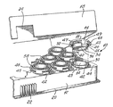
本発明の好ましい実施態様を示す添付図面のうち、図1は、複数のウェル14を形成したトレーまたはベースプレートと、対応ののキャップ16とから成るキャップとウェルとの集合体10の斜視図である。集合体10は、出荷または貯蔵用のカバー18をも含む。カバー18の好ましい形態としでは、キャップに触れずにカバーを固定できるように、カバー18の各隅部に挿入部(図示しない)を設ける。カバー18を使用すれば、数枚の実験トレーを重ねて貯蔵することができる。トレー12はその4つの側壁に沿って延設された縁20を有し、対向する2つの側壁には、オペレーターがトレーを取り扱い易いように、米国特許第4,038,149号に記載されているようなフィンガーグリップ面22をも有する。フィンガーグリップ面22は事故を避け、カバーされている状態でも、カバーを外された状態でも、トレーの取り扱いを著しく容易にする。カバー18は、フィンガーグリップ面22と係合して正しく集合体10に嵌着する切欠き24を有する。
【0026】
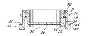
図2は、キャップ16の断面図である。図示のように、キャップ16は、弾性材から成るO−リング素子28が挿入される円筒状スロット26を有する。この弾性材は、特に規定はないが、キャップ16をウェル14の上縁30に嵌着する際に適当な密封効果を発揮する。スロット26の内面32は、平坦面36を越えて突出して空洞部38を形成する部分または突条34を有する。面36は、凸面または凹面でもよいが、図2に示されるような平坦な構造であることが好ましい。上述のように、キャップ16の材質は、結晶の観察および/または操作のため、顕微鏡下に直接置くことができる、充分に透明または半透明である。
【0027】
各キャップ16は、直径を挟んで対向し、突条部41を含む1対のロック素子40を有する。キャップ16は下方に一連のスペーサー45を設けた縁46をも含む。沈殿溶液がウェル14に注入されると、オペレーターは平坦面の上でキャップ16を逆さにし、高分子含有溶液滴を面36に配置する。次いで、キャップ16を慎重に操作して、トレー12の頂面44に設けた対応の孔42に各ロック素子40を、ウェル14の上縁30がスロット26内のO−リング28と当接するまで挿入する。次いで、キャップ16を回動し、孔42の幅より狭く、ウェル14の周縁の一部に沿って形成されているスロット43内へ各ロック素子40を、部分41の頂面全体が頂面44の下に来てウェルを密封し、キャップ16を位置固定するまで摺動させる。最も好ましい実施態様としては、突条部41の部分47をテーパすることによって、頂面44の下へ摺動し易くする。キャップのロックと位置固定をさらに確実にするため、突条部41が面44の下へ完全に挿入された後、面44の下に存在する(図示しない)対応の凹部に嵌入する(図示しない)小突起を部分49に設ける。
【0028】
ウェル14に対するキャップ16の着脱には、図3および4に示すような工具48を使用すればよい。工具48は、オペレーターまたは自動アームが把持し易いように形成された部分52と、縁46の円周よりもやや大きい円周の外面57と縁46の円周よりもやや小さい円周の内面59とを有する円筒部54とから成る本体50を有する。工具48は、直径を挟んで対向する2つのキャップ把持素子60をも含み、各把持素子60は把持フィンガー62を具備する。把持素子60は内面59に、または縁66に直接、または外面57に設けることができる。使用に際しては、各フィンガー62を縁46に形成されているスロット64へ、少なくとも各素子60の部分65が縁46と当接するまで挿入して工具48をキャップ16に重ね合わせる。次いで、把持フィンガー62が縁46の下面と完全に係合するまで工具48を回動し、ロック素子40がスロット42と整列するまで回動し続ける。ここでキャップ16を引き上げる。キャップ16を元の位置に戻すには、上記手順を逆の順序で行なえばよい。部分52の外面53は、テーブルまたは顕微鏡の下に安定状態に置き、オペレーターが結晶を観察および/または操作できるように、平坦でなければならない。顕微鏡下で直接観察および/操作できるためには、面53に、好ましくは円筒部54の内径に対応する開口を設けねばならない(図4参照)。
【0029】
図5は、本発明の他の実施態様を示す。キャップとウェルとの集合体100は、複数のウェル112を形成したトレーまたはベースプレート(図示しない)と、弾性材から成るO−リング素子118が挿入されるおよび円筒状スロット116を有する対応のキャップ114から成る。先に述べた実施態様と同様に、任意ではあるが、適正な密封効果を得るため、O−リングを設ける。
【0030】
各キャップ114は、直径を挟んで対向し、且つ突条部122を有する1対のロック素子120を含む。トレーの頂面126に設けた対応の孔124にそれぞれのロック素子120を、キャップ114の底面128がトレー頂面126と重なるまで挿入することによって、キャップ114をトレーに位置固定する。次いで、キャップ114を回動して、ロック素子120を、孔124の幅よりも小さく、且つウェル112の周縁の一部に沿って延設されているスロット130内へ、突状部122の頂面全体が頂面126の下に来るまで摺動させることにより、ウェルを有効に密封すると共にキャップ114を位置固定する。
【0031】
図6は、本発明の他の簡単な実施態様を示し、この実施態様では、ウェル150の頂面152が円周方向にスロット154を有し、キャップ158に結合されたO−リング素子156がこのスロット154に嵌着される。スロット154の断面積は素子156の断面積よりも小さいから、素子156をスロットに挿入すると、接着剤やグリースを使用しなくても、キャップ158をウェル150にロックするだけで密封状態が得られる。
【0032】
図7は、キャップ170をウェル172に螺着するように構成された、本発明のさらに他の実施態様を示す。この構成もまた、図1、2および5の構成と同様に、解放位置とロック位置との間を移動できるように、キャップのロック機構とウェルとが漸次係合する。
【0033】
本発明のキャップとウェルとの集合体は、特に懸滴結晶化方法にも座滴結晶化方法にも好適である。座滴結晶化方法については、具体的に図示しないが、当業者には周知のように、ウェルに公知の滴支持手段を挿入するか、または成形すればよい。このような座滴支持手段の例としては、Hampton Research (Lguna Hills, California) 社が製造販売するガラス製座滴支持ロッド Micro-Bridges(商品名)がある。
【0034】
各ウェルに任意の平衡溶液を慎重に充填する。次に、任意の蛋白質滴をキャップに付着させる。結晶化すべき特定の蛋白質溶液、例えば、清浄剤を含有する低表面張力溶液を使用する場合、最善の結果を得るためには、底面の形状や組織を適宜に変更すればよい。装置への平衡溶液および蛋白質滴添加は手動でも、市販の自動ピペット装置でも行うことができ、溶液に対するキャップの密閉も手動または自動で行なうことができる。
【0035】
本発明を特定の実施態様に関して説明したが、さらなる変更実施態様も可能であり、本願は、本発明の原理に基づく本発明の変更、利用または適応の他、本発明が属する分野において公知または慣用的な手段の範囲ないである限り、且つ上述した必須構成要件に該当する限り、さらには後記する請求の範囲を逸脱しない限り、本明細書の記述とは異なる実施態様をも包含するものである。
【図面の簡単な説明】
【図1】 本発明の第1のキャップとウェルとの集合体の斜視図。
【図2】 キャップの好ましい実施例の断面図。
【図3】 ウェルに対するキャップ着脱手段の斜視図。
【図4】 図3に示した手段の断面図。
【図5】 本発明のキャップとウェルとの集合体の他の実施例の斜視図。
【図6】 キャップとウェルとの集合体のその他の実施例の斜視図。
【図7】 キャップとウェルとの集合体のその他の実施例の斜視図。[0001]
FIELD OF THE INVENTION
The present invention relates to a molecular and polymer crystallization apparatus. Specifically, this apparatus comprises an assembly of wells and caps for growing protein crystals by a known vapor diffusion technique. This device is particularly beneficial in that it is easy to pre-fill the wells prior to use by the operator for transport and handling.
[0002]
BACKGROUND OF THE INVENTION
Crystallography is a very useful tool for scientists and is of great interest in the field of research. Enables accurate and detailed description of the three-dimensional structure of the molecule, which is a great help in understanding the function of the molecule. Crystallography of macromolecules such as proteins is widely used today both academically and industrially.
[0003]
A simple three-dimensional structure of a protein has already been obtained by a crystallization method, but it is not always easy to obtain a crystal from a polymer. For example, the preferred conditions for crystallization of a given molecule require hundreds of experiments, if not thousands. As a result, means and methods have been developed to perform as many experiments as quickly as possible, such as hanging-drop and sitting-drop methods. All of these methods utilize vapor diffusion to obtain crystals.
[0004]
The hanging drop method is most widely used today as a technique for exploring various crystallization conditions for polymers such as proteins. This method involves placing a droplet of about 2-20 μL of a solution containing the polymer to be crystallized and a precipitant on a known precipitation solution such as 20% polyethylene glycol or 40% ammonium sulfate contained in a tank or well. Suspend to. The system is then sealed. After some time, the vapor diffusion of the solvent or solvent mixture reaches equilibrium between the droplet and the solution in the tank. Eventually, the moisture in the droplets decreases, the polymer and precipitant concentrations increase, and the polymer crystallizes under optimal conditions. The technique of performing a hanging drop or sitting drop experiment is a laborious task and must be performed by a skilled operator.
[0005]
Conventionally, commercially available trays made of an inert thermoplastic having a large number of tanks or wells are provided, and the sediment is manually poured into each tank or well. The polymer solution is then suspended on the well by mixing it with the precipitant on a glass plate (cover glass) and turning it over and overlaying the well. Apply grease to the edge of each well to ensure a tight seal before placing the glass plate on the well. Since grease easily contaminates the polymer solution, care must be taken when stacking glass plates on each well. The crystallization method is performed using a microscope. When crystals are obtained, the glass plate is removed. At this time, sufficient care must be taken to prevent contamination by the crystallized polymer grease and / or breakage of the glass plate. Moreover, it is difficult to remove the grease, and a part of the glass plate remains on the glass plate. Therefore, it is difficult to reuse the glass plate regardless of the type of experiment.
[0006]
The advantage of the hanging and sitting drop method is that it allows screening of crystallization conditions and is literally a microcrystal technique. Experiments with relatively small amounts of polymer are possible because the vapor diffusion in the hanging or sitting drop method allows screening of conditions over a wide range. Moreover, the experimental results can be visualized relatively clearly, and the resulting crystals are not restricted at all, i.e. do not adhere to or adhere to any surface.
[0007]
In many cases, hundreds of experiments are required to find the proper crystallization conditions to produce high quality crystals. That is, hanging drop and sitting drop experiments are extremely laborious methods that require skilled operators. For example, it is necessary to perform a step of sucking and injecting the component many times, a step of applying grease, and the like during the experiment. In addition, separate cover glasses for each well need to be manually flipped over and stacked. Since the number of steps is large and complicated, the variation in experimental results increases.
[0008]
As described above, conventionally, grease is used to seal between the well and the cover glass. Other methods for sealing the system have also been proposed. For example, immersion oil or adhesive tape is used instead of grease. As with grease, these sealing means have drawbacks. Applying grease to the upper edge of the well is not always easy and is a time consuming operation. An operator who repeats this work thousands of times can cause physical pain in their hands. Another serious problem or risk arises when manipulating crystals on a greased cover slide. The cover slide can break during the operation, which not only loses crystals but can also injure the operator. There are also problems with immersion oil. That is, a certain amount of immersion oil must be used. When the amount used is too large, the inside of the well is contaminated, and when the amount is insufficient, the sealed state cannot be obtained and the precipitated solution evaporates. Adhesive tape is quick and easy to handle, but all experiments are sealed at the end of the setup, resulting in variability in experimental results between the first and 24th drops. Also, the crystals adhere to the tape, making it impossible to collect the crystals, and there is a problem in the operation of collecting the drops.
[0009]
These issues have facilitated method automation. Such an automatic crystallization apparatus already exists. The well-known Cyberlab-200 (trade name) device injects solution into wells, applies grease to the upper edge of each well, drops droplets onto a cover slide held by a vacuum arm, and covers the well. Place the slide. However, this device also has some drawbacks. That is, the assembly of experimental equipment is complicated and the use of grease is inevitable. Moreover, this device is extremely expensive.
[0010]
Related literature includes the following: U.S. Pat. No. 2,366,886; U.S. Pat. No. 3,107,204; U.S. Pat. No. 3,297,184; U.S. Pat. No. 3,537,956; U.S. Pat. No. 3,597,326; US Pat. No. 3,649,464; US Pat. No. 3,692,498; US Pat. No. 3,729,382; US Pat. No. 3,745,091; US Pat. No. 3,907,505; U.S. Patent No. 4,038,149; U.S. Patent No. 4,154,795; U.S. Patent No. 4,495,289; U.S. Patent No. 4,917,707; U.S. Patent No. 5,271,795.
[0011]
Therefore, development of a polymer crystallization apparatus that overcomes the above disadvantages is eagerly desired. This device preferably does not require external means such as grease, dipping oil or adhesive tape to seal the well and cover and can be easily operated either manually or automatically. Ultimately, it is preferred that the assembly of the device be significantly easier and faster while at the same time eliminating the risk of contamination of the resulting crystals. Finally, the apparatus must be available for various crystallization methods such as hanging drop or sitting drop methods.
[0012]
SUMMARY OF THE INVENTION
The present invention comprises a tray comprising a top surface, a bottom surface, an upstanding peripheral wall extending from the top surface to the bottom surface, and a plurality of wells extending downward from the top surface and opening in the top surface for receiving a precipitation solution; And a cap having a locking member for locking each well in a sealed state. Such trays are particularly useful for growing molecules and polymer crystals.
[0013]
DETAILED DESCRIPTION OF THE INVENTION
An object of the present invention is to provide a crystal forming apparatus using a vapor diffusion method. This device consists of a well and a transparent cap that closes the well to form a sealed space, and the well is sealed without adding a sealing material such as grease, oil, adhesive tape, etc. between the cap. . The cap is formed of a transparent material that allows observation of the crystal growth under a microscope and manipulation of the crystal. This apparatus is therefore advantageous in macromolecular crystal growth methods, particularly in hanging-drop and sitting-drop cultures.
[0014]
Since the equipment is simple, a well-trained operator is required to seal the well by filling the well with a precipitating solution, attaching a polymer solution drop to the cap, and fitting the cap to the well. Can do enough.
[0015]
In a preferred embodiment of the present invention, a plurality of, for example, 4 × 6 wells are formed on each tray, and a corresponding number of transparent caps are fitted into the wells. The resulting tray and cap may be treated with a hydrophobic agent, such as a silicon treating agent, as necessary.
[0016]
Since the cap and well bottom are transparent, crystallization can be traced with minimal handling and without disturbing the vapor balance in each well. Furthermore, since the cap is made of a transparent or translucent material, that is, a clear material, it is easy to visualize the results under a microscope.
[0017]
The material of the tray and the cap is preferably the same and can be easily formed at an appropriate cost. The material must be stable over time for the various chemicals present in the well and on the cap. It is also desirable that the material does not absorb water and has excellent optical properties that facilitate operation and observation under a microscope. Suitable materials include polystyrene, polypropylene, polycarbonate, polyacrylate, polymethacrylate, acrylonitrile-styrene copolymer, nitrile-acrylonitrile-styrene copolymer, polyphenylene oxide, phenoxy resin, and the most preferred materials. Polystyrene.
[0018]
Another object of the present invention is to provide a crystal forming apparatus in which a grown crystal can be operated under a microscope without being transferred from a cap, and a solution can be directly added in an environment without grease without transferring a crystal. .
[0019]
Another important advantage of the device of the present invention is that once a series of experiments is completed, the tray can be reused simply by removing another cap group containing a solution drop containing the polymer to be crystallized and attaching it to the well. . A given cap can also be removed from the first well and locked to another well containing a different precipitation solution.
[0020]
The present invention also provides a method for forming a polymer crystal comprising the steps of injecting a precipitation solution into a well; forming a droplet in a cap that includes a locking member that locks the cap to the well; and locking and sealing the well. Related. In a preferred embodiment, a ring made of an elastomer material such as polypropylene, ethylene-propylene copolymer, Teflon (trade name) or the like is preferably interposed between the cap and the well. In another preferred embodiment, pre-filled and sealed wells are manufactured and a tray is provided to the operator so that it is “ready to use”.
[0021]
In view of the ergonomic properties of the present invention, the cap is easy to fit and does not require the special dexterity associated with the use of conventional thin and fragile microscope cover glasses. Since there is a recess in the cap surface facing the well bottom, after placing the cap upside down on the table, the liquid can be added directly onto the drop without transferring the crystal to another well and is therefore brittle An operation that leads to the destruction of the crystal is not necessary.
[0022]
The use of the assembly of the cap and well of the present invention can be easily automated by providing a simple gripping element at the end of the automatic arm and providing a structure for releasably gripping the cap. There is no need to apply grease or manipulate fragile coverglasses. The gripping element can also be manually operated by an operator, as will be described later.
[0023]
The cap and well assembly of the present invention can also be used in fields such as cell culture, molecular biology or cell biology.
[0024]
In the most preferred embodiment of the invention, the wells are prefilled and sealed with a cap. Thus, the operator will receive a “ready to use” assembly and the laborious work of filling the individual wells with the appropriate precipitation solution is eliminated. That is, the purchaser may order the required number of assemblies together with one or several types of precipitation solutions. At the time of shipment, a film may be used instead of the cap of the assembly in order to prevent the precipitation solution from coming into contact with the cap. When such contact occurs, the cap needs to be cleaned prior to use. It is also possible to use a cap exclusively for shipment and use another cap for the experiment. Whether shipping pre-filled wells or experiments, it is important to ensure that the wells are sealed in order to prevent the precipitation solution from evaporating or spilling.
[0025]
FIG. 1 is a perspective view of a cap and well assembly 10 comprising a tray or base plate in which a plurality of
[0026]
FIG. 2 is a cross-sectional view of the
[0027]
Each
[0028]
A
[0029]
FIG. 5 shows another embodiment of the present invention. The cap-
[0030]
Each
[0031]
FIG. 6 shows another simple embodiment of the invention in which the
[0032]
FIG. 7 illustrates yet another embodiment of the present invention configured to thread the
[0033]
The assembly of the cap and well of the present invention is particularly suitable for both the hanging drop crystallization method and the sitting drop crystallization method. Although the method for crystallizing the sessile droplets is not specifically shown, a well-known droplet support means may be inserted into the well or formed as is well known to those skilled in the art. An example of such a droplet support means is a glass droplet support rod Micro-Bridges (trade name) manufactured and sold by Hampton Research (Lguna Hills, California).
[0034]
Carefully fill each well with any equilibration solution. Next, an arbitrary protein droplet is attached to the cap. In the case of using a specific protein solution to be crystallized, for example, a low surface tension solution containing a detergent, the shape and structure of the bottom surface may be appropriately changed in order to obtain the best results. The equilibration solution and protein drop addition to the device can be performed manually or with a commercially available automatic pipetting device, and the cap can be sealed manually or automatically with respect to the solution.
[0035]
Although the present invention has been described with respect to particular embodiments, further modified embodiments are possible and the present application is known or commonly used in the field to which the present invention belongs, as well as modifications, uses or adaptations of the present invention based on the principles of the present invention. It is intended to include embodiments different from those described in the present specification as long as they do not fall within the scope of the essential means, and fall within the scope of the claims described below, as long as the above-described essential constituent elements are satisfied. .
[Brief description of the drawings]
FIG. 1 is a perspective view of an assembly of a first cap and a well according to the present invention.
FIG. 2 is a cross-sectional view of a preferred embodiment of the cap.
FIG. 3 is a perspective view of a cap attaching / detaching means for a well.
4 is a cross-sectional view of the means shown in FIG.
FIG. 5 is a perspective view of another embodiment of the cap and well assembly of the present invention.
FIG. 6 is a perspective view of another embodiment of an assembly of a cap and a well.
FIG. 7 is a perspective view of another embodiment of an assembly of a cap and a well.
Claims (20)
底壁および前記底壁から延びてトレー上面を支える垂直な周壁を有するトレー、A tray having a bottom wall and a vertical peripheral wall extending from the bottom wall and supporting the top surface of the tray;
沈澱溶液を保持するための、上部開口および光透過性の底を有し且つ前記トレー上面によって支持されている多数のウェル、A number of wells having a top opening and a light transmissive bottom and supported by the top surface of the tray for holding the precipitation solution;
前記ウェルそれぞれの前記上部開口をカバーして密閉しそして前記ウェルそれぞれの内部における結晶化を支持するための個別に取外し自在なキャップであって、それぞれが、結晶化すべき分子または高分子を含有する溶液の小滴をそれぞれのウェル内に含まれる前記沈澱溶液上に懸垂させるための前記ウェルに面する透明な支持面を内側に有する空洞を形成する前記キャップ、ならびにIndividually removable caps that cover and seal the top opening of each of the wells and support crystallization within each of the wells, each containing a molecule or macromolecule to be crystallized The cap forming a cavity having a transparent support surface on the inside facing the well for suspending droplets of the solution on the precipitation solution contained in each well; and
前記キャップそれぞれと前記ウェルそれぞれとの間を密封する手段Means for sealing between each cap and each well
を含み、Including
前記キャップは、オペレーターが前記キャップと前記ウェルとの間に外部的な密封材を塗布しなくても、前記空洞の外側の位置において、前記キャップを前記ウェルに解放自在に密封状態にロックするように、前記ウェルのそれぞれの内面が有する対応の第2のネジ式ロック部材に対して構造的に係合可能な一体的第1ネジ式ロック部材を外面に有し、The cap releasably locks the cap to the well in a releasable manner at a position outside the cavity without an operator applying an external sealant between the cap and the well. Each having an integral first threaded locking member on the outer surface that is structurally engageable with a corresponding second threaded locking member on each inner surface of the well;
前記光透過性の底と前記透明な支持面との組み合わせが、前記ウェル内の結晶の生長を顕微鏡下で前記支持面を通して観察およびモニタリングすることを可能とすることを特徴とする前記装置。The device characterized in that the combination of the light transmissive bottom and the transparent support surface allows the growth of crystals in the well to be observed and monitored through the support surface under a microscope.
Applications Claiming Priority (3)
| Application Number | Priority Date | Filing Date | Title |
|---|---|---|---|
| CA002261326A CA2261326A1 (en) | 1999-02-09 | 1999-02-09 | Laboratory cap and well for hanging-drop crystallization methods |
| CA2,261,326 | 1999-02-09 | ||
| PCT/CA2000/000119 WO2000047323A1 (en) | 1999-02-09 | 2000-02-09 | Laboratory cap and well for hanging-drop crystallization methods |
Publications (3)
| Publication Number | Publication Date |
|---|---|
| JP2002536255A JP2002536255A (en) | 2002-10-29 |
| JP2002536255A5 JP2002536255A5 (en) | 2007-02-15 |
| JP4753107B2 true JP4753107B2 (en) | 2011-08-24 |
Family
ID=4163275
Family Applications (1)
| Application Number | Title | Priority Date | Filing Date |
|---|---|---|---|
| JP2000598269A Expired - Lifetime JP4753107B2 (en) | 1999-02-09 | 2000-02-09 | Laboratory cap and well for hanging drop crystallization method |
Country Status (11)
| Country | Link |
|---|---|
| US (2) | US7316805B1 (en) |
| EP (1) | EP1148946B1 (en) |
| JP (1) | JP4753107B2 (en) |
| KR (1) | KR20020013837A (en) |
| AT (1) | ATE266474T1 (en) |
| AU (1) | AU773384C (en) |
| CA (1) | CA2261326A1 (en) |
| DE (1) | DE60010657T2 (en) |
| DK (1) | DK1148946T3 (en) |
| IL (1) | IL144752A (en) |
| WO (1) | WO2000047323A1 (en) |
Families Citing this family (17)
| Publication number | Priority date | Publication date | Assignee | Title |
|---|---|---|---|---|
| US6797461B2 (en) | 2000-10-27 | 2004-09-28 | Promega Corporation | Tryptase substrates and assay for tryptase activity using same |
| JP3905399B2 (en) | 2002-02-25 | 2007-04-18 | プロテインウエーブ株式会社 | Biopolymer crystal generator |
| US20030235519A1 (en) * | 2002-06-24 | 2003-12-25 | Corning Incorporated | Protein crystallography hanging drop lid that individually covers each of the wells in a microplate |
| US7112241B2 (en) | 2002-12-31 | 2006-09-26 | Corning Incorporated | Protein crystallography hanging drop multiwell plate |
| CN100448503C (en) * | 2003-01-17 | 2009-01-07 | 纳克斯泰尔生物技术公司 | Pre-filled crystallization plates and methods for making and using same |
| MXPA05007619A (en) | 2003-01-17 | 2005-10-26 | Nextal Biotechnologie Inc | Pre-filled crystallization plates and methods for making and using same. |
| JP2008506616A (en) * | 2004-07-16 | 2008-03-06 | ネクスタル バイオテクノロジー インコーポレイテッド | Method and apparatus for optimizing substrate crystallization conditions |
| KR101570545B1 (en) * | 2007-03-09 | 2015-11-19 | 넥서스 바이오시스템즈, 인코포레이티드. | Device and method for removing a peelable seal |
| US20130295575A1 (en) * | 2011-01-20 | 2013-11-07 | 4Titude Limited | Microplate and multiwell strip with double rimmed wells |
| US10175183B2 (en) | 2011-03-31 | 2019-01-08 | Kunimine Industries Co., Ltd. | Agent for searching for protein crystallization conditions and method of searching for protein crystallization conditions |
| US9075039B2 (en) | 2011-11-08 | 2015-07-07 | Becton, Dickinson And Company | Container and cap for a biological specimen |
| US9381524B2 (en) | 2011-11-08 | 2016-07-05 | Becton, Dickinson And Company | System and method for automated sample preparation |
| US9180461B2 (en) * | 2012-10-22 | 2015-11-10 | Qiagen Gaithersburg, Inc. | Condensation-reducing incubation cover |
| DE102013011534B4 (en) | 2013-07-10 | 2015-09-03 | Fraunhofer-Gesellschaft zur Förderung der angewandten Forschung e.V. | Culture vessel and method for culturing biological cells in hanging drops |
| JP6957493B2 (en) | 2016-03-02 | 2021-11-02 | ベクトン・ディキンソン・アンド・カンパニーBecton, Dickinson And Company | Packaging and equipment for accessing screw cap containers in automated systems |
| GB201705870D0 (en) * | 2017-04-11 | 2017-05-24 | 4Titude Ltd | Improved sealing mat |
| FR3083785B1 (en) * | 2018-07-10 | 2020-06-19 | Technoflex | HOLDING DEVICE FOR CONTAINERS HAVING A FILLING HOSE AND USE OF SAID DEVICE |
Citations (4)
| Publication number | Priority date | Publication date | Assignee | Title |
|---|---|---|---|---|
| US4599314A (en) * | 1983-06-14 | 1986-07-08 | Hsc Research Development Corporation | Multiple vessel specimen tray with lid for releasably adhering vessel covers |
| US4829006A (en) * | 1988-02-01 | 1989-05-09 | Difco Laboratories | Centrifugation vial and cluster tray |
| WO1993007311A1 (en) * | 1991-10-09 | 1993-04-15 | Schering Corporation | Crystal forming device and automated crystallization system |
| US5846489A (en) * | 1994-04-09 | 1998-12-08 | Boehringer Mannheim Gmbh | System for opening closures of vessels and for the contamination-free operation of reaction sequences |
Family Cites Families (23)
| Publication number | Priority date | Publication date | Assignee | Title |
|---|---|---|---|---|
| US2366886A (en) | 1942-11-20 | 1945-01-09 | American Tag Company | Capsule handling apparatus |
| US3107204A (en) | 1961-01-23 | 1963-10-15 | Dalde Reagents Inc | Microbiological testing method and structure therefor |
| US3297184A (en) * | 1963-11-05 | 1967-01-10 | B D Lab Inc | Cap for culture tubes |
| US3537956A (en) | 1967-06-26 | 1970-11-03 | Joseph R Falcone | Petrie dish |
| US3597326A (en) | 1968-07-26 | 1971-08-03 | John Liner | Multi-dish laboratory unit |
| US3649464A (en) | 1969-12-05 | 1972-03-14 | Microbiological Ass Inc | Assay and culture tray |
| US3692498A (en) | 1970-10-12 | 1972-09-19 | Lab Aids Inc | Chemical testing apparatus |
| US3745091A (en) | 1970-11-18 | 1973-07-10 | Miles Lab | Biological reaction chamber apparatus |
| US3729382A (en) | 1970-12-09 | 1973-04-24 | Becton Dickinson Co | Microorganism sampling dish |
| US3907505A (en) | 1973-05-30 | 1975-09-23 | Miles Lab | Selectively detachable apparatus |
| US3860136A (en) * | 1974-01-30 | 1975-01-14 | Child Resistant Packaging Inc | Child-resistant enclosure for hazardous materials |
| US4038149A (en) * | 1975-12-31 | 1977-07-26 | Linbro Scientific, Inc. | Laboratory trays with lockable covers |
| US4154795A (en) | 1976-07-23 | 1979-05-15 | Dynatech Holdings Limited | Microtest plates |
| US4495289A (en) | 1981-03-17 | 1985-01-22 | Data Packaging Corporation | Tissue culture cluster dish |
| DE3402276C1 (en) * | 1984-01-24 | 1985-02-21 | Eppendorf Gerätebau Netheler + Hinz GmbH, 2000 Hamburg | Plastic reaction vessel for small amounts of liquid |
| FR2604917B1 (en) | 1986-10-09 | 1989-01-27 | Aerospatiale | CRYSTALLOGENESIS METHOD, CELL AND DEVICE, ESPECIALLY BY SPACE VESSEL |
| JPH04124082A (en) | 1990-09-14 | 1992-04-24 | Agency Of Ind Science & Technol | Formation of crystal |
| KR100236506B1 (en) * | 1990-11-29 | 2000-01-15 | 퍼킨-엘머시터스인스트루먼츠 | Apparatus for polymerase chain reaction |
| US5221410A (en) * | 1991-10-09 | 1993-06-22 | Schering Corporation | Crystal forming device |
| US5342581A (en) * | 1993-04-19 | 1994-08-30 | Sanadi Ashok R | Apparatus for preventing cross-contamination of multi-well test plates |
| US5419278A (en) * | 1994-05-25 | 1995-05-30 | Carter; Daniel C. | Vapor equilibration tray for growing protein crystals |
| US6074614A (en) * | 1995-06-07 | 2000-06-13 | Molecular Devices Corporation | Multi-assay plate cover for elimination of meniscus |
| US6027694A (en) * | 1996-10-17 | 2000-02-22 | Texperts, Inc. | Spillproof microplate assembly |
-
1999
- 1999-02-09 CA CA002261326A patent/CA2261326A1/en not_active Abandoned
-
2000
- 2000-02-09 WO PCT/CA2000/000119 patent/WO2000047323A1/en not_active Application Discontinuation
- 2000-02-09 DE DE60010657T patent/DE60010657T2/en not_active Expired - Lifetime
- 2000-02-09 EP EP00903455A patent/EP1148946B1/en not_active Expired - Lifetime
- 2000-02-09 AT AT00903455T patent/ATE266474T1/en not_active IP Right Cessation
- 2000-02-09 AU AU25291/00A patent/AU773384C/en not_active Expired
- 2000-02-09 DK DK00903455T patent/DK1148946T3/en active
- 2000-02-09 IL IL14475200A patent/IL144752A/en not_active IP Right Cessation
- 2000-02-09 JP JP2000598269A patent/JP4753107B2/en not_active Expired - Lifetime
- 2000-02-09 KR KR1020017010078A patent/KR20020013837A/en not_active Application Discontinuation
- 2000-09-02 US US09/913,088 patent/US7316805B1/en not_active Expired - Lifetime
-
2007
- 2007-04-05 US US11/784,157 patent/US20070184551A1/en not_active Abandoned
Patent Citations (4)
| Publication number | Priority date | Publication date | Assignee | Title |
|---|---|---|---|---|
| US4599314A (en) * | 1983-06-14 | 1986-07-08 | Hsc Research Development Corporation | Multiple vessel specimen tray with lid for releasably adhering vessel covers |
| US4829006A (en) * | 1988-02-01 | 1989-05-09 | Difco Laboratories | Centrifugation vial and cluster tray |
| WO1993007311A1 (en) * | 1991-10-09 | 1993-04-15 | Schering Corporation | Crystal forming device and automated crystallization system |
| US5846489A (en) * | 1994-04-09 | 1998-12-08 | Boehringer Mannheim Gmbh | System for opening closures of vessels and for the contamination-free operation of reaction sequences |
Also Published As
| Publication number | Publication date |
|---|---|
| US7316805B1 (en) | 2008-01-08 |
| ATE266474T1 (en) | 2004-05-15 |
| IL144752A (en) | 2005-03-20 |
| DK1148946T3 (en) | 2004-08-09 |
| AU773384C (en) | 2004-12-23 |
| WO2000047323A1 (en) | 2000-08-17 |
| EP1148946B1 (en) | 2004-05-12 |
| US20070184551A1 (en) | 2007-08-09 |
| DE60010657D1 (en) | 2004-06-17 |
| JP2002536255A (en) | 2002-10-29 |
| KR20020013837A (en) | 2002-02-21 |
| EP1148946A1 (en) | 2001-10-31 |
| CA2261326A1 (en) | 2000-08-09 |
| IL144752A0 (en) | 2002-06-30 |
| DE60010657T2 (en) | 2005-02-10 |
| AU773384B2 (en) | 2004-05-27 |
| AU2529100A (en) | 2000-08-29 |
Similar Documents
| Publication | Publication Date | Title |
|---|---|---|
| US20070184551A1 (en) | Crystallization Methods for laboratory cap and well | |
| US5096676A (en) | Crystal growing apparatus | |
| US5419278A (en) | Vapor equilibration tray for growing protein crystals | |
| US5221410A (en) | Crystal forming device | |
| US6656267B2 (en) | Tray for macromolecule crystallization and method of using the same | |
| US5400741A (en) | Device for growing crystals | |
| US7993416B2 (en) | Pre-filled crystallization plates and methods for making and using same | |
| US5641681A (en) | Device and method for screening crystallization conditions in solution crystal growth | |
| US10308381B2 (en) | Cap supply for vessels containing biological samples | |
| CA2120744A1 (en) | Crystal forming device and automated crystallization system | |
| JPH06237758A (en) | Culture container | |
| US5409667A (en) | Tube rack | |
| JP2019507072A (en) | Packaging and apparatus for accessing screw cap containers in automated systems | |
| Ducruix et al. | Methods of crystallization | |
| CA2360315C (en) | Laboratory cap and well for hanging-drop crystallization methods | |
| MXPA01008052A (en) | Laboratory cap and well for hanging-drop crystallization methods | |
| US20110046022A1 (en) | Crystallization device for high-throughput visual inspection and x-ray diffraction analysis | |
| WO2004029338A1 (en) | Dialysis apparatus | |
| CN1852755A (en) | Pre-filled crystallization plates and methods for making and using same | |
| JP3958610B2 (en) | Polymer crystallization vessel | |
| US20030015132A1 (en) | Stackable vapor-equilibration tray for cell culture and protein crystal growth |
Legal Events
| Date | Code | Title | Description |
|---|---|---|---|
| A521 | Request for written amendment filed |
Free format text: JAPANESE INTERMEDIATE CODE: A523 Effective date: 20061220 |
|
| A621 | Written request for application examination |
Free format text: JAPANESE INTERMEDIATE CODE: A621 Effective date: 20061220 |
|
| A131 | Notification of reasons for refusal |
Free format text: JAPANESE INTERMEDIATE CODE: A131 Effective date: 20090818 |
|
| A601 | Written request for extension of time |
Free format text: JAPANESE INTERMEDIATE CODE: A601 Effective date: 20091118 |
|
| A602 | Written permission of extension of time |
Free format text: JAPANESE INTERMEDIATE CODE: A602 Effective date: 20091126 |
|
| A521 | Request for written amendment filed |
Free format text: JAPANESE INTERMEDIATE CODE: A523 Effective date: 20091209 |
|
| A02 | Decision of refusal |
Free format text: JAPANESE INTERMEDIATE CODE: A02 Effective date: 20100601 |
|
| A61 | First payment of annual fees (during grant procedure) |
Free format text: JAPANESE INTERMEDIATE CODE: A61 Effective date: 20110512 |
|
| FPAY | Renewal fee payment (event date is renewal date of database) |
Free format text: PAYMENT UNTIL: 20140603 Year of fee payment: 3 |
|
| R150 | Certificate of patent or registration of utility model |
Ref document number: 4753107 Country of ref document: JP Free format text: JAPANESE INTERMEDIATE CODE: R150 Free format text: JAPANESE INTERMEDIATE CODE: R150 |
|
| R250 | Receipt of annual fees |
Free format text: JAPANESE INTERMEDIATE CODE: R250 |
|
| R250 | Receipt of annual fees |
Free format text: JAPANESE INTERMEDIATE CODE: R250 |
|
| R250 | Receipt of annual fees |
Free format text: JAPANESE INTERMEDIATE CODE: R250 |
|
| R250 | Receipt of annual fees |
Free format text: JAPANESE INTERMEDIATE CODE: R250 |
|
| R250 | Receipt of annual fees |
Free format text: JAPANESE INTERMEDIATE CODE: R250 |
|
| R250 | Receipt of annual fees |
Free format text: JAPANESE INTERMEDIATE CODE: R250 |
|
| EXPY | Cancellation because of completion of term |