JP4740993B2 - Optical disc and manufacturing method thereof, and data recording method and reproducing method using the optical disc - Google Patents
Optical disc and manufacturing method thereof, and data recording method and reproducing method using the optical disc Download PDFInfo
- Publication number
- JP4740993B2 JP4740993B2 JP2008319943A JP2008319943A JP4740993B2 JP 4740993 B2 JP4740993 B2 JP 4740993B2 JP 2008319943 A JP2008319943 A JP 2008319943A JP 2008319943 A JP2008319943 A JP 2008319943A JP 4740993 B2 JP4740993 B2 JP 4740993B2
- Authority
- JP
- Japan
- Prior art keywords
- information recording
- area
- recording layer
- recording
- learning
- Prior art date
- Legal status (The legal status is an assumption and is not a legal conclusion. Google has not performed a legal analysis and makes no representation as to the accuracy of the status listed.)
- Active
Links
Images


Classifications
-
- G—PHYSICS
- G11—INFORMATION STORAGE
- G11B—INFORMATION STORAGE BASED ON RELATIVE MOVEMENT BETWEEN RECORD CARRIER AND TRANSDUCER
- G11B7/00—Recording or reproducing by optical means, e.g. recording using a thermal beam of optical radiation by modifying optical properties or the physical structure, reproducing using an optical beam at lower power by sensing optical properties; Record carriers therefor
- G11B7/007—Arrangement of the information on the record carrier, e.g. form of tracks, actual track shape, e.g. wobbled, or cross-section, e.g. v-shaped; Sequential information structures, e.g. sectoring or header formats within a track
-
- G—PHYSICS
- G11—INFORMATION STORAGE
- G11B—INFORMATION STORAGE BASED ON RELATIVE MOVEMENT BETWEEN RECORD CARRIER AND TRANSDUCER
- G11B7/00—Recording or reproducing by optical means, e.g. recording using a thermal beam of optical radiation by modifying optical properties or the physical structure, reproducing using an optical beam at lower power by sensing optical properties; Record carriers therefor
- G11B7/12—Heads, e.g. forming of the optical beam spot or modulation of the optical beam
- G11B7/125—Optical beam sources therefor, e.g. laser control circuitry specially adapted for optical storage devices; Modulators, e.g. means for controlling the size or intensity of optical spots or optical traces
- G11B7/126—Circuits, methods or arrangements for laser control or stabilisation
- G11B7/1267—Power calibration
-
- G—PHYSICS
- G11—INFORMATION STORAGE
- G11B—INFORMATION STORAGE BASED ON RELATIVE MOVEMENT BETWEEN RECORD CARRIER AND TRANSDUCER
- G11B7/00—Recording or reproducing by optical means, e.g. recording using a thermal beam of optical radiation by modifying optical properties or the physical structure, reproducing using an optical beam at lower power by sensing optical properties; Record carriers therefor
- G11B7/007—Arrangement of the information on the record carrier, e.g. form of tracks, actual track shape, e.g. wobbled, or cross-section, e.g. v-shaped; Sequential information structures, e.g. sectoring or header formats within a track
- G11B7/00736—Auxiliary data, e.g. lead-in, lead-out, Power Calibration Area [PCA], Burst Cutting Area [BCA], control information
-
- G—PHYSICS
- G11—INFORMATION STORAGE
- G11B—INFORMATION STORAGE BASED ON RELATIVE MOVEMENT BETWEEN RECORD CARRIER AND TRANSDUCER
- G11B7/00—Recording or reproducing by optical means, e.g. recording using a thermal beam of optical radiation by modifying optical properties or the physical structure, reproducing using an optical beam at lower power by sensing optical properties; Record carriers therefor
- G11B7/24—Record carriers characterised by shape, structure or physical properties, or by the selection of the material
- G11B7/2403—Layers; Shape, structure or physical properties thereof
- G11B7/24035—Recording layers
- G11B7/24038—Multiple laminated recording layers
-
- G—PHYSICS
- G11—INFORMATION STORAGE
- G11B—INFORMATION STORAGE BASED ON RELATIVE MOVEMENT BETWEEN RECORD CARRIER AND TRANSDUCER
- G11B7/00—Recording or reproducing by optical means, e.g. recording using a thermal beam of optical radiation by modifying optical properties or the physical structure, reproducing using an optical beam at lower power by sensing optical properties; Record carriers therefor
- G11B2007/0003—Recording, reproducing or erasing systems characterised by the structure or type of the carrier
- G11B2007/0009—Recording, reproducing or erasing systems characterised by the structure or type of the carrier for carriers having data stored in three dimensions, e.g. volume storage
- G11B2007/0013—Recording, reproducing or erasing systems characterised by the structure or type of the carrier for carriers having data stored in three dimensions, e.g. volume storage for carriers having multiple discrete layers
-
- G—PHYSICS
- G11—INFORMATION STORAGE
- G11B—INFORMATION STORAGE BASED ON RELATIVE MOVEMENT BETWEEN RECORD CARRIER AND TRANSDUCER
- G11B7/00—Recording or reproducing by optical means, e.g. recording using a thermal beam of optical radiation by modifying optical properties or the physical structure, reproducing using an optical beam at lower power by sensing optical properties; Record carriers therefor
- G11B7/004—Recording, reproducing or erasing methods; Read, write or erase circuits therefor
- G11B7/0045—Recording
Description
本発明は、複数の情報記録層を含み、少なくとも二つの情報記録層に最適な記録条件を求めるための記録学習領域が設けられた光ディスク及びその製造方法と、この光ディスクを用いたデータの記録方法及び再生方法とに関する。 The present invention relates to an optical disc including a plurality of information recording layers, in which a recording learning area is provided for obtaining optimum recording conditions in at least two information recording layers, a manufacturing method thereof, and a data recording method using the optical disc And a reproduction method.
近年、光ディスクの高密度化、大容量化が進んでおり、光ディスクの信頼性を確保することが重要になっている。そこで、信頼性を確保するため、光ディスクに記録学習領域を設け、この記録学習領域に試し記録を行うことにより記録条件を求める記録学習処理を行う技術が提案されている(例えば、特許文献1参照。)。記録学習とは、記録時に光ディスクに照射されるレーザ光に関するパルス条件を最適化する動作のことである。パルス条件には、例えば、記録時に光ディスクに照射されるレーザパルスのパワー値、レーザパルスの発生タイミング及び長さ等が含まれる。 In recent years, the density and capacity of optical discs have increased, and it has become important to ensure the reliability of optical discs. Therefore, in order to ensure reliability, a technique has been proposed in which a recording learning area is provided on an optical disc and a recording learning process is performed to obtain a recording condition by performing trial recording in the recording learning area (see, for example, Patent Document 1). .) Recording learning is an operation for optimizing the pulse condition related to the laser beam irradiated to the optical disc during recording. The pulse condition includes, for example, the power value of the laser pulse irradiated to the optical disc during recording, the generation timing and length of the laser pulse, and the like.
また、記録再生用のレーザ光に対して半透明な情報記録層をレーザ光入射側(手前)に配置し、さらに奥に情報記録層を配置して2層化することにより、記録容量を倍増させる光ディスクの開発も盛んである。このような2層型光ディスクにおいても記録学習が必要であり、手前の情報記録層(L1層という。)と奥の情報記録層(L0層という。)のそれぞれについて、データの記録の前に記録条件の学習がなされる技術が提案されている。(例えば、特許文献2参照。)。
しかしながら、上記記録学習動作は、L0層において最適な記録条件の抽出が行われない可能性がある。記録学習では、データを記録するのに適切な記録パワー(最適記録パワー)に比べ、かなり高いパワーでテスト信号を記録することも考えられる。よって、最適記録パワーではL1層の記録の有無がL0層への記録品質に影響を与えないような光ディスクであっても、かなりパワーの高いテスト記録パワーではL1層をレーザ光が通過するときに強度変化などの影響を受けてしまい、記録学習動作によってL0層の最適記録パワーが得られないことが考えられる。 However, in the recording learning operation, there is a possibility that optimum recording conditions are not extracted in the L0 layer. In recording learning, it is also conceivable to record a test signal at a considerably higher power than the recording power appropriate for recording data (optimal recording power). Therefore, even with an optical disc in which the presence / absence of recording on the L1 layer does not affect the recording quality on the L0 layer at the optimum recording power, the laser beam passes through the L1 layer at a test recording power with a considerably high power. It is considered that the optimum recording power of the L0 layer cannot be obtained by the recording learning operation due to the influence of the intensity change or the like.
本発明は、上記課題に鑑みてなされたものであり、記録可能な情報記録層を複数備えた光ディスクにおいて、レーザ光入射側に位置する情報記録層の記録状態にかかわらず、奥の情報記録層においても精度の良い記録学習が可能な光ディスクとその製造方法とを提供し、さらに、この光ディスクを用いたデータの記録方法及び再生方法を提供することを目的とする。 The present invention has been made in view of the above problems, and in an optical disc provided with a plurality of recordable information recording layers, the information recording layer in the back regardless of the recording state of the information recording layer located on the laser beam incident side The present invention also provides an optical disc capable of recording with high accuracy and a manufacturing method thereof, and further provides a data recording method and a reproducing method using the optical disc.
本発明の光ディスクは、複数の情報記録層を含み、一方面から入射されたレーザ光により、前記複数の情報記録層のそれぞれに設けられたトラックにデータが記録される光ディスクであって、前記複数の情報記録層には、第1の情報記録層と、前記第1の情報記録層よりもレーザ光入射側に設けられ、かつ、前記第1の情報記録層に近い側から順に配置された第2〜第Nの情報記録層(Nは2以上の整数である。)とが含まれており、前記第1の情報記録層は、読み出し専用のコントロールデータ領域と、前記第1の情報記録層にデータを記録する際の記録条件を学習するための第1の記録学習領域と、ユーザデータを記録するための第1のユーザデータ記録領域とを含んでおり、前記読み出し専用のコントロールデータ領域は、前記第1の情報記録層にのみに設けられており、第2〜第Nの情報記録層のうち少なくとも一つの情報記録層は、当該情報記録層を第iの情報記録層(iは、2≦i≦Nを満たす整数である。)とする場合、前記第iの情報記録層にデータを記録する際の記録条件を学習するための第iの記録学習領域と、ユーザデータを記録するための第iのユーザデータ記録領域とを含んでおり、前記第1の記録学習領域と前記第iの記録学習領域とは互いに異なる半径位置に配置され、かつ、前記第iの記録学習領域は、前記コントロールデータ領域が設けられている半径位置範囲内に配置されており、かつ、前記第1の記録学習領域は、前記第iの情報記録層の第iの記録学習領域と第iのユーザデータ記録領域の間に配置されたデータが記録されていない将来の拡張のための空き領域である記録可能な領域の半径位置範囲内に配置されており、前記第1の情報記録層の前記コントロールデータ領域の最内周半径位置と前記第2の情報記録層の記録学習領域の最内周半径位置とは、所定の距離を有することを特徴としている。
The optical disk of the present invention is an optical disk that includes a plurality of information recording layers, and that records data on tracks provided in each of the plurality of information recording layers by laser light incident from one side thereof. The information recording layer includes a first information recording layer, a first information recording layer, a laser light incident side of the first information recording layer, and a first information recording layer disposed in order from the side closer to the first information recording layer. 2 to the Nth information recording layer (N is an integer equal to or greater than 2). The first information recording layer includes a read-only control data area and the first information recording layer. Including a first recording learning area for learning a recording condition for recording data and a first user data recording area for recording user data, and the read-only control data area is The first The information recording layer is provided only in the information recording layer, and at least one of the second to N-th information recording layers is the i-th information recording layer (i is 2 ≦ i ≦ N , The i-th recording learning area for learning the recording conditions for recording data on the i-th information recording layer, and the i-th recording learning area for recording user data. A user data recording area, wherein the first recording learning area and the i-th recording learning area are arranged at different radial positions, and the i-th recording learning area is the control data area And the first recording learning area is between the i-th recording learning area and the i-th user data recording area of the i-th information recording layer. future placement data is not recorded in the Is disposed within the radial position range of the recordable area is a room for the expansion, the innermost radial position of the control data area of the first information recording layer of the second information recording layer The innermost radius position of the record learning area is characterized by having a predetermined distance.
なお、本発明の光ディスクにおいて、第iの記録学習領域がコントロールデータ領域が設けられている半径位置範囲内に配置されているとは、トラックの偏心や公差が存在する場合等に第iの記録学習領域がコントロールデータ領域の半径位置範囲内から少しはみ出す場合も含むものとする。また、上記本発明の光ディスクにおいて、N=2の場合とは、第1の情報記録層よりもレーザ光入射側に配置された情報記録層が一つである場合のことである。すなわち、このとき第1の情報記録層よりもレーザ光入射側に配置されている情報記録層は、第2の情報記録層のみである。以下に示す本発明の光ディスクの製造方法、データの記録方法及びデータの再生方法においても同様である。 In the optical disk of the present invention, the fact that the i-th recording learning area is disposed within the radial position range where the control data area is provided means that the i-th recording is performed when there is a track eccentricity or tolerance. The case where the learning area slightly protrudes from the radial position range of the control data area is also included. In the optical disc of the present invention, the case where N = 2 is a case where there is one information recording layer disposed on the laser beam incident side with respect to the first information recording layer. That is, at this time, the information recording layer disposed on the laser beam incident side with respect to the first information recording layer is only the second information recording layer. The same applies to the optical disk manufacturing method, data recording method, and data reproducing method of the present invention described below.
本発明の光ディスクの製造方法は、少なくとも、第1の情報記録層と、前記第1の情報記録層よりもレーザ光入射側に設けられ、かつ、前記第1の情報記録層に近い側から順に配置された第2〜第Nの情報記録層(Nは2以上の整数である。)とを含む光ディスクを製造する方法であって、前記第1の情報記録層を、少なくとも、読み出し専用のコントロールデータ領域と、前記第1の情報記録層にデータを記録する際の記録条件を学習するための第1の記録学習領域と、ユーザデータを記録するための第1のユーザデータ記録領域とが含まれるように形成し、前記読み出し専用のコントロールデータ領域は、前記第1の情報記録層にのみに設けられており、第2〜第Nの情報記録層のうち少なくとも一つの情報記録層を、当該情報記録層を第iの情報記録層(iは、2≦i≦Nを満たす整数である。)とする場合、前記第iの情報記録層にデータを記録する際の記録条件を学習するための第iの記録学習領域と、ユーザデータを記録するための第iのユーザデータ記録領域とが含まれるように形成し、かつ、前記第1の記録学習領域と前記第iの記録学習領域とが互いに異なる半径位置に配置され、かつ、前記第iの記録学習領域が、前記コントロールデータ領域が設けられている半径位置範囲内に配置されるように、前記第1の記録学習領域及び第iの記録学習領域を形成し、かつ、前記第1の記録学習領域は、前記第iの情報記録層の第iの記録学習領域と第iのユーザデータ記録領域の間に配置されたデータが記録されていない将来の拡張のための空き領域である記録可能な領域の半径位置範囲内に配置されており、前記第1の情報記録層の前記コントロールデータ領域の最内周半径位置と前記第2の情報記録層の記録学習領域の最内周半径位置とは、所定の距離を有することを特徴としている。
The optical disk manufacturing method of the present invention includes at least a first information recording layer and a laser light incident side from the first information recording layer, and in order from the side closer to the first information recording layer. A method of manufacturing an optical disc including arranged second to Nth information recording layers (N is an integer of 2 or more), wherein the first information recording layer is at least a read-only control. A data area; a first recording learning area for learning a recording condition for recording data in the first information recording layer; and a first user data recording area for recording user data. The read-only control data area is provided only in the first information recording layer, and at least one of the second to N-th information recording layers is connected to the first information recording layer. Information recording layer When i is the information recording layer (i is an integer satisfying 2 ≦ i ≦ N), the i-th recording for learning recording conditions for recording data on the i-th information recording layer Radial positions where the learning area and the i-th user data recording area for recording user data are included, and the first recording learning area and the i-th recording learning area are different from each other. And the first recording learning area and the i-th recording learning area are arranged such that the i-th recording learning area is arranged within a radial position range where the control data area is provided. The first recording learning area is formed in the future in which data arranged between the i-th recording learning area and the i-th user data recording area of the i-th information recording layer is not recorded. it is a free space for the expandable recording The innermost radial position of the control data area of the first information recording layer and the innermost radial position of the recording learning area of the second information recording layer are arranged within the radial position range of the area. And having a predetermined distance.
本発明のデータの記録方法は、光ディスクの一方面からレーザ光を入射して、前記光ディスクに含まれる複数の情報記録層のそれぞれに設けられたトラックにデータを記録する記録方法であって、前記光ディスクには、第1の情報記録層と、前記第1の情報記録層よりもレーザ光入射側に設けられ、かつ、前記第1の情報記録層に近い側から順に配置された第2〜第Nの情報記録層(Nは2以上の整数である。)とが含まれており、前記第1の情報記録層は、読み出し専用のコントロールデータ領域と、前記第1の情報記録層にデータを記録する際の記録条件を学習するための第1の記録学習領域と、ユーザデータを記録するための第1のユーザデータ記録領域とを含み、前記第2〜第Nの情報記録層は、第2〜第Nの情報記録層にデータを記録する際の記録条件を学習するための第2〜第Nの記録学習領域と、ユーザデータを記録するための第2〜第Nのユーザデータ記録領域とをそれぞれ含んでおり、前記読み出し専用のコントロールデータ領域は、前記第1の情報記録層にのみに設けられており、前記第1の記録学習領域と前記第iの記録学習領域とは互いに異なる半径位置に配置され、かつ、前記第iの記録学習領域は、前記コントロールデータ領域が設けられている半径位置範囲内に配置されており、かつ、前記第1の記録学習領域は、前記第iの情報記録層の第iの記録学習領域と第iのユーザデータ記録領域の間に配置されたデータが記録されていない将来の拡張のための空き領域である記録可能な領域の半径位置範囲内に配置されており、前記第1の情報記録層の前記コントロールデータ領域の最内周半径位置と前記第2の情報記録層の記録学習領域の最内周半径位置とは、所定の距離を有し、前記記録方法は、前記第2〜第Nの記録学習領域の少なくとも一つを介して前記コントロールデータ領域の少なくとも一部にレーザ光を照射し、前記コントロールデータ領域に記録されているコントロールデータを再生し、前記第1〜第Nの情報記録層にデータを記録することを特徴としている。
The data recording method of the present invention is a recording method for recording data on tracks provided on each of a plurality of information recording layers included in the optical disc by entering laser light from one surface of the optical disc, The optical disc includes a first information recording layer, and second to second layers that are provided closer to the laser light incident side than the first information recording layer and are arranged in order from the side closer to the first information recording layer. N information recording layers (N is an integer greater than or equal to 2), and the first information recording layer has a read-only control data area and data in the first information recording layer. A first recording learning area for learning a recording condition for recording, and a first user data recording area for recording user data, wherein the second to N-th information recording layers include: 2 to the Nth information recording layer 2nd to Nth recording learning areas for learning recording conditions for recording, and 2nd to Nth user data recording areas for recording user data, respectively. control data area, said Ri only provided us in the first information recording layer, the pre-Symbol first recording learning region and the i-th recording learning region of the are arranged at different radial positions from each other, and wherein The i-th record learning area is arranged within a radial position range where the control data area is provided, and the first record learning area is the i-th record of the i-th information recording layer. The data arranged between the learning area and the i-th user data recording area is arranged within a radial position range of a recordable area which is a free area for future expansion in which no data is recorded , Of the information recording layer Serial The innermost radial position of the control data area and the innermost radial position of the recording learning region of the second information recording layer, have a predetermined distance, said recording method of the second to N The control data recorded in the control data area is reproduced by irradiating at least a part of the control data area through at least one of the recording learning areas, and the first to Nth information recording layers It is characterized by recording data in
本発明のデータの再生方法は、光ディスクの一方面からレーザ光を入射して、前記光ディスクに含まれる複数の情報記録層のそれぞれに設けられたトラックに記録されたデータを再生する再生方法であって、前記光ディスクには、第1の情報記録層と、前記第1の情報記録層よりもレーザ光入射側に設けられ、かつ、前記第1の情報記録層に近い側から順に配置された第2〜第Nの情報記録層(Nは2以上の整数である。)とが含まれており、前記第1の情報記録層は、読み出し専用のコントロールデータ領域と、前記第1の情報記録層にデータを記録する際の記録条件を学習するための第1の記録学習領域と、ユーザデータを記録するための第1のユーザデータ記録領域とを含み、前記第2〜第Nの情報記録層は、第2〜第Nの情報記録層にデータを記録する際の記録条件を学習するための第2〜第Nの記録学習領域と、ユーザデータを記録するための第2〜第Nのユーザデータ記録領域とをそれぞれ含んでおり、前記読み出し専用のコントロールデータ領域は、前記第1の情報記録層にのみに設けられており、前記第1の記録学習領域と前記第iの記録学習領域とは互いに異なる半径位置に配置され、かつ、前記第iの記録学習領域は、前記コントロールデータ領域が設けられている半径位置範囲内に配置されており、かつ、前記第1の記録学習領域は、前記第iの情報記録層の第iの記録学習領域と第iのユーザデータ記録領域の間に配置されたデータが記録されていない将来の拡張のための空き領域である記録可能な領域の半径位置範囲内に配置されており、前記第1の情報記録層の前記コントロールデータ領域の最内周半径位置と前記第2の情報記録層の記録学習領域の最内周半径位置とは、所定の距離を有し、前記再生方法は、前記第2〜第Nの記録学習領域の少なくとも一つを介して前記コントロールデータ領域の少なくとも一部にレーザ光を照射し、前記コントロールデータ領域に記録されているコントロールデータを再生することを特徴としている。 The data reproducing method of the present invention is a reproducing method for reproducing data recorded on tracks provided on each of a plurality of information recording layers included in the optical disc by entering laser light from one surface of the optical disc. The optical disc includes a first information recording layer, a first information recording layer, a laser beam incident side of the first information recording layer, and a first information recording layer disposed in order from the side closer to the first information recording layer. 2 to the Nth information recording layer (N is an integer equal to or greater than 2). The first information recording layer includes a read-only control data area and the first information recording layer. Including a first recording learning area for learning a recording condition for recording data and a first user data recording area for recording user data, the second to Nth information recording layers Are the 2nd to Nth information recording layers. The second to Nth recording learning areas for learning recording conditions for recording data and the second to Nth user data recording areas for recording user data, respectively, control data area only, the Ri only provided us in the first information recording layer, the pre-Symbol first recording learning region and the i-th recording learning region of the are arranged at different radial positions from each other, and The i-th record learning area is arranged within a radial position range where the control data area is provided, and the first record learning area is the i-th record of the i-th information recording layer. Is arranged within a radius position range of a recordable area which is a free area for future expansion in which data arranged between the record learning area and the i-th user data recording area is not recorded, First information The innermost radial position of the recording learning region of the innermost radial position of the control data area of the recording layer and the second information recording layer is to have a predetermined distance, the reproduction method, the second to The control data recorded in the control data area is reproduced by irradiating at least a part of the control data area with laser light through at least one of the Nth record learning areas .
本発明の光ディスク及びその製造方法によれば、複数の情報記録層を備えた光ディスクにおいて、レーザ光入射側に位置する情報記録層の記録状態にかかわらず、奥の情報記録層においても精度の良い記録学習が可能な光ディスクを提供できる。また、本発明のデータの記録方法及び再生方法によれば、本発明の光ディスクに対し、情報記録層毎に適切な条件でデータを記録及び再生できる。 According to the optical disc of the present invention and the manufacturing method thereof, in an optical disc having a plurality of information recording layers, the information recording layer located on the laser beam incident side is accurate regardless of the recording state of the information recording layer. An optical disc capable of recording learning can be provided. Further, according to the data recording method and reproducing method of the present invention, data can be recorded and reproduced on the optical disc of the present invention under appropriate conditions for each information recording layer.
本発明の光ディスクは、第1の情報記録層に再生専用のコントロールデータ領域と第1の記録学習領域とを設け、第1の情報記録層よりもレーザ光入射側に配置されている第2〜第Nの情報記録層の少なくとも一つ(第iの情報記録層)には、第1の情報記録層のコントロールデータ領域が設けられている半径位置範囲内に第iの記録学習領域を設けている。すなわち、第1の情報記録層と、第2〜第Nの情報記録層のうち少なくとも一つの層とは、それぞれに含まれる記録学習領域が同じ半径位置に設けられない(記録学習領域が重ならない)構成になっている。例えば、本発明の光ディスクに含まれる情報記録層が2層(第1の情報記録層及び第2の情報記録層)である場合について説明すれば、第2の情報記録層は、この第2の情報記録層にデータを記録する際の記録条件を学習するための第2の記録学習領域と、ユーザデータを記録するための第2のユーザデータ記録領域とを含んでおり、第1の記録学習領域と第2の記録学習領域とは、互いに半径位置の異なる領域に配置されており、かつ、第2の記録学習領域は、コントロールデータ領域に対向して配置される。従って、手前に位置する第iの情報記録層の記録状態によって透過するレーザ光の強度が影響を受ける場合であっても、第1の情報記録層に対し適切な記録学習が可能になる。また、第iの記録学習領域は、第1の情報記録層のコントロールデータ領域が配置されている半径位置範囲内に設けられている、すなわち、第iの記録学習領域とコントロールデータ領域とが重なるが、レーザ光が手前の第iの情報記録層を透過する時にその記録学習領域の記録状態による強度変化を受けても、コントロールデータの再生信号品質に与える影響はほとんどない。また、第1の情報記録層には、内周側から、少なくともコントロールデータ領域と、第1の記録学習領域と、第1のユーザデータ記録領域とがこの順に配置され、第iの情報記録層には、内周側から、少なくとも第iの記録学習領域と第iのユーザデータ記録領域とがこの順に配置されていてもよい。 In the optical disk of the present invention, a read-only control data area and a first recording learning area are provided in the first information recording layer, and the second to the second information recording layers are arranged closer to the laser beam incident side than the first information recording layer. At least one of the N-th information recording layers (i-th information recording layer) is provided with an i-th record learning area within a radial position range in which the control data area of the first information recording layer is provided. Yes. In other words, the first information recording layer and at least one of the second to Nth information recording layers are not provided with the recording learning area included in each of them (the recording learning areas do not overlap). ) Is configured. For example, when the case where the information recording layer included in the optical disc of the present invention is two layers (first information recording layer and second information recording layer) is described, the second information recording layer is the second information recording layer. The first recording learning includes a second recording learning area for learning a recording condition for recording data in the information recording layer, and a second user data recording area for recording user data. The area and the second recording learning area are arranged in areas having different radial positions, and the second recording learning area is arranged to face the control data area. Therefore, even when the intensity of the transmitted laser beam is affected by the recording state of the i-th information recording layer positioned in front, appropriate recording learning can be performed on the first information recording layer. The i-th recording learning area is provided within a radial position range where the control data area of the first information recording layer is arranged, that is, the i-th recording learning area and the control data area overlap. However, even when the laser beam is transmitted through the i-th information recording layer in the foreground, the intensity change due to the recording state of the recording learning area has little influence on the reproduction signal quality of the control data. The first information recording layer includes at least a control data area, a first recording learning area, and a first user data recording area in this order from the inner periphery side. The i th information recording layer In this case, at least the i-th recording learning area and the i-th user data recording area may be arranged in this order from the inner periphery side.
本発明の光ディスクにおいて、Nが3以上の整数であって、第2〜第Nの情報記録層に含まれる少なくとも二つの情報記録層が、それぞれ、データを記録する際の記録条件を学習するための記録学習領域を含んでいる場合、これら二つの情報記録層に含まれる記録学習領域が互いに異なる半径位置に配置されていることが好ましい。これにより、レーザ光入射側からみてより奥側に配置された情報記録層の記録学習を行う際、レーザ光入射側からみてより手前側に配置された情報記録層の記録状態に影響を受けないので、奥側に位置する情報記録層に対して適切な記録学習が可能となる。 In the optical disc of the present invention, N is an integer equal to or greater than 3, and at least two information recording layers included in the second to Nth information recording layers each learn a recording condition for recording data. When the recording learning area is included, the recording learning areas included in these two information recording layers are preferably arranged at different radial positions. Thereby, when performing the recording learning of the information recording layer arranged on the deeper side as viewed from the laser beam incident side, the recording state of the information recording layer arranged on the nearer side as viewed from the laser beam incident side is not affected. Therefore, appropriate recording learning can be performed on the information recording layer located on the back side.
本発明の光ディスクにおいて、Nが3以上の整数であって、第3〜第Nの情報記録層に含まれる少なくとも一つの情報記録層(この情報記録層を第jの情報記録層とする。ただし、jは、3≦j≦Nを満たす整数である。)が、第jの情報記録層にデータを記録する際の記録条件を学習するための第jの記録学習領域を含んでいる場合、第jの記録学習領域は、第2〜第j−1の情報記録層のデータ記録が行われない領域が設けられている半径位置範囲内に配置されていることが好ましい。これにより、記録容量を減縮することなく、複数の情報記録層を有する光ディスクを実現できる。 In the optical disk of the present invention, N is an integer of 3 or more, and at least one information recording layer included in the third to Nth information recording layers (this information recording layer is referred to as a jth information recording layer. , J is an integer satisfying 3 ≦ j ≦ N.) Includes a j-th recording learning area for learning a recording condition for recording data in the j-th information recording layer, The j-th record learning area is preferably arranged within a radial position range in which an area where data recording of the second to j-1th information recording layers is not performed is provided. Thereby, an optical disc having a plurality of information recording layers can be realized without reducing the recording capacity.
また、本発明の光ディスクの第1〜第Nの情報記録層に含まれる第kの情報記録層(kは、1≦k≦N−1を満たす整数である。)及び第k+1の情報記録層において、第kの情報記録層がこの第kの情報記録層にデータを記録する際の記録条件を学習するための第kの記録学習領域を含み、第k+1の情報記録層がこの第k+1の情報記録層にデータを記録する際の記録条件を学習するための第k+1の記録学習領域を含んでいる場合、第kの記録学習領域における最内周の半径(R1)と、第k+1の記録学習領域における最外周の半径(R2)と、第kの情報記録層及び第k+1の情報記録層におけるトラックの偏心量の最大値(Δe)とが、R1−R2≧2Δeの関係を満たすことが好ましい。また、この場合、第kの記録学習領域における最内周の半径(R1)と、第k+1の記録学習領域における最外周の半径(R2)と、第kの情報記録層及び第k+1の情報記録層におけるトラックの偏心量の最大値(Δe)と、第kの情報記録層にレーザ光が収束されているときの第k+1の情報記録層における前記レーザ光のビーム径(D)とが、R1−R2≧2Δe+Dの関係を満たすことがより好ましい。また、この場合、第kの記録学習領域における最内周の半径(R1)と、第k+1の記録学習領域における最外周の半径(R2)と、第kの情報記録層及び第k+1の情報記録層におけるトラックの偏心量の最大値(Δe)と、トラック始端の半径位置の公差(Δr)とが、R1−R2≧2(Δe+Δr)の関係を満たすことも好ましく、第kの情報記録層にレーザ光が収束されているときの前記第k+1の情報記録層における前記レーザ光のビーム径(D)も考慮して、R1−R2≧2(Δe+Δr)+Dの関係を満たすことがより好ましい。R1−R2を以上のように設定することにより、トラックの偏心や公差が存在した場合でも、互いに隣接する情報記録層に含まれる第kの記録学習領域と第k+1の記録学習領域とが重ならないようにできるので、奥側の第kの情報記録層に対する記録学習を適切に行うことができるからである。 The kth information recording layer (k is an integer satisfying 1 ≦ k ≦ N−1) and the k + 1th information recording layer included in the first to Nth information recording layers of the optical disc of the present invention. The kth information recording layer includes a kth recording learning area for learning a recording condition for recording data in the kth information recording layer, and the k + 1th information recording layer includes the k + 1th information recording layer. When the k + 1th recording learning area for learning the recording conditions for recording data on the information recording layer is included, the innermost radius (R1) in the kth recording learning area and the (k + 1) th recording The radius (R2) of the outermost circumference in the learning area and the maximum value (Δe) of the track eccentricity in the kth information recording layer and the k + 1th information recording layer satisfy the relationship of R1−R2 ≧ 2Δe. preferable. In this case, the innermost radius (R1) in the kth record learning area, the outermost radius (R2) in the k + 1th record learning area, the kth information recording layer, and the k + 1th information record. The maximum value (Δe) of the track eccentricity in the layer and the beam diameter (D) of the laser beam in the (k + 1) th information recording layer when the laser beam is focused on the kth information recording layer are R1 It is more preferable to satisfy the relationship −R2 ≧ 2Δe + D. In this case, the innermost radius (R1) in the kth record learning area, the outermost radius (R2) in the k + 1th record learning area, the kth information recording layer, and the k + 1th information record. It is also preferable that the maximum value (Δe) of the track eccentricity in the layer and the tolerance (Δr) of the radial position of the track start end satisfy the relationship of R1−R2 ≧ 2 (Δe + Δr). It is more preferable that the relationship of R1−R2 ≧ 2 (Δe + Δr) + D is satisfied in consideration of the beam diameter (D) of the laser beam in the (k + 1) th information recording layer when the laser beam is converged. By setting R1-R2 as described above, the k-th recording learning area and the k + 1-th recording learning area included in the adjacent information recording layers do not overlap even when there is a track eccentricity or tolerance. This is because recording learning for the kth information recording layer on the back side can be performed appropriately.
本発明の光ディスクでは、レーザ光入射面から第1の情報記録層までの距離が、単一情報記録層を有する光ディスクにおけるレーザ光入射面と単一情報記録層との距離と等しいことが好ましい。 In the optical disk of the present invention, the distance from the laser light incident surface to the first information recording layer is preferably equal to the distance between the laser light incident surface and the single information recording layer in the optical disk having the single information recording layer.
本発明の光ディスクでは、第1の情報記録層に含まれるコントロールデータ領域に、第1〜第Nの情報記録層に関するコントロールデータが記録されていてもよい。この場合、第1の情報記録層にアクセスすることで全ての情報記録層の識別情報を得ることが可能となり、例えばスタートアップ動作が早くなる等の利点がある。 In the optical disc of the present invention, control data relating to the first to Nth information recording layers may be recorded in the control data area included in the first information recording layer. In this case, it is possible to obtain identification information of all the information recording layers by accessing the first information recording layer, and there is an advantage that, for example, the startup operation is accelerated.
本発明の光ディスクでは、第1〜第Nの情報記録層へのユーザデータの書き込みは、内周側から外周側又は外周側から内周側へと連続的に行われてもよい。このように書き込み方向を設定すれば、手前の情報記録層の記録状態の影響を受けないように奥の情報記録層にユーザデータを書き込むことも可能となるので、手前の情報記録層について、例えば記録材料の選択範囲が広がる等の利点がある。 In the optical disc of the present invention, user data may be written to the first to Nth information recording layers continuously from the inner circumference side to the outer circumference side or from the outer circumference side to the inner circumference side. By setting the writing direction in this way, it becomes possible to write user data to the information recording layer in the back so as not to be affected by the recording state of the information recording layer in the foreground. There are advantages such as an expanded selection range of recording materials.
本発明の光ディスクにおいては、コントロールデータ領域に、エンボス状のピット、ウ
ォブルグルーブ及びウォブルピットから選択される少なくとも一つによって予めコントロールデータを記録しておくことが好ましい。
In the optical disc of the present invention, it is preferable that control data is recorded in advance in the control data area by at least one selected from embossed pits, wobble grooves and wobble pits.
本発明の光ディスクに含まれる複数の情報記録層には、レーザ光入射側からみて第1の情報記録層よりも遠くに配置された(第1の情報記録層に対してレーザ光入射側と反対側に配置された)情報記録層がさらに含まれていてもよい。 The plurality of information recording layers included in the optical disc of the present invention are disposed farther than the first information recording layer as viewed from the laser light incident side (opposite to the laser light incident side with respect to the first information recording layer). An information recording layer (located on the side) may further be included.
本発明の光ディスクの製造方法では、第1の記録学習領域と、第2〜第Nの情報記録層の少なくとも一つの第iの記録学習領域とが互いに異なる半径位置に配置され、かつ、第iの記録学習領域が、コントロールデータ領域が設けられている半径位置範囲内に配置されるように、第1の情報記録層及び第iの情報記録層を形成する。従って、上記した本発明の光ディスクのような、レーザ光入射側に位置する第iの情報記録層の記録状態にかかわらず、第1の情報記録層に対して精度の良い記録学習が可能な光ディスクを提供できる。 In the optical disk manufacturing method of the present invention, the first recording learning area and the at least one i-th recording learning area of the second to N-th information recording layers are arranged at different radial positions, and the i The first information recording layer and the i-th information recording layer are formed so that the recording learning area is arranged within the radial position range where the control data area is provided. Therefore, like the optical disc of the present invention described above, an optical disc capable of accurate recording learning with respect to the first information recording layer regardless of the recording state of the i-th information recording layer located on the laser beam incident side. Can provide.
本発明のデータの記録方法又は再生方法では、データを記録又は再生する前に、予め、レーザ光入射側からみて手前に配置された情報記録層の記録学習領域を介してコントロールデータ領域にレーザ光を照射してコントロールデータを再生する。これにより、各情報記録層の識別情報等を得て情報記録層毎に適切な条件でデータを記録又は再生できる。 In the data recording method or reproducing method of the present invention, before the data is recorded or reproduced, the laser beam is applied to the control data region in advance through the recording learning region of the information recording layer arranged in front of the laser beam incident side. To reproduce the control data. Thereby, identification information of each information recording layer can be obtained, and data can be recorded or reproduced under appropriate conditions for each information recording layer.
以下、本発明の実施の形態について、図面を参照しながら説明を行う。 Hereinafter, embodiments of the present invention will be described with reference to the drawings.
(実施の形態1)
図1は、本発明の光ディスクの一実施形態を示す斜視図である。本実施の形態の光ディスク101は、情報記録層が2層設けられており、一方の面から入射されたレーザ光により各情報記録層に対してデータの記録及び再生が行われる片面2層型光ディスクである。図1において、102は基板、103は第1の情報記録層、104は接着樹脂等にて形成されたスペース層、105は第2の情報記録層、106は光透過層である。光透過層106側からレーザ光を照射し、第1の情報記録層103及び第2の情報記録層105にデータが記録され又は再生される。各層の厚さは、例えば、光透過層106は70〜80μm、スペース層104は20〜30μm(ただし、光透過層106とスペース層104との厚みの合計は95〜105μmとする。)、基板102は1.1mm、第1の情報記録層103及び第2の情報記録層105は何れも数10nm〜数100nmである。各層をこのように形成した光ディスクに対する記録再生用のレーザ光は、例えば、波長405nmであり、集光レンズの開口数は0.85である。
(Embodiment 1)
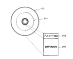
FIG. 1 is a perspective view showing an embodiment of an optical disk according to the present invention. The
本実施の形態の2層型光ディスク101においては、光入射面に対する第1の情報記録層103の位置は、情報記録層を一つしか持たない単層光ディスク(図示せず)の入射面に対する情報記録層の位置と同一とすることが好ましく、例えば、第1の情報記録層103は、光入射面から約100μmの位置に配置される。
In the two-layer
図2は、光ディスク101における第1の情報記録層103の構造を示している。第1の情報記録層103にはトラック201が形成されている。トラック201は、同心円状に複数のトラックが形成されていてもよいし、単一のトラックがスパイラル状に形成されていてもよいし、複数のトラックがスパイラル状に形成されていてもよい。
FIG. 2 shows the structure of the first
第1の情報記録層103は、プリレコード領域202と記録可能領域203とを含んでいる。プリレコード領域202には、第1の情報記録層103にアクセスするために必要とされる各種のパラメータが格納されている。プリレコード領域202は、光ディスクの最内周に配置される。記録可能領域203には、記録学習のための試し記録やユーザデータの記録が行われる。記録可能領域203は、プリレコード領域202の外周に配置される。
The first
なお、図2には第1の情報記録層103の構成を示したが、第2の情報記録層105についてもほぼ同じである。
Although FIG. 2 shows the configuration of the first
図3は、図1に示した光ディスク101の第1の情報記録層103及び第2の情報記録層105に配置される領域の配置構造の一例を示している。
FIG. 3 shows an example of an arrangement structure of regions arranged in the first
第1の情報記録層103のプリレコード領域202aは、光ディスクの識別情報などの情報を記録している領域である。この情報は、基板102又はスペース層104(図1参照。)に形成された、エンボス状のピット、ウォブルグルーブ、もしくはウォブルピット等により記録した領域である。
The
プリレコード領域202aは、バッファとしてのプロテクト領域301aと、コントロールデータ領域302aとを含んでいる。コントロールデータ領域302aは、光ディスクの識別情報として、ディスクタイプ、ディスクサイズ、ディスク構造、チャネルビット、データゾーン配置情報、記録線速度、再生可能最大パワー、記録パワー情報、記録パルス情報及びディスク固有情報のうち少なくとも1つを記録している。本実施の形態においては、コントロールデータ領域302aは、第1の情報記録層に関する情報と第2の情報記録層に関する情報との両方を含んでいる。
The
第2の情報記録層のプリレコード領域202bは、少なくともバッファとしてのプロテクト領域301bを含んでいる。
The
第1の情報記録層の記録可能領域203aは、プリレコード領域202aと記録可能領域203aのトラックピッチが異なる場合にトラックピッチの遷移領域として用いることができる、データを含まないプロテクト領域303aと、第1の記録学習領域304aと、バッファ領域305aと、光ディスク101の様々な特性などの情報を格納するために利用されるドライブ管理情報領域306aと、バッファ領域307aと、ユーザデータ等を記録するユーザデータ記録領域308aと、バッファ領域309aと、将来の拡張のための空き領域であるリザーブ領域310aと、バッファ領域311aと、データを含まないプロテクト領域312aとを含む。
The
第2の情報記録層の記録可能領域203bは、第2の記録学習領域302bと、プロテクト領域303bと、リザーブ領域304bと、バッファ領域305bと、リザーブ領域306bと、バッファ領域307bと、ユーザデータ等を記録するユーザデータ領域308bと、バッファ領域309bと、リザーブ領域310bと、バッファ領域311bと、プロテクト領域312bとを含む。プロテクト領域303b、312bは、データを含まない領域である。リザーブ領域304b、306b、310bは、将来の拡張のための空き領域である。
The
第1の情報記録層に含まれるプロテクト領域303aと第2の情報記録層に含まれるプロテクト領域303bとは、同じ半径位置に配置されている。
The protect
さらに、第2の情報記録層に含まれる第2の記録学習領域302bは、第1の情報記録層のコントロールデータ領域302aと同じ半径位置に配置されるか、あるいはその最外周半径位置がコントロールデータ領域302aの最外周半径位置と等しく配置されている。
Furthermore, the second
第2の情報記録層の記録可能領域203bに含まれるリザーブ領域304b、バッファ領域305b及びリザーブ領域306bは、それぞれ第1の情報記録層の第1の記録学習領域304a、バッファ領域305a及びドライブ管理情報領域306aと同じ半径位置に配置されている。
The reserved
また、第2の情報記録層の記録可能領域203bに含まれるバッファ領域307b、ユーザデータ記録領域308b、バッファ領域309b、リザーブ領域310b、バッファ領域311b及びプロテクト領域312bは、それぞれ第1の情報記録層103のバッファ領域307a、ユーザデータ記録領域308a、バッファ領域309a、リザーブ領域310a、バッファ領域311a及びプロテクト領域312aと同じ半径位置に配置されている。
Also, the
本実施の形態において、光ディスク101を回転させトラックを追従して記録又は再生を行うときの方向は、第1の情報記録層103では内周側から外周側(矢印313a)であり、第2の情報記録層105では外周側から内周側(矢印313b)であり、それぞれ連続的に記録又は再生が行われる。また、本実施の形態においてこの光ディスクにデータを記録又は再生する際は、まず、第1の情報記録層のコントロールデータ領域302aに記録されているコントロールデータの一部もしくは全部を、第2の情報記録層に含まれる第2の記録学習領域302bを介してコントロールデータ領域302aにレーザ光を照射することにより読み出す。
In the present embodiment, the direction in which recording or reproduction is performed by rotating the
図4に、本実施の形態の光ディスクにおいて、第1の情報記録層及び第2の情報記録層に含まれる領域の主要部の半径位置関係を示した領域配置図が示されている。同図において、上部には、第1の情報記録層のプロテクト領域301a、コントロールデータ領域302a、プロテクト領域303a、第1の記録学習領域304a、バッファ領域305a、ドライブ管理情報領域306a、バッファ領域307a及びユーザデータ記録領域308aが示されている。同図において、下部には、第2の情報記録層のプロテクト領域301b、第2の記録学習領域302b、プロテクト領域303b、リザーブ領域304b、バッファ領域305b、リザーブ領域306b、バッファ領域307b及びユーザデータ記録領域308bが示されている。
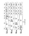
FIG. 4 shows an area layout showing the radial positional relationship of the main parts of the areas included in the first information recording layer and the second information recording layer in the optical disc of the present embodiment. In the figure, at the top, a protected
第2の記録学習領域302bは、第1の情報記録層のコントロールデータ領域302aに対向して配置されている。すなわち、第2の記録学習領域302bは、コントロールデータ領域302aが設けられている半径位置範囲内に配置されている。なお、トラックの偏心や公差が存在する場合に第2の記録学習領域302bの一部がコントロールデータ領域302aから少しはみ出す(プロテクト領域303aと少し重なる)ことも考えられるが、ここでは、このような場合も、第2の記録学習領域302bがコントロールデータ領域302aの半径位置範囲内に配置されているものとする。詳しくは、第2の記録学習領域302bの最外周半径R2がコントロールデータ領域302aの最外周半径R4と同じであり、かつ、第2の記録学習領域302bの最内周半径R3がコントロールデータ領域302aの最内周半径R5と同じ、又は大きい位置となるように配置されている。コントロールデータ領域302aでは、ピットやウォブル形状にレーザ光を照射して反射光量を検出し、そこに記録されているコントロールデータを再生するだけなので、レーザ光が第2の情報記録層を透過する時に、第2の記録学習領域302bの記録状態による強度変化を受けても、コントロールデータの再生信号品質に与える影響はほとんどない。
The second
次に、本実施の形態の光ディスク(図1参照。)の製造方法について、図12A〜図12Fを用いて、以下に簡単に説明する。 Next, a method for manufacturing the optical disc (see FIG. 1) of the present embodiment will be briefly described below with reference to FIGS. 12A to 12F.
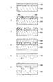
まず、基板102に情報信号を記録するためのトラックやエンボスピットを形成するためのマスタースタンパを作製する。マスタースタンパ形成方法の一例を以下に説明する。まず、スタンパ原盤1001にフォトレジストを塗布してフォトレジスト層1002を形成する(図12A参照。)。このようにフォトレジスト層1002が設けられたスタンパ原盤1001を回転させ、フォトレジスト層1002にレーザ光を照射しながら照射位置を半径方向に所定の速度で移動させることにより、フォトレジスト層1002に対し、スパイラル状のトラックが形成される部分が露光される(図12B参照。)。図12において、1003はフォトレジスト層1002の露光部を示している。このとき、レーザ光の光路上に光偏向器(図示せず。)を設け、入力される信号(例えばアドレス情報に対応する信号)に応じてレーザ光を半径方向に微小に振動させることにより、トラックをウォブルさせることができる。このようにすれば、アドレス情報をトラックのウォブルとしてディスク全面に渡って記録させておくことができる。さらに、アドレス情報だけでなく、前述のコントロールデータ領域に対応する半径位置に、コントロールデータに応じてウォブルしたトラックを形成することもできる。このように、所定の位置にコントロールデータを形成することにより、所定の半径位置にコントロールデータ領域を形成できる。露光後、現像やエッチングを経ることにより、凹凸形状を露出させる(図12C参照。)。次に、この凹凸形状を転写することにより(図12D参照。)マスタースタンパ1004を形成する(図12E参照。)。本実施の形態の光ディスクは、いわゆるイングルーブ記録を採用しているので、マスタースタンパ1004からさらに転写によりマザースタンパ1005を作製する(図12F参照。)。
First, a master stamper for forming tracks and emboss pits for recording information signals on the
以上のように形成されたマザースタンパ1005を用い、ポリカーボネートやポリメチルメタクリレート(PMMA)等の材料を用いてインジェクション成形等によって、表面にアドレス信号やコントロールデータに応じたトラックが設けられた基板102を形成する。このように基板102を形成することにより、後の工程において、基板102上に形成される第1の情報記録層103の各領域を図4に示すように配置できる。なお、以上に説明した方法ではコントロールデータ領域をウォブルで形成したが、エンボスピットにより形成することもできる。この場合は、光偏向器ではなく、光強度変調器をレーザ光光路上に設置し、入力される信号(ここではコントロールデータに対応した信号)に応じてレーザ光の強度を変調することにより、フォトレジスト層にピット状の露光部を形成できる。この場合も現像から後の処理はウォブルの場合と同様である。
Using the mother stamper 1005 formed as described above, a
その後、基板102上に、複数の光学薄膜からなる第1の情報記録層103をスパッタリング法により形成する。複数の光学薄膜とは、例えば、金属反射膜、誘電体保護層、界面層、記録層、界面層及び誘電体保護層がこの順で基板上に形成された多層膜である。なお、多層膜のうち、界面層や誘電体保護層は一部を省略することも可能である。また、記録層は、例えば、Ge、Te及びSbを含む書き換え型相変化材料や、Te、Pd及びO等を含む追記型相変化材料や、Cu及びSiを含む追記型金属材料等が用いられる。また、光学薄膜として色素系記録層を設けることも可能であり、このときはスパッタリング法だけでなくスピンコート法を用いることもできる。
Thereafter, a first
このように基板102上に多層膜が形成された後、樹脂からなるスペース層104を形成する。別途作製したマスタースタンパ(基板102の作製に用いたマスタースタンパとは別のスタンパである。なお、このマスタースタンパを形成する方法も、前述のマスタースタンパ作製方法と類似である。)を用い、フォトポリマー(2P)法や、シート状の両面テープにそのマスタースタンパをプレスする方法等により、スペース層104の第2の情報記録層が形成される側の表面にも、情報信号を記録するためのトラックやエンボスピットを形成する。このようにスペース層104を形成することにより、後の工程において、スペース層104上に形成される第2の情報記録層105の各領域を図4に示すように配置できる。
After the multilayer film is formed on the
スペース層104が形成された後は、第2の情報記録層105が第1の情報記録層103と同様の方法で形成されるが、第2の情報記録層105は記録再生用のレーザ光の一部を透過させるため、第1の情報記録層103の光学薄膜とは異なる構成を有する。例えば、金属反射層を薄く形成する、もしくは省略する構成や、金属反射層とスペース層104との間に高屈折率誘電体層を設けて透過率を高くする構成が考えられる。
After the formation of the space layer 104, the second
第2の情報記録層105を形成した後、光透過層106が形成される。光透過層106は、例えば、光硬化性樹脂を塗布しスピンコート法により形成する方法や、樹脂シートを貼り合わせる方法等を用いて形成できる。
After forming the second
以上のように、アドレス信号やコントロールデータに対応するトラックやエンボスピットの形状が設けられたマスタースタンパを用いて基板102及びスペース層104を形成することにより、各領域が前述の位置関係ように(図4に示すように)配置された光ディスク101を作製できる。
As described above, by forming the
本実施の形態の光ディスクでは、図4に示すように、第2の記録学習領域302bと重なる半径位置にコントロールデータ領域302aを配置したことにより、第1の情報記録層における第2の記録学習領域302bと対向する領域にリザーブ領域を追加する必要がない。一般に、情報記録層が一層設けられた単層光ディスクの場合、情報記録層の手前(情報記録層よりもレーザ光入射側)に他の情報記録層(本実施の形態の光ディスクの第2の情報記録層に相当する層)が存在しないため、手前の情報記録層における記録学習領域による影響を避けるためのリザーブ領域は存在しない。本実施の形態の光ディスクは、第1の情報記録層をこのような単層光ディスクと同じ領域構成にすることができる。例えば、ユーザデータ記録領域308a及び308bの最内周半径R0を単層光ディスクの場合と同一にできるので、ユーザデータの記録容量が減縮されない。このように、ユーザデータ領域308a,308bの半径とアドレスが単層光ディスクの場合と変わらないので、光ディスク記録再生装置を用いて本実施の形態の光ディスクにデータを記録又は再生する場合のアクセスも容易になる。このため、ユーザデータ等の記録容量の減縮を避けることができる。
In the optical disc of the present embodiment, as shown in FIG. 4, the
また、コントロールデータ領域302aと第1の記録学習領域304aとの間にはプロテクト領域303aが配置されている。プロテクト領域303aは、第1の記録学習領域304aの最内周半径R1と第2の記録学習領域302bの最外周半径R2との差に相当する幅を有している。本実施の形態において、プロテクト領域303aの幅(R1−R2)は、第1及び第2の情報記録層のトラックの偏心量の最大値(Δe)と、第1の情報記録層にレーザ光が収束されているときの第2の情報記録層におけるレーザ光のビーム径(D)と、トラック始端の半径位置の公差(Δr)とを考慮して設定される。これにより、トラックの偏心や公差が存在した場合でも、第1の記録学習領域304aと第2の記録学習領域302bとが重ならないようにできるので、記録学習を適切に行うことができる。一般に、トラックの偏心や公差は2つの情報記録層の間(第1の情報記録層と第2の情報記録層との間)で逆方向になる場合があるので、最悪の場合を想定し、R1−R2≧2×(Δe+Δr)+Dに設定することが好ましい。これにより、プロテクト領域303aの幅が十分となり、記録学習をより適切に行えるからである。
A
また、第2の情報記録層においては、第1の記録学習領域304aと同じ半径位置にデータの記録されないリザーブ領域304bが配置されているので、常に一定の状態(未記録状態、もしくは将来何かの情報がリザーブ領域304bに記録された場合は最適記録パワーで記録された状態)の第2の情報記録層を通して安定な記録学習ができる。
In the second information recording layer, a
さらに、本実施の形態においては、第1の情報記録層のコントロールデータ領域302aには、第1の情報記録層と第2の情報記録層との両方の記録パルス等のメディア固有情報が格納されている。これにより、まず第1の情報記録層にアクセスすることで全ての識別情報が得られるため、光ディスクドライブのスタートアップ動作が早くなるという利点がある。
Further, in the present embodiment, media-specific information such as recording pulses of both the first information recording layer and the second information recording layer is stored in the
また、本実施の形態の2層型光ディスクにユーザデータを記録再生することが可能な光ディスク記録再生装置は、単層光ディスクに対してもユーザデータを記録再生できるのが一般的である。上述したように、本実施の形態の2層型光ディスクにおいては、光入射面に対する第1の情報記録層の位置を、情報記録層を一つしか持たない単層光ディスクの入射面に対する情報記録層の位置と同一にしている。すなわち、本実施の形態の2層型光ディスクは、単層光ディスクの情報記録層と光入射面に対して同じ位置にある第1の情報記録層にコントロールデータ領域302aを配置している。従って、本実施の形態の2層型光ディスクを光ディスク記録再生装置にロードしたときに、単層光ディスクと光学的に同じ条件でレーザ光をコントロールデータ領域302aに照射できる。これにより、識別情報の読みとりがスムーズになるという効果が得られる。
Also, the optical disc recording / reproducing apparatus capable of recording / reproducing user data on the two-layer type optical disc of the present embodiment is generally capable of recording / reproducing user data on a single-layer optical disc. As described above, in the two-layer type optical disc of the present embodiment, the position of the first information recording layer with respect to the light incident surface is the information recording layer with respect to the incident surface of the single-layer optical disc having only one information recording layer. The position is the same. That is, in the two-layer type optical disc of the present embodiment, the
なお、図3の矢印313a及び313bで示したように記録再生の方向を定め、第1の情報記録層では内周側から外周側へ連続してユーザデータを記録し、第1の情報記録層のユーザデータ記録領域308aが一杯になれば、第2の情報記録層の外周側から内周側へ向かってユーザデータを記録するようにしても良い。この場合、第1の情報記録層にユーザデータを記録する際には、レーザ光が透過する第2の情報記録層は全て未記録状態なので、最適記録パワーであっても第2の情報記録層の記録によって透過光が影響を受けるような記録材料を用いることができ、第2の情報記録層の材料の選択範囲が広がる。このような記録材料を用いても、本構成によれば、第1の記録学習領域304aと第2の記録学習領域302bとは重なることがないため、記録学習が適切に行われることはいうまでもない。特に、1回記録のみ可能なWrite−once型(追記型)の光ディスクにおいては、上述したように内周側から外周側もしくは外周側から内周側へと連続に記録することが一般的であるので、本構成を適用する効果が大きい。
As shown by
(実施の形態2)
本発明の光ディスクの別の一実施形態について以下に説明する。本実施の形態の光ディスクは、2層の情報記録層を備えており、各情報記録層に配置される領域の構造が異なる以外は、実施の形態1の光ディスクと同じである。従って、本実施の形態の光ディスクによれば、実施の形態1の光ディスクと同様の効果が得られる。
(Embodiment 2)
Another embodiment of the optical disk of the present invention will be described below. The optical disc according to the present embodiment includes two information recording layers, and is the same as the optical disc according to the first embodiment, except that the structure of the region arranged in each information recording layer is different. Therefore, according to the optical disk of the present embodiment, the same effect as the optical disk of the first embodiment can be obtained.
図5に、本実施の形態の光ディスクの第1の情報記録層及び第2の情報記録層に含まれる領域の主要部の半径位置関係を示した領域配置図が示されている。同図において、上部には、第1の情報記録層のプロテクト領域301a、コントロールデータ領域302a、プロテクト領域303a、第1の記録学習領域304a、バッファ領域305a、ドライブ管理情報領域306a、バッファ領域307a及びユーザデータ記録領域308aが示されている。同図において、下部には、第2の情報記録層のプロテクト領域301b、第2の記録学習領域302b、リザーブ領域501b、プロテクト領域303b、リザーブ領域304b、バッファ領域305b、リザーブ領域306b、バッファ領域307b及びユーザデータ記録領域308bが示されている。なお、実施の形態1の光ディスクの各領域と実質的に同一である領域には実施の形態1の場合と同様の参照番号(図4参照。)を付し、詳細な説明は省略する。
FIG. 5 shows an area arrangement diagram showing a radial positional relationship of main parts of areas included in the first information recording layer and the second information recording layer of the optical disc of the present embodiment. In the figure, at the top, a protected
本実施の形態の光ディスクにおいて、第2の記録学習領域302bは、コントロールデータ領域302aに対向する領域に配置されている。すなわち、第2の記録学習領域302bは、コントロールデータ領域302aが設けられている半径位置範囲内に配置されている。なお、トラックの偏心や公差が存在する場合に第2の記録学習領域302bの一部がコントロールデータ領域302aから少しはみ出す(プロテクト領域301aと少し重なる)ことも考えられるが、ここでは、このような場合も、第2の記録学習領域302bがコントロールデータ領域302aの半径位置範囲内に配置されているものとする。詳しくは、第2の記録学習領域302bその最内周半径R3がコントロールデータ領域302aの最内周半径R5と同じ、又は大きく、かつ、第2の記録学習領域302bの最外周半径R2がコントロールデータ領域302aの最外周半径R4より小さくなるように配置されている。実施の形態1において説明したように、レーザ光が第2の情報記録層を透過する時に、第2の記録学習領域302bの記録状態による強度変化を受けても、コントロールデータの再生信号品質に与える影響はほとんどない。さらに、第2の記録学習領域302bと重なる半径位置にコントロールデータ領域302aを配置したことにより、実施の形態1の場合と同様に、第1の情報記録層において第2の記録学習領域302bに対向する領域にリザーブ領域を追加する必要がなく、第1の情報記録層を単層光ディスクと同じ領域構成にすることが可能となる。例えば、ユーザデータ記録領域308a及び308bの最内周半径R0を単層光ディスクの場合と同一にできるので、ユーザデータの記録容量が減縮されない。このように、ユーザデータ領域308a,308bの半径とアドレスが単層光ディスクの場合と変わらないので、光ディスク記録再生装置を用いて本実施の形態の光ディスクに情報を記録再生する場合のアクセスも容易になる。このため、ユーザデータ等の記録容量の減縮を避けることができる。
In the optical disk of the present embodiment, the second
また、第2の記録学習領域302bの外隣にはリザーブ領域501bが配置されており、このリザーブ領域501bとプロテクト領域303bとを合わせた幅が、第1の記録学習領域304aの最内周半径R1と第2の記録学習領域302bの最外周半径R2との差に相当する。本実施の形態において、リザーブ領域501bとプロテクト領域303bとを合わせた幅(R1−R2)は、第1及び第2の情報記録層のトラックの偏心量の最大値(Δe)と、第1の情報記録層にレーザ光が収束されているときの第2の情報記録層におけるレーザ光のビーム径(D)と、トラック始端の半径位置の公差(Δr)とを考慮して設定される。これにより、トラックの偏心や公差が存在した場合でも、第1の記録学習領域304aと第2の記録学習領域302bとが重ならないようにできるので、記録学習を適切に行うことができる。本実施の形態においては、プロテクト領域303bだけでなく、リザーブ領域501bも使って、第1の情報記録学習領域と第2の情報記録学習領域との間に所望の間隙を設けることができる。従って、リザーブ領域501bの分だけ第1の情報記録層のプロテクト領域303a及び第2の情報記録層のプロテクト領域303bの幅を小さくできるので、ユーザデータなどの記録容量の減縮をさらに抑制できる。
Further, a
以上の実施の形態1及び2で説明した光ディスクでは、プリレコード領域、特にコントロールデータ領域での識別情報の再生を安定させるため、トラックピッチを記録可能領域に比べて広くしても良い。この場合、第2の情報記録層においては、プリレコード領域はプロテクト領域301bだけなので、プロテクト領域301bのトラックピッチを記録可能領域と同一にしてもよい。
In the optical disks described in the first and second embodiments, the track pitch may be wider than the recordable area in order to stabilize the reproduction of the identification information in the prerecord area, particularly the control data area. In this case, in the second information recording layer, since the pre-record area is only the protected
(実施の形態3)
図6は、本発明の光ディスクのさらに別の一実施形態を示す斜視図である。本実施の形態の光ディスク401は、情報記録層が4層設けられており、一方の面から入射されたレーザ光により各情報記録層に対してデータの記録及び再生が行われる片面4層型光ディスクである。
(Embodiment 3)
FIG. 6 is a perspective view showing still another embodiment of the optical disc of the present invention. The
本実施の形態の光ディスク401において、402は基板、403は第1の情報記録層、404は第1のスペース層、405は第2の情報記録層、406は第2のスペース層、407は第3の情報記録層、408は第3のスペース層、409は第4の情報記録層、4
10は光透過層である。第1〜第3のスペース層404,406,408は、接着樹脂等にて形成されている。光透過層410側からレーザ光を照射し、第1の情報記録層403、第2の情報記録層405、第3の情報記録層407及び第4の情報記録層409にデータを記録又は再生する。
In the
Reference numeral 10 denotes a light transmission layer. The first to third space layers 404, 406, and 408 are formed of an adhesive resin or the like. Laser light is irradiated from the
本実施の形態の4層型光ディスク401においては、光入射面に対する第1の情報記録層403の位置を、情報記録層を一つしか持たない単層光ディスク(図示せず)の入射面に対する情報記録層の位置と同一とすることが好ましい。そこで、本実施の形態における各層の厚さは、例えば、光透過層410は約40〜60μm、第1のスペース層404、第2のスペース層406及び第3のスペース層408は約15〜20μm、基板402は約1.1mmとし、第1の情報記録層403、第2の情報記録層405、第3の情報記録層407及び第4の情報記録層409はいずれも数10nm〜数100nmとする。
In the four-layer type
図7に、本実施の形態における光ディスクに配置される領域の主要部の半径位置関係を示した配置図を示す。同図においては、最上段に第1の情報記録層、次の段に第2の情報記録層、さらに次の段に第3の情報記録層、最下段に第4の情報記録層を示し、各情報記録層における領域の配置を示している。第1の情報記録層には、ディスク内周側から順に、プロテクト領域701a、コントロールデータ領域702a、プロテクト領域703a、第1の記録学習領域704a、バッファ領域705a、ドライブ管理情報領域706a、バッファ領域707a、ユーザデータ記録領域708aが配置されている。第2の情報記録層には、ディスク内周側から順に、プロテクト領域701b、第2の記録学習領域702b、プロテクト領域703b、リザーブ領域704b、バッファ領域705b、リザーブ領域706b、バッファ領域707b、ユーザデータ記録領域708bが配置されている。第3の情報記録層には、ディスク内周側から順に、プロテクト領域701c、第3の記録学習領域702c、プロテクト領域703c、リザーブ領域704c、バッファ領域705c、リザーブ領域706c、バッファ領域707c、ユーザデータ記録領域708cが配置されている。最後に、第4の情報記録層には、ディスク内周側から順に、プロテクト領域701d、第4の記録学習領域702d、プロテクト領域703d、リザーブ領域704d、バッファ領域705d、リザーブ領域706d、バッファ領域707d、ユーザデータ記録領域708dが配置されている。
FIG. 7 is a layout diagram showing the radial positional relationship of the main part of the region arranged on the optical disc in the present embodiment. In the figure, the first information recording layer is shown at the top, the second information recording layer at the next, the third information recording layer at the next, the fourth information recording layer at the bottom, The arrangement of areas in each information recording layer is shown. In the first information recording layer, a
本実施の形態の光ディスクにおいては、第2の記録学習領域702b、第3の記録学習領域702c及び第4の記録学習領域702d全てが、第1の情報記録層のコントロールデータ領域702aが設けられている半径位置範囲内に配置されており、コントロールデータ領域702aと重なっている。すなわち、本実施の形態においては、第2〜第4の情報記録層全てが、上記に説明した第iの情報記録層に該当する。このような配置にしたことにより、実施の形態1及び2で説明した2層型光ディスクと同様に、第2、第3及び第4の記録学習領域702b,702c,702dの記録状態によってこれらの層の透過率が変化することがあっても、第1の情報記録層の記録学習に影響を与えることはない。従って、実施の形態1及び2で説明した2層型光ディスク同様、第1の情報記録層に対して精度の良い記録学習が可能となる。
In the optical disc of the present embodiment, the second
さらに、本実施の形態では、第2の記録学習領域702b、第3の記録学習領域702c及び第4の記録学習領域702dが互いに異なる半径位置に配置されているので、第3及び第4の記録学習領域702c,702dの記録状態によってこれらの層の透過率が変化することがあっても第2の情報記録層の記録学習に影響を与えることがなく、第4の記録学習領域702dの記録状態によってこの層の透過率が変化することがあっても第3の情報記録層の記録学習に影響を与えることはない。これにより、第2及び第3の情報記録層に対しても精度の良い記録学習が可能となる。
Furthermore, in the present embodiment, the second
また、第3の記録学習領域702c及び第4の記録学習領域702dは、第2の情報記録層におけるプロテクト領域701bが設けられている半径位置範囲内に配置されており、プロテクト領域701bと重なっている。さらに、第4の記録学習領域702dは、第2の情報記録層のプロテクト領域701b及び第3の情報記録層のプロテクト領域701cが設けられている半径位置範囲内に配置されており、プロテクト領域701b,701cと重なっている。すなわち、本実施の形態においては、第3及び第4の情報記録層が、上記に説明した第jの情報記録層に該当する。これにより、各情報記録層の記録学習領域と重なるように、その情報記録層よりもレーザ光入射側からみて奥に配置された情報記録層にリザーブ領域等の空き領域を追加する必要がなくなるため、各情報記録層における記録容量を減縮することなく、4層の情報記録層を有する光ディスクを実現できる。
Further, the third
なお、本実施の形態の光ディスクでも、互いに隣接する二つの情報記録層において、より奥側の情報記録層(上記に説明した第kの情報記録層に該当)の記録学習領域における最内周の半径(R1)と、より手前側の情報記録層(上記に説明した第k+1の情報記録層に該当)の記録学習領域における最外周の半径(R2)との差(R1−R2)は、実施の形態1の光ディスクの場合と同様に、トラック偏心量の最大値、レーザ光のビーム径及びトラック始端の半径位置の公差を考慮して設定されることが好ましい。また、本実施の形態の光ディスクを用いてデータの記録又は再生を行う場合も、実施の形態1の光ディスクの場合と同様、まず、第1の情報記録層のコントロールデータ領域に記録されているコントロールデータの一部もしくは全部を、第2〜第4の情報記録層に含まれる記録学習領域の少なくとも一つを介してコントロールデータ領域にレーザ光を照射することにより読み出し、データの記録又は再生を行う。 Even in the optical disc of the present embodiment, the innermost circumference in the recording learning area of the deeper information recording layer (corresponding to the k-th information recording layer described above) in the two adjacent information recording layers. The difference (R1−R2) between the radius (R1) and the outermost radius (R2) in the recording learning area of the information recording layer on the nearer side (corresponding to the k + 1th information recording layer described above) is As in the case of the optical disc of the first embodiment, it is preferable to set in consideration of the tolerance of the maximum value of the track eccentricity, the beam diameter of the laser beam, and the radial position of the track start end. Also, when data is recorded or reproduced using the optical disk of the present embodiment, the control recorded in the control data area of the first information recording layer is the same as in the case of the optical disk of the first embodiment. A part or all of the data is read out by irradiating the control data area with laser light via at least one of the recording learning areas included in the second to fourth information recording layers, and data is recorded or reproduced. .
(実施の形態4)
本発明の光ディスクのさらに別の一実施形態について以下に説明する。本実施の形態の光ディスクは、各情報記録層に配置される領域の配置が異なる以外は、実施の形態3の光ディスクと同じである。従って、本実施の形態の光ディスクによれば、実施の形態3の光ディスクと同様の効果が得られる。
(Embodiment 4)
Another embodiment of the optical disk of the present invention will be described below. The optical disc of the present embodiment is the same as the optical disc of the third embodiment, except that the arrangement of the areas arranged in each information recording layer is different. Therefore, according to the optical disk of the present embodiment, the same effect as that of the optical disk of the third embodiment can be obtained.
図8に、本実施の形態における光ディスクの領域の主要部の半径位置関係を示した配置図を示す。第1の情報記録層には、ディスク内周側から順に、プロテクト領域701a、コントロールデータ領域702a、プロテクト領域703a、第1の記録学習領域704a、バッファ領域705a、ドライブ管理情報領域706a、バッファ領域707a、ユーザデータ記録領域708aが配置されている。第2の情報記録層には、ディスク内周側から順に、プロテクト領域701b、第2の記録学習領域702b、リザーブ領域804b、バッファ領域705b、リザーブ領域706b、バッファ領域707b、ユーザデータ記録領域708bが配置されている。第3の情報記録層には、ディスク内周側から順に、プロテクト領域701c、第3の記録学習領域702c、リザーブ領域804c、バッファ領域705c、リザーブ領域706c、バッファ領域707c、ユーザデータ記録領域708cが配置されている。最後に、第4の情報記録層には、ディスク内周側から順に、プロテクト領域701d、第4の記録学習領域702d、リザーブ領域804d、バッファ領域705d、リザーブ領域706d、バッファ領域707d、ユーザデータ記録領域708dが配置されている。なお、実施の形態3で説明した光ディスクの各領域と実質的に同一である領域には実施の形態3と同様の参照番号を付している。
FIG. 8 is a layout diagram showing the radial positional relationship of the main part of the area of the optical disk in the present embodiment. In the first information recording layer, a
同図の第2の情報記録層においては、実施の形態3の光ディスクにおけるプロテクト領域703bとリザーブ領域704bが新たにリザーブ領域804bに置き換わっている。同様に、第3の情報記録層においては、実施の形態3の光ディスクにおけるプロテクト領域703cとリザーブ領域704cが新たにリザーブ領域804cに、また、第4の情報記録層においては、実施の形態3の光ディスクにおけるプロテクト領域703dとリザーブ領域704dとが新たにリザーブ領域804dに、置き換わっている。これらリザーブ領域804b、804c及び804dは、その領域が含まれる情報記録層より手前側にある情報記録層の記録学習領域と重ならないので、欠陥が存在するアドレスなどの管理情報を新たに記録できる。これにより、ディスク上の領域を有効に活用できる。
In the second information recording layer shown in the figure, the protected
(実施の形態5)
図9は、本発明の光ディスクのさらに別の一実施形態を示す斜視図である。本実施の形態の光ディスク601は、情報記録層が4層設けられており、一方の面から入射されたレーザ光により各情報記録層に対してデータの記録及び再生が行われる片面4層型光ディスクである。
(Embodiment 5)
FIG. 9 is a perspective view showing still another embodiment of the optical disc of the present invention. The
本実施の形態の光ディスク601において、602は基板、604は第1のスペース層、605は第1の情報記録層、606は第2のスペース層、607は第2の情報記録層、608は第3のスペース層、609は第3の情報記録層、610は光透過層である。第1〜第3のスペース層604,606,608は、接着樹脂等にて形成されている。光透過層610側からレーザ光を照射し、第1の情報記録層605、第2の情報記録層607及び第3の情報記録層609にデータを記録又は再生する。さらに、本実施の形態の光ディスク601には、基準とする第1の情報記録層605に対してレーザ光入射側と反対側に配置された情報記録層603が設けられている。なお、便宜上、以下この情報記録層を第0の情報記録層をいう。第0の情報記録層603に関しても、他の情報記録層と同様、光透過層610側からレーザ光を照射してデータを記録又は再生する。
In the
本実施の形態の4層型光ディスクにおいては、光入射面に対する第1の情報記録層605の位置を、情報記録層を一つしか持たない単層光ディスク(図示せず)の入射面に対する情報記録層の位置と同一とすることが好ましい。そこで、本実施の形態における各層の厚さは、例えば、光透過層610は約50〜70μm、第1のスペース層604、第2のスペース層606及び第3のスペース層608は約15〜25μm、基板602は約1.1mmとし、第1の情報記録層605、第2の情報記録層607、第3の情報記録層609及び第0の情報記録層603はいずれも数10nm〜数100nmとする。基準面をレーザ光入射側から3番目に配置される情報記録層としたことにより、レーザ光入射側に情報記録層が残り2つになるので、実施の形態3で説明した光ディスクの場合よりも、光透過層610と第1〜第3のスペース層604,606,608とを厚く形成できる。これにより、各情報記録層間の光学的なクロストークを低減できる。
In the four-layer type optical disc of the present embodiment, the position of the first
図10に、本実施の形態における光ディスクの領域の主要部の半径位置関係を示した配置図を示す。同図においては、最上段に第0の情報記録層、次の段に第1の情報記録層、次の段は第2の情報記録層、最下段に第3の情報記録層における領域の配置が示されている。第1の情報記録層には、ディスク内周側から順に、プロテクト領域901a、コントロールデータ領域902a、プロテクト領域903a、第1の記録学習領域904a、バッファ領域905a、ドライブ管理情報領域906a、バッファ領域907a、ユーザデータ記録領域908aが配置されている。第2の情報記録層には、ディスク内周側から順に、プロテクト領域901b、第2の記録学習領域902b、プロテクト領域903b、リザーブ領域904b、バッファ領域905b、リザーブ領域906b、バッファ領域907b、ユーザデータ記録領域908bが配置されている。さらに、第3の情報記録層には、ディスク内周側から順に、プロテクト領域901c、第3の記録学習領域902c、プロテクト領域903c、リザーブ領域904c、バッファ領域905c、リザーブ領域906c、バッファ領域907c、ユーザデータ記録領域908cが示されている。最後に、第0の情報記録層は、ディスク内周側から順に、プロテクト領域901d、コントロールデータ領域902d、プロテクト領域903d、バッファ領域905d、第4の記録学習領域906d、バッファ領域907d、ユーザデータ記録領域908dが配置されている。
FIG. 10 is a layout diagram showing the radial positional relationship of the main part of the area of the optical disk in the present embodiment. In the figure, the arrangement of areas in the 0th information recording layer at the top, the first information recording layer at the next, the second information recording at the next, and the third information recording at the bottom. It is shown. In the first information recording layer, a
本実施の形態の光ディスクにおいては、第2の記録学習領域902b及び第3の記録学習領域902cが第1の情報記録層のコントロールデータ領域902a及び第0の情報記録層のコントロールデータ領域902dと重なっている。すなわち、本実施の形態においては、第2及び第3の情報記録層が、上記に説明した第iの情報記録層に該当する。
In the optical disc of the present embodiment, the second
また、第0の情報記録層において、第1の記録学習領域904aと重なる場所にはプロテクト領域903dが配置されている。さらに、第3の記録学習領域902cは、第2の情報記録層のプロテクト領域901bと重なるように配置されている。すなわち、本実施の形態においては、第3の情報記録層が、上記に説明した第jの情報記録層に該当する。このような配置にしたことにより、実施の形態3及び4で説明した4層型光ディスクと同様に、第1、第2及び第3の記録学習領域の記録状態によってこれらの層の透過率が変化することがあっても第0の情報記録層に影響を与えることはなく、第2及び第3の記録学習領域の記録状態によってこれらの層の透過率が変化することがあっても第1の情報記録層に影響を与えることはない。さらに、第0の情報記録層にもコントロールデータ領域を備えたことにより、コントロールデータを備えた領域が2カ所になるので、コントロールデータ読み出しを失敗する可能性が減り、本実施の形態における光ディスクを用いた装置の使い勝手が良くなる。
In the 0th information recording layer, a
なお、本実施の形態の光ディスクでも、互いに隣接する二つの情報記録層において、より奥側の情報記録層(上記に説明した第kの情報記録層に該当)の記録学習領域における最内周の半径(R1)と、より手前側の情報記録層(上記に説明した第k+1の情報記録層に該当)の記録学習領域における最外周の半径(R2)との差(R1−R2)は、実施の形態1の光ディスクの場合と同様に、トラック偏心量の最大値、レーザ光のビーム径及びトラック始端の半径位置の公差を考慮して設定されることが好ましい。また、本実施の形態の光ディスクを用いてデータの記録又は再生を行う場合も、実施の形態1の光ディスクの場合と同様、まず、第1の情報記録層又は第0の情報記録層のコントロールデータ領域に記録されているコントロールデータの一部又は全部を、第2又は第3の情報記録層に含まれる記録学習領域を介してコントロールデータ領域にレーザ光を照射することにより読み出し、データの記録又は再生を行う。 Even in the optical disc of the present embodiment, the innermost circumference in the recording learning area of the deeper information recording layer (corresponding to the k-th information recording layer described above) in the two adjacent information recording layers. The difference (R1−R2) between the radius (R1) and the outermost radius (R2) in the recording learning area of the information recording layer on the nearer side (corresponding to the k + 1th information recording layer described above) is As in the case of the optical disc of the first embodiment, it is preferable to set in consideration of the tolerance of the maximum value of the track eccentricity, the beam diameter of the laser beam, and the radial position of the track start end. Also, when data is recorded or reproduced using the optical disc of the present embodiment, first, the control data of the first information recording layer or the 0th information recording layer is the same as in the case of the optical disc of the first embodiment. A part or all of the control data recorded in the area is read out by irradiating the control data area with laser light through the recording learning area included in the second or third information recording layer, Perform playback.
(実施の形態6)
本発明の光ディスクのさらに別の一実施形態について以下に説明する。本実施の形態の光ディスクは、各情報記録層に配置される領域の配置が異なる以外は、実施の形態5の光ディスクと同じである。従って、本実施の形態の光ディスクによれば、実施の形態5の光ディスクと同様の効果が得られる。
(Embodiment 6)
Another embodiment of the optical disk of the present invention will be described below. The optical disc of the present embodiment is the same as the optical disc of the fifth embodiment, except that the arrangement of the areas arranged in each information recording layer is different. Therefore, according to the optical disc of the present embodiment, the same effect as the optical disc of the fifth embodiment can be obtained.
図11に、本実施の形態における光ディスクの領域の主要部の半径位置関係を示した配置図を示す。第1の情報記録層には、ディスク内周側から順に、プロテクト領域901a、コントロールデータ領域902a、プロテクト領域903a、第1の記録学習領域904a、バッファ領域905a、ドライブ管理情報領域906a、バッファ領域907a、ユーザデータ記録領域908aが配置されている。第2の情報記録層には、ディスク内周側から順に、プロテクト領域901b、第2の記録学習領域902b、リザーブ領域914b、バッファ領域905b、リザーブ領域906b、バッファ領域907b、ユーザデータ記録領域908bが配置されている。第3の情報記録層には、ディスク内周側から順に、プロテクト領域901c、第3の記録学習領域902c、リザーブ領域914c、バッファ領域905c、リザーブ領域906c、バッファ領域907c、ユーザデータ記録領域908cが配置されている。最後に、第0の情報記録層には、プロテクト領域901d、コントロールデータ領域902d、プロテクト領域903d、バッファ領域905d、第4の記録学習領域906d、バッファ領域907d、ユーザデータ記録領域908dが配置されている。なお、実施の形態5の光ディスクの各領域と実質的に同一である領域には実施の形態5と同様の参照番号を付している。
FIG. 11 is a layout diagram showing the radial positional relationship of the main part of the area of the optical disk in the present embodiment. In the first information recording layer, a
同図の第2の情報記録層においては、実施の形態5のプロテクト領域903bとリザーブ領域904bが新たにリザーブ領域914bに置き換わっている。同様に、第3の情報記録層においては、実施の形態5のプロテクト領域903cとリザーブ領域904cが新たにリザーブ領域914cに置き換わっている。これらリザーブ領域914b,914cでは、その領域が含まれる情報記録層よりレーザ光入射側にある情報記録層に含まれる記録学習領域と重なることはないので、欠陥が存在するアドレスなどの管理情報を新たに記録できる。これにより、ディスク上の領域を有効に活用できる。
In the second information recording layer shown in the figure, the protected
本発明の光ディスク及びその製造方法は、複数設けられた情報記録層それぞれに対して精度の良い記録学習が要求される光ディスクの提供に有用である。また、本発明のデータの記録方法及び再生方法は、情報記録層毎に適切な条件でデータを記録又は再生することが要求される場合のデータの記録又は再生に適用できる。 INDUSTRIAL APPLICABILITY The optical disc and the manufacturing method thereof of the present invention are useful for providing an optical disc that requires accurate recording learning for each of a plurality of information recording layers. The data recording method and reproducing method of the present invention can be applied to data recording or reproducing when it is required to record or reproduce data under appropriate conditions for each information recording layer.
101 光ディスク
102 基板
103 第1の情報記録層
104 スペース層
105 第2の情報記録層
106 光透過層
201 トラック
202 プリレコード領域
203 記録可能領域
301a,301b プロテクト領域
302a コントロールデータ領域
302b 第2の記録学習領域
303a,303b プロテクト領域
304a 第1の記録学習領域
304b リザーブ領域
305a,305b バッファ領域
306a ドライブ管理情報領域
306b リザーブ領域
307a,307b バッファ領域
308a,308b ユーザデータ領域
309a,309b バッファ領域
310a,310b リザーブ領域
311a,311b バッファ領域
312a,312b プロテクト領域
313a,313b 記録再生方向
501b リザーブ領域
401 光ディスク
402 基板
403 第1の情報記録層
404,406,408 スペース層
405 第2の情報記録層
407 第3の情報記録層
409 第4の情報記録層
410 光透過層
701a,701b,701c,701d プロテクト領域
702a コントロールデータ領域
702b 第2の記録学習領域
702c 第3の記録学習領域
702d 第4の記録学習領域
703a,703b,703c,703d プロテクト領域
704a 第1の記録学習領域
704b,704c,704d リザーブ領域
705a,705b,705c,705d バッファ領域
706a ドライブ管理情報領域
706b,706c,706d リザーブ領域
707a,707b,707c,707d バッファ領域
708a,708b,708c,708d ユーザデータ領域
804b,804c,804d リザーブ領域
601 光ディスク
602 基板
603 第0の情報記録層
604,606,608 スペース層
605 第1の情報記録層
607 第2の情報記録層
609 第3の情報記録層
610 光透過層
901a,901b,901c,901d プロテクト領域
902a,902d コントロールデータ領域
902b 第2の記録学習領域
902c 第3の記録学習領域
903a,903b,903c,903d プロテクト領域
904a 第1の記録学習領域
904b,904c リザーブ領域
905a,905b,905c,905d バッファ領域
906a ドライブ管理情報領域
906b,906c リザーブ領域
906d 第0の記録学習領域
907a,907b,907c,907d バッファ領域
908a,908b,908c,908d ユーザデータ領域
914b,914c リザーブ領域
1001 スタンパ原盤
1002 フォトレジスト層
1003 露光部
1004 マスタースタンパ
1005 マザースタンパ
101 optical disc 102 substrate 103 first information recording layer 104 space layer 105 second information recording layer 106 light transmission layer 201 track 202 prerecord area 203 recordable area 301a, 301b protect area 302a control data area 302b second recording learning Area 303a, 303b Protect area 304a First recording learning area 304b Reserve area 305a, 305b Buffer area 306a Drive management information area 306b Reserve area 307a, 307b Buffer area 308a, 308b User data area 309a, 309b Buffer area 310a, 310b Reserve area 311a, 311b Buffer area 312a, 312b Protect area 313a, 313b Recording / reproducing direction 501b Reserve area 401 Optical disc 402 Substrate 403 First information recording layer 404, 406, 408 Space layer 405 Second information recording layer 407 Third information recording layer 409 Fourth information recording layer 410 Light transmission layer 701a, 701b, 701c, 701d Protect area 702a Control data area 702b Second record learning area 702c Third record learning area 702d Fourth record learning area 703a, 703b, 703c, 703d Protect area 704a First record learning area 704b, 704c, 704d Reserve area 705a, 705b, 705c, 705d Buffer area 706a Drive management information area 706b, 706c, 706d Reserve area 707a, 707b, 707c, 707d Buffer area 708a, 708b, 708c, 7 08d User data area 804b, 804c, 804d Reserve area 601 Optical disc 602 Substrate 603 0th information recording layer 604, 606, 608 Space layer 605 1st information recording layer 607 2nd information recording layer 609 3rd information recording layer 610 Light transmission layer 901a, 901b, 901c, 901d Protected area 902a, 902d Control data area 902b Second recording learning area 902c Third recording learning area 903a, 903b, 903c, 903d Protecting area 904a First recording learning area 904b , 904c Reserve area 905a, 905b, 905c, 905d Buffer area 906a Drive management information area 906b, 906c Reserve area 906d 0th recording learning area 907a, 907b, 907c, 07d buffer area 908a, 908b, 908c, 908d the user data area 914b, 914c reserve area 1001 stamper master 1002 photoresist layer 1003 exposed portion 1004 master stamper 1005 mother stamper
Claims (20)
前記複数の情報記録層には、第1の情報記録層と、前記第1の情報記録層よりもレーザ光入射側に設けられ、かつ、前記第1の情報記録層に近い側から順に配置された第2〜第Nの情報記録層(Nは2以上の整数である。)とが含まれており、
前記第1の情報記録層は、読み出し専用のコントロールデータ領域と、前記第1の情報記録層にデータを記録する際の記録条件を学習するための第1の記録学習領域と、ユーザデータを記録するための第1のユーザデータ記録領域とを含んでおり、
前記読み出し専用のコントロールデータ領域は、前記第1の情報記録層にのみに設けられており、
第2〜第Nの情報記録層のうち少なくとも一つの情報記録層は、当該情報記録層を第iの情報記録層(iは、2≦i≦Nを満たす整数である。)とする場合、前記第iの情報記録層にデータを記録する際の記録条件を学習するための第iの記録学習領域と、ユーザデータを記録するための第iのユーザデータ記録領域とを含んでおり、
前記第1の記録学習領域と前記第iの記録学習領域とは互いに異なる半径位置に配置され、かつ、前記第iの記録学習領域は、前記コントロールデータ領域が設けられている半径位置範囲内に配置されており、
かつ、前記第1の記録学習領域は、前記第iの情報記録層の第iの記録学習領域と第iのユーザデータ記録領域の間に配置されたデータが記録されていない将来の拡張のための空き領域である記録可能な領域の半径位置範囲内に配置されており、
前記第1の情報記録層の前記コントロールデータ領域の最内周半径位置と前記第2の情報記録層の記録学習領域の最内周半径位置とは、所定の距離を有することを特徴とする光ディスク。 An optical disc that includes a plurality of information recording layers and records data on tracks provided on each of the plurality of information recording layers by laser light incident from one side,
The plurality of information recording layers are provided on the laser light incident side of the first information recording layer and the first information recording layer, and are arranged in order from the side closer to the first information recording layer. And 2nd to Nth information recording layers (N is an integer of 2 or more),
The first information recording layer records a read-only control data area, a first recording learning area for learning a recording condition when data is recorded in the first information recording layer, and user data. A first user data recording area for
The read-only control data area is provided only in the first information recording layer,
When at least one of the second to Nth information recording layers is the i-th information recording layer (i is an integer satisfying 2 ≦ i ≦ N), An i-th record learning area for learning recording conditions for recording data in the i-th information recording layer, and an i-th user data recording area for recording user data,
The first recording learning area and the i-th recording learning area are arranged at different radial positions, and the i-th recording learning area is within a radial position range in which the control data area is provided. Has been placed,
The first recording learning area is for future expansion in which data arranged between the i-th recording learning area and the i-th user data recording area of the i-th information recording layer is not recorded. It is located within the radius position range of the recordable area that is an empty area of
An optical disc characterized in that an innermost radius position of the control data area of the first information recording layer and an inner radius position of the recording learning area of the second information recording layer have a predetermined distance. .
前記第2〜第Nの情報記録層に含まれる少なくとも二つの情報記録層は、それぞれ、データを記録する際の記録条件を学習するための記録学習領域を含んでおり、
前記二つの情報記録層に含まれる前記記録学習領域は、互いに異なる半径位置に配置されている請求項1に記載の光ディスク。 N is an integer of 3 or more,
Each of the at least two information recording layers included in the second to Nth information recording layers includes a recording learning area for learning a recording condition for recording data,
The optical disc according to claim 1, wherein the recording learning areas included in the two information recording layers are arranged at different radial positions.
第3〜第Nの情報記録層に含まれる少なくとも一つの情報記録層は、当該情報記録層を第jの情報記録層(jは、3≦j≦Nを満たす整数である。)とする場合、前記第jの情報記録層にデータを記録する際の記録条件を学習するための第jの記録学習領域を含んでおり、
前記第jの記録学習領域は、第2〜第j−1の情報記録層のデータ記録が行われない領域が設けられている半径位置範囲内に配置されている請求項1に記載の光ディスク。 N is an integer of 3 or more,
In the case where at least one information recording layer included in the third to Nth information recording layers is the j-th information recording layer (j is an integer satisfying 3 ≦ j ≦ N). , Including a jth record learning area for learning a recording condition for recording data in the jth information recording layer,
2. The optical disc according to claim 1, wherein the j-th recording learning area is disposed within a radial position range in which an area where data recording of the second to j−1-th information recording layers is not performed is provided.
第kの情報記録層は、前記第kの情報記録層にデータを記録する際の記録条件を学習するための第kの記録学習領域を含み、第k+1の情報記録層は、前記第k+1の情報記録層にデータを記録する際の記録条件を学習するための第k+1の記録学習領域を含んでおり、
前記第kの記録学習領域における最内周の半径(R1)と、前記第k+1の記録学習領域における最外周の半径(R2)と、前記第kの情報記録層及び前記第k+1の情報記録層におけるトラックの偏心量の最大値(Δe)とが、
R1−R2≧2Δe
の関係を満たす請求項1に記載の光ディスク。 In the k-th information recording layer (k is an integer satisfying 1 ≦ k ≦ N−1) and the k + 1-th information recording layer included in the first to N-th information recording layers,
The kth information recording layer includes a kth recording learning area for learning a recording condition for recording data in the kth information recording layer, and the k + 1th information recording layer includes the k + 1th information recording layer. Including a (k + 1) th recording learning area for learning a recording condition for recording data in the information recording layer,
The innermost radius (R1) in the kth record learning area, the outermost radius (R2) in the k + 1th record learning area, the kth information recording layer, and the k + 1th information recording layer. The maximum value (Δe) of the track eccentricity at
R1-R2 ≧ 2Δe
The optical disc according to claim 1, satisfying the relationship:
第kの情報記録層は、前記第kの情報記録層にデータを記録する際の記録条件を学習するための第kの記録学習領域を含み、第k+1の情報記録層は、前記第k+1の情報記録層にデータを記録する際の記録条件を学習するための第k+1の記録学習領域を含んでおり、
前記第kの記録学習領域における最内周の半径(R1)と、前記第k+1の記録学習領域における最外周の半径(R2)と、前記第kの情報記録層及び前記第k+1の情報記録層におけるトラックの偏心量の最大値(Δe)と、前記第kの情報記録層にレーザ光が収束されているときの前記第k+1の情報記録層における前記レーザ光のビーム径(D)とが、
R1−R2≧2Δe+D
の関係を満たす請求項1に記載の光ディスク。 In the k-th information recording layer (k is an integer satisfying 1 ≦ k ≦ N−1) and the k + 1-th information recording layer included in the first to N-th information recording layers,
The kth information recording layer includes a kth recording learning area for learning a recording condition for recording data in the kth information recording layer, and the k + 1th information recording layer includes the k + 1th information recording layer. Including a (k + 1) th recording learning area for learning a recording condition for recording data in the information recording layer,
The innermost radius (R1) in the kth record learning area, the outermost radius (R2) in the k + 1th record learning area, the kth information recording layer, and the k + 1th information recording layer. And the beam diameter (D) of the laser beam in the (k + 1) th information recording layer when the laser beam is converged on the kth information recording layer.
R1-R2 ≧ 2Δe + D
The optical disc according to claim 1, satisfying the relationship:
第kの情報記録層は、前記第kの情報記録層にデータを記録する際の記録条件を学習するための第kの記録学習領域を含み、第k+1の情報記録層は、前記第k+1の情報記録層にデータを記録する際の記録条件を学習するための第k+1の記録学習領域を含んでおり、
前記第kの記録学習領域における最内周の半径(R1)と、前記第k+1の記録学習領域における最外周の半径(R2)と、前記第kの情報記録層及び前記第k+1の情報記録層におけるトラックの偏心量の最大値(Δe)と、トラック始端の半径位置の公差(Δr)とが、
R1−R2≧2(Δe+Δr)
の関係を満たす請求項1に記載の光ディスク。 In the k-th information recording layer (k is an integer satisfying 1 ≦ k ≦ N−1) and the k + 1-th information recording layer included in the first to N-th information recording layers,
The kth information recording layer includes a kth recording learning area for learning a recording condition for recording data in the kth information recording layer, and the k + 1th information recording layer includes the k + 1th information recording layer. Including a (k + 1) th recording learning area for learning a recording condition for recording data in the information recording layer,
The innermost radius (R1) in the kth record learning area, the outermost radius (R2) in the k + 1th record learning area, the kth information recording layer, and the k + 1th information recording layer. The maximum value (Δe) of the eccentric amount of the track and the tolerance (Δr) of the radial position of the track start end are
R1-R2 ≧ 2 (Δe + Δr)
The optical disc according to claim 1, satisfying the relationship:
第kの情報記録層は、前記第kの情報記録層にデータを記録する際の記録条件を学習するための第kの記録学習領域を含み、第k+1の情報記録層は、前記第k+1の情報記録層にデータを記録する際の記録条件を学習するための第k+1の記録学習領域を含んでおり、
前記第kの記録学習領域における最内周の半径(R1)と、前記第k+1の記録学習領域における最外周の半径(R2)と、前記第kの情報記録層及び前記第k+1の情報記録層におけるトラックの偏心量の最大値(Δe)と、トラック始端の半径位置の公差(Δr)と、前記第kの情報記録層にレーザ光が収束されているときの前記第k+1の情報記録層における前記レーザ光のビーム径(D)とが、
R1−R2≧2(Δe+Δr)+D
の関係を満たす請求項1に記載の光ディスク。 In the k-th information recording layer (k is an integer satisfying 1 ≦ k ≦ N−1) and the k + 1-th information recording layer included in the first to N-th information recording layers,
The kth information recording layer includes a kth recording learning area for learning a recording condition for recording data in the kth information recording layer, and the k + 1th information recording layer includes the k + 1th information recording layer. Including a (k + 1) th recording learning area for learning a recording condition for recording data in the information recording layer,
The innermost radius (R1) in the kth record learning area, the outermost radius (R2) in the k + 1th record learning area, the kth information recording layer, and the k + 1th information recording layer. In the k + 1th information recording layer when the laser beam is focused on the kth information recording layer, the maximum value (Δe) of the track eccentricity at The beam diameter (D) of the laser light is
R1-R2 ≧ 2 (Δe + Δr) + D
The optical disc according to claim 1, satisfying the relationship:
前記第1の記録学習領域と、前記第1のユーザデータ記録領域とがこの順に配置され、
前記第iの情報記録層には、内周側から、少なくとも前記第iの記録学習領域と前記第iのユーザデータ記録領域とがこの順に配置されている請求項1に記載の光ディスク。 The first information recording layer has at least the control data area from the inner periphery side,
The first recording learning area and the first user data recording area are arranged in this order,
2. The optical disc according to claim 1, wherein at least the i-th recording learning area and the i-th user data recording area are arranged in this order from the inner circumference side in the i-th information recording layer.
前記第2の情報記録層は、前記第2の情報記録層にデータを記録する際の記録条件を学習するための第2の記録学習領域と、ユーザデータを記録するための第2のユーザデータ記録領域とを含んでおり、
前記第1の記録学習領域と前記第2の記録学習領域とは、互いに半径位置の異なる領域に配置されており、かつ、前記第2の記録学習領域は、前記コントロールデータ領域に対向して配置されていることを特徴とする請求項1に記載の光ディスク。 The plurality of information recording layers is composed of two information recording layers, the first information recording layer and the second information recording layer,
The second information recording layer includes a second recording learning area for learning a recording condition when data is recorded in the second information recording layer, and second user data for recording user data. Recording area and
The first recording learning area and the second recording learning area are arranged in areas having different radial positions, and the second recording learning area is arranged to face the control data area. The optical disc according to claim 1, wherein the optical disc is formed.
前記第2の情報記録層には、内周側から、少なくとも前記第2の記録学習領域と前記第2のユーザデータ記録領域とがこの順に配置されている請求項12に記載の光ディスク。 In the first information recording layer, at least the control data area, the first recording learning area, and the first user data recording area are arranged in this order from the inner periphery side.
The optical disk according to claim 12, wherein at least the second recording learning area and the second user data recording area are arranged in this order from the inner circumference side in the second information recording layer.
R1−R2≧2Δe
の関係を満たす請求項12に記載の光ディスク。 The innermost radius (R1) in the first recording learning area, the outermost radius (R2) in the second recording learning area, the first information recording layer, and the second information recording layer The maximum value (Δe) of the track eccentricity at
R1-R2 ≧ 2Δe
The optical disc according to claim 12, satisfying the relationship:
R1−R2≧2Δe+D
の関係を満たす請求項12に記載の光ディスク。 The innermost radius (R1) in the first recording learning area, the outermost radius (R2) in the second recording learning area, the first information recording layer, and the second information recording layer And the maximum value (Δe) of the amount of eccentricity of the track and the beam diameter (D) of the laser light in the second information recording layer when the laser light is converged on the first information recording layer,
R1-R2 ≧ 2Δe + D
The optical disc according to claim 12, satisfying the relationship:
R1−R2≧2(Δe+Δr)
の関係を満たす請求項12に記載の光ディスク。 The innermost radius (R1) in the first recording learning area, the outermost radius (R2) in the second recording learning area, the first information recording layer, and the second information recording layer The maximum value (Δe) of the eccentric amount of the track and the tolerance (Δr) of the radial position of the track start end are
R1-R2 ≧ 2 (Δe + Δr)
The optical disc according to claim 12, satisfying the relationship:
R1−R2≧2(Δe+Δr)+D
の関係を満たす請求項12に記載の光ディスク。 The innermost radius (R1) in the first recording learning area, the outermost radius (R2) in the second recording learning area, the first information recording layer, and the second information recording layer In the second information recording layer when the laser beam is converged on the first information recording layer, the maximum value (Δe) of the eccentric amount of the track at the same time, the tolerance (Δr) of the radial position of the track start end, and The beam diameter (D) of the laser light is
R1-R2 ≧ 2 (Δe + Δr) + D
The optical disc according to claim 12, satisfying the relationship:
(Nは2以上の整数である。)とを含む光ディスクを製造する方法であって、
前記第1の情報記録層を、少なくとも、読み出し専用のコントロールデータ領域と、前記第1の情報記録層にデータを記録する際の記録条件を学習するための第1の記録学習領域と、ユーザデータを記録するための第1のユーザデータ記録領域とが含まれるように形成し、
前記読み出し専用のコントロールデータ領域は、前記第1の情報記録層にのみに設けられており、
第2〜第Nの情報記録層のうち少なくとも一つの情報記録層を、当該情報記録層を第iの情報記録層(iは、2≦i≦Nを満たす整数である。)とする場合、前記第iの情報記録層にデータを記録する際の記録条件を学習するための第iの記録学習領域と、ユーザデータを記録するための第iのユーザデータ記録領域とが含まれるように形成し、
かつ、前記第1の記録学習領域と前記第iの記録学習領域とが互いに異なる半径位置に配置され、かつ、前記第iの記録学習領域が、前記コントロールデータ領域が設けられている半径位置範囲内に配置されるように、前記第1の記録学習領域及び第iの記録学習領域を形成し、
かつ、前記第1の記録学習領域は、前記第iの情報記録層の第iの記録学習領域と第iのユーザデータ記録領域の間に配置されたデータが記録されていない将来の拡張のための空き領域である記録可能な領域の半径位置範囲内に配置されており、
前記第1の情報記録層の前記コントロールデータ領域の最内周半径位置と前記第2の情報記録層の記録学習領域の最内周半径位置とは、所定の距離を有することを特徴とする光ディスクの製造方法。 At least a first information recording layer and second to Nth layers provided on the laser beam incident side of the first information recording layer and arranged in order from the side closer to the first information recording layer. A method of manufacturing an optical disc including an information recording layer (N is an integer of 2 or more),
The first information recording layer includes at least a read-only control data area, a first recording learning area for learning a recording condition for recording data in the first information recording layer, and user data And a first user data recording area for recording
The read-only control data area is provided only in the first information recording layer,
When at least one of the second to N-th information recording layers is the i-th information recording layer (i is an integer satisfying 2 ≦ i ≦ N), Formed so as to include an i-th recording learning area for learning recording conditions for recording data in the i-th information recording layer and an i-th user data recording area for recording user data. And
In addition, the first recording learning area and the i-th recording learning area are arranged at different radial positions, and the i-th recording learning area is a radial position range in which the control data area is provided. Forming the first recording learning area and the i-th recording learning area,
The first recording learning area is for future expansion in which data arranged between the i-th recording learning area and the i-th user data recording area of the i-th information recording layer is not recorded. It is located within the radius position range of the recordable area that is an empty area of
An optical disc characterized in that an innermost radius position of the control data area of the first information recording layer and an inner radius position of the recording learning area of the second information recording layer have a predetermined distance. Manufacturing method.
前記光ディスクには、第1の情報記録層と、前記第1の情報記録層よりもレーザ光入射側に設けられ、かつ、前記第1の情報記録層に近い側から順に配置された第2〜第Nの情報記録層(Nは2以上の整数である。)とが含まれており、
前記第1の情報記録層は、読み出し専用のコントロールデータ領域と、前記第1の情報記録層にデータを記録する際の記録条件を学習するための第1の記録学習領域と、ユーザデータを記録するための第1のユーザデータ記録領域とを含み、前記第2〜第Nの情報記録層は、第2〜第Nの情報記録層にデータを記録する際の記録条件を学習するための第2〜第Nの記録学習領域と、ユーザデータを記録するための第2〜第Nのユーザデータ記録領域とをそれぞれ含んでおり、
前記読み出し専用のコントロールデータ領域は、前記第1の情報記録層にのみに設けられており、
前記第1の記録学習領域と前記第iの記録学習領域とは互いに異なる半径位置に配置され、かつ、前記第iの記録学習領域は、前記コントロールデータ領域が設けられている半径位置範囲内に配置されており、
かつ、前記第1の記録学習領域は、前記第iの情報記録層の第iの記録学習領域と第iのユーザデータ記録領域の間に配置されたデータが記録されていない将来の拡張のための空き領域である記録可能な領域の半径位置範囲内に配置されており、
前記第1の情報記録層の前記コントロールデータ領域の最内周半径位置と前記第2の情報記録層の記録学習領域の最内周半径位置とは、所定の距離を有し、
前記記録方法は、前記第2〜第Nの記録学習領域の少なくとも一つを介して前記コントロールデータ領域の少なくとも一部にレーザ光を照射し、前記コントロールデータ領域に記録されているコントロールデータを再生し、前記第1〜第Nの情報記録層にデータを記録することを特徴とするデータの記録方法。 A recording method in which laser light is incident from one side of an optical disc and data is recorded on tracks provided in each of a plurality of information recording layers included in the optical disc,
The optical disc includes a first information recording layer, and second to second laser diodes disposed on the laser light incident side of the first information recording layer and arranged in order from the side closer to the first information recording layer. An Nth information recording layer (N is an integer of 2 or more),
The first information recording layer records a read-only control data area, a first recording learning area for learning a recording condition when data is recorded in the first information recording layer, and user data. And the second to Nth information recording layers include a first user data recording area for learning a recording condition for recording data in the second to Nth information recording layers. 2 to Nth record learning area, and 2nd to Nth user data recording area for recording user data, respectively.
Control data area of the read-only, Ri Contact provided only on the first information recording layer,
The previous SL first recording learning region and the i-th recording learning region of the are arranged at different radial positions from each other, and the recording learning region of the i-th, the radial position range of the control data region is provided Are located in
The first recording learning area is for future expansion in which data arranged between the i-th recording learning area and the i-th user data recording area of the i-th information recording layer is not recorded. It is located within the radius position range of the recordable area that is an empty area of
The first information and the innermost radial position of the control data area of the recording layer and the innermost radial position of the recording learning region of the second information recording layer is to have a predetermined distance,
In the recording method, at least a part of the control data area is irradiated with laser light through at least one of the second to Nth recording learning areas, and the control data recorded in the control data area is reproduced. And recording data on the first to Nth information recording layers .
前記光ディスクには、第1の情報記録層と、前記第1の情報記録層よりもレーザ光入射側に設けられ、かつ、前記第1の情報記録層に近い側から順に配置された第2〜第Nの情報記録層(Nは2以上の整数である。)とが含まれており、
前記第1の情報記録層は、読み出し専用のコントロールデータ領域と、前記第1の情報記録層にデータを記録する際の記録条件を学習するための第1の記録学習領域と、ユーザデータを記録するための第1のユーザデータ記録領域とを含み、第2〜第Nの情報記録層は、前記第2〜第Nの情報記録層にデータを記録する際の記録条件を学習するための第2〜第Nの記録学習領域と、ユーザデータを記録するための第2〜第Nのユーザデータ記録領域とをそれぞれ含んでおり、
前記読み出し専用のコントロールデータ領域は、前記第1の情報記録層にのみに設けられており、
前記第1の記録学習領域と前記第iの記録学習領域とは互いに異なる半径位置に配置され、かつ、前記第iの記録学習領域は、前記コントロールデータ領域が設けられている半径位置範囲内に配置されており、
かつ、前記第1の記録学習領域は、前記第iの情報記録層の第iの記録学習領域と第iのユーザデータ記録領域の間に配置されたデータが記録されていない将来の拡張のための空き領域である記録可能な領域の半径位置範囲内に配置されており、
前記第1の情報記録層の前記コントロールデータ領域の最内周半径位置と前記第2の情報記録層の記録学習領域の最内周半径位置とは、所定の距離を有し、
前記再生方法は、前記第2〜第Nの記録学習領域の少なくとも一つを介して前記コントロールデータ領域の少なくとも一部にレーザ光を照射し、前記コントロールデータ領域に記録されているコントロールデータを再生することを特徴とするデータの再生方法。 A reproduction method of reproducing data recorded on tracks provided in each of a plurality of information recording layers included in the optical disc by entering laser light from one surface of the optical disc,
The optical disc includes a first information recording layer, and second to second laser diodes disposed on the laser light incident side of the first information recording layer and arranged in order from the side closer to the first information recording layer. An Nth information recording layer (N is an integer of 2 or more),
The first information recording layer records a read-only control data area, a first recording learning area for learning a recording condition when data is recorded in the first information recording layer, and user data. A second user data recording area, and the second to Nth information recording layers are configured to learn recording conditions for recording data in the second to Nth information recording layers. 2 to Nth record learning area, and 2nd to Nth user data recording area for recording user data, respectively.
Control data area of the read-only, Ri Contact provided only on the first information recording layer,
The previous SL first recording learning region and the i-th recording learning region of the are arranged at different radial positions from each other, and the recording learning region of the i-th, the radial position range of the control data region is provided Are located in
The first recording learning area is for future expansion in which data arranged between the i-th recording learning area and the i-th user data recording area of the i-th information recording layer is not recorded. It is located within the radius position range of the recordable area that is an empty area of
The first information and the innermost radial position of the control data area of the recording layer and the innermost radial position of the recording learning region of the second information recording layer is to have a predetermined distance,
In the reproducing method, the control data recorded in the control data area is reproduced by irradiating at least a part of the control data area through at least one of the second to Nth recording learning areas. A method for reproducing data, comprising:
Priority Applications (1)
| Application Number | Priority Date | Filing Date | Title |
|---|---|---|---|
| JP2008319943A JP4740993B2 (en) | 2003-06-25 | 2008-12-16 | Optical disc and manufacturing method thereof, and data recording method and reproducing method using the optical disc |
Applications Claiming Priority (3)
| Application Number | Priority Date | Filing Date | Title |
|---|---|---|---|
| JP2003181694 | 2003-06-25 | ||
| JP2003181694 | 2003-06-25 | ||
| JP2008319943A JP4740993B2 (en) | 2003-06-25 | 2008-12-16 | Optical disc and manufacturing method thereof, and data recording method and reproducing method using the optical disc |
Related Parent Applications (1)
| Application Number | Title | Priority Date | Filing Date |
|---|---|---|---|
| JP2004188472A Division JP2005038584A (en) | 2003-06-25 | 2004-06-25 | Optical disk and manufacturing method thereof, and method for recording and reproducing data using the optical disk |
Related Child Applications (1)
| Application Number | Title | Priority Date | Filing Date |
|---|---|---|---|
| JP2010099058A Division JP2010186555A (en) | 2003-06-25 | 2010-04-22 | Optical disk, method for manufacturing the same, and method for recording and method for reproducing data using the optical disk |
Publications (3)
| Publication Number | Publication Date |
|---|---|
| JP2009087531A JP2009087531A (en) | 2009-04-23 |
| JP2009087531A5 JP2009087531A5 (en) | 2009-06-04 |
| JP4740993B2 true JP4740993B2 (en) | 2011-08-03 |
Family
ID=33411084
Family Applications (2)
| Application Number | Title | Priority Date | Filing Date |
|---|---|---|---|
| JP2008319943A Active JP4740993B2 (en) | 2003-06-25 | 2008-12-16 | Optical disc and manufacturing method thereof, and data recording method and reproducing method using the optical disc |
| JP2010099058A Pending JP2010186555A (en) | 2003-06-25 | 2010-04-22 | Optical disk, method for manufacturing the same, and method for recording and method for reproducing data using the optical disk |
Family Applications After (1)
| Application Number | Title | Priority Date | Filing Date |
|---|---|---|---|
| JP2010099058A Pending JP2010186555A (en) | 2003-06-25 | 2010-04-22 | Optical disk, method for manufacturing the same, and method for recording and method for reproducing data using the optical disk |
Country Status (8)
| Country | Link |
|---|---|
| US (1) | US8169883B2 (en) |
| EP (1) | EP1492098A3 (en) |
| JP (2) | JP4740993B2 (en) |
| KR (1) | KR100634141B1 (en) |
| CN (1) | CN1577552B (en) |
| CA (1) | CA2472075C (en) |
| MY (1) | MY147940A (en) |
| TW (1) | TWI391921B (en) |
Families Citing this family (38)
| Publication number | Priority date | Publication date | Assignee | Title |
|---|---|---|---|---|
| EP2320419A1 (en) * | 2000-09-13 | 2011-05-11 | Panasonic Corporation | Optical information recording medium, optical information recording method, and optical information recording apparatus |
| EP1595255A4 (en) * | 2003-02-13 | 2008-04-02 | Doug Carson & Associates Inc | Identifier tag to track layers in a multi-layer optical disc |
| KR100677108B1 (en) | 2003-06-12 | 2007-02-01 | 삼성전자주식회사 | Information storage medium |
| PL1916654T3 (en) * | 2003-06-12 | 2012-03-30 | Samsung Electronics Co Ltd | Information storage medium and method and apparatus for recording and/or reproducing data |
| CA2472075C (en) * | 2003-06-25 | 2013-02-26 | Matsushita Electric Industrial Co., Ltd. | Optical disk, method for manufacturing the same, and method for recording and method for reproducing data using optical disk |
| JP2005063589A (en) * | 2003-08-18 | 2005-03-10 | Sony Corp | Recording device and method |
| EP1672621B1 (en) | 2003-10-03 | 2009-12-23 | Pioneer Corporation | Information recording medium, information recording device and method |
| JP2005285153A (en) * | 2004-03-26 | 2005-10-13 | Toshiba Corp | Information recording medium, information reproducing device, information reproducing method, and information recording method |
| JPWO2006004089A1 (en) * | 2004-07-05 | 2008-04-24 | パイオニア株式会社 | Information recording medium |
| US7800999B2 (en) * | 2004-07-05 | 2010-09-21 | Pioneer Corporation | Information recording medium, information recording device and method, and computer program |
| JP4439521B2 (en) * | 2004-07-05 | 2010-03-24 | パイオニア株式会社 | Information recording medium |
| JPWO2006004087A1 (en) * | 2004-07-05 | 2008-04-24 | パイオニア株式会社 | Information recording medium |
| WO2006006619A1 (en) * | 2004-07-13 | 2006-01-19 | Pioneer Corporation | Information recording medium |
| KR101146892B1 (en) * | 2004-09-28 | 2012-05-17 | 파나소닉 주식회사 | Optical disc and optical disc device |
| CN100530373C (en) * | 2005-01-06 | 2009-08-19 | 日本先锋公司 | Recording device, recording method and computer program |
| KR20060082513A (en) * | 2005-01-12 | 2006-07-19 | 엘지전자 주식회사 | Recording mdium, method and apparatus for recording data on the recording medium |
| US8254240B2 (en) | 2005-02-16 | 2012-08-28 | Mitsubishi Electric Corporation | Optical disc and optical disc device |
| JP3812584B1 (en) | 2005-02-16 | 2006-08-23 | 三菱電機株式会社 | Optical disc and optical disc apparatus |
| US8755258B2 (en) | 2005-02-16 | 2014-06-17 | Mitsubishi Electric Corporation | Optical disc and optical disc device |
| US8213290B2 (en) | 2005-02-16 | 2012-07-03 | Mitsubishi Electric Corporation | Optical disc and optical disc device |
| US8248907B2 (en) | 2005-02-16 | 2012-08-21 | Mitsubishi Electric Corporation | Optical disc and optical disc device |
| JP4437760B2 (en) * | 2005-03-15 | 2010-03-24 | 三菱電機株式会社 | optical disk |
| JP2006277828A (en) * | 2005-03-29 | 2006-10-12 | Tdk Corp | Optical recording medium |
| US7768898B2 (en) * | 2005-05-30 | 2010-08-03 | Panasonic Corporation | Multi-layer information storage medium and information apparatus |
| KR20070003511A (en) | 2005-06-30 | 2007-01-05 | 엘지전자 주식회사 | Recording medium and method and apparatus recording/reproducing data to/from the recording medium |
| JP2007048409A (en) * | 2005-08-12 | 2007-02-22 | Toshiba Corp | Information recording medium, and information recording device, and information recording method |
| WO2010035444A1 (en) * | 2008-09-29 | 2010-04-01 | パナソニック株式会社 | Information recording medium, recording method, and reproducing method |
| US20100172226A1 (en) * | 2008-10-27 | 2010-07-08 | Panasonic Corporation | Information recording medium, reproduction apparatus and recording apparatus |
| CN102077281A (en) * | 2008-10-27 | 2011-05-25 | 松下电器产业株式会社 | Information recording medium, recording device and reproducing device |
| US20100103793A1 (en) * | 2008-10-27 | 2010-04-29 | Panasonic Corporation | Multilayer optical information recording medium, method for recording information in the multilayer optical information recording medium, recording/reproducing apparatus |
| US20100110850A1 (en) * | 2008-11-04 | 2010-05-06 | Panasonic Corporation | Information recording medium, information recording method and information recording apparatus |
| US20100142346A1 (en) * | 2008-11-04 | 2010-06-10 | Panasonic Corporation | Information recording medium, recording method and reproduction method |
| WO2010093212A2 (en) | 2009-02-13 | 2010-08-19 | 삼성전자 주식회사 | Information storage medium, record reproducing device and record reproducing method |
| JP4586096B2 (en) * | 2009-02-24 | 2010-11-24 | 株式会社日立製作所 | Multilayer optical disk and recording method thereof |
| JP4664425B2 (en) * | 2009-06-05 | 2011-04-06 | 株式会社日立製作所 | Multi-layer optical disk recording method |
| JP2011014203A (en) * | 2009-07-03 | 2011-01-20 | Sony Corp | Recordable optical disc, recording device, recording method, and reproducing device |
| JP5735202B2 (en) | 2009-07-03 | 2015-06-17 | ソニー株式会社 | Recordable optical disc, recording apparatus, and recording method |
| US9792942B2 (en) * | 2015-05-18 | 2017-10-17 | Panasonic Intellectual Property Management Co., Ltd. | Optical information medium having multiple layers with management information areas disposed at the same distance from center |
Family Cites Families (27)
| Publication number | Priority date | Publication date | Assignee | Title |
|---|---|---|---|---|
| JP3558306B2 (en) | 1994-07-26 | 2004-08-25 | パイオニア株式会社 | Multilayer recording disk and recording / reproducing system using the same |
| DE69609076T2 (en) * | 1995-10-19 | 2001-03-08 | Matsushita Electric Ind Co Ltd | INFORMATION STORAGE MEDIUM, INFORMATION PLAYBACK METHOD AND INFORMATION PLAYBACK DEVICE |
| JP3476647B2 (en) | 1996-04-19 | 2003-12-10 | シャープ株式会社 | Optical disk, optical disk manufacturing apparatus and optical disk recording / reproducing apparatus |
| JP3707137B2 (en) | 1996-07-04 | 2005-10-19 | ソニー株式会社 | Recording medium and playback device |
| JP3552143B2 (en) * | 1997-07-15 | 2004-08-11 | パイオニア株式会社 | Carriage control device for multilayer disc |
| JP3720624B2 (en) * | 1999-04-26 | 2005-11-30 | 株式会社リコー | Optical disc recording / reproducing apparatus and optimum recording power value determination method for optical disc |
| JP4060022B2 (en) * | 2000-02-16 | 2008-03-12 | パイオニア株式会社 | INFORMATION RECORDING MEDIUM, MANUFACTURING DEVICE THEREOF, ITS MANUFACTURING METHOD, SIGNAL RECORDING DEVICE TO INFORMATION RECORDING MEDIUM, AND SIGNAL RECORDING METHOD THEREOF |
| JP4436986B2 (en) | 2000-03-23 | 2010-03-24 | パナソニック株式会社 | Optical disc apparatus and recording power determination method thereof |
| JP2001311346A (en) | 2000-04-27 | 2001-11-09 | Kinki Aluminum Kogyo Kk | Folding door |
| JP2002237102A (en) * | 2000-07-07 | 2002-08-23 | Tdk Corp | Optical recording medium and method of manufacturing for the same |
| EP2320419A1 (en) * | 2000-09-13 | 2011-05-11 | Panasonic Corporation | Optical information recording medium, optical information recording method, and optical information recording apparatus |
| JP2002150568A (en) * | 2000-11-07 | 2002-05-24 | Pioneer Electronic Corp | Multilayer disk and multilayer disk reproducing device |
| US20020136122A1 (en) * | 2001-03-21 | 2002-09-26 | Kazuhiko Nakano | Optical information record medium, method of recording information on optical information record medium, and information recording apparatus |
| KR100567515B1 (en) * | 2001-04-27 | 2006-04-03 | 마쯔시다덴기산교 가부시키가이샤 | Recordable optical disc, optical disc recording apparatus, optical disc reproduction apparatus, and method for recording data onto recordable optical disc |
| JP2002352469A (en) | 2001-05-25 | 2002-12-06 | Pioneer Electronic Corp | Multilayer information recording medium and information recording/reproducing device |
| WO2002099470A2 (en) * | 2001-06-05 | 2002-12-12 | Flexplay Technologies, Inc. | Limited play optical devices with interstitial reactive layer and methods of making same |
| JP2003168221A (en) * | 2001-11-28 | 2003-06-13 | Tdk Corp | Multilayer optical recording medium, recording method of recording data, and recording device |
| KR20110026536A (en) * | 2002-01-22 | 2011-03-15 | 파나소닉 주식회사 | Multi-layered information recording medium, recording method, reproduction method, recording apparatus, reproduction apparatus, and program |
| JP4101666B2 (en) * | 2002-01-22 | 2008-06-18 | 松下電器産業株式会社 | Information recording medium, recording apparatus, reproducing apparatus, recording method, reproducing method |
| JP4295474B2 (en) * | 2002-05-24 | 2009-07-15 | ソニー株式会社 | Disk recording medium, disk drive device, and disk manufacturing method |
| KR20030094730A (en) * | 2002-06-07 | 2003-12-18 | 삼성전자주식회사 | Recording medium for storing write inhibition information, recording method and write inhibition method thereof |
| US20040013067A1 (en) * | 2002-06-29 | 2004-01-22 | Samsung Electronics Co., Ltd. | Information storage medium and method of recording and/or reproducing data thereon |
| US20040085874A1 (en) * | 2002-10-28 | 2004-05-06 | Matsushita Electric Industrial Co., Ltd. | Optical information recording medium, optical recording and reproducing method and optical recording and reproducing apparatus |
| PL1916654T3 (en) * | 2003-06-12 | 2012-03-30 | Samsung Electronics Co Ltd | Information storage medium and method and apparatus for recording and/or reproducing data |
| KR100677108B1 (en) * | 2003-06-12 | 2007-02-01 | 삼성전자주식회사 | Information storage medium |
| CA2472075C (en) * | 2003-06-25 | 2013-02-26 | Matsushita Electric Industrial Co., Ltd. | Optical disk, method for manufacturing the same, and method for recording and method for reproducing data using optical disk |
| WO2004114289A1 (en) * | 2003-06-26 | 2004-12-29 | Koninklijke Philips Electronics N.V. | Multi-layer writable optical record carrier with an optimum power calibration area, and method and apparatus for forming optimum power calibration areas on such a record carrier |
-
2004
- 2004-06-23 CA CA2472075A patent/CA2472075C/en not_active Expired - Fee Related
- 2004-06-24 TW TW093118197A patent/TWI391921B/en not_active IP Right Cessation
- 2004-06-25 CN CN2004100618655A patent/CN1577552B/en not_active Expired - Fee Related
- 2004-06-25 EP EP04253839A patent/EP1492098A3/en not_active Withdrawn
- 2004-06-25 MY MYPI20042510A patent/MY147940A/en unknown
- 2004-06-25 KR KR1020040048149A patent/KR100634141B1/en active IP Right Grant
- 2004-06-25 US US10/876,494 patent/US8169883B2/en not_active Expired - Fee Related
-
2008
- 2008-12-16 JP JP2008319943A patent/JP4740993B2/en active Active
-
2010
- 2010-04-22 JP JP2010099058A patent/JP2010186555A/en active Pending
Also Published As
| Publication number | Publication date |
|---|---|
| EP1492098A2 (en) | 2004-12-29 |
| CN1577552B (en) | 2011-10-26 |
| EP1492098A3 (en) | 2007-10-17 |
| US8169883B2 (en) | 2012-05-01 |
| US20040264339A1 (en) | 2004-12-30 |
| KR100634141B1 (en) | 2006-10-16 |
| KR20050001458A (en) | 2005-01-06 |
| TW200506885A (en) | 2005-02-16 |
| CN1577552A (en) | 2005-02-09 |
| JP2009087531A (en) | 2009-04-23 |
| CA2472075C (en) | 2013-02-26 |
| JP2010186555A (en) | 2010-08-26 |
| TWI391921B (en) | 2013-04-01 |
| CA2472075A1 (en) | 2004-12-25 |
| MY147940A (en) | 2013-02-15 |
Similar Documents
| Publication | Publication Date | Title |
|---|---|---|
| JP4740993B2 (en) | Optical disc and manufacturing method thereof, and data recording method and reproducing method using the optical disc | |
| JP2005038584A (en) | Optical disk and manufacturing method thereof, and method for recording and reproducing data using the optical disk | |
| US7489620B2 (en) | Optical information recording and reproducing medium | |
| KR20030033060A (en) | Optical information recording medium and optical information recording method, optical information recording device | |
| US7929390B2 (en) | Optical recording method on multilayer optical recording medium and optical recording apparatus | |
| US7787334B2 (en) | Optical recording method on multilayer optical recording medium, optical recording apparatus, and multilayer optical recording medium | |
| WO2003046902A1 (en) | Multilayer optical recording medium, method for recording data, and recorder | |
| JPWO2006062036A1 (en) | Optical information recording medium, optical information recording / reproducing apparatus, and method of manufacturing optical information recording medium | |
| CN101577122B (en) | Optical disc and optical disc device | |
| JP4462182B2 (en) | Optical disc apparatus and optimum recording power value determination method for optical disc | |
| JP3522938B2 (en) | Optical disk signal recording / reproducing method | |
| JP3522937B2 (en) | Optical disk signal recording / reproducing method | |
| JP4494487B2 (en) | Optical recording medium, optical recording / reproducing method, and reproducing method | |
| JP4043862B2 (en) | Optical recording medium manufacturing device | |
| JP5034051B2 (en) | Optical recording medium | |
| JP4108730B2 (en) | Optical recording medium, optical recording / reproducing method, and reproducing method | |
| JP4108731B2 (en) | Optical recording / reproducing apparatus, reproducing apparatus | |
| JP4494488B2 (en) | Optical recording / reproducing apparatus, reproducing apparatus |
Legal Events
| Date | Code | Title | Description |
|---|---|---|---|
| A521 | Written amendment |
Free format text: JAPANESE INTERMEDIATE CODE: A523 Effective date: 20090311 |
|
| A977 | Report on retrieval |
Free format text: JAPANESE INTERMEDIATE CODE: A971007 Effective date: 20100208 |
|
| A131 | Notification of reasons for refusal |
Free format text: JAPANESE INTERMEDIATE CODE: A131 Effective date: 20100309 |
|
| A521 | Written amendment |
Free format text: JAPANESE INTERMEDIATE CODE: A523 Effective date: 20100422 |
|
| A131 | Notification of reasons for refusal |
Free format text: JAPANESE INTERMEDIATE CODE: A131 Effective date: 20110208 |
|
| A521 | Written amendment |
Free format text: JAPANESE INTERMEDIATE CODE: A523 Effective date: 20110328 |
|
| A01 | Written decision to grant a patent or to grant a registration (utility model) |
Free format text: JAPANESE INTERMEDIATE CODE: A01 Effective date: 20110414 |
|
| A01 | Written decision to grant a patent or to grant a registration (utility model) |
Free format text: JAPANESE INTERMEDIATE CODE: A01 |
|
| A61 | First payment of annual fees (during grant procedure) |
Free format text: JAPANESE INTERMEDIATE CODE: A61 Effective date: 20110502 |
|
| R150 | Certificate of patent or registration of utility model |
Free format text: JAPANESE INTERMEDIATE CODE: R150 |
|
| FPAY | Renewal fee payment (event date is renewal date of database) |
Free format text: PAYMENT UNTIL: 20140513 Year of fee payment: 3 |
|
| R250 | Receipt of annual fees |
Free format text: JAPANESE INTERMEDIATE CODE: R250 |