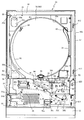
以下、パチンコ遊技機(以下、単に「パチンコ機」という)の一実施形態を、図面に基づいて詳細に説明する。図1はパチンコ機10の正面図であり、図2は前面枠14と下皿ユニット15とが開放されたパチンコ機10の斜視図である。図3はパチンコ機10の遊技盤16の正面図である。ここで、図2においては、便宜上、遊技盤16及びガラスユニット17を省略して示している。
Hereinafter, an embodiment of a pachinko gaming machine (hereinafter simply referred to as “pachinko machine”) will be described in detail with reference to the drawings. FIG. 1 is a front view of the pachinko machine 10, and FIG. 2 is a perspective view of the pachinko machine 10 in which the front frame 14 and the lower dish unit 15 are opened. FIG. 3 is a front view of the game board 16 of the pachinko machine 10. Here, in FIG. 2, for convenience, the game board 16 and the glass unit 17 are omitted.
パチンコ機10は、図1及び図2に示すように、略矩形状に組み合わせた木枠20(図4(a)参照)により外殻が形成される外枠12と、その外枠12と略同一の外形形状に形成された内枠13とを備えている。内枠13は、その中央部に略円形に開口した中央窓30aを有する合成樹脂製の内枠ベース30に通路形成部材36や球発射ユニット90等を取り付けたものである。内枠13には、多数の釘や入賞口63,64等を有する遊技盤16が裏面側から取り付けられ、内枠13の中央窓30aより遊技盤16の前面が視認可能となっている。この遊技盤16の前面を遊技球が流下することにより弾球遊技が行われる。
As shown in FIGS. 1 and 2, the pachinko machine 10 includes an outer frame 12 having an outer shell formed by a wooden frame 20 (see FIG. 4A) combined in a substantially rectangular shape, and the outer frame 12 and the outer frame 12. And an inner frame 13 formed in the same outer shape. The inner frame 13 is obtained by attaching a passage forming member 36, a ball launching unit 90, and the like to an inner frame base 30 made of synthetic resin having a central window 30a opened in a substantially circular shape at the center thereof. A game board 16 having a large number of nails, winning holes 63, 64, and the like is attached to the inner frame 13 from the back side, and the front surface of the game board 16 is visible from the central window 30a of the inner frame 13. A game ball is played by the game ball flowing down the front of the game board 16.
また、内枠13は、その一側(パチンコ機10においては正面視左側)の上下2箇所で外枠12に軸支され、内枠13が正面手前側へ開放可能に取り付けられている。内枠13の前面側には、その前面上側を覆う前面枠14と、その下側を覆う下皿ユニット15とが設けられ、これら前面枠14及び下皿ユニット15は内枠13の前面を開閉可能に取り付けられている。
In addition, the inner frame 13 is pivotally supported by the outer frame 12 at two upper and lower portions on one side thereof (left side in front view in the pachinko machine 10), and the inner frame 13 is attached so as to be openable to the front front side. On the front side of the inner frame 13, there are provided a front frame 14 that covers the upper side of the front surface and a lower dish unit 15 that covers the lower side of the inner frame 13. The front frame 14 and the lower dish unit 15 open and close the front surface of the inner frame 13. It is attached as possible.
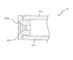
前面枠14は、合成樹脂製の前面枠ベース200に装飾用の樹脂部品や電気部品等を組み付けたものであり、その略中央部には、略円形状の開口(窓部14c)が形成されている。前面枠14の裏面側には2枚の板ガラス151を有するガラスユニット17(図13参照)が配設され、その板ガラス151を介して遊技盤16の前面がパチンコ機10の正面側に視認可能となっている。
The front frame 14 is obtained by assembling decorative resin parts, electrical parts, and the like on a synthetic resin front frame base 200, and a substantially circular opening (window 14c) is formed at a substantially central portion thereof. ing. A glass unit 17 (see FIG. 13) having two sheet glasses 151 is disposed on the rear surface side of the front frame 14, and the front surface of the game board 16 is visible on the front side of the pachinko machine 10 through the sheet glass 151. It has become.
前面枠14には、遊技球を貯留する上皿201が前方へ張り出して上面を開放した略箱状に形成されており、この上皿201に賞球や貸出球などが排出される。上皿201の底面は、遊技球を発射するための球発射ユニット90が位置する正面視右側に下降傾斜して形成され、上皿201に投入された遊技球は球発射ユニット90へと案内される。
On the front frame 14, an upper plate 201 for storing game balls is formed in a substantially box shape projecting forward and opening the upper surface, and prize balls, rental balls and the like are discharged to the upper plate 201. The bottom surface of the upper plate 201 is formed to be inclined downward to the right of the front view where the ball launch unit 90 for launching the game ball is located, and the game ball thrown into the upper plate 201 is guided to the ball launch unit 90. The
上皿201の下側に位置する下皿ユニット15には、その中央部に上皿201に貯留しきれなかった遊技球を貯留するための下皿301が上面を開放した略箱状に形成されている。下皿301の右側には、遊技球を遊技盤16の前面へ打ち込むために遊技者によって操作される操作ハンドル310が配設され、かかる操作ハンドル310の内部には球発射ユニット90の発射ソレノイド92の駆動を許可するためのタッチセンサと、操作ハンドル310の回動操作量を電気抵抗の変化により検出する可変抵抗器とが内蔵されている。操作ハンドル310が遊技者によって右回りに回転操作されると、タッチセンサがオンされると共に可変抵抗器の抵抗値が操作量に対応して変化する。発射ソレノイド92は、操作ハンドル310の回動操作量に応じて変化する可変抵抗器の抵抗値に対応した強さで遊技球を発射するものであり、これにより遊技者の操作に対応した飛び量で遊技盤16の前面へ遊技球が打ち込まれる。
In the lower tray unit 15 located on the lower side of the upper tray 201, a lower tray 301 for storing game balls that could not be stored in the upper tray 201 is formed in a substantially box shape with the upper surface open at the center. ing. On the right side of the lower plate 301, an operation handle 310 operated by a player to drive a game ball into the front surface of the game board 16 is disposed. Inside the operation handle 310, a launch solenoid 92 of the ball launch unit 90 is provided. And a variable resistor that detects the amount of rotation of the operation handle 310 based on a change in electrical resistance. When the operation handle 310 is rotated clockwise by the player, the touch sensor is turned on and the resistance value of the variable resistor changes corresponding to the operation amount. The firing solenoid 92 is for firing a game ball with a strength corresponding to the resistance value of the variable resistor that changes in accordance with the amount of rotation of the operation handle 310, whereby the jump amount corresponding to the operation of the player Then, a game ball is driven into the front of the game board 16.
遊技盤16は、図3に示すように、正面視略正方形状に切削加工した木製のベース板60に、遊技球案内用の多数の釘およびレール61,62、一般入賞口63、並びに、液晶ディスプレイ(以下単に「LCD」と略す。)で構成される第1図柄表示装置81等を組み付けて構成される。遊技盤16の前面には、帯状の金属板を略円弧状に屈曲加工して形成した外レール62が植立され、その外レール62の内側位置には外レール62と同様に帯状の金属板で形成した円弧状の内レール61が植立される。この内レール61と外レール62とにより遊技盤16の前面外周が囲まれ、遊技盤16とガラスユニット17(板ガラス151)とにより前後が囲まれることにより、遊技盤16の前面には、遊技球の挙動により遊技が行われる遊技領域が形成される。
As shown in FIG. 3, the game board 16 includes a wooden base plate 60 cut into a substantially square shape when viewed from the front, a large number of nails and rails 61 and 62 for guiding a game ball, a general winning opening 63, and a liquid crystal display. The first symbol display device 81 and the like configured by a display (hereinafter simply referred to as “LCD”) are assembled. An outer rail 62 formed by bending a strip-shaped metal plate into a substantially arc shape is planted on the front surface of the game board 16, and the strip-shaped metal plate is located at an inner position of the outer rail 62 in the same manner as the outer rail 62. The arc-shaped inner rail 61 formed by the above is planted. The inner periphery of the game board 16 is surrounded by the inner rail 61 and the outer rail 62, and the front and rear are surrounded by the game board 16 and the glass unit 17 (the plate glass 151). A game area in which a game is played is formed by the behavior of.
遊技領域には、遊技球が入賞することにより5個から15個の球が賞球として払い出される複数の一般入賞口63が配設されている。また、遊技領域の中央部分には、第1図柄表示装置81を有する可変表示装置ユニット80が配設され、この可変表示装置ユニット80が後述する表示制御装置505によって制御されることにより、複数種類の識別情報としての図柄が予め定めた順序に従って変動する変動表示が第1図柄表示装置81の表示画面上に表示される。なお、LCDに代えて、例えば、リール等を用いて第1図柄表示装置81を構成するようにしても良い。
The game area is provided with a plurality of general winning ports 63 through which 5 to 15 balls are paid out as prize balls when a game ball wins. Further, a variable display device unit 80 having a first symbol display device 81 is disposed in the central portion of the game area, and the variable display device unit 80 is controlled by a display control device 505 described later, so that a plurality of types can be obtained. A variation display in which the symbols as the identification information vary according to a predetermined order is displayed on the display screen of the first symbol display device 81. Instead of the LCD, for example, the first symbol display device 81 may be configured using a reel or the like.
可変表示装置ユニット80の下方には、遊技球が入球し得る第1入球口64が配設されている。この第1入球口64へ遊技球が入球すると遊技盤16の裏面側に設けられる第1入球口スイッチ524(図22参照)がオンとなり、上述した第1図柄表示装置81で図柄の変動表示が開始される。また、第1入球口64は、遊技球が入球すると5個の遊技球が賞球として払い出される入賞口の1つにもなっている。
Below the variable display unit 80, a first entrance 64 into which a game ball can enter is disposed. When a game ball enters the first entrance 64, the first entrance switch 524 (see FIG. 22) provided on the back side of the game board 16 is turned on, and the symbol is displayed on the first symbol display device 81 described above. Fluctuation display is started. The first entrance 64 is also one of the entrances through which 5 game balls are paid out as prize balls when game balls enter.
第1入球口64の下方には可変入賞装置65が配設されており、その略中央部分に横長矩形状の特定入賞口(大開放口)65aが設けられている。パチンコ機10においては、第1入球口への遊技球の入球を契機とした抽選が行われ、その抽選に当選すると大当たりとなって、第1図柄表示装置81には図柄の変動後に予め定められた図柄の組み合わせの1つが表示されて遊技者に大当たりの発生が示され、その後、遊技球が入賞し易い特別遊技状態に遊技状態が遷移する。この特別遊技状態として、通常時には閉鎖されている特定入賞口65aが、所定時間(例えば、30秒経過するまで、或いは、遊技球が10個入賞するまで)開放される。
A variable winning device 65 is disposed below the first ball opening 64, and a horizontally-long rectangular specific winning port (large opening) 65a is provided at a substantially central portion thereof. In the pachinko machine 10, a lottery is performed in response to a game ball entering the first entrance, and when the lottery is won, the first symbol display device 81 has a pre-change after the symbol changes. One of the determined symbol combinations is displayed to indicate to the player that the jackpot has been generated, and then the gaming state transitions to a special gaming state in which the game ball is easy to win. As this special gaming state, the special winning opening 65a that is normally closed is opened for a predetermined time (for example, until 30 seconds elapses or 10 game balls are won).
この特定入賞口65a内には、通常領域と、特定領域としてのVゾーンとが区分けして設けられており、特定入賞口65aの開放中に、遊技球がVゾーンを通過すると、継続権が成立して、特定入賞口65aの閉鎖後、再度、その特定入賞口65aが所定時間開放される。この特定入賞口65aの開閉動作は、最高で例えば16回(16ラウンド)繰り返し可能にされている。この開閉動作が行われている状態が、遊技者にとって有利な特別遊技状態の一形態であり、遊技者には、遊技上の価値(遊技価値)の付与として通常時より多量の賞球の払い出しが行われる。
In the specific winning opening 65a, a normal area and a V zone as a specific area are separately provided. If the game ball passes through the V zone while the specific winning opening 65a is opened, the continuation right is granted. After the establishment of the specific winning opening 65a, the specific winning opening 65a is opened again for a predetermined time. The opening / closing operation of the specific winning opening 65a can be repeated up to 16 times (16 rounds), for example. The state in which the opening / closing operation is performed is a form of a special gaming state advantageous to the player, and the player is given out a larger amount of prize balls than usual in order to give a gaming value (game value). Is done.
なお、上記した形態に特別遊技状態は限定されるものではない。特定入賞口65aとは別に開閉される大開放口を遊技領域に設け、第1図柄表示装置81の変動後の表示結果が予め定められた図柄の組み合わせの1つと一致する場合に、特定入賞口65aが所定時間開放され、その特定入賞口65aの開放中に、遊技球が特定入賞口65a内へ入賞することを契機として特定入賞口65aとは別に設けられた大開放口が所定時間、所定回数開放される遊技状態を特別遊技状態として形成するようにしても良い。
Note that the special gaming state is not limited to the above-described form. When the game area has a large opening that is opened and closed separately from the specific winning opening 65a, and the display result after the change of the first symbol display device 81 matches one of the predetermined symbol combinations, the specific winning opening 65a is opened for a predetermined time, and when the specific winning opening 65a is opened, a large opening provided separately from the specific winning opening 65a is predetermined for a predetermined time when the game ball wins into the specific winning opening 65a. A gaming state that is released a number of times may be formed as a special gaming state.
次に、パチンコ機10の構成について外枠12、内枠13、遊技盤16、前面枠14、下皿ユニット15、ガラスユニット17に大別して順に説明し、その後、パチンコ機10の背面側の構成について説明する。まず、外枠12の構成について図2および図4を主に参照して説明する。ここで、図4(a)は、外枠12の斜視図であり、図4(b)は外枠12の受け金具23周辺を拡大して示した斜視図である。
Next, the configuration of the pachinko machine 10 will be roughly divided into an outer frame 12, an inner frame 13, a game board 16, a front frame 14, a lower tray unit 15, and a glass unit 17, and then the configuration on the back side of the pachinko machine 10. Will be described. First, the configuration of the outer frame 12 will be described with reference mainly to FIGS. 2 and 4. Here, FIG. 4A is a perspective view of the outer frame 12, and FIG. 4B is an enlarged perspective view of the periphery of the receiving bracket 23 of the outer frame 12.
図2に示すように、パチンコ機10には、その外殻を形成する外枠12が設けられ、この外枠20に対して内枠13が開閉可能に支持される。遊技場においては、外枠20の外周面が遊技場の島と呼ばれる設置箇所に固定される。内枠13、前面枠14および下皿ユニット15は、外枠12に対して前面側に開放可能に構成されるので、パチンコ機10の前面側からは触れられない裏面側や内部に対しての点検や調整は、外枠12に対して内枠13等を前面側に開放して行われる。
As shown in FIG. 2, the pachinko machine 10 is provided with an outer frame 12 that forms an outer shell, and the inner frame 13 is supported by the outer frame 20 so as to be opened and closed. In the game hall, the outer peripheral surface of the outer frame 20 is fixed to an installation location called an island of the game hall. Since the inner frame 13, the front frame 14, and the lower dish unit 15 are configured to be openable to the front side with respect to the outer frame 12, the inner frame 13, the front frame 14, and the lower dish unit 15 are not touched from the front side of the pachinko machine 10. Inspection and adjustment are performed with the inner frame 13 and the like open to the front side with respect to the outer frame 12.
外枠12は、木製の板材で上下左右の四辺を構成して全体として矩形状の木枠20を形成し、その木枠20にヒンジ21,22と受け金具23,23とを取り付けたものである。木枠20の接合部は、小ネジ等の離脱可能な締結具により固定され、釘やリベットを使って固定する構造と比べて、木枠20の一部が容易に再利用できるようになっている。本実施の形態では、外枠12の上下方向の外寸は809mm(内寸約710mm)、左右方向の外寸は518mm(内寸約480mm)となっている。なお、外枠12は、アルミニウム等の軽金属や樹脂により構成するようにしてもよい。
The outer frame 12 is made of a wooden plate material that forms four sides on the top, bottom, left, and right to form a rectangular wooden frame 20 as a whole, and hinges 21 and 22 and receiving brackets 23 and 23 are attached to the wooden frame 20. is there. The joint portion of the wooden frame 20 is fixed by a detachable fastener such as a small screw, and a part of the wooden frame 20 can be easily reused as compared with a structure that is fixed using a nail or a rivet. Yes. In the present embodiment, the outer dimension of the outer frame 12 is 809 mm (inner dimension of about 710 mm), and the outer dimension of the left and right direction is 518 mm (inner dimension of about 480 mm). The outer frame 12 may be made of a light metal such as aluminum or a resin.
外枠12には、図4(a)に示すように、内枠13を支持するために正面視左側の上下2カ所に金属製の上ヒンジ21および下ヒンジ22が取り付けられている。このヒンジ21,22が設けられた側を開閉の軸として内枠13は開閉可能に支持される。
As shown in FIG. 4A, metal upper hinges 21 and lower hinges 22 are attached to the outer frame 12 at two upper and lower portions on the left side when viewed from the front to support the inner frame 13. The inner frame 13 is supported to be openable and closable by using the side on which the hinges 21 and 22 are provided as an opening / closing axis.
外枠12の受け金具23は、木枠20の内面であってヒンジ21,22から離間した側の一辺における上下2カ所にネジにより螺着されている。各受け金具23は、金属板を屈曲加工して形成され、図4(b)に示すように、外枠12の内面に密着する取付部23aと、その取付部23aから外枠12の内面側に向けて垂直に立ち上がる係合部23bと、その係合部23bの先端側にて内枠13の閉鎖方向側(図4(b)の左上側)に向けて突出して形成される突出部23cとを備えている。この受け金具23の係合部23bには、内枠13より鉤形に突出して形成される内枠用鉤部材411(図23参照)の先端部が引っ掛かり、内枠13は閉鎖される。
The metal fittings 23 of the outer frame 12 are screwed into the upper and lower two places on one side of the inner side of the wooden frame 20 and away from the hinges 21 and 22 with screws. Each receiving bracket 23 is formed by bending a metal plate, and as shown in FIG. 4B, a mounting portion 23a that is in close contact with the inner surface of the outer frame 12, and the inner surface side of the outer frame 12 from the mounting portion 23a. An engaging portion 23b that rises vertically toward the end, and a protruding portion 23c that protrudes toward the closing direction side of the inner frame 13 (upper left side in FIG. 4B) at the distal end side of the engaging portion 23b. And. The front end portion of the inner frame collar member 411 (see FIG. 23) formed so as to project from the inner frame 13 in a hook shape is caught in the engaging portion 23 b of the receiving metal 23, and the inner frame 13 is closed.
受け金具23の突出部23cは、外枠12に対して内枠13が閉鎖された状態にて、外枠12の内面側(図4(b)の左下側)に向かって、内枠用鉤部材411の下方に突出した先端部分に重なる長さ以上に突出して形成される。このため、内枠用鉤部材411の先端部は、突出部23cにより外枠12内面側への移動が規制され、外枠12内面側への受け金具23の突出量を少なくしつつ、内枠13のがたつきにより内枠用鉤部材411が誤って受け金具23から外れて、内枠13が不用意に開放されることが防止されている。
The protruding portion 23c of the metal fitting 23 has an inner frame flange toward the inner surface side (the lower left side in FIG. 4B) of the outer frame 12 in a state where the inner frame 13 is closed with respect to the outer frame 12. It is formed so as to protrude more than the length overlapping the tip portion protruding downward of the member 411. For this reason, the movement of the distal end portion of the inner frame collar member 411 toward the inner surface side of the outer frame 12 is restricted by the protruding portion 23c, and the protruding amount of the metal fitting 23 toward the inner surface side of the outer frame 12 is reduced. It is prevented that the inner frame collar member 411 is accidentally detached from the receiving metal fitting 23 due to the shakiness of 13 and the inner frame 13 is inadvertently opened.
外枠12の下側には、横長矩形の合成樹脂、具体的にはABS樹脂の板により形成された飾り板24が、木枠20を貫通するネジにより外枠12の背面側より固定されている。この飾り板24によって、パチンコ機10の前面側に露出する外枠12の大部分は、内枠13、前面枠14および下皿ユニット15と同様に合成樹脂製となり、各部材間に一体感が生まれて外観品質の向上が図られる。また、本実施形態においては省略するが、飾り板24の前面に下皿ユニット15の形状に倣って模様を付すことにより、外枠12の木製部分である木枠20を共用しつつ異なる外観形状を有する外枠12を製造することができ、木枠20を有効的に再利用しつつパチンコ機10の外観品質を向上することができる。
On the lower side of the outer frame 12, a decorative plate 24 formed of a horizontally long rectangular synthetic resin, specifically, an ABS resin plate, is fixed from the back side of the outer frame 12 by screws passing through the wooden frame 20. Yes. Due to the decorative plate 24, most of the outer frame 12 exposed to the front side of the pachinko machine 10 is made of synthetic resin like the inner frame 13, the front frame 14 and the lower plate unit 15, and a sense of unity is provided between the members. Born to improve appearance quality. Although omitted in the present embodiment, different external shapes are shared while sharing the wooden frame 20 which is the wooden portion of the outer frame 12 by applying a pattern following the shape of the lower dish unit 15 on the front surface of the decorative plate 24. Can be manufactured, and the appearance quality of the pachinko machine 10 can be improved while effectively reusing the wooden frame 20.
飾り板24の上面には、金属製の滑り板25,26が、ヒンジ22から離間した側の端部と中央部との2カ所に設けられている。開放状態の内枠13が自重により外枠12に対して下側に落ち込んでも、内枠13が閉鎖されるときには、その下面が滑り板25,26に擦られつつ持ち上げられて、内枠13は定位置に案内される。このため、作業者がわざわざ内枠13を持ち上げながら閉鎖操作を行う必要がなく、内枠13の開閉操作の利便性が高められている。また、樹脂または木製の部分で内枠13を定位置に案内する部分が形成される場合に比べて、開閉操作の繰り返しによる擦れによって部品が削られたり、破損したりすることが防止されるので、長期にわたって内枠13の開閉操作を容易に行うことができる。
On the upper surface of the decorative plate 24, metal sliding plates 25 and 26 are provided at two locations, that is, an end portion on the side separated from the hinge 22 and a central portion. Even if the inner frame 13 in the open state falls downward with respect to the outer frame 12 due to its own weight, when the inner frame 13 is closed, its lower surface is lifted while being rubbed against the sliding plates 25 and 26, and the inner frame 13 Guided to a fixed position. For this reason, it is not necessary for the operator to perform the closing operation while lifting the inner frame 13, and the convenience of the opening / closing operation of the inner frame 13 is enhanced. In addition, compared to the case where a part that guides the inner frame 13 to a fixed position is formed by a resin or wooden part, parts are prevented from being scraped or damaged due to rubbing due to repeated opening and closing operations. The opening / closing operation of the inner frame 13 can be easily performed over a long period of time.
これら2つの滑り板25,26のうち一方の滑り板26は、内枠13の開閉軸となるヒンジ21,22から離間した側の端部に設けられる。このため、金属製の下ヒンジ22と滑り板26とにより内枠13の下面両端側が支持され、内枠13がより安定した状態で定位置に案内される。また、もう1つの滑り板25は、ヒンジ22と滑り板26とのほぼ中間位置に設けられ、ヒンジ22と、端部に設けた滑り板26との支持により最も落ち込み易い部分が案内されることとなる。このように、2つの滑り板25,26を飾り板24の上面におけるヒンジ22から離間した側の端部と中央部とに設けることにより内枠13を定位置により確実に案内することができ、上皿201や下皿301に遊技球が多量に入る等して内枠13に負荷される重みが増大しても、内枠の開閉操作は容易に行うことができる。
One of the two sliding plates 25, 26 is provided at an end portion on the side away from the hinges 21, 22 serving as the opening / closing shaft of the inner frame 13. For this reason, both lower end sides of the inner frame 13 are supported by the metal lower hinge 22 and the sliding plate 26, and the inner frame 13 is guided to a fixed position in a more stable state. Further, the other sliding plate 25 is provided at a substantially intermediate position between the hinge 22 and the sliding plate 26, and the most easily depressed portion is guided by the support of the hinge 22 and the sliding plate 26 provided at the end. It becomes. Thus, by providing the two sliding plates 25 and 26 at the end portion and the central portion on the upper surface of the decorative plate 24 on the side away from the hinge 22, the inner frame 13 can be reliably guided at a fixed position, Even if the weight applied to the inner frame 13 increases due to a large amount of game balls entering the upper plate 201 or the lower plate 301, the opening / closing operation of the inner frame can be easily performed.
飾り板24の上面奥側には、パチンコ機10の前後方向に沿って内枠13の下端部に重なる位置まで上方に突出して形成されたリブ27が設けられている。また、リブ27の付け根部分には、飾り板24の上面に沿って背面側に窪んだ溝27aが形成され、リブ27の上端部がパチンコ機10の前面側に突出するように形成される。パチンコ機に対しては、薄板状の工具等を部材間の隙間から差し入れて行う不正行為が頻繁に報告されているが、本実施形態のパチンコ機10においては、内枠13の下側から工具等を差し入れる行為がリブ27により阻止されるので、不正行為を防止することができる。また、内枠13と飾り板24との間から差し入れた工具はリブ27の付け根部分に設けた溝27aに嵌まり易く、不正行為を一層困難なものとしている。
On the back side of the upper surface of the decorative plate 24, a rib 27 is provided so as to protrude upward to a position overlapping the lower end portion of the inner frame 13 along the front-rear direction of the pachinko machine 10. In addition, a groove 27 a that is recessed toward the back side along the upper surface of the decorative plate 24 is formed at the base portion of the rib 27, and the upper end portion of the rib 27 is formed so as to protrude toward the front side of the pachinko machine 10. For pachinko machines, fraudulent acts that are performed by inserting a thin plate-like tool or the like through a gap between members are frequently reported. However, in the pachinko machine 10 according to the present embodiment, a tool from the lower side of the inner frame 13 is reported. Since the rib 27 prevents the act of inserting etc., fraudulent acts can be prevented. Further, the tool inserted from between the inner frame 13 and the decorative plate 24 is likely to be fitted into the groove 27a provided at the base portion of the rib 27, which makes it more difficult to cheat.
飾り板24上面のリブ27の高さは、飾り板24の上面に対して遊技球の半径より低く設定されている。このため、内枠13の閉鎖時に飾り板24の上面に遊技球が乗っていても、その遊技球は、内枠13の下端部とリブ27との間に挟まれた後にリブ27を乗り越える。よって、リブ27を設けることにより不正行為を防止しつつ、リブ27と内枠13との間に遊技球が挟み込まれて内枠13を閉鎖し直す手間が発生することもなく、内枠13の開閉操作に対する利便性を高く維持することができる。
The height of the ribs 27 on the upper surface of the decorative plate 24 is set lower than the radius of the game ball with respect to the upper surface of the decorative plate 24. For this reason, even if a game ball is on the upper surface of the decorative plate 24 when the inner frame 13 is closed, the game ball gets over the rib 27 after being sandwiched between the lower end portion of the inner frame 13 and the rib 27. Therefore, the provision of the rib 27 prevents illegal actions, and the game ball is not sandwiched between the rib 27 and the inner frame 13 so that the trouble of reclosing the inner frame 13 does not occur. Convenience for the opening / closing operation can be kept high.
次に、図2および図5を主に参照して内枠13について説明する。図5は、前面枠14および下皿セット15を取り外した状態のパチンコ機10の正面図である。また、図5では、便宜上、遊技盤16面上の遊技領域内の構成の一部を空白で示している。
Next, the inner frame 13 will be described mainly with reference to FIGS. 2 and 5. FIG. 5 is a front view of the pachinko machine 10 with the front frame 14 and the lower dish set 15 removed. In FIG. 5, for convenience, a part of the configuration in the game area on the surface of the game board 16 is shown as blank.
内枠13は、矩形状に形成されたABS樹脂製の内枠ベース30を主体に構成されており、内枠ベース30の中央部には略円形状の中央窓30aが形成されている。内枠ベース30の裏面側には遊技盤16の取付部が設けられ、遊技盤16が着脱可能に装着される。
The inner frame 13 is mainly composed of an ABS resin-made inner frame base 30 formed in a rectangular shape, and a substantially circular central window 30 a is formed at the center of the inner frame base 30. An attachment portion for the game board 16 is provided on the back side of the inner frame base 30, and the game board 16 is detachably attached.
内枠13は、前述した外枠12の上ヒンジ21および下ヒンジ22により、外枠12に対して回動可能に支持された扉状の部材である。内枠13の開閉軸線は、ヒンジ21,22が設けられるパチンコ機10の正面視左側に上下に延設され、この開閉軸線を軸心にして内枠13は前方側に開放される。内枠13の開閉軸線は、パチンコ機10の正面視右側に設けられる操作ハンドル310(図1参照)とは反対側(正面視左側)に設定され、内枠13がより大きく開放できるようになっている。通常パチンコホールでは、パチンコ機10は互いに隣接して配設されるので、開閉軸線を操作ハンドル310側に設けると、内枠13の開放と共に移動する操作ハンドル310が隣のパチンコ機10や、パチンコ機10の間に設けられるカードユニット等に当接して開放量が制限されるからである。
The inner frame 13 is a door-shaped member that is rotatably supported with respect to the outer frame 12 by the upper hinge 21 and the lower hinge 22 of the outer frame 12 described above. The opening / closing axis of the inner frame 13 extends vertically on the left side of the front view of the pachinko machine 10 provided with the hinges 21, 22, and the inner frame 13 is opened to the front side with the opening / closing axis serving as an axis. The opening / closing axis of the inner frame 13 is set on the side (left side in front view) opposite to the operation handle 310 (see FIG. 1) provided on the right side in front view of the pachinko machine 10 so that the inner frame 13 can be opened more greatly. ing. Normally, in the pachinko hall, the pachinko machines 10 are arranged adjacent to each other. Therefore, when the opening / closing axis is provided on the operation handle 310 side, the operation handle 310 that moves along with the opening of the inner frame 13 moves to the adjacent pachinko machine 10 or the pachinko machine. This is because the amount of opening is limited by contacting a card unit or the like provided between the machines 10.
内枠13の外周には、前面側へ突設された外周壁30bが形成されており、その外周壁30bの内側に前面枠14および下皿ユニット15が配設される。即ち、内枠13に前面枠14および下皿ユニット15が取り付けられた状態では、前面枠14および下皿ユニット15の各側面の外周は、内枠13の外周壁30bにより囲繞される。このため、前面枠14または下皿ユニット15と、内枠13との間へ針金や薄板状の工具等を挿入する行為が困難となり、不正行為を抑制することができる。
An outer peripheral wall 30b is formed on the outer periphery of the inner frame 13 so as to project to the front side, and the front frame 14 and the lower dish unit 15 are disposed inside the outer peripheral wall 30b. That is, in a state where the front frame 14 and the lower dish unit 15 are attached to the inner frame 13, the outer periphery of each side surface of the front frame 14 and the lower dish unit 15 is surrounded by the outer peripheral wall 30 b of the inner frame 13. For this reason, it becomes difficult to insert a wire or a thin plate-like tool between the front frame 14 or the lower tray unit 15 and the inner frame 13, and it is possible to suppress fraud.
内枠13の左上部には、図2に示すように、配線口30cが内枠ベース30を貫通して設けられている。配線口30cには、前面枠14の電飾等に使用する部品の配線が内枠13の裏面側に挿通され、遊技盤16の裏面に接続される。配線口30cの角部にはRが形成されており、配線口30c内に配線される各コードが、前面枠14の開閉により配線口30cで擦られても損傷し難くなっている。なお、遊技盤16(ベース板60)にも、内枠13の配線口30cに対応する位置(左上部)に配線口60aが設けられ、内枠ベース30に遊技盤16が取り付けられた状態にて配線が可能となっている。
As shown in FIG. 2, a wiring port 30 c is provided through the inner frame base 30 in the upper left portion of the inner frame 13. In the wiring port 30 c, wiring of components used for electrical decoration or the like of the front frame 14 is inserted into the back side of the inner frame 13 and connected to the back side of the game board 16. Rs are formed at the corners of the wiring port 30c, and even if each cord wired in the wiring port 30c is rubbed by the wiring port 30c by opening and closing the front frame 14, it is difficult to be damaged. The game board 16 (base plate 60) is also provided with a wiring port 60a at a position (upper left) corresponding to the wiring port 30c of the inner frame 13, and the gaming board 16 is attached to the inner frame base 30. Wiring is possible.
内枠13の配線口30cの右上側には、パチンコ機10の前面側に円柱状に突出した押しボタン型の開閉スイッチ32が設けられている。開閉スイッチ32は、前面枠14の開閉状態を検出するためのスイッチである。前面枠14が内枠13に対して閉じられている場合には開閉スイッチ32が前面枠14の裏面に押圧されて押し込まれた状態となり、逆に、前面枠14が内枠13に対して開放されている場合には開閉スイッチ32は非押圧の突出状態となって、前面枠14の開閉状態を検出する。この開閉スイッチ32は、パチンコ機10裏面側の外部出力用の端子を介して、パチンコ機10の上側に一般に設けられるランプや、遊技場に設置される複数の遊技機を一括管理する島管理装置等に接続される。これにより、複数のパチンコ機10のうち、開放状態となっているパチンコ機10だけ、特別にランプを点灯させたり、島管理装置に信号を送って監視カメラで開放中のパチンコ機10を拡大して表示画面に表示したりして、パチンコ機10の不正開放に対する防犯性が高められる。
On the upper right side of the wiring port 30 c of the inner frame 13, a push button type opening / closing switch 32 protruding in a columnar shape is provided on the front side of the pachinko machine 10. The open / close switch 32 is a switch for detecting the open / closed state of the front frame 14. When the front frame 14 is closed with respect to the inner frame 13, the open / close switch 32 is pressed against the back surface of the front frame 14, and conversely, the front frame 14 is opened with respect to the inner frame 13. If it is, the open / close switch 32 is in a non-pressing protruding state, and detects the open / closed state of the front frame 14. This open / close switch 32 is an island management device that collectively manages lamps generally provided on the upper side of the pachinko machine 10 and a plurality of gaming machines installed in the game hall via an external output terminal on the back side of the pachinko machine 10. Connected to etc. As a result, among the plurality of pachinko machines 10, only the pachinko machine 10 in the open state is turned on specially or a signal is sent to the island management device to enlarge the pachinko machine 10 being opened by the surveillance camera. The security against the unauthorized opening of the pachinko machine 10 is improved.
内枠13の中央窓30aの右下側には、略四角形状の小窓30dが内枠ベース30を貫通して設けられ、また中央窓30aの左下側にも略正方形の一部を面取りした形状の小窓30eが内枠ベース30を貫通して設けられている。遊技盤16の下側における左右の隅部には、証紙や識別ラベル等を貼着するための貼着スペースK1,K2(図3参照)が設けられ、貼着スペースK1,K2に貼られた証紙等は、内枠13の小窓30d,30eを通じて内枠13の前面側に露出されるので、前面枠14を開放した状態において証紙等を視認することができる。又、内枠ベース30に遊技盤16が取り付けられた後にも、小窓30d,30eを通じて遊技盤16の貼着スペースK1,K2に証紙等を貼着することができる。
A substantially rectangular small window 30d is provided through the inner frame base 30 on the lower right side of the central window 30a of the inner frame 13, and a part of a substantially square is chamfered on the lower left side of the central window 30a. A small window 30 e having a shape is provided through the inner frame base 30. Adhesive spaces K1, K2 (see FIG. 3) for adhering certificate stamps, identification labels, etc. are provided at the left and right corners on the lower side of the game board 16, and are attached to the adhering spaces K1, K2. Since the certificate paper or the like is exposed to the front side of the inner frame 13 through the small windows 30d and 30e of the inner frame 13, the certificate paper or the like can be viewed with the front frame 14 opened. In addition, even after the game board 16 is attached to the inner frame base 30, it is possible to stick a stamp or the like on the sticking spaces K 1 and K 2 of the game board 16 through the small windows 30 d and 30 e.
内枠ベース30の中央窓30aの下側は、前面側が開放した凹状に窪んで形成されており、その奥側には、平面状の取付面30fが形成されている。取付面30fには、遊技球を遊技盤16の前面に発射するための球発射ユニット90や、上皿201および下皿301に遊技球を排出する通路を形成する通路形成部材36等が取り付けられる。
The lower side of the central window 30a of the inner frame base 30 is formed in a concave shape with the front side open, and a flat mounting surface 30f is formed on the back side. A ball launching unit 90 for launching a game ball to the front surface of the game board 16, a passage forming member 36 that forms a passage for discharging the game ball to the upper plate 201 and the lower plate 301, and the like are attached to the attachment surface 30f. .
内枠13の左端部には、図5に示すように、前面枠14および下皿ユニット15を支持するための機構として、縦方向に沿った3カ所に3つの支持金具33〜35が取り付けられている。上側の支持金具33には図5の紙面手前側にU字状に開口すると共にその入口が奥側より幅狭に形成された切欠を有する支持孔33aが設けられ、その支持孔33aに段付きの円柱状に形成された前面枠14側の支持金具33が嵌合する。
As shown in FIG. 5, three support fittings 33 to 35 are attached to the left end portion of the inner frame 13 at three locations along the vertical direction as a mechanism for supporting the front frame 14 and the lower dish unit 15. ing. The upper support fitting 33 is provided with a support hole 33a having a notch formed with a U-shaped opening on the front side of the sheet of FIG. 5 and having an inlet formed narrower than the back side. The support hole 33a is stepped. The support bracket 33 on the front frame 14 side formed in a cylindrical shape is fitted.
上から2番目の支持金具34には、上下方向にそれぞれ突出した円柱状の突起軸34a,34bが設けられる。2本の突起軸34a,34bのうち上側に突出した突起軸34aにより前面枠14の左下隅が回動可能に支持され、下側に突出した突起軸34bにより下皿ユニット15の左上隅が内枠13に対して回動可能に支持される。
The second support bracket 34 from the top is provided with cylindrical projection shafts 34a and 34b that protrude in the vertical direction. The lower left corner of the front frame 14 is rotatably supported by the protrusion shaft 34a protruding upward from the two protrusion shafts 34a and 34b, and the upper left corner of the lower plate unit 15 is internally supported by the protrusion shaft 34b protruding downward. The frame 13 is supported so as to be rotatable.
一番下側の支持金具35は、内枠13の前面側に向けて突出した水平な金属板に上下方向に貫通する支持孔を設けて形成される。下皿ユニット15の左端部下側には、ばねにより下側に突出するように付勢力が付与される支持軸308(図19参照)が設けられ、その支持軸307が支持金具35の支持孔に軸支されて下皿ユニット15の左下隅が内枠13に対して回動可能に支持される。
The lowermost support fitting 35 is formed by providing a support hole penetrating in a vertical direction in a horizontal metal plate protruding toward the front side of the inner frame 13. A support shaft 308 (see FIG. 19) to which an urging force is applied so as to protrude downward by a spring is provided on the lower side of the left end portion of the lower dish unit 15, and the support shaft 307 is provided in the support hole of the support fitting 35. The lower left corner of the lower plate unit 15 is pivotally supported so as to be rotatable with respect to the inner frame 13.
次に、図3を主に参照して遊技盤16の構成を説明する。遊技盤16は、四角形状の合板で形成されたベース板60に釘や風車、入賞口63等を組み付けて構成され、その周縁部が内枠ベース30の裏側に当接した状態で内枠13の裏面側に取り付けられる。遊技盤16の前面中央部分は、内枠ベース30の中央窓30aを通じて内枠13の前面側に露出される。なお、遊技盤16の上下方向の長さは約480mm、左右方向の長さは約450mmとされ、従来と同等のサイズとなっている。
Next, the configuration of the game board 16 will be described with reference mainly to FIG. The game board 16 is configured by assembling a base plate 60 formed of a quadrangular plywood with a nail, a windmill, a winning opening 63, and the like, and the inner frame 13 with its peripheral edge abutting against the back side of the inner frame base 30. It is attached to the back side. The front center portion of the game board 16 is exposed to the front side of the inner frame 13 through the central window 30 a of the inner frame base 30. The vertical length of the game board 16 is about 480 mm, and the length in the left-right direction is about 450 mm, which is the same size as the conventional one.
遊技盤16には、上述した一般入賞口63、第1入球口64、可変入賞装置65、可変表示装置ユニット80等がルータ加工によってベース板60に形成された貫通穴に配設され、遊技盤16の前面側から木ネジ等により固定されている。また、前記した入賞口以外に、遊技盤16には、アウト口66と第2入球口(スルーゲート)67とが設けられている。いずれの入賞口63,64,65aにも入球しなかった遊技球はアウト口66を通って図示しない球排出路へと案内される。遊技盤16には、遊技球の落下方向を適宜分散、調整等するために多数の釘が植設されているとともに、風車等の各種部材(役物)が配設されている。
The game board 16 is provided with the above-described general winning opening 63, first winning opening 64, variable winning device 65, variable display device unit 80, etc. disposed in a through hole formed in the base plate 60 by router processing. It is fixed from the front side of the panel 16 with wood screws or the like. In addition to the above-described winning opening, the game board 16 is provided with an out opening 66 and a second entrance (through gate) 67. The game balls that have not entered any of the winning openings 63, 64, 65a are guided through the out opening 66 to a ball discharge path (not shown). A number of nails are planted on the game board 16 in order to appropriately disperse and adjust the falling direction of the game ball, and various members (instruments) such as a windmill are arranged.
可変表示装置ユニット80には、第2入球口67の遊技球の通過をトリガとして第2図柄(普通図柄)を変動表示する発光ダイオード(以下、「LED」と略す。)で構成される第2図柄表示装置82と、第1入球口64への入賞をトリガとして第1図柄(特別図柄)を変動表示する第1図柄表示装置81とが設けられている。第2図柄表示装置82は、第2図柄の表示部83と保留ランプ84とを有し、遊技球が第2入球口67を通過する毎に、表示部83において表示図柄(第2図柄)としての「○」の図柄と「×」の図柄とが交互に点灯して変動表示が行われ、その変動表示が所定図柄(本実施形態においては「○」の図柄)で停止した場合に第1入球口64が所定時間だけ作動状態となる(開放される)よう構成されている。遊技球の第2入球口67の通過回数は最大4回まで保留され、その保留回数が保留ランプ84に点灯表示される。なお、第2図柄の変動表示は、本実施の形態のように、表示部83において複数のランプの点灯と非点灯を切り換えることにより行うものの他、第1図柄表示装置81の一部を使用して行うようにしても良い。同様に、保留ランプ84の点灯についても、第1図柄表示装置81の一部で行うようにしても良い。
The variable display device unit 80 includes a light emitting diode (hereinafter abbreviated as “LED”) that displays the second symbol (ordinary symbol) in a variable manner with the passage of the game ball at the second entrance 67 as a trigger. There are provided a two symbol display device 82 and a first symbol display device 81 for variably displaying the first symbol (special symbol) triggered by winning at the first entrance 64. The second symbol display device 82 includes a second symbol display portion 83 and a holding lamp 84, and each time a game ball passes through the second entrance 67, the display symbol 83 displays a second symbol (second symbol). As the symbol “○” and “×” symbol are alternately lit, the variable display is performed, and when the variable display stops at a predetermined symbol (in this embodiment, “○” symbol) The 1 entrance 64 is configured to be activated (opened) for a predetermined time. The number of times that the game ball passes through the second entrance 67 is held up to a maximum of 4 times, and the number of times the game ball is passed is displayed on the hold lamp 84. Note that the variation display of the second symbol is performed by switching on and off of a plurality of lamps in the display unit 83 as in the present embodiment, and a part of the first symbol display device 81 is used. May be performed. Similarly, the hold lamp 84 may be turned on by a part of the first symbol display device 81.
また、第1図柄表示装置81にて第1図柄の変動表示が行われている間に遊技球が第1入球口64へ入球した場合、その入球回数は最大4回まで保留され、その保留回数は保留ランプ85の点灯個数にて表示される。保留ランプ85は、最大保留数分の4つ設けられ、第1図柄表示装置81の上方に左右対称に配設されている。なお、本実施形態においては、第1入球口64への入賞および第2入球口67の通過は、それぞれ最大4回まで保留されるように構成したが、最大保留回数は4回に限定されるものでなく、3回以下、又は、5回以上の回数(例えば、8回)に設定しても良い。また、保留ランプ85を削除し、第1入球口64への入賞に基づく変動表示の保留回数を第1図柄表示装置81の一部に数字で、或いは、4つに区画された領域を保留回数分だけ異なる態様(例えば、色や点灯パターン)にして表示するようにしても良い。
In addition, when a game ball enters the first entrance 64 while the first symbol display device 81 is performing the variable display of the first symbol, the number of times that the ball has entered is suspended up to four times, The number of times of holding is displayed by the number of lighting of the holding lamp 85. Four holding lamps 85 are provided for the maximum number of holdings, and are arranged symmetrically above the first symbol display device 81. In the present embodiment, the winning entry to the first entrance 64 and the passing through the second entrance 67 are configured to be held up to 4 times each, but the maximum holding number is limited to 4 times. Instead, it may be set to 3 times or less, or 5 times or more (for example, 8 times). In addition, the hold lamp 85 is deleted, and the number of times the variable display is held based on the winning at the first entrance 64 is numerically held in a part of the first symbol display device 81, or the area divided into four is held. You may make it display in a different aspect (for example, a color and a lighting pattern) by the frequency | count.
第1図柄表示装置81は、後述する表示制御装置505によって表示内容が制御され、、例えば左、中及び右の3つの図柄列が表示される。各図柄列は複数の図柄によって構成され、これらの図柄が図柄列毎に縦スクロールして第1図柄表示装置81の表示画面上にて第1図柄が可変表示されるようになっている。なお、本実施形態では、第1図柄表示装置81は8インチサイズの大型の液晶ディスプレイで構成され、可変表示装置ユニット80には、この第1図柄表示装置81の外周を囲むようにして、センターフレーム86が配設されている。
The display content of the first symbol display device 81 is controlled by a display control device 505, which will be described later, and for example, three symbol sequences of left, middle, and right are displayed. Each symbol row is composed of a plurality of symbols, and these symbols are vertically scrolled for each symbol row so that the first symbol is variably displayed on the display screen of the first symbol display device 81. In the present embodiment, the first symbol display device 81 is composed of a large liquid crystal display of 8 inch size, and the variable display device unit 80 surrounds the outer periphery of the first symbol display device 81 so as to surround the center frame 86. Is arranged.
可変入賞装置65は、その中央部に横長矩形状に形成された特定入賞口65aを開閉するものである。具体的には、特定入賞口65aを覆う横長矩形状の開閉板と、その開閉板の下辺を軸として前方側に開閉駆動するためのソレノイドとを備えている。特定入賞口65aは、通常時は、遊技球が入賞できないか又は入賞し難い閉状態になっている。大当たりの際にはソレノイドを駆動して開閉板を前面下側に傾倒し、遊技球が特定入賞口65aに入賞しやすい開状態を一時的に形成し、その開状態と通常時の閉状態との状態を交互に繰り返すように作動する。
The variable winning device 65 opens and closes a specific winning port 65a formed in a horizontally long rectangular shape at the center thereof. Specifically, a horizontally long rectangular opening / closing plate that covers the specific winning opening 65a, and a solenoid for opening / closing driving the lower side of the opening / closing plate as an axis are provided. The special winning opening 65a is normally closed so that a game ball cannot win or is difficult to win. In the case of a big hit, the solenoid is driven to tilt the opening / closing plate downward and the game ball temporarily forms an open state in which the game ball is likely to win the specific winning opening 65a. It operates so that these states are repeated alternately.
遊技盤16に設けられる2本のレール61,62は、球発射ユニット90から発射された遊技球を遊技盤16上部へ案内するために設けられたものである。操作ハンドル310の回動操作に伴い発射された遊技球は2本のレール61,62に挟まれた通路を経由して遊技領域に案内される。両レール61,62は、ステンレス製の金属帯によって構成され、内レール61は右上側の半円分を除いた円環状に曲げられた状態でベース板60に固定されている。外レール62は、その一部(主に左側部)が内レール61に向かい合うようにしてベース板60に固定されている。これら内レール61と外レール62とにより主として誘導レールが構成され、これら各レール61,62が所定間隔を隔てて並行する部分(向かって左側の部分)により、遊技球を遊技領域へ案内する球案内通路が形成される。
The two rails 61 and 62 provided on the game board 16 are provided for guiding the game balls launched from the ball launch unit 90 to the upper part of the game board 16. A game ball launched in accordance with the turning operation of the operation handle 310 is guided to the game area via a path sandwiched between the two rails 61 and 62. Both rails 61 and 62 are made of a stainless steel metal band, and the inner rail 61 is fixed to the base plate 60 in a state of being bent into an annular shape excluding the upper right semicircle. The outer rail 62 is fixed to the base plate 60 such that a part (mainly the left side portion) faces the inner rail 61. The inner rail 61 and the outer rail 62 mainly constitute a guide rail, and a ball that guides the game ball to the game area by a portion where the rails 61 and 62 are parallel to each other at a predetermined interval (a portion on the left side). A guide passage is formed.
内レール61の先端部分(図3の左上部)には戻り球防止部材68が取り付けられている。これにより、一旦、内レール61及び外レール62間の球案内通路から遊技盤16の上部へ案内された遊技球が再度球案内通路内に戻ってしまうといった事態が防止される。また、内レール61の右下側の先端部と外レール62の右上側の先端部との間には、レール間を繋ぐ円弧を内面側に設けて形成された樹脂製の円弧部材70がベース板60に打ち込んで固定されている。外レール62の先端部(図3の右上部)には、遊技球の最大飛翔部分に対応する位置に返しゴム69が取り付けられている。所定以上の勢いで発射された遊技球は、返しゴム69に当たって、勢いが減衰されつつ中央部側へ跳ね返される。
A return ball preventing member 68 is attached to the tip of the inner rail 61 (upper left portion in FIG. 3). As a result, it is possible to prevent a situation in which the game ball guided to the upper portion of the game board 16 from the ball guide passage between the inner rail 61 and the outer rail 62 once again returns to the ball guide passage. A resin arc member 70 formed by providing an arc connecting the rails on the inner surface side between the lower right end of the inner rail 61 and the upper right end of the outer rail 62 is a base. The plate 60 is driven and fixed. A return rubber 69 is attached to the front end portion of the outer rail 62 (upper right portion in FIG. 3) at a position corresponding to the maximum flying portion of the game ball. The game ball fired at a predetermined momentum or more hits the return rubber 69 and is bounced back toward the center while the momentum is attenuated.
遊技盤16の右下隅部及び左下隅部には、証紙等のシールやプレートを貼着するための貼着スペースK1,K2が設けられる。遊技盤16自体に証紙等の貼着スペースK1,K2を設けているので、証紙等により遊技盤16を一義的に特定することができ、不正な遊技盤16への交換を容易に発見することができる。
In the lower right corner and the lower left corner of the game board 16, there are provided adhering spaces K1, K2 for adhering seals or plates such as stamps. Since the game board 16 itself is provided with sticking spaces K1, K2 such as stamps, the game board 16 can be uniquely identified by the stamps, etc., and the replacement to the illegal game board 16 can be easily found. Can do.
次に、遊技領域について説明する。遊技領域は、遊技盤16の前面であって2本のレール61,62と円弧部材70とにより区画して形成される略円形状の領域である。本実施形態では、遊技領域を、パチンコ機10の正面から見て、内レール61、外レール62及び円弧部材70によって囲まれる領域のうち、内レール61及び外レール62の並行部分である誘導レールを除いた領域としている。従って、遊技領域といった場合には誘導レール部分は含まず、遊技領域の向かって左側限界位置は外レール62ではなく内レール61によって特定される。同様に、遊技領域の向かって右側限界位置は円弧部材62によって特定される。また、遊技領域の下側限界位置は内レール61によって特定される。また、遊技領域の上側限界位置は外レール62によって特定される。
Next, the game area will be described. The game area is a substantially circular area formed on the front surface of the game board 16 and defined by the two rails 61 and 62 and the arc member 70. In this embodiment, the game area is a guide rail that is a parallel part of the inner rail 61 and the outer rail 62 in the area surrounded by the inner rail 61, the outer rail 62, and the arc member 70 when viewed from the front of the pachinko machine 10. The area is excluded. Therefore, in the case of a game area, the guide rail portion is not included, and the left limit position toward the game area is specified by the inner rail 61 instead of the outer rail 62. Similarly, the right limit position toward the game area is specified by the arc member 62. Further, the lower limit position of the game area is specified by the inner rail 61. Further, the upper limit position of the game area is specified by the outer rail 62.
パチンコ機10においては、遊技領域の上端(外レール62の最上部地点)から遊技領域の下端(内レール61の最下部地点)までの距離は445mm(従来品よりも58mm程度長い)、遊技領域の左端(内レール61の極左位置)から遊技領域の右端(円弧部材70内側面の極右位置)までの距離は418mm(従来品よりも50程度mm長い)となっている。つまり、パチンコ機10の遊技領域は、従来よりも左右方向および上下方向に拡張されてはるかに大きく構成されている。よって、風車、第2入球口67、複数の釘(遊技球を中央に誘導するための誘導釘等)、他の役物を種々配設することができ、遊技球の挙動を多様にして弾球遊技を一層面白くすることができる。
In the pachinko machine 10, the distance from the upper end of the game area (the uppermost point of the outer rail 62) to the lower end of the game area (the lowermost point of the inner rail 61) is 445 mm (about 58 mm longer than the conventional product). The distance from the left end (the extreme left position of the inner rail 61) to the right end of the game area (the extreme right position on the inner surface of the arc member 70) is 418 mm (about 50 mm longer than the conventional product). That is, the game area of the pachinko machine 10 is configured to be much larger than that of the past by extending in the left-right direction and the up-down direction. Therefore, a windmill, the second entrance 67, a plurality of nails (such as a guide nail for guiding the game ball to the center), and other accessories can be arranged in various ways, and the behavior of the game ball can be varied. You can make the ball game more interesting.
ここで、遊技領域の幅は、少なくとも380mm以上あることが望ましい。より好ましくは390mm以上、400mm以上、410mm以上、420mm以上、430mm以上、440mm以上、450mm以上、更に460mm以上であることが望ましい。もちろん、470mm以上であってもよい。即ち、遊技領域の幅は、遊技領域拡大という観点からは大きい程好ましい。また、遊技領域の高さは、少なくとも400mm以上あることが望ましい。より好ましくは410mm以上、420mm以上、430mm以上、440mm以上、450mm以上、更には460mm以上であることがより望ましい。もちろん、470mm以上、480mm以上、490mm以上としてもよい。即ち、遊技領域の高さは、遊技領域拡大という観点からは大きい程好ましい。なお、上記幅及び高さの組合せについては、上記数値を任意に組み合わせたものとしてもよい。
Here, the width of the game area is desirably at least 380 mm. More preferably, it is 390 mm or more, 400 mm or more, 410 mm or more, 420 mm or more, 430 mm or more, 440 mm or more, 450 mm or more, and further 460 mm or more. Of course, it may be 470 mm or more. That is, the width of the game area is preferably as large as possible from the viewpoint of expanding the game area. The height of the game area is preferably at least 400 mm. More preferably, it is 410 mm or more, 420 mm or more, 430 mm or more, 440 mm or more, 450 mm or more, and more preferably 460 mm or more. Of course, it is good also as 470 mm or more, 480 mm or more, and 490 mm or more. That is, the height of the game area is preferably as large as possible from the viewpoint of expanding the game area. In addition, about the combination of the said width | variety and height, it is good also as what combined the said numerical value arbitrarily.
また、本実施形態では、遊技盤16面に対する遊技領域の面積の比率は約70%と、従来に比べ格段に面積比が大きいものとなっている。遊技盤16面に対する遊技領域の面積比は、従来では50%程度に過ぎなかったことから、遊技盤16を共通とした前提においてはかなり遊技領域を拡大しているといえる。なお、パチンコ機10の外形は遊技場への設置の都合上製造者間でほぼ統一されており、遊技盤16の大きさも同様とせざるを得ない状況下において、上記のように遊技盤16面に対する遊技領域の面積の比率を約20%も高めたことは、遊技領域拡大の観点で非常に有意義である。ここで、前記比率は、少なくとも60%以上であることが望ましい。更に好ましくは65%以上であり、より好ましくは70%以上である。また、本実施形態の場合を越えて75%以上であれば、一層望ましい。更には、80%以上であってもよい。
In the present embodiment, the ratio of the area of the game area to the surface of the game board 16 is about 70%, which is much larger than the conventional area ratio. Since the area ratio of the game area to the surface of the game board 16 has been only about 50% in the past, it can be said that the game area is considerably expanded on the premise that the game board 16 is shared. It should be noted that the external shape of the pachinko machine 10 is almost uniform among manufacturers for the convenience of installation in the game hall, and in the situation where the size of the game board 16 must be the same, the surface of the game board 16 as described above. Increasing the ratio of the area of the gaming area to about 20% is very significant from the viewpoint of expanding the gaming area. Here, the ratio is preferably at least 60% or more. More preferably, it is 65% or more, More preferably, it is 70% or more. Further, if it is 75% or more exceeding the case of this embodiment, it is more desirable. Furthermore, it may be 80% or more.
また、パチンコ機10全体の正面側の面積に対する遊技領域の面積の比率は約40%と、従来に比べ格段に面積比が大きいものとなっている。なお、パチンコ機10全体の正面側の面積に対する遊技領域の面積比は、35パーセント以上であるのが望ましい。もちろん、40パーセント以上としてもよいし、45パーセント以上、又は50パーセント以上としてもよい。
Further, the ratio of the area of the game area to the area of the front side of the entire pachinko machine 10 is about 40%, which is a much larger area ratio than before. The area ratio of the game area to the area of the front side of the entire pachinko machine 10 is desirably 35% or more. Of course, it may be 40% or more, 45% or more, or 50% or more.
なお、可変表示装置ユニット80の両側に位置する第2入球口67(スルーゲート)は、通過した遊技球を遊技領域の中央へ寄せる案内機構を有している。この案内機構は、遊技領域の中央側に向かって下降する傾斜面を第2入球口67の下側に設けて構成される。これにより、遊技領域の中央部に大型のLCDを可変表示装置ユニット80に設ける等して遊技領域が左右方向に拡張されても、遊技球を遊技領域中央側の第1入球口64や可変入賞装置65の方へと案内することができ、ひいては、遊技領域の拡張により遊技球が入賞し難くなったり、遊技球の経路が狭められて遊技球の挙動が単調となったりすることによる興趣の低下を抑制することができる。
The second entrances 67 (through gates) located on both sides of the variable display device unit 80 have a guide mechanism for bringing the passed game ball to the center of the game area. This guide mechanism is configured by providing an inclined surface that descends toward the center of the game area below the second entrance 67. As a result, even if the game area is expanded in the left-right direction by providing a large LCD at the center of the game area in the variable display device unit 80, the game ball is moved to the first entrance 64 on the center side of the game area or variable. It is possible to guide to the winning device 65, and as a result, it is difficult to win a game ball due to the expansion of the game area, or the game ball's path is narrowed and the behavior of the game ball becomes monotonous. Can be suppressed.
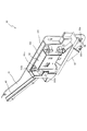
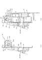
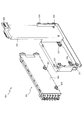
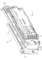
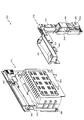
次に、図5から図10を主に参照して内枠ベース30の前面側下部に装着されて内枠13の一部を構成する球発射ユニット90、通路形成部材36、中継基板38について説明する。ここで、図6は球発射ユニット90の正面図であり、図7はその斜視図、図8はその分解斜視図である。又、図9は球送り機構94を構成する開閉部材102を開放した状態における球発射ユニット90の斜視図であり、図10は、図9の状態に対して蓋部材103を取り外し、球送り機構94の内部構成を示した球発射ユニット90の斜視図である。
Next, the ball launch unit 90, the passage forming member 36, and the relay board 38 which are attached to the lower part on the front side of the inner frame base 30 and constitute a part of the inner frame 13 will be described mainly with reference to FIGS. To do. 6 is a front view of the ball launching unit 90, FIG. 7 is a perspective view thereof, and FIG. 8 is an exploded perspective view thereof. 9 is a perspective view of the ball launching unit 90 in a state where the opening / closing member 102 constituting the ball feeding mechanism 94 is opened, and FIG. 10 is a perspective view of the ball feeding mechanism with the lid member 103 removed from the state of FIG. FIG. 9 is a perspective view of a ball launch unit 90 showing the internal configuration of 94.
球発射ユニット90は、内枠ベース30下部の取付面30fにネジにより固定されるベース板91と、ベース板91に取り付けられる発射ソレノイド92と、発射ソレノイド92の一端側において発射ソレノイド92の長手方向に平行に延びるようにしてベース板91に取付固定される断面略M字状の発射レール93と、発射レール93の基端部(発射ソレノイド92側の端部)に1球ずつ遊技球を誘導案内する球送り機構94と、発射レール93の基端部上に載置される遊技球を支持して位置決めするようにベース板91に取り付けられた位置決め部材95(図9参照)とを備えている。
The ball launch unit 90 includes a base plate 91 fixed to the attachment surface 30f at the lower part of the inner frame base 30 with screws, a launch solenoid 92 attached to the base plate 91, and a longitudinal direction of the launch solenoid 92 on one end side of the launch solenoid 92. A launch rail 93 having a substantially M-shaped cross section that is attached and fixed to the base plate 91 so as to extend in parallel with the base plate 91, and guides the game balls one by one to the base end portion (the end portion on the launch solenoid 92 side) of the launch rail 93 A ball feeding mechanism 94 for guiding, and a positioning member 95 (see FIG. 9) attached to the base plate 91 so as to support and position the game ball placed on the base end portion of the firing rail 93 are provided. Yes.
ベース板91は、亜鉛合金などの金属製平板をプレス加工して形成されたものであり、内枠ベース30の取付面30fに密着された状態でネジ96により固定される。図8に示すように、ベース板91には、ネジ96を挿通するための締結孔が穿設され、また、発射ソレノイド92を固定するためのボス91aおよびボルト91bと、発射レール93を固定するためのボス91cとが固定されている。
The base plate 91 is formed by pressing a metal flat plate such as a zinc alloy, and is fixed by screws 96 in a state of being in close contact with the mounting surface 30 f of the inner frame base 30. As shown in FIG. 8, the base plate 91 is provided with a fastening hole for inserting the screw 96, and the boss 91a and the bolt 91b for fixing the firing solenoid 92 and the firing rail 93 are secured. The boss 91c is fixed.
ベース板91の取付位置は、多数のパチンコ機10を製造しても内枠ベース30に対して安定するように高精度が望まれる。遊技盤16との相対位置がパチンコ機10毎に変化すると、それに伴って発射ソレノイド92により発射された遊技球の飛び量が異なるものとなり、操作ハンドルの回動操作に対応する遊技球の飛び量がパチンコ機10毎に不安定となるからである。本実施形態のパチンコ機10においては、ベース板91を従来より大型にして内枠ベース30との相対的な取付位置を安定させている。具体的には、ベース板91の下端は操作ハンドル310の回動軸心(図5のAHで示す位置)より下側まで延ばし、その右端は遊技盤16の右端と略同一となるようにし、その左端は遊技領域の中央を越えるようにアウト口66より左側まで延ばし、その上端は遊技盤16の下端に近接する位置まで延ばしている。また、ベース板91を固定するためのネジ96の数を従来より多く(6つ)している。更に、各ネジ96の締結位置(図5参照)を従来より離間させるようにし、例えば、下側のネジ96の締結位置は操作ハンドル310の回動軸心AHより下側にして取付位置の安定化を図っている。
The mounting position of the base plate 91 is desired to be highly accurate so as to be stable with respect to the inner frame base 30 even when many pachinko machines 10 are manufactured. When the relative position with respect to the game board 16 changes for each pachinko machine 10, the jump amount of the game ball fired by the launch solenoid 92 differs accordingly, and the jump amount of the game ball corresponding to the turning operation of the operation handle This is because each pachinko machine 10 becomes unstable. In the pachinko machine 10 of this embodiment, the base plate 91 is made larger than the conventional one, and the relative mounting position with the inner frame base 30 is stabilized. Specifically, the lower end of the base plate 91 extends below the pivot axis (position indicated by AH in FIG. 5) of the operation handle 310, and the right end thereof is substantially the same as the right end of the game board 16, Its left end extends to the left side from the out port 66 so as to cross the center of the game area, and its upper end extends to a position close to the lower end of the game board 16. Further, the number of screws 96 for fixing the base plate 91 is increased (six) from the conventional one. Further, the fastening position of each screw 96 (see FIG. 5) is separated from the conventional one. For example, the fastening position of the lower screw 96 is below the rotation axis AH of the operation handle 310, and the mounting position is stable. We are trying to make it.
発射レール93は、発射ソレノイド92により発射された直後の遊技球を案内するものであり、所定の発射角度(打ち出し角度)にしつつ直線的に延びるようにしてベース板91に固定されたボス91cにネジ(図示せず)で固定されている。操作ハンドル310の回動操作に伴い発射された遊技球は、まずは発射レール93に沿って斜め上方に打ち出され、その後、前述した通り2本のレール61,62の間に形成される誘導レールを通じて遊技領域に案内される。
The launch rail 93 guides the game ball immediately after being fired by the launch solenoid 92, and extends to a boss 91c fixed to the base plate 91 so as to extend linearly while maintaining a predetermined launch angle (launch angle). It is fixed with screws (not shown). A game ball that is launched in accordance with the turning operation of the operation handle 310 is first launched obliquely upward along the launch rail 93, and then through the guide rail formed between the two rails 61 and 62 as described above. Guided to the game area.
ここで、本パチンコ機10の場合、遊技領域が従来よりも大幅に拡張されることは既に述べたが、かかる構成においては遊技球の発射位置と遊技領域との距離が近づいて発射レールが短くなりがちである。発射レール93が短いと球誘導距離が少なくなって打出球のばらつきが大きくなるので、打出球を安定化させるための工夫を要する。本実施形態では、遊技球の発射位置を低くすると共に発射レール93の傾斜角度(発射角度)を既存のものよりも幾分大きくして(即ち発射レール93を立ち上げるようにし)、発射レール93の長さを約240mmにして十分な長さの球誘導距離を確保している。これにより、発射装置から発射された遊技球をより安定した状態で誘導レールに案内できるようにしている。この場合、特に、発射レール93は、発射ソレノイド92により打撃される遊技球の発射位置から遊技領域の中央位置(アウト口66)を越える位置まで延びるよう形成している。
Here, in the case of this pachinko machine 10, it has already been described that the game area is greatly expanded as compared with the conventional case, but in such a configuration, the distance between the launch position of the game ball and the game area becomes closer and the launch rail becomes shorter. It tends to be. If the launch rail 93 is short, the ball guiding distance is reduced and the variation of the launch ball is increased. Therefore, a device for stabilizing the launch ball is required. In this embodiment, the launch position of the game ball is lowered and the inclination angle (launch angle) of the launch rail 93 is made somewhat larger than that of the existing one (that is, the launch rail 93 is raised). The length of the ball is about 240 mm to ensure a sufficiently long ball guiding distance. Thereby, the game ball launched from the launching device can be guided to the guide rail in a more stable state. In this case, in particular, the launch rail 93 is formed to extend from the launch position of the game ball hit by the launch solenoid 92 to a position beyond the center position (out port 66) of the game area.
また、パチンコ機10においては、遊技球を発射する発射装置として、従来一般的に使用されているモータ及び発射槌の組合せではなく、リニアソレノイドをケース部材に収容した1ユニットのソレノイド(発射ソレノイド)92を採用している。発射ソレノイド92には、発射レール93と長手方向を平行にして配設される金属製のプランジャ92aと、プランジャ92aの先端を覆う樹脂製のキャップ92bとが設けられる。キャップ92bの材質としては本実施形態においてはポリエステル系熱可塑性エラストマーが採用されている。遊技者が操作ハンドル310を回動操作した状態中には、発射ソレノイド92は、所定時間毎に励磁と非励磁とを繰り返して行い、これに対応してプランジャ92aの出没が繰り返される。プランジャ92aが突出したときには、位置決め部材95によって発射レール93上に位置決めされた遊技球は、発射レール93の指向する斜め上方に向けて発射される。なお、操作ハンドル310に連動する可変抵抗器が発射ソレノイド92に結線されており、操作ハンドル310の操作量に基づいてプランジャ92aの突出速度が調整され(ストローク量はほぼ一定)、遊技球の発射速度ひいては飛び量が操作ハンドル310の回動量により調整される。
Further, in the pachinko machine 10, as a launching device for launching a game ball, a single unit solenoid (launch solenoid) in which a linear solenoid is housed in a case member, instead of a combination of a motor and a launching rod that are generally used conventionally. 92 is adopted. The firing solenoid 92 is provided with a metal plunger 92a disposed parallel to the firing rail 93 and a longitudinal direction, and a resin cap 92b covering the tip of the plunger 92a. As the material of the cap 92b, a polyester-based thermoplastic elastomer is employed in the present embodiment. While the player is turning the operation handle 310, the firing solenoid 92 repeats excitation and de-excitation every predetermined time, and the plunger 92a is repeatedly moved up and down accordingly. When the plunger 92 a protrudes, the game ball positioned on the firing rail 93 by the positioning member 95 is launched toward an obliquely upward direction toward the firing rail 93. A variable resistor that is linked to the operation handle 310 is connected to the firing solenoid 92, and the protruding speed of the plunger 92a is adjusted based on the operation amount of the operation handle 310 (the stroke amount is substantially constant). The speed and thus the jump amount is adjusted by the rotation amount of the operation handle 310.
発射ソレノイド92は、図8に示すように、ベース板91に立設される一対のボス91aおよびボルト91bに対して、ボルト97とナット98とを取り付けて固定される。発射ソレノイド92には、ボス91aとボルト91bに対応する位置に、ボルト91b,97が挿通される締結孔92cが設けられている。球発射ユニット90においては、発射ソレノイド92の上下に設けられるボルト97及びナット98の締め具合を調整することによりベース板91に対する発射ソレノイド92の高さを異ならせてプランジャ92aと発射レール93との相対的な取付位置を調整し、遊技球の打点を調整することができるようになっている。パチンコ機10の製造時において各部品の製造上や組み付け上のばらつきがあってもパチンコ機10に球発射ユニット90を組み付けた後にボルト97とナット98とを調整して遊技球の飛び量を微調整することができる。また、発射ソレノイド92は、その全体がベース板9lの外周縁より内側に配設されており、ベース板91側から内枠ベース30に球発射ユニット90を組み付ける際に発射ソレノイド92が他の部品に引っ掛かって破損することが防止されている。
As shown in FIG. 8, the firing solenoid 92 is fixed to a pair of bosses 91a and bolts 91b erected on the base plate 91 by attaching bolts 97 and nuts 98 thereto. The firing solenoid 92 is provided with a fastening hole 92c through which the bolts 91b and 97 are inserted at positions corresponding to the boss 91a and the bolt 91b. In the ball launch unit 90, the height of the launch solenoid 92 relative to the base plate 91 is made different by adjusting the tightening of the bolts 97 and nuts 98 provided above and below the launch solenoid 92, so that the plunger 92a and the launch rail 93 The relative mounting position can be adjusted, and the hitting point of the game ball can be adjusted. Even if there is a variation in manufacturing and assembling of each part at the time of manufacturing the pachinko machine 10, the ball launch unit 90 is assembled to the pachinko machine 10 and then the bolt 97 and the nut 98 are adjusted to reduce the flying amount of the game ball. Can be adjusted. The firing solenoid 92 is entirely disposed inside the outer peripheral edge of the base plate 9l. When the ball launching unit 90 is assembled to the inner frame base 30 from the base plate 91 side, the firing solenoid 92 is another component. It is prevented from being caught and damaged.
位置決め部材95は、発射レール93の右側端部(基端部)上に載置される遊技球を支持して打撃位置に遊技球を位置決めするための部材であり、図9に示すように、ベース板91より発射レール93が設けられる面側に円柱状に突出形成される。位置決め部材95には、その軸方向に沿って貫通する締結孔が設けられ、この締結孔にネジを貫挿することによってベース板91に位置決め部材95は螺着されている。ここで、位置決め部材95の締結孔は、円柱形状の中心ではなく、偏心した位置に形成されている。このため、位置決め部材95を適宜回動させてからネジを締め込むことにより発射レール93上に載置される遊技球の打撃位置を微妙に変更することができ、パチンコ機10の製造時および製造後において簡単に遊技球の飛び量を調整することができる。
The positioning member 95 is a member for supporting the game ball placed on the right end portion (base end portion) of the firing rail 93 and positioning the game ball at the hitting position, as shown in FIG. The base plate 91 is formed so as to protrude in a columnar shape on the surface side on which the firing rail 93 is provided. The positioning member 95 is provided with a fastening hole penetrating along the axial direction, and the positioning member 95 is screwed to the base plate 91 by inserting a screw into the fastening hole. Here, the fastening hole of the positioning member 95 is formed not at the center of the columnar shape but at an eccentric position. For this reason, it is possible to slightly change the hitting position of the game ball placed on the firing rail 93 by rotating the positioning member 95 appropriately and then tightening the screw, and at the time of manufacturing and manufacturing the pachinko machine 10 Later, it is possible to easily adjust the jump amount of the game ball.
球送り機構94は、上皿201から連続して案内されてくる遊技球を1球ずつ、発射レール93の基端部に送るものである。この球送り機構94は、発射ソレノイド92の上部を被覆するようにしてベース板91に固定される樹脂製の台座部材101と、台座部材101の片側(図6の右側)に軸支されて開閉可能に構成された樹脂製の開閉部材102とを備えている。台座部材101には、開閉部材102が設けられる前方側へ向けて係止爪101aが一体的に突出形成され、開閉部材102には、台座部材101の前面に重なる閉鎖状態にて係止爪101aが引っ掛かる係止孔102aが形成されている。開閉部材102は、通常時には、一方側が台座部材101に軸支されると共に他方側が係止孔102aにより台座部材101に係止されて台座部材101の前面に重なって固定された閉鎖状態となる。この閉鎖状態は、台座部材101の係止爪101aを開閉部材102の係止孔102aから外すことにより解除され、開閉部材102は台座部材101に対して前方側へ開放し得る。また、開閉部材102は、台座部材101に対して最大に開放することにより、上側へスライドして台座部材101から取り外し可能となっている。
The ball feeding mechanism 94 feeds the game balls continuously guided from the upper plate 201 one by one to the base end portion of the firing rail 93. The ball feeding mechanism 94 is made of a resin base member 101 fixed to the base plate 91 so as to cover the upper part of the firing solenoid 92, and is pivotally supported on one side (right side in FIG. 6) of the base member 101 to open and close. And a resin opening / closing member 102 configured to be capable of being used. The base member 101 is integrally formed with a locking claw 101a toward the front side where the opening / closing member 102 is provided. The opening / closing member 102 has a locking claw 101a in a closed state overlapping the front surface of the base member 101. A locking hole 102a is formed in which is caught. Normally, the opening / closing member 102 is in a closed state in which one side is pivotally supported by the pedestal member 101 and the other side is locked to the pedestal member 101 by a locking hole 102a and overlaps and is fixed to the front surface of the pedestal member 101. This closed state is released by removing the locking claw 101 a of the base member 101 from the locking hole 102 a of the opening and closing member 102, and the opening and closing member 102 can be opened forward with respect to the base member 101. Further, the opening / closing member 102 can be slid upward to be detached from the pedestal member 101 by opening to the maximum with respect to the pedestal member 101.
台座部材101の下部は、下皿ユニット15と内枠ベース30の取付面30fとの上部隙間を覆いつつ下皿ユニット15の前面側に向けて下降傾斜した形状に形成されている。また、この台座部材101の正面視左側には、通路形成部材36が台座部材101より左側における下皿ユニット15と内枠ベース30の取付面30fとの上部隙間を覆いつつ下皿ユニット15の前面側に向けて下降傾斜した形状に形成されている。このため、前面枠14を開放した場合に球発射ユニット90の部位に遊技球が落下しても下皿ユニット15の背面側には遊技球が入り込まずに前面側に流出するようになっている。
The lower part of the pedestal member 101 is formed in a shape inclined downward toward the front side of the lower dish unit 15 while covering the upper gap between the lower dish unit 15 and the mounting surface 30f of the inner frame base 30. Further, on the left side of the pedestal member 101 when viewed from the front, the passage forming member 36 covers the upper gap between the lower plate unit 15 and the mounting surface 30f of the inner frame base 30 on the left side of the pedestal member 101 and the front surface of the lower plate unit 15. It is formed in a shape that is inclined downward toward the side. For this reason, when the front frame 14 is opened, even if the game ball falls on the part of the ball launching unit 90, the game ball does not enter the back side of the lower dish unit 15 and flows out to the front side. .
開閉部材102の前面には、図6に示すように、正面視左側端部に上皿201から案内されてくる遊技球を導入する導入口102bが設けられており、この導入口102bから遊技球が開閉部材102の裏面側へ導入される。開閉部材102の裏面側には、図9に示すように蓋部材103が着脱可能に取り付けられ、その蓋部材103に電磁石104と送出部材105とが覆われている。電磁石104と送出部材105とは、遊技球を1球ずつ送り出すために動作する部材であり、図10に示すように、開閉部材102に凹設された収容空間に電磁石104を上側にして上下に並んで配置されている。
As shown in FIG. 6, an introduction port 102b for introducing a game ball guided from the upper plate 201 is provided at the front end of the opening / closing member 102 as viewed from the front, and the game ball is introduced from the introduction port 102b. Is introduced to the back side of the opening / closing member 102. As shown in FIG. 9, a lid member 103 is detachably attached to the back surface side of the opening / closing member 102, and the lid magnet 103 covers the electromagnet 104 and the delivery member 105. The electromagnet 104 and the delivery member 105 are members that operate to send out the game balls one by one. As shown in FIG. 10, the electromagnet 104 faces upward in the accommodation space recessed in the opening / closing member 102. They are arranged side by side.
送出部材105は、ピンにより開閉部材102に対して導入口102b側の一辺側が上下に揺動可能に軸支された樹脂製の部材であり、その導入口側の一辺に遊技球が1個だけ収容可能に凹設されたホルダ部105aを備えている。また、ピンが挿通される軸部とホルダ部105aとを結ぶ上辺部分には、電磁石104に対向するようにして金属片106が取り付けられている。
The delivery member 105 is a resin-made member that is pivotally supported by a pin so that one side of the introduction port 102b can swing up and down with respect to the opening / closing member 102, and only one game ball is provided on one side of the introduction port. A holder portion 105a that is recessed so as to be accommodated is provided. A metal piece 106 is attached to the upper side portion connecting the shaft portion through which the pin is inserted and the holder portion 105 a so as to face the electromagnet 104.
電磁石104がオン(励磁)された場合には、金属片106が電磁石104にくっつくように引っ張られ、送出部材105が上方へ回動する。導入口102bから連続して遊技球が導入される場合、先頭の遊技球はホルダ部105aに収容されて上下移動が規制され、後続の遊技球はホルダ部105aに収容された遊技球に支えられて流下が規制される。
When the electromagnet 104 is turned on (excited), the metal piece 106 is pulled so as to stick to the electromagnet 104, and the delivery member 105 rotates upward. When game balls are continuously introduced from the introduction port 102b, the top game ball is accommodated in the holder portion 105a and the vertical movement is restricted, and the subsequent game balls are supported by the game balls accommodated in the holder portion 105a. The flow is regulated.
遊技球がホルダ部105aに収容された状態で電磁石104がオフ(非励磁)となると、送出部材105は自重により下方へ回動し、ホルダ部105aに収容されていた遊技球は下側へ流下する。このとき、後続の遊技球は、送出部材105の上辺によってホルダ部105aへの移行が規制されるため、送出部材105の上下動によりホルダ部105aに収容された1球だけが下方へ送り出される。下方へ送り出された遊技球は、開閉部材102と蓋部材103とにより形成される送出口102c(図9参照)を経由して発射レール93上へと案内される。このため、電磁石104の励磁と非励磁とを繰り返すと、その繰り返しに同期して遊技球は1球ずつ発射レール93上へ案内され、電磁石104のオンオフに同期して発射ソレノイド92を励磁することにより、発射レール93上の遊技球を1球ずつ遊技領域へ向けて発射することができる。
When the electromagnet 104 is turned off (de-energized) in a state where the game ball is accommodated in the holder portion 105a, the delivery member 105 rotates downward by its own weight, and the game ball accommodated in the holder portion 105a flows downward. To do. At this time, since the transition of the subsequent game ball to the holder portion 105 a is restricted by the upper side of the delivery member 105, only one ball accommodated in the holder portion 105 a is sent downward by the vertical movement of the delivery member 105. The game ball delivered downward is guided onto the firing rail 93 via the delivery port 102c (see FIG. 9) formed by the opening / closing member 102 and the lid member 103. Therefore, when the excitation and de-excitation of the electromagnet 104 are repeated, the game balls are guided one by one onto the launch rail 93 in synchronization with the repetition, and the launch solenoid 92 is excited in synchronization with the on / off of the electromagnet 104. Thus, the game balls on the launch rail 93 can be launched one by one toward the game area.
次に、図5を主に参照して内枠13の前面側に設けられる通路形成部材36について説明する。通路形成部材36は、上皿201が満タンのときに遊技球を下皿301へ排出するための下皿排出通路(図示せず)と、ファール球を下皿301へ排出するためのファール球通路(図示せず)とを形成するための部材である。ここで、ファール球とは、発射時の打ち出し力(発射力)が弱くて戻り球防止部材68が位置する遊技領域の入口に到達せずに発射レール93側へ戻った遊技球を意味している。
Next, the passage forming member 36 provided on the front side of the inner frame 13 will be described with reference mainly to FIG. The passage forming member 36 includes a lower tray discharge passage (not shown) for discharging the game balls to the lower plate 301 when the upper plate 201 is full, and a foul ball for discharging the foul balls to the lower plate 301. It is a member for forming a passage (not shown). Here, the foul ball means a game ball that returns to the launch rail 93 side without reaching the entrance of the game area where the return ball prevention member 68 is located because the launch force (launch force) at the time of launch is weak. Yes.
発射レール93と遊技盤16前面のレール(誘導レール)61,62との間には、約40mmの隙間が形成され、この隙間の下側にファール球通路が設けられている。内枠13の前面であって球発射ユニット90の左隣には、透明樹脂製の通路形成部材36がネジにより内枠ベース30の取付面30fに固定される。通路形成部材36には、内枠13の取付面30f側に向いて開口した溝が設けられ、この溝と内枠ベース30の取付面30fとによりファール球通路が形成される。ファール球通路は、途中から上皿201から溢れた遊技球を下皿301へ導く下皿排出通路に合流する。この下皿排出通路の最下流部には、取付面30fより内枠ベース30の前方側に向けて筒状に突出する下皿排出口36aが設けられており、ファール球は、下皿排出通路を経由して下皿排出口36aより下皿301へ排出される。
A gap of about 40 mm is formed between the launch rail 93 and the rails (guidance rails) 61 and 62 on the front surface of the game board 16, and a foul ball passage is provided below the gap. A passage forming member 36 made of a transparent resin is fixed to the mounting surface 30f of the inner frame base 30 with screws on the front surface of the inner frame 13 and on the left side of the ball launch unit 90. The passage forming member 36 is provided with a groove that opens toward the mounting surface 30 f side of the inner frame 13, and a foul ball passage is formed by the groove and the mounting surface 30 f of the inner frame base 30. The foul ball passage joins a lower tray discharge passage that guides game balls overflowing from the upper plate 201 to the lower plate 301 from the middle. A lower tray discharge port 36a that protrudes in a cylindrical shape from the mounting surface 30f toward the front side of the inner frame base 30 is provided at the most downstream portion of the lower tray discharge passage. Is discharged from the lower plate discharge port 36a to the lower plate 301.
排出通路の途中には、下皿301が遊技球で満タンとなっていることを検出するための満タンセンサ(図示せず)が通路底面の一部を形成するように設けられる。遊技球が短期間で多量に払い出されると、上皿201が一杯となった後には下皿301に遊技球が溜まり始める。その後、遊技球が払い出され続けても下皿301の遊技球を抜かないと排出通路の途中に遊技球が溜まり始めるが、満タンセンサの設置箇所まで遊技球が溜まるとそれ以降の払い出しは後述する払出発射制御装置611(図23参照)の制御により停止される。排出通路が満タンになっても遊技球が払い出され続けると、下皿301が溢れて遊技の続行が困難となったり、遊技球を払い出すためのギヤに遊技球が詰まって故障の原因となる等、問題が起こりやすいからである。また、排出通路の満タンが満タンセンサにより検出されると、払出発射制御装置611の制御によって「球を抜いて下さい」のエラーメッセージがスピーカSP(図2参照)より繰り返して出力される。遊技者には、下皿301内に遊技球が溜まったことを示すことができ、下皿301の遊技球を取り出す操作を促すことができる。
In the middle of the discharge passage, a full tank sensor (not shown) for detecting that the lower tray 301 is full of game balls is provided so as to form a part of the passage bottom surface. When a large amount of game balls are paid out in a short period of time, game balls start to accumulate in the lower plate 301 after the upper plate 201 is full. After that, even if the game balls continue to be paid out, if the game balls on the lower plate 301 are not pulled out, the game balls will start to collect in the discharge passage. It is stopped by the control of the payout and emission control device 611 (see FIG. 23). If the game ball continues to be paid out even if the discharge passage is full, the lower plate 301 overflows and it becomes difficult to continue the game, or the game ball gets stuck in the gear for paying out the game ball This is because problems are likely to occur. When the full tank of the discharge passage is detected by the full tank sensor, an error message “please remove the ball” is repeatedly output from the speaker SP (see FIG. 2) under the control of the payout launch control device 611. The player can be shown that the game balls have accumulated in the lower plate 301, and can be prompted to take out the game balls from the lower plate 301.
通路形成部材36の左上部には、上皿201に遊技球を排出するための上皿排出口36bが設けられ、内枠ベース30には、その上皿排出口36bへ遊技球を払い出すための払出口が設けられている。内枠ベース30の払出口は、内枠ベース30の裏面と前面とを結ぶものであり、内枠13の裏面側に設けられる払出装置658(図20参照)に繋げられている。払出口および上皿排出口36bは前面枠14を閉鎖した状態において上皿201に通じており、払出口および上皿排出口36bを介して上皿201に遊技球が排出される(払い出される)。上皿排出口36bには、開閉式のシャッタ37が取り付けられており、前面枠14を開放した状態(図2の状態)ではバネ等の付勢力によりシャッタ37は上皿排出口36bを閉鎖する。また、前面枠14を閉鎖した状態では、当該前面枠14の裏面に設けられた球通路樋241(図2参照)によりシャッタ37は内枠ベース30側へ傾倒して押し開けられる。従って、前飾り枠が省略され前面枠14に上皿201が直接設けられる構成とした本パチンコ機10において、前面枠14の開放に際し内枠ベース30の払出口を通過中の遊技球が内枠13の前面にこぼれ落ちてしまうといった不都合が防止できるようになっている。
An upper tray discharge port 36b for discharging game balls to the upper plate 201 is provided in the upper left part of the passage forming member 36, and the inner frame base 30 is used for paying out game balls to the upper plate discharge port 36b. There is a payout exit. The payout port of the inner frame base 30 connects the back surface and the front surface of the inner frame base 30 and is connected to a payout device 658 (see FIG. 20) provided on the back surface side of the inner frame 13. The payout opening and the upper tray discharge port 36b communicate with the upper plate 201 in a state in which the front frame 14 is closed, and the game ball is discharged (paid out) to the upper plate 201 through the discharge port and the upper plate discharge port 36b. . An open / close shutter 37 is attached to the upper plate discharge port 36b. When the front frame 14 is opened (the state shown in FIG. 2), the shutter 37 closes the upper plate discharge port 36b by an urging force such as a spring. . When the front frame 14 is closed, the shutter 37 is tilted toward the inner frame base 30 and pushed open by a ball passage rod 241 (see FIG. 2) provided on the back surface of the front frame 14. Therefore, in the present pachinko machine 10 in which the front decorative frame is omitted and the upper plate 201 is directly provided on the front frame 14, the game ball passing through the payout opening of the inner frame base 30 is opened when the front frame 14 is opened. Inconveniences such as spilling down on the front surface of 13 can be prevented.
通路形成部材36における下皿排出口36aの下側は、内枠13の下面に当接する長さのリブ36cが設けられており、平板状に形成された内枠ベース30の取付面30fが補強されている。また、リブ36cと取付面30fとの間には配線を通す隙間が設けられ、電気配線のホルダとしてリブ36cが活用されている。
On the lower side of the lower plate discharge port 36a in the passage forming member 36, a rib 36c having a length contacting the lower surface of the inner frame 13 is provided, and the mounting surface 30f of the inner frame base 30 formed in a flat plate shape is reinforced. Has been. Further, a gap through which the wiring passes is provided between the rib 36c and the mounting surface 30f, and the rib 36c is used as a holder for electric wiring.
内枠ベース30の前面左下隅には、中継基板38が収容されている。中継基板38には、下皿ユニット15に設けられる電気部品(操作ハンドル310内部のタッチセンサ及び可変抵抗器、並びに、スピーカSP)の配線と、内枠13側に設けられる制御装置(払出発射制御装置611および音声ランプ制御装置562)とを接続する部位であり、下皿ユニット13側の配線コード先端に設けられるコネクタに連結する差込口(図示せず)が設けられる。下皿ユニット15と内枠13との電気的な接続が中継基板38にまとめられているため、下皿ユニット15の組み付け及び取り外し時における配線の取り回し作業が簡易になり、パチンコ機10の組み立て及び分解が容易になっている。また、中継基板38には、スピーカSPの音量を大小2段階に調節するスイッチが設けられ、内枠13を開放しなくても簡単に音量調節を実行することができる。なお、中継基板38から内枠13の裏面側に設けられる制御装置への配線は、内枠ベース30の取付面30fの下端に沿って、また通路形成部材36のリブ36cの奥側に配置され、内枠ベース30の前面右下隅に開口形成された配線穴30hより内枠13の裏面に取り回されている。
A relay board 38 is accommodated in the lower left corner of the front surface of the inner frame base 30. On the relay board 38, wiring of electrical components (touch sensor and variable resistor inside the operation handle 310 and the speaker SP) provided in the lower tray unit 15 and a control device (payout launch control) provided on the inner frame 13 side are provided. It is a part which connects the apparatus 611 and the audio | voice lamp control apparatus 562), and the insertion port (not shown) connected with the connector provided in the wiring cord front end by the side of the lower pan unit 13 is provided. Since the electrical connection between the lower tray unit 15 and the inner frame 13 is gathered on the relay substrate 38, the wiring work when assembling and removing the lower tray unit 15 is simplified, and the pachinko machine 10 is assembled and removed. Disassembly is easy. In addition, the relay board 38 is provided with a switch for adjusting the volume of the speaker SP in two levels, and the volume can be easily adjusted without opening the inner frame 13. The wiring from the relay board 38 to the control device provided on the back side of the inner frame 13 is arranged along the lower end of the mounting surface 30f of the inner frame base 30 and on the inner side of the rib 36c of the passage forming member 36. The inner frame base 30 is routed around the back surface of the inner frame 13 through a wiring hole 30 h formed in the lower right front corner of the front surface.
次に、図1、図2、図11および図12を参照して前面枠14の構成について説明する。図11(a)は前面枠14の背面図であり、図11(b)は図11(a)のR−R線における断面図である。また、図12は球発射ユニット90へ遊技球を送出する上皿201の出口部を断面視して示した図であり、図12(a)は前面枠14が開放された状態を示し、図12(b)は前面枠が閉鎖された状態を示している。
Next, the configuration of the front frame 14 will be described with reference to FIGS. 1, 2, 11, and 12. FIG. 11A is a rear view of the front frame 14, and FIG. 11B is a cross-sectional view taken along the line RR in FIG. 11A. FIG. 12 is a cross-sectional view of the outlet portion of the upper plate 201 that sends out the game ball to the ball launching unit 90. FIG. 12 (b) shows a state in which the front frame is closed.
前面枠14は、矩形状に形成されたABS樹脂製の前面枠ベース200を主体に構成されており、前面枠ベース30の中央部には遊技領域のほとんどを外部から視認することができるよう略楕円形状に開口形成された窓部14cが設けられている。また、窓部14cの下側には、図1に示すように、球受皿としての上皿201が一体的に設けられている。上皿201は、遊技球を一旦貯留し、一列に整列させながら球発射ユニット90へ導出するものである。従来のパチンコ機では前面枠の下方において内枠に対し開閉可能な前飾り枠が設けられ、該前飾り枠に上皿が設けられていたが、本実施形態では前飾り枠が省略され、前面枠14に直接上皿201が設けられている。これは、本実施形態の前面枠14は、従来のパチンコ機より大きく形成した遊技領域を外部から視認できるように略楕円形状に大きく欠成された窓部14cを備えているので、前面枠14の強度を少しでも向上させるべく、該前面枠14に上皿201を一体化して形成しているのである。この上皿201は下皿301と同様に、少なくとも表面層が難燃性のABS樹脂にて形成されている。
The front frame 14 is mainly configured by a front frame base 200 made of ABS resin formed in a rectangular shape, and the front frame base 30 has a central portion so that most of the game area can be visually recognized from the outside. A window portion 14c having an elliptical opening is provided. Moreover, as shown in FIG. 1, the upper plate | board 201 as a ball receiving tray is integrally provided under the window part 14c. The upper plate 201 temporarily stores the game balls and guides them to the ball launch unit 90 while aligning them in a row. In the conventional pachinko machine, a front decorative frame that can be opened and closed with respect to the inner frame is provided below the front frame, and an upper plate is provided on the front decorative frame, but in this embodiment, the front decorative frame is omitted, An upper plate 201 is provided directly on the frame 14. This is because the front frame 14 of the present embodiment includes a window portion 14c that is largely oval shaped so that a game area formed larger than a conventional pachinko machine can be visually recognized from the outside. The upper plate 201 is integrally formed with the front frame 14 in order to improve the strength of the plate as much as possible. Similar to the lower plate 301, the upper plate 201 has at least a surface layer formed of a flame-retardant ABS resin.
前面枠14の窓部14cは、その左右側の略中央部が、上下側に比べて比較的緩やかに湾曲して縦長の楕円形状となっている。窓部14cを形成する前面枠ベース30は、上下方向の方が左右方向より長く形成されているので、窓部14cを大きく開口しつつ前面枠ベース200の上下および左右にて壊れやすい細幅となる部分を比較的広く設けることができ、強度を確保し易くしている。なお、窓部14cの左右側の略中央部を湾曲させないで直線状に形成してもよい。
The window portion 14c of the front frame 14 has a vertically elongated elliptical shape in which a substantially central portion on the left and right sides thereof is curved relatively gently as compared with the upper and lower sides. Since the front frame base 30 forming the window portion 14c is longer in the vertical direction than in the horizontal direction, the front frame base 30 has a narrow width that is easily broken at the top, bottom, left and right of the front frame base 200 while opening the window portion 14c. The part which becomes can be provided comparatively widely, and it is easy to ensure intensity | strength. In addition, you may form in the linear form, without curving the substantially center part of the left-right side of the window part 14c.
本実施形態において、窓部14cの開口上端は、外レール62の最上部(遊技領域の上端)に一致し、その開口上端と前面枠14の上端との間の最短距離(いわゆる上部フレーム部分の上下幅)は約50mmとなっている。85mm〜95mm程度上部フレーム幅がある従来技術に比べて著しく短くなっており、遊技領域の上部領域を確保し易くすると共に、大型の可変表示装置ユニット80を比較的上方に配置することができる。なお、前面枠14の上端との間の距離は80mm以下であることが望ましく、より望ましくは70mm以下であり、更に望ましくは60mm以下である。もちろん、所定の強度が確保できるのであれば、50mm以下であっても差し支えない。
In the present embodiment, the upper end of the opening of the window portion 14c coincides with the uppermost portion of the outer rail 62 (the upper end of the game area), and the shortest distance between the upper end of the opening and the upper end of the front frame 14 (the so-called upper frame portion). The vertical width is about 50 mm. Compared to the prior art having an upper frame width of about 85 mm to 95 mm, the upper frame width is remarkably shortened, so that it is easy to secure the upper area of the game area and the large variable display device unit 80 can be disposed relatively upward. The distance from the upper end of the front frame 14 is desirably 80 mm or less, more desirably 70 mm or less, and further desirably 60 mm or less. Of course, as long as a predetermined strength can be ensured, it may be 50 mm or less.
また、パチンコ機10の正面から見て窓部14cの左端と前面枠14の左端との間の最短距離(いわゆる左側部フレーム部分の左右幅:図11(a)では右側に示される)、即ち開閉軸線側のフレーム幅は、前面枠14自体の強度及び支持強度を高めるために比較的大きく設定されている。前面枠14が閉じられた状態において、外レール62の左端部が前面枠ベース200左側のフレーム部分によって覆い隠されるように、開閉軸線側のフレーム幅が広く設定されている。このため、外レール62は、パチンコ機10の正面からみて前面枠14の左側部フレーム部分と重複して覆い隠され、遊技領域の入口手前における遊技球が視認困難となる。ここで、遊技者は、遊技領域内において種々の挙動を示す遊技球を視認して弾球遊技を楽しむものであるため、遊技領域に入る前の遊技球が視認困難であっても実際の遊技に何ら支障は生じない。よって、遊技に支障を来すことなく、前面枠14の十分な強度及び支持強度を確保することができる。ちなみに、パチンコ機10の正面から見て外レール62の左端位置と外枠12の左端位置との左右方向の距離は約30mm、遊技領域の右端位置(円弧部材70の内面右端位置)と外枠12の右端位置との左右方向の距離は約45mmとなっている。
Further, the shortest distance between the left end of the window portion 14c and the left end of the front frame 14 when viewed from the front of the pachinko machine 10 (the left-right width of the so-called left side frame portion: shown on the right side in FIG. 11 (a)), The frame width on the opening / closing axis side is set to be relatively large in order to increase the strength and support strength of the front frame 14 itself. In the state where the front frame 14 is closed, the frame width on the opening / closing axis side is set wide so that the left end portion of the outer rail 62 is covered and hidden by the frame portion on the left side of the front frame base 200. For this reason, the outer rail 62 is overlapped with the left side frame portion of the front frame 14 when viewed from the front of the pachinko machine 10, and it is difficult to visually recognize the game ball in front of the entrance of the game area. Here, since the player visually recognizes the game balls showing various behaviors in the game area and enjoys the ball game, even if it is difficult to visually recognize the game ball before entering the game area, there is nothing in the actual game. There will be no hindrance. Therefore, sufficient strength and support strength of the front frame 14 can be ensured without hindering the game. Incidentally, the distance in the left-right direction between the left end position of the outer rail 62 and the left end position of the outer frame 12 when viewed from the front of the pachinko machine 10 is about 30 mm, the right end position of the game area (the inner right end position of the arc member 70) and the outer frame. The distance in the left-right direction with respect to the right end position of 12 is about 45 mm.
加えて、前面枠14には、その周囲(例えばコーナー部分)に各種ランプ等の発光手段が設けられている。これら発光手段は、大当たり時や所定のリーチ時等における遊技状態の変化に応じて、点灯又は点滅することにより発光態様が変更制御され、遊技中の演出効果を高める役割を果たす。図1に示すように、窓部14cの上側およびその左右両側には、窓部14cの周縁に沿って、LED等の発光手段を内蔵した電飾部202〜204が設けられている。パチンコ機10においては、これら電飾部202〜204が大当たりランプ等の演出ランプとして機能し、大当たり時やリーチ演出時等には内蔵するLEDの点灯や点滅によって各電飾部202〜204が点灯または点滅して、大当たり中である旨、或いは大当たり一歩手前のリーチ中である旨が報知される。
In addition, the front frame 14 is provided with light emitting means such as various lamps around the periphery (for example, a corner portion). These light-emitting means play a role of enhancing the effect of the game during the game by changing or controlling the light-emitting mode by turning on or flashing according to the change in the gaming state at the time of big hit or predetermined reach. As shown in FIG. 1, on the upper side of the window portion 14c and on both the left and right sides thereof, there are provided electric decoration portions 202 to 204 having built-in light emitting means such as LEDs along the periphery of the window portion 14c. In the pachinko machine 10, these illumination parts 202 to 204 function as effect lamps such as jackpot lamps, and each of the illumination parts 202 to 204 is turned on by lighting or blinking of the built-in LEDs at the time of jackpot or reach effect. Alternatively, it blinks to notify that the jackpot is being hit or that the reach is one step before the jackpot.
また、前面枠14の正面視右上部には、図1に示すように、賞球の払い出し中に点灯する賞球ランプ205が設けられ、一方、前面枠14の正面視左上部には所定のエラー時に点灯するエラー表示ランプ206が設けられている。また、右側の電飾部204の下側には、前面枠14の裏面側を視認できるように前面枠ベース200の裏面側より透明樹脂を取り付けて小窓207が形成され、遊技盤16前面の貼着スペースK1(図3参照)に貼付される証紙等はパチンコ機10の前面から視認可能とされている。また、パチンコ機10においては、より煌びやかさを醸し出すために、電飾部202〜204の周りの領域にクロムメッキを施したABS樹脂製のメッキ部材208が取り付けられている。このクロムメッキには、従来多用されていた6価クロムではなく、生産環境面等を考慮して3価クロムが使用されている。
Further, as shown in FIG. 1, a prize ball lamp 205 that is turned on while awarding a prize ball is provided in the upper right part of the front frame 14 as viewed from the front. An error display lamp 206 that is turned on when an error occurs is provided. In addition, a small window 207 is formed on the lower side of the right illumination part 204 by attaching a transparent resin from the back side of the front frame base 200 so that the back side of the front frame 14 can be seen. A stamp or the like affixed to the affixing space K1 (see FIG. 3) is visible from the front surface of the pachinko machine 10. In addition, in the pachinko machine 10, a plated member 208 made of ABS resin that is chrome-plated is attached to an area around the electric decoration parts 202 to 204 in order to bring out more gorgeousness. For this chrome plating, trivalent chrome is used in consideration of the production environment and the like, instead of hexavalent chrome which has been widely used conventionally.
窓部14cの下方には、図1に示すように、貸球操作部210が配設されている。貸球操作部210には、度数表示部211と、球貸しボタン212と、返却ボタン213とが設けられている。パチンコ機10の側方に配置されるカードユニット(球貸しユニット)(図示せず)に紙幣やカード等を投入した状態で貸球操作部210が操作されると、その操作に応じて遊技球の貸出が行われる。具体的には、度数表示部211はカード等の残額情報が表示される領域であり、内蔵されたLEDが点灯して残額情報として残額が数字で表示される。球貸しボタン212は、カード等(記録媒体)に記録された情報に基づいて貸出球を得るために操作されるものであり、カード等に残額が存在する限りにおいて貸出球が上皿201に供給される。返却ボタン213は、カードユニットに挿入されたカード等の返却を求める際に操作される。なお、カードユニットを介さずに球貸し装置等から上皿に遊技球が直接貸し出されるパチンコ機、いわゆる現金機では貸球操作部210が不要となるが、この場合には、貸球操作部210の設置部分に飾りシール等を付加して部品構成は共通のものとしても良い。カードユニットを用いたパチンコ機と現金機との共通化を図ることができる。
As shown in FIG. 1, a lending operation unit 210 is disposed below the window 14c. The ball lending operation unit 210 is provided with a frequency display unit 211, a ball lending button 212, and a return button 213. When the lending operation unit 210 is operated in a state where a bill or a card is inserted into a card unit (ball lending unit) (not shown) arranged on the side of the pachinko machine 10, a game ball according to the operation Is lent out. Specifically, the frequency display unit 211 is an area in which remaining amount information such as a card is displayed, and a built-in LED is lit to display the remaining amount as a remaining amount information. The ball lending button 212 is operated to obtain a lending ball based on information recorded on a card or the like (recording medium), and the lending ball is supplied to the upper plate 201 as long as there is a remaining amount on the card or the like. Is done. The return button 213 is operated when requesting the return of a card or the like inserted into the card unit. A pachinko machine in which game balls are lent directly to the upper plate from a ball lending device or the like without using a card unit, that is, a so-called cash machine, does not require the ball lending operation unit 210. It is also possible to add a decorative seal or the like to the installation portion of the parts so that the component configuration is common. A pachinko machine using a card unit and a cash machine can be shared.
前面枠14の裏側における右上隅には、図11(a)に示すように、発光手段としてのLED用の発光基板214が前面枠ベース200の裏面にネジにより取り付けられている。また、前面枠14の裏側には、窓部14cを囲むようにして金属製の各種補強部材が設けられている。詳しくは、前面枠14の裏側にあって窓部14cの上下左右の外側には金属製の補強板221〜224がそれぞれ取り付けられている。これら補強板221〜224は相互に接触して連結されて、窓部14cの形成によって低下した前面枠14の剛性および強度を高めている。また、右側の補強板221は、前記した発光基板214の裏面側に重なって配設されているが、両者の直接の接触を避けるように、或いは、発光基板214への通電を防止するために、透明な合成樹脂製のカバー板215が補強板221と発光基板214との間に介在して設けられている。補強板221〜224の帯電に基づいてその周りにノイズや磁界が発生しても、カバー板215の介在によって発光基板214への影響が低減され、誤作動や故障等の抑制が図られている。なお、補強板221〜224の一部は接地されており(図示せず)、補強板221〜224が帯電し難いようになっている。
In the upper right corner on the back side of the front frame 14, as shown in FIG. 11A, a light emitting substrate 214 for LED as a light emitting means is attached to the back surface of the front frame base 200 with screws. In addition, various reinforcing members made of metal are provided on the back side of the front frame 14 so as to surround the window portion 14c. Specifically, metal reinforcing plates 221 to 224 are respectively attached to the back side of the front frame 14 and on the upper and lower and left and right outsides of the window portion 14c. These reinforcing plates 221 to 224 are connected in contact with each other to increase the rigidity and strength of the front frame 14 that has been reduced by the formation of the window portion 14c. Further, the right reinforcing plate 221 is disposed so as to overlap the back side of the light emitting substrate 214 described above, but in order to avoid direct contact between the two, or to prevent the light emitting substrate 214 from being energized. A transparent synthetic resin cover plate 215 is provided between the reinforcing plate 221 and the light emitting substrate 214. Even if a noise or a magnetic field is generated around the reinforcing plates 221 to 224 due to charging, the influence on the light emitting substrate 214 is reduced by the cover plate 215, and malfunctions and failures are suppressed. . A part of the reinforcing plates 221 to 224 is grounded (not shown) so that the reinforcing plates 221 to 224 are not easily charged.
前面枠14の裏面右側の補強板221には、その中間位置にてフック(鉤)状をなす係合爪221a(図2参照)が設けられている。係合爪221aは、前面枠14を閉じた状態で内枠13(内枠ベース30)に穿設された溝30jに進入するように構成されている。内枠ベース30には、図5に示すように、その溝30jの一部を覆うようにして金属製の止め板39がネジ止めされており、内枠13に対して前面枠14が閉鎖された状態において係合爪221aの先端部が図5に示す止め板39の裏面側に入り込む。これにより、パチンコ機10正面視左側の中間位置における前面枠14の浮き上がりを防止することができ、上皿201が前面枠14に設けられて前面枠14が上下に大きく構成され、上下の支持位置(支持金具33,34の位置)が大きく離間しても、前面枠14を浮かしての不正行為を抑制することができる。
The reinforcing plate 221 on the right side of the back surface of the front frame 14 is provided with an engaging claw 221a (see FIG. 2) having a hook shape at an intermediate position. The engaging claw 221a is configured to enter a groove 30j formed in the inner frame 13 (inner frame base 30) with the front frame 14 closed. As shown in FIG. 5, a metal stop plate 39 is screwed to the inner frame base 30 so as to cover a part of the groove 30 j, and the front frame 14 is closed with respect to the inner frame 13. In this state, the tip of the engaging claw 221a enters the back side of the retaining plate 39 shown in FIG. Accordingly, the front frame 14 can be prevented from being lifted at an intermediate position on the left side when viewed from the front of the pachinko machine 10, the upper plate 201 is provided on the front frame 14, and the front frame 14 is configured to be large in the vertical direction. Even if the (positions of the support brackets 33 and 34) are largely separated from each other, an illegal act with the front frame 14 floating can be suppressed.
前面枠14の裏面左側の補強板222には、前面枠14の背面側に突出して鉤状に形成された上下一対の前面枠鉤部14aが一体的に形成されている。この前面枠鉤部14aが内枠13の裏面側に設けられる施錠ユニット410の前面枠用鉤部材411に係合して、前面枠14は施錠される。施錠状態の前面枠14は、シリンダ錠420に対して専用鍵による所定の解錠操作が行われることにより解錠され、開放可能な状態となる。
On the reinforcing plate 222 on the left side of the rear surface of the front frame 14, a pair of upper and lower front frame flange portions 14 a that protrude from the rear surface side of the front frame 14 and are formed in a bowl shape are integrally formed. The front frame 14 is locked by engaging the front frame collar 14 a with the front frame collar 411 of the locking unit 410 provided on the back side of the inner frame 13. The front frame 14 in the locked state is unlocked by performing a predetermined unlocking operation on the cylinder lock 420 with a dedicated key, and is in a state where it can be opened.
前面枠14の裏面上側の補強板223の左右方向における中央部分には、ネジ225を挿通するネジ孔が設けられており、このネジ225の先端部は、図11(b)に示すように、前面枠14の前面側に設けられるメッキ部材208に螺着されており、メッキ部材208はネジ225と補強板223とを通じて接地された状態となる。よって、装飾用のメッキを前面枠14の前面側に施しても帯電およびこれに起因するノイズ等による不具合を抑制することができる。
A screw hole through which the screw 225 is inserted is provided in a central portion in the left-right direction of the reinforcing plate 223 on the upper back side of the front frame 14, and a tip portion of the screw 225 is formed as shown in FIG. It is screwed to a plating member 208 provided on the front side of the front frame 14, and the plating member 208 is grounded through a screw 225 and a reinforcing plate 223. Therefore, even if the decorative plating is applied to the front side of the front frame 14, problems due to charging and noise caused by the charging can be suppressed.
前面枠14の裏面下側の補強板224には、図2に示すように、前記発射レール93に対向する位置に樹脂製のレール側壁部材226が設けられている。このレール側壁部材226は、前面枠14を閉じた際に発射レール93の側壁となって、発射レール93から遊技球がこぼれ落ちないように機能している。また、レール側壁部材226の右側には、上皿201に繋がる穴に連続するようにして前面枠14の裏面側に突出する球通路樋241が前面枠ベース200にネジで固定されている。この球通路樋241は、前面枠14の閉鎖時に内枠13側のシャッタ37(図2参照)を押し開けて上皿201への遊技球の流路を形成する。
As shown in FIG. 2, a resin-made rail side wall member 226 is provided on the reinforcing plate 224 below the back surface of the front frame 14 at a position facing the firing rail 93. The rail side wall member 226 serves as a side wall of the launch rail 93 when the front frame 14 is closed, and functions so that game balls do not spill from the launch rail 93. Further, on the right side of the rail side wall member 226, a ball passage rod 241 that protrudes from the back surface side of the front frame 14 so as to be continuous with the hole connected to the upper plate 201 is fixed to the front frame base 200 with a screw. When the front frame 14 is closed, the ball passage rod 241 pushes the shutter 37 (see FIG. 2) on the inner frame 13 side to form a game ball flow path to the upper plate 201.
前面枠14の裏面側においてレール側壁部材226の左隣には、図11(a)に示すように、下側の補強板224の一部を正方形状に開口して形成された球出口224aが設けられると共に、その球出口224aを前面枠14の開放時に閉鎖するための開閉ユニット230が球出口224aの上側に取り付けられている。球出口224aは、上皿201の最下流部に設けられ、前面枠14の閉鎖時に上皿201と球発射ユニット90の導入口102b(図7参照)とを連通する。上皿201に載置された遊技球は球出口224aを経由して球発射ユニット90の導入口102bへ導かれる。
On the back side of the front frame 14, on the left side of the rail side wall member 226, as shown in FIG. An opening / closing unit 230 is provided on the upper side of the ball outlet 224a. The opening / closing unit 230 closes the ball outlet 224a when the front frame 14 is opened. The ball outlet 224a is provided in the most downstream portion of the upper plate 201, and communicates the upper plate 201 and the introduction port 102b (see FIG. 7) of the ball launch unit 90 when the front frame 14 is closed. The game ball placed on the upper plate 201 is guided to the introduction port 102b of the ball launching unit 90 via the ball outlet 224a.
ここで、図11(a)および図12を参照して開閉ユニット230の構造について説明する。開閉ユニット230は、下側の補強板224にネジ止めされたケース部材としてのハウジング231と、上端がハウジング231内に収容され、それ以外の部分が下側の補強板224に沿うように下方に延びる薄板状の遮蔽板232と、遮蔽板232の上端部が巻回固定されると共にハウジング231の内面にて上下方向に回動可能に軸支された硬質樹脂製の回動レバー233とを備えている。この開閉ユニット230は、ハウジング231に、遮蔽板232、及び、回動レバー233を組み付けて一体化したものであり、前面枠14側への組み付け作業の容易化および簡素化が図られている。
Here, the structure of the opening / closing unit 230 will be described with reference to FIG. The opening / closing unit 230 includes a housing 231 as a case member screwed to the lower reinforcing plate 224, and an upper end accommodated in the housing 231 and a lower portion extending along the lower reinforcing plate 224. A thin plate-shaped shielding plate 232 that extends and a rotation lever 233 made of a hard resin that is rotatably fixed to the inner surface of the housing 231 while the upper end of the shielding plate 232 is wound and fixed. ing. The opening / closing unit 230 is integrated with the housing 231 by assembling the shielding plate 232 and the rotation lever 233, and the assembling work on the front frame 14 side is facilitated and simplified.
回動レバー233は、下側の補強板224と略平行かつ略水平にハウジング231内面に設けられる回動軸231aを軸心としてハウジング231に回動可能に軸支される。回動レバー233には、回動軸231aより補強板224側(図12(a)の左側)に向けて延設される板支持部233aと、回動軸231aより下側に向かって延設され、前面枠14の閉鎖時に内枠13の一部に当接するようにハウジング231外に突出する接触部233bとが設けられる。内枠ベース30には、取付面30fより前面に突出形成された突起30k(図5参照)が設けられ、接触部233bは、突起30kに当接するように設けられる。この接触部233bは、回動軸231aに対して前面枠14の開閉方向(図12(a)の左右方向)とほぼ直行する方向に延設されているため、前面枠14の閉鎖時に接触部233bが内枠13に押圧された場合に回動レバー233が回動し易く、長期の使用にわたっての動作を確実なものとしている。
The rotation lever 233 is pivotally supported by the housing 231 about a rotation shaft 231a provided on the inner surface of the housing 231 so as to be substantially parallel and substantially horizontal to the lower reinforcing plate 224. The rotation lever 233 includes a plate support portion 233a extending from the rotation shaft 231a toward the reinforcing plate 224 (left side in FIG. 12A), and extending downward from the rotation shaft 231a. In addition, a contact portion 233b that protrudes out of the housing 231 is provided so as to abut a part of the inner frame 13 when the front frame 14 is closed. The inner frame base 30 is provided with a protrusion 30k (see FIG. 5) that protrudes from the attachment surface 30f to the front surface, and the contact portion 233b is provided so as to contact the protrusion 30k. Since the contact portion 233b extends in a direction substantially perpendicular to the opening / closing direction of the front frame 14 (the left-right direction in FIG. 12A) with respect to the rotation shaft 231a, the contact portion is closed when the front frame 14 is closed. When the 233b is pressed by the inner frame 13, the rotation lever 233 is easy to rotate, and the operation over a long period of time is ensured.
遮蔽板232は、弾性を有する薄板状の金属片(例えば、ステンレス薄板など)で形成され、一端が回動レバー233の板支持部233a(前面枠14側の端部)に固定される一方、他端である下端部232aは自由端となっている。遮蔽板232の下端部232aは、図11(a)に示すように、球出口224aより幅広く形成されている。このため、遮蔽板232の途中部分における弾性変形を容易にして動作抵抗を低くしつつも、遮蔽板232の下端部232aによって球出口224aを確実に覆って球出口224aからの遊技球の流出を遮蔽板232により確実に阻止することができる。なお、下端部232aの幅は、球出口224aより細くても良いが、ほぼ同一以上の幅とすることが遊技球の誤流出を防止する上で好ましく、球出口224aより遮蔽板232の下端部232aの幅を広くすることが好適である。
The shielding plate 232 is formed of an elastic thin plate-like metal piece (for example, a stainless steel thin plate), and one end is fixed to the plate support portion 233a (the end portion on the front frame 14 side) of the rotating lever 233, The lower end 232a which is the other end is a free end. The lower end 232a of the shielding plate 232 is formed wider than the ball outlet 224a as shown in FIG. Therefore, the ball outlet 224a is reliably covered by the lower end portion 232a of the shielding plate 232 so that the elastic deformation in the middle portion of the shielding plate 232 is facilitated and the operation resistance is lowered, so that the game ball flows out of the ball outlet 224a. The shielding plate 232 can surely prevent it. Note that the width of the lower end 232a may be narrower than the ball outlet 224a, but it is preferable to set the width to be equal to or greater than the same in order to prevent an erroneous outflow of the game ball, and the lower end of the shielding plate 232 from the ball outlet 224a. It is preferable to widen the width of 232a.
また、遮蔽板232の下端部232aが球出口224aより狭いと、球出口224a内に遮蔽板232が入り込んで球出口224a内の遊技球に遮蔽板232の下端が衝突し、遮蔽板232の変形や破損が生じ易い。パチンコ機10においては、遮蔽板232の下端部232aが球出口224aより広幅とされているので、球出口224a内に遮蔽板232が入り込むことがなく、遊技球への当接による遮蔽板232の変形や破損が防止されている。
If the lower end 232a of the shielding plate 232 is narrower than the ball outlet 224a, the shielding plate 232 enters the ball outlet 224a, the lower end of the shielding plate 232 collides with the game ball in the ball outlet 224a, and the shielding plate 232 is deformed. And damage is likely to occur. In the pachinko machine 10, the lower end portion 232a of the shielding plate 232 is wider than the ball outlet 224a. Deformation and damage are prevented.
ここで、球出口224aの下側には、図12(a)に示すように、上皿201から下皿301へ通じる通路と、その通路を閉鎖する閉鎖板234とが設けられ、その閉鎖板234がパチンコ機10の前面側(図12(a)の左側)へ移動可能となっている。閉鎖板234が前面側へ移動すると上皿201と下皿301とが連通し、遊技球が下皿301へ流下する。この場合に球出口224aより遮蔽板232の下端部232aが幅狭であると、その下端部232aが球出口224a内に入り込んで球詰まりが生じうる。遮蔽板232の下端部232aを球出口224aより幅広に形成することで上皿201と下皿301との連通を確実にすることができ、球詰まりの発生を抑制することできる。
Here, on the lower side of the ball outlet 224a, as shown in FIG. 12 (a), a passage leading from the upper plate 201 to the lower plate 301 and a closing plate 234 for closing the passage are provided. 234 is movable to the front side of the pachinko machine 10 (left side in FIG. 12A). When the closing plate 234 moves to the front side, the upper plate 201 and the lower plate 301 communicate with each other, and the game ball flows down to the lower plate 301. In this case, if the lower end portion 232a of the shielding plate 232 is narrower than the bulb outlet 224a, the lower end portion 232a may enter the bulb outlet 224a to cause clogging. By forming the lower end 232a of the shielding plate 232 wider than the bulb outlet 224a, the communication between the upper plate 201 and the lower plate 301 can be ensured, and the occurrence of clogging of the bulb can be suppressed.
開閉ユニット230の遮蔽板232は、平面状の薄板を下方に弾性変形させて曲折させた状態にして、補強板224と回動レバー233の板支持部233aとに支持されている。このため、遮蔽板232は、弾性力により元の平らな状態に復帰しようとして補強板224を押圧した状態となっている。前面枠14fの開状態(図12(a)の状態)にあっては、球出口224aが遮蔽板232に押圧されつつ塞がれた状態となり、遊技球の流出が阻止される。
The shielding plate 232 of the opening / closing unit 230 is supported by the reinforcing plate 224 and the plate support portion 233a of the rotating lever 233 in a state where a flat thin plate is elastically deformed and bent downward. For this reason, the shielding plate 232 is in a state of pressing the reinforcing plate 224 so as to return to the original flat state by the elastic force. When the front frame 14f is in the open state (the state shown in FIG. 12A), the ball outlet 224a is closed while being pressed by the shielding plate 232, and the game ball is prevented from flowing out.
前面枠14fが開状態になると、図12(a)に示すように、回動レバー233の接触部233b先端側(下端側)が前面枠14の裏側(図12(a)の右側)に向かって突出した状態となる。この状態においては、回動レバー233は、遮蔽板232が平らに復帰しようとする弾性力により、回動軸231aを中心にして接触部233bが前面枠14の裏側に突出する方向(図12(a)の左回り方向)に付勢され、ハウジング231の一部(ストッパ部231b)に当接した位置(第1の回動位置)にて静止する。
When the front frame 14f is in the open state, as shown in FIG. 12A, the front end side (lower end side) of the contact portion 233b of the turning lever 233 faces the back side of the front frame 14 (right side in FIG. 12A). Projecting. In this state, the rotation lever 233 is such that the contact portion 233b protrudes to the back side of the front frame 14 with the rotation shaft 231a as the center (FIG. 12 (FIG. 12). a) (counterclockwise direction), and stops at a position (first rotation position) in contact with a part of the housing 231 (stopper portion 231b).
回動レバー233が第1の回動位置に配置された状態においては、遮蔽板232は、その下端部232aが球出口224aの上部を塞ぐ位置にまで垂下した状態となる。この状態においては上皿201内の遊技球は遮蔽板232によって流れが規制され、球出口224aから前面枠14の裏側へ遊技球が流出しない。よって、上皿201内に遊技球が貯留された状態で前面枠14を開放しても遮蔽板232により上皿201内の遊技球の流出を防止することができる。
In the state in which the rotation lever 233 is disposed at the first rotation position, the shielding plate 232 is in a state of hanging down to a position where the lower end portion 232a closes the upper portion of the bulb outlet 224a. In this state, the flow of the game balls in the upper plate 201 is restricted by the shielding plate 232, and the game balls do not flow out from the ball outlet 224 a to the back side of the front frame 14. Therefore, even if the front frame 14 is opened while the game balls are stored in the upper plate 201, the game balls in the upper plate 201 can be prevented from flowing out by the shielding plate 232.
また、ハウジング231には、回動レバー233に支持される遮蔽板232の一端部と下端部232aとの間部分に当接して、遮蔽板232を補強板224方向に押圧する押圧部231cが設けられている。このため、遮蔽板232がより強く補強板224側に押圧されることとなり、球出口224aに勢いよく遊技球が導かれたり上皿201内の遊技球が多量にあって遮蔽板232を開放しようとする力が大きくなった場合にも遊技球をより確実に受け止めて、球出口224aからの遊技球の流出防止を確実なものとしている。
Further, the housing 231 is provided with a pressing portion 231c that abuts against a portion between one end portion and the lower end portion 232a of the shielding plate 232 supported by the rotation lever 233 and presses the shielding plate 232 toward the reinforcing plate 224. It has been. For this reason, the shielding plate 232 is more strongly pressed toward the reinforcing plate 224, so that the game ball is guided to the ball outlet 224a vigorously, or there are a lot of game balls in the upper plate 201 so that the shielding plate 232 is opened. Even when the force increases, the game ball is more reliably received and the outflow of the game ball from the ball outlet 224a is surely prevented.
図12(a)に示す状態から前面枠14が閉鎖されると、図12(b)に示すように、回動レバー233の接触部233bは、内枠13の突起30kに当接しつつ押圧されて前面枠14側に回動させられる。その後、回動レバー233は、前面枠14が閉鎖されるに従って図12(a)に示す第1の回動位置よりハウジング231内に入り込む方向(図12(b)の右回り方向)に回動し、前面枠14が完全に閉鎖される(即ち、施錠ユニット410の前面枠用鉤部材412に前面枠鉤部14aが係合する)とハウジング231内に最大限に押し込まれた位置(第2の回動位置)にて静止する。回動レバー233の回動に伴って回動レバー233の板支持部233aは球出口224aから離間する側(上側)へ移動する。
When the front frame 14 is closed from the state shown in FIG. 12A, as shown in FIG. 12B, the contact portion 233b of the rotating lever 233 is pressed while being in contact with the protrusion 30k of the inner frame 13. To the front frame 14 side. Thereafter, as the front frame 14 is closed, the pivot lever 233 pivots in the direction entering the housing 231 from the first pivot position shown in FIG. 12A (clockwise direction in FIG. 12B). When the front frame 14 is completely closed (that is, the front frame collar portion 14a is engaged with the front frame collar member 412 of the locking unit 410), the position is pushed into the housing 231 to the maximum (second position). ). As the rotation lever 233 rotates, the plate support portion 233a of the rotation lever 233 moves to the side (upper side) away from the ball outlet 224a.
回動レバー233が第2の回動位置に配置された状態においては、回動レバー233の板支持部233aの上昇により遮蔽板232は、より大きく歪曲しつつ補強板224の板面に沿って上方へスライド移動する。球出口224aを覆っていた遮蔽板232の下端部232aは、球出口224aを遊技球が通過可能となる位置まで上昇する。上皿201内に遊技球がある場合には遊技球は球出口224aより球発射ユニット90の導入口102bへ向けて順次流出することとなる。このため、上皿201に遊技球を補給し続ける限り、球発射ユニット90により遊技領域へ向けて遊技球を継続して発射することができる。
In the state where the rotation lever 233 is disposed at the second rotation position, the shielding plate 232 is further distorted along the plate surface of the reinforcing plate 224 while being further distorted by the rise of the plate support portion 233a of the rotation lever 233. Slide upward. The lower end 232a of the shielding plate 232 that has covered the ball outlet 224a rises to a position where the game ball can pass through the ball outlet 224a. When there is a game ball in the upper plate 201, the game ball sequentially flows out from the ball outlet 224a toward the introduction port 102b of the ball launch unit 90. Therefore, as long as the game balls are continuously supplied to the upper plate 201, the game balls can be continuously fired toward the game area by the ball launch unit 90.
前面枠14が閉状態から開放されると、回動レバー233(接触部233b)は、内枠13の突起30kによる押圧が解除され、遮蔽板232の復元力により第2の回動位置から第1の回動位置へと変位する。回動レバー233の変位に伴って遮蔽板232が補強板224の板面上を摺動しつつ下降し、遮蔽板232の下端部232aに球出口224aが閉鎖されて球出口224aからの遊技球の流出が防止される。つまり、前面枠14の開放と共に球出口224aが閉鎖されるので、遊技場の店員は、前面枠14を開放して点検等の作業を行う場合に上皿201内の遊技球の流出を心配することなく簡易に前面枠14を開放することができる。
When the front frame 14 is released from the closed state, the rotation lever 233 (contact portion 233b) is released from the pressing by the protrusion 30k of the inner frame 13, and is restored from the second rotation position by the restoring force of the shielding plate 232. It is displaced to the 1 rotational position. With the displacement of the turning lever 233, the shielding plate 232 slides down on the plate surface of the reinforcing plate 224, the ball outlet 224a is closed at the lower end 232a of the shielding plate 232, and the game ball from the ball outlet 224a Is prevented from flowing out. That is, since the ball outlet 224a is closed along with the opening of the front frame 14, the store clerk at the game hall is worried about the outflow of the game ball in the upper plate 201 when the front frame 14 is opened and the work such as inspection is performed. The front frame 14 can be easily opened without any problems.
次に、図13から図17を参照して前面枠14の裏面に取り付けられるガラスユニット17について説明する。図13は、ガラスユニット17の正面図である。また、図14は、図13のSa−Sa線における断面図であり、図15は、図13のSb−Sb線における断面図であり、図16は、図13のSc−Sc線における断面図である。図17は、図16の矢印V方向から見たガラスユニット17の部分拡大図である。
Next, the glass unit 17 attached to the back surface of the front frame 14 will be described with reference to FIGS. FIG. 13 is a front view of the glass unit 17. 14 is a cross-sectional view taken along line Sa-Sa in FIG. 13, FIG. 15 is a cross-sectional view taken along line Sb-Sb in FIG. 13, and FIG. 16 is a cross-sectional view taken along line Sc-Sc in FIG. It is. FIG. 17 is a partially enlarged view of the glass unit 17 as seen from the direction of arrow V in FIG.
本実施形態におけるガラスユニット17は、従来のように、矩形状の板ガラスを前後対にして別々に前面枠に取り付けるものでなく、全体としては丸形をなす2枚の板ガラス151を一体化(アッセンブリ化)した上で前面枠14に取り付けるものである。このガラスユニット17は、前面枠14の窓部14c(図1参照)の形状にほぼ対応して、略円形で同一形状をなす前後一対の板ガラス151と、これら板ガラス151の周縁を囲むように設けられた保持フレーム153とを備えている。
The glass unit 17 in the present embodiment is not formed by attaching rectangular plate glasses to the front frame separately in front and rear pairs as in the prior art, but as a whole, two plate glasses 151 having a round shape are integrated (assembled). And then attached to the front frame 14. The glass unit 17 substantially corresponds to the shape of the window portion 14c (see FIG. 1) of the front frame 14, and is provided so as to surround a pair of front and rear plate glasses 151 that are substantially circular and have the same shape, and the periphery of the plate glasses 151. The holding frame 153 is provided.
保持フレーム153は、ABS樹脂により形成され、図14に示すように、断面略「ひ」字状にて板ガラス151の外形に沿って環状に形成されている。このため、保持フレーム153の両側(図14の上下両側)には、一対の鉤状断面に形成された板ガラス151の保持部が形成され、各板ガラス151は、保持フレーム153により外周が囲われると共に、一面側の外周縁が保持フレーム153に接触した状態に配設される。保持フレーム153と板ガラス151とは接着材によりそれぞれ接着(ホットメルト接着材等で接着)固定され、2枚の板ガラス151は、それらの間に介在する保持フレーム153によって所定間隔を隔てた状態で一体化される。
The holding frame 153 is made of ABS resin, and is formed in an annular shape along the outer shape of the plate glass 151 with a substantially “h” -shaped cross section as shown in FIG. For this reason, on both sides of the holding frame 153 (upper and lower sides in FIG. 14), a holding portion for the plate glass 151 formed in a pair of bowl-shaped cross sections is formed, and the outer periphery of each plate glass 151 is surrounded by the holding frame 153. The outer peripheral edge on the one surface side is disposed in contact with the holding frame 153. The holding frame 153 and the plate glass 151 are respectively bonded and fixed by an adhesive (bonded with a hot-melt adhesive or the like), and the two plate glasses 151 are integrated with a predetermined interval by a holding frame 153 interposed therebetween. It becomes.
保持フレーム153は、図13に示すように、一方側(図13の左下側)において外方に膨出した形状に形成されており、板ガラス151も、その膨出部分を覆うように一部分が膨出した形状となっている。この膨出部分は、遊技盤16面における外レール62と内レール61とにより形成される誘導レールの一部(図3の左下側の部分)を覆うカバーとなり、誘導レール部分における遊技盤16前面側への遊技球の流出を規制する。
As shown in FIG. 13, the holding frame 153 is formed in a shape that bulges outward on one side (lower left side in FIG. 13), and a part of the plate glass 151 also bulges so as to cover the bulged portion. The shape is out. This bulging portion serves as a cover that covers a part of the guide rail (the lower left portion in FIG. 3) formed by the outer rail 62 and the inner rail 61 on the surface of the game board 16, and the front surface of the game board 16 in the guide rail portion. The outflow of game balls to the side is regulated.
また、保持フレーム153は、一方側(図13の左下側)において外方に膨出した部分に、2枚の板ガラス151の間の領域を区画する区画壁153aが設けられている。この区画壁153aにより2枚の板ガラス151の間に収容部154が形成され、その収容部154内に水分の結露や曇りを防止するために吸湿を行う乾燥具155が設けられている。乾燥具155は、2片1組のケース部材を対向させて内部に収容空間を形成するケーシングと、そのケーシング内に多数収容された粒上の乾燥剤により構成される。ケーシング内は隔壁(図示せず)により複数の部屋に区画され、各部屋毎に乾燥剤が収容されている。乾燥剤としてはゼオライドやシリカゲル等が挙げられる。また、ケーシングには、その内外を連通する多数の小孔が形成され、2枚の板ガラス151にて密封またはほぼ密封された空間内の空気が効率的に除湿され、結露等の発生が防止されるようになっている。なお、保持フレーム153の区画壁153aおよび乾燥具155は、前面枠14の窓部14cにより形成される開口よりも外周側に配設され、パチンコ機10の装飾に不要な乾燥具155等が外部から視認されないようになっている。
In addition, the holding frame 153 is provided with a partition wall 153a that divides an area between the two glass sheets 151 in a portion that bulges outward on one side (lower left side in FIG. 13). A storage portion 154 is formed between the two plate glasses 151 by the partition wall 153 a, and a drying tool 155 that absorbs moisture is provided in the storage portion 154 to prevent moisture condensation and fogging. The drying tool 155 includes a casing that forms a storage space inside with a pair of two case members facing each other, and a desiccant on the grains that are housed in the casing. The casing is partitioned into a plurality of rooms by partition walls (not shown), and a desiccant is accommodated in each room. Examples of the desiccant include zeolite and silica gel. The casing is formed with a large number of small holes that communicate with the inside and outside of the casing, and the air in the space sealed or nearly sealed by the two glass plates 151 is efficiently dehumidified, thereby preventing the occurrence of condensation. It has become so. The partition wall 153a and the drying tool 155 of the holding frame 153 are arranged on the outer peripheral side of the opening formed by the window portion 14c of the front frame 14, and the drying tool 155 and the like unnecessary for decoration of the pachinko machine 10 are externally provided. Is not visible.
保持フレーム153には、図15に示すように、2枚の板ガラス151と保持フレーム153とにより囲われる内部空間と外部とを連通する逃がし孔153bが穿設されている。この逃がし孔153bは、板ガラス151の接着固定を容易かつ確実なものとするために設けられる。逃がし孔153bの入口部には、接着剤が注入されて乾燥し、硬化した状態となっている。また、逃がし孔153bの内面形状は、保持フレーム153の外側(図13の下側)から内側へ次第に内径が縮小するテーパ状(円錐形状)に形成されており、外側からの接着剤の注入時に逃がし孔153bが完全に閉塞され易くしている。
As shown in FIG. 15, the holding frame 153 is provided with an escape hole 153 b that communicates the internal space surrounded by the two plate glasses 151 and the holding frame 153 with the outside. This escape hole 153b is provided in order to make the bonding and fixing of the plate glass 151 easy and reliable. Adhesive is injected into the entrance of the escape hole 153b, dried and hardened. Further, the inner surface of the escape hole 153b is formed in a tapered shape (conical shape) in which the inner diameter gradually decreases from the outside (the lower side in FIG. 13) to the inside of the holding frame 153, and when the adhesive is injected from the outside. The escape hole 153b is easily blocked.
ここで、ガラスユニット17の組み立て工程について、特に保持フレーム153に2枚の板ガラス151を接着固定する部分を中心に説明する。1枚の板ガラス151を載置した状態とし、その板ガラス151に保持フレーム153を接着固定する。次いで、収容部154に乾燥具155をセットしてから、2枚目の板ガラス151を保持フレーム153に接着固定する。
Here, the assembling process of the glass unit 17 will be described with a focus on the portion where the two glass plates 151 are bonded and fixed to the holding frame 153 in particular. One plate glass 151 is placed, and the holding frame 153 is bonded and fixed to the plate glass 151. Next, after the drying tool 155 is set in the housing portion 154, the second sheet glass 151 is bonded and fixed to the holding frame 153.
この2枚目の板ガラス151は、接着をより確実なものとするために強い力で押圧することとなるが、この押圧に際し、2枚の板ガラス151間の空気が圧縮されるおそれがある。もし空気が強く圧縮されると、空気の膨張によって接着後に板ガラス151が保持フレーム153から剥離してしまうことが懸念される。この点、本実施形態では、逃がし孔153bを介して板ガラス151の間と外部との空気の出入りが可能であるので、2枚目の板ガラス151が接着固定時に押圧されても空気が圧縮されることがなく、空気の膨張によって保持フレーム153から板ガラス151が剥離してしまうといった事態は起こらないようになっている。
The second sheet glass 151 is pressed with a strong force in order to make the bonding more reliable. However, the air between the two sheet glasses 151 may be compressed during the pressing. If the air is strongly compressed, there is a concern that the plate glass 151 may be peeled off from the holding frame 153 after bonding due to the expansion of the air. In this respect, in the present embodiment, since air can enter and exit between the glass plates 151 and the outside through the escape holes 153b, the air is compressed even if the second glass plate 151 is pressed during adhesion fixing. Thus, a situation in which the plate glass 151 peels from the holding frame 153 due to the expansion of air does not occur.
2枚の板ガラス151を保持フレーム153に接着した後には、逃がし孔153bに接着剤を注入し、時間をおいて乾燥硬化させる。これにより、板ガラス151間には、密封された空間が形成され、湿気や埃等の侵入を規制し、また乾燥具155による吸湿効果を高めて遊技領域の視認性を良質なものとすることができる。
After the two plate glasses 151 are bonded to the holding frame 153, an adhesive is injected into the escape hole 153b, and is dried and cured after a while. As a result, a sealed space is formed between the glass plates 151, and the intrusion of moisture, dust, etc. is restricted, and the hygroscopic effect by the drying tool 155 is enhanced to improve the visibility of the game area. it can.
保持フレーム153には、その周縁における複数カ所にて外方に突出した取付部153cが設けられている。各取付部153cは、同一の形状に形成されており、各取付部153cには、図16に示すように、板ガラス151の面方向に沿って挿通孔153dが設けられている。また、取付部153cの一方の面(図16の上側の面)には、挿通孔153dに対応する位置に小径孔161aを有する薄肉に形成されたワッシャとしての金属板161が小ネジ162により保持フレーム153に固定されている。更に挿通孔153dと金属板161の小径孔161aとに挿通されるようにして、ガラスユニット17を前面枠14に取り付けるための取付ネジ163が設けられている。
The holding frame 153 is provided with mounting portions 153c that protrude outward at a plurality of locations on the periphery thereof. Each attachment portion 153c is formed in the same shape, and each attachment portion 153c is provided with an insertion hole 153d along the surface direction of the plate glass 151 as shown in FIG. Further, a metal plate 161 as a thin washer having a small-diameter hole 161a at a position corresponding to the insertion hole 153d is held on one surface (the upper surface in FIG. 16) of the attachment portion 153c by a small screw 162. It is fixed to the frame 153. Further, an attachment screw 163 for attaching the glass unit 17 to the front frame 14 is provided so as to be inserted through the insertion hole 153 d and the small diameter hole 161 a of the metal plate 161.
取付ネジ163は、図16に示すように、表面が平滑な円筒状に形成された軸部163aと、軸部163aの先端側に一体形成された雄ねじ部163bと、軸部163aの基端側に設けられた操作部163cとにより形成されている。軸部163aは、金属板161の小径孔161aより小径に形成される一方、操作部163cは大きく形成される。また、雄ねじ部163bは、金属板161の小径孔161aに対してほぼ同一の外径であって、小径孔161aより外径は大きく谷の径が小さく形成されている。このため、取付ネジ163は、金属板161の小径孔161aに雄ねじ部163bをねじ込んで取り付けることができ、ほぼ軸部163aの長さ分(ストローク量)だけ移動可能な状態で金属板161を介して保持フレーム153に対して取り外し不能となっている。
As shown in FIG. 16, the mounting screw 163 includes a shaft portion 163a formed in a cylindrical shape with a smooth surface, a male screw portion 163b integrally formed on the distal end side of the shaft portion 163a, and a proximal end side of the shaft portion 163a. It is formed by the operation part 163c provided in this. The shaft portion 163a is formed to have a smaller diameter than the small diameter hole 161a of the metal plate 161, while the operation portion 163c is formed to be larger. The male screw portion 163b has substantially the same outer diameter as the small-diameter hole 161a of the metal plate 161, and has an outer diameter larger than that of the small-diameter hole 161a and a smaller valley diameter. For this reason, the mounting screw 163 can be mounted by screwing the male screw portion 163b into the small diameter hole 161a of the metal plate 161, and can be moved through the length of the shaft portion 163a (stroke amount) through the metal plate 161. Thus, the holding frame 153 cannot be removed.
取付ネジ163の操作部163cは、図17に示すように、軸部163aより大径の円筒状に形成されると共にその外周面が軸方向に沿った細かい溝163c2によりギザギザに加工されている。また、操作部163cの端面中央部には、十字状の溝163c1が設けられており、プラスドライバ等の工具により取付ネジ163の回動操作が可能となっている。このため、操作部163c外周面を指先で摘んでも、十字状の溝163c1に所定の工具を差し込んでも、取付ネジ163の回動操作が可能となっている。よって、ガラスユニット17の着脱操作は、工具がなくても実行可能であり、工具がある場合にはより簡単かつ確実に実行することができる。なお、取付ネジ163は、金属板161にねじ込まれて保持フレーム153に対して取り外し不能に構成されていたが、金属板161の小径孔161aを雄ねじ部163bの外径より大きくして取付ネジ163が容易に取り外し可能となっていても良い。また、取付ネジ163(操作部163c)と金属板162との間には、スプリングワッシャ等の緩み止め用の座金が設けられていても良い。また、操作部163cの外径形状は、上記した形状に限定されず手で回動し易い形状、例えば、軸の両側に板状に突出する部位を有するいわゆる蝶ネジのように形成しても良い。
As shown in FIG. 17, the operation portion 163c of the mounting screw 163 is formed in a cylindrical shape having a diameter larger than that of the shaft portion 163a, and its outer peripheral surface is processed to be jagged by a fine groove 163c2 extending in the axial direction. In addition, a cross-shaped groove 163c1 is provided at the center of the end surface of the operation portion 163c, and the mounting screw 163 can be rotated by a tool such as a Phillips screwdriver. For this reason, even if the outer peripheral surface of the operation part 163c is pinched with a fingertip, even if a predetermined tool is inserted into the cross-shaped groove 163c1, the attaching screw 163 can be rotated. Therefore, the attachment / detachment operation of the glass unit 17 can be performed without a tool, and can be performed more easily and reliably when there is a tool. The mounting screw 163 is configured to be screwed into the metal plate 161 so that it cannot be removed from the holding frame 153. May be easily removable. Further, a locking washer such as a spring washer may be provided between the mounting screw 163 (operation unit 163c) and the metal plate 162. Further, the outer diameter shape of the operation portion 163c is not limited to the above-described shape, and may be formed so as to be easily rotated by hand, for example, a so-called thumb screw having portions projecting in a plate shape on both sides of the shaft. good.
前面枠14の裏側には、図11(a)に示すように、ガラスユニット17に設けられる取付部153cに対応する複数カ所に雌ねじが形成された被取付具227が設けられる。この被取付具227は、ボス(円筒)状に形成されると共に内面に取付ネジ163をねじ込み可能な雌ねじが形成された金属製の部材であり、前面枠ベース200の所定位置にネジまたは圧入によりそれぞれ固定されている。各被取付具227に取付部153cがそれぞれ取付ネジ163によって固定されることにより、ガラスユニット17は前面枠14の裏面に取付固定される。
On the back side of the front frame 14, as shown in FIG. 11A, there are provided attachments 227 in which female screws are formed at a plurality of locations corresponding to attachment portions 153 c provided on the glass unit 17. The attachment 227 is a metal member that is formed in a boss (cylindrical) shape and has an internal thread on which an attachment screw 163 can be screwed, and is screwed or press-fitted into a predetermined position of the front frame base 200. Each is fixed. The glass unit 17 is attached and fixed to the rear surface of the front frame 14 by fixing the attachment portions 153 c to the attachments 227 by the attachment screws 163.
また、前面枠14の裏側には、図2に示すように、保持フレーム153の外周形状の一部に沿うようにして裏面側に突出する3つのリブ200a〜200cが前面枠ベース200に一体形成されている。下側のリブ200b,200cは、前面枠ベース200の窓部14cの下側2カ所において上側のリブ200aより大きく突出して設けられており、ガラスユニット17の取付時にはその下側を支持して取付を補助する。また、上側のリブ200aおよび下側の一方のリブ200cには、各リブの突出方向側の先端部において窓部14cの中心側に突出する係止突起が一体形成されており、ガラスユニット17の取付に際しては、その係止突起が保持フレーム153の外周縁に設けられる凹部に嵌り込んでガラスユニット17を仮止めすることができる。
Further, on the back side of the front frame 14, as shown in FIG. 2, three ribs 200 a to 200 c that protrude to the back side along a part of the outer peripheral shape of the holding frame 153 are integrally formed with the front frame base 200. Has been. The lower ribs 200b and 200c are provided so as to protrude larger than the upper rib 200a at the two lower portions of the window portion 14c of the front frame base 200. When the glass unit 17 is attached, the lower ribs 200b and 200c are attached to support the lower side. To assist. The upper rib 200a and the lower rib 200c are integrally formed with a locking projection that protrudes toward the center of the window portion 14c at the leading end of each rib in the protruding direction. At the time of attachment, the glass projection 17 can be temporarily fixed by fitting the engaging protrusion into a recess provided on the outer peripheral edge of the holding frame 153.
次に、図11(a)に戻って前面枠14の構成について説明する。前面枠14の裏面右側端部(パチンコ機10の正面視左端部)には、内枠13の支持機構として、上下2カ所に支持金具228,229が取り付けられている。内枠13側の支持金具33,34(図5参照)に前面枠14側の支持金具228,229を組み付けることで、内枠13に対して前面枠14は開放可能に装着される。
Next, returning to FIG. 11A, the configuration of the front frame 14 will be described. Support metal fittings 228 and 229 are attached at two upper and lower positions as a support mechanism of the inner frame 13 on the right side end portion of the rear surface of the front frame 14 (left end portion in front view of the pachinko machine 10). The front frame 14 is releasably attached to the inner frame 13 by assembling the support brackets 228 and 229 on the front frame 14 side to the support brackets 33 and 34 (see FIG. 5) on the inner frame 13 side.
より詳しく説明すると、前面枠14の上側の支持金具228は、略棒状をなし、その上部の径が下部の径より太い段付きの円柱状に形成されている。内枠13側の上側の支持金具33には、前述したように内枠13の前面側に開口した切欠を有する支持孔33aが設けられており、その支持孔33aの切欠の幅は、前面枠14上側の支持金具228における上部の径より狭く、下部の径より広くなっている。このため、上側の支持金具228の下部(小径の部分)を支持孔33a内に嵌めてから、支持金具228を下方にスライドすると、支持金具228の大径の部分が支持孔33a内に嵌って支持孔33aから支持金具228が外れなくなる。
More specifically, the support bracket 228 on the upper side of the front frame 14 has a substantially rod shape, and is formed in a stepped columnar shape whose upper diameter is thicker than the lower diameter. As described above, the support bracket 33 on the upper side of the inner frame 13 is provided with the support hole 33a having a notch opened on the front side of the inner frame 13, and the width of the notch of the support hole 33a is set to the front frame. 14 is narrower than the upper diameter of the upper support fitting 228 and wider than the lower diameter. Therefore, when the lower portion (small diameter portion) of the upper support fitting 228 is fitted into the support hole 33a and then the support fitting 228 is slid downward, the large diameter portion of the support fitting 228 is fitted into the support hole 33a. The support fitting 228 cannot be removed from the support hole 33a.
前面枠14の下側の支持金具229は、前面枠14の裏面側にネジで固定されており、その裏面側から下端面にわたって折り曲げて形成されている。この支持金具229には、前面枠14の下端面に上方に向けて開口した支持穴229aが設けられており、この支持穴229aには、内枠13側の支持金具34により形成される突起軸34aが嵌り込み、前面枠14が内枠13に対して回動可能に支持される。
The lower support bracket 229 on the lower side of the front frame 14 is fixed to the back side of the front frame 14 with screws, and is bent from the back side to the lower end surface. The support fitting 229 is provided with a support hole 229a that opens upward on the lower end surface of the front frame 14, and the support hole 229a has a protruding shaft formed by the support fitting 34 on the inner frame 13 side. The front frame 14 is rotatably supported with respect to the inner frame 13.
内枠13への前面枠14の装着手順としては、まず、前面枠14上側の支持金具228の下部(小径の部分)を、切欠を介して支持孔33aに挿入する。次に、前面枠14下側の支持穴229aを、内枠13下側の支持金具34の突起軸34aに位置させてから前面枠14を下方にスライドする。前面枠14上側の支持金具228は大径の部分が支持孔33a内に嵌って外れなくなり、前面枠14下側の支持金具229も突起軸34aに回動可能に支持されて、前面枠14の装着が完了する。
As a procedure for mounting the front frame 14 to the inner frame 13, first, the lower portion (small diameter portion) of the support fitting 228 on the upper side of the front frame 14 is inserted into the support hole 33a through the notch. Next, the front frame 14 is slid downward after the support hole 229a on the lower side of the front frame 14 is positioned on the protruding shaft 34a of the support fitting 34 on the lower side of the inner frame 13. The support metal 228 on the upper side of the front frame 14 has a large-diameter portion fitted into the support hole 33a and cannot be removed. Installation is complete.
次に、図18および図19を主に参照して下皿ユニット15について説明する。図18は下皿ユニット15の正面図であり、図19はその背面図である。下皿ユニット15は、横長矩形状に形成されたABS樹脂製の下皿ベース300に、下皿301や操作ハンドル310等を取り付けたものである。
Next, the lower plate unit 15 will be described with reference mainly to FIGS. 18 and 19. 18 is a front view of the lower plate unit 15, and FIG. 19 is a rear view thereof. The lower plate unit 15 is obtained by attaching a lower plate 301, an operation handle 310, and the like to an ABS resin lower plate base 300 formed in a horizontally long rectangular shape.
下皿ユニット15には、図18に示すように、ほぼ中央部に球受皿としての下皿301が設けられ、内枠13側の下皿排出口36a(図2参照)から排出口301aを通じて排出された遊技球が下皿301内に貯留可能に構成されている。下皿301は、下皿ベース300とは別部品で形成した難燃性のABS樹脂を表面に貼り付けて形成される。下皿301のすべてを難燃性のABS樹脂で形成することは必要でないが、少なくとも下皿301の表面部分、即ち下皿301の表面層と下皿301奥方の前面パネル302とをABS樹脂で形成することが好ましい。下皿301には、火のついた煙草が放置される危険があるので、少なくともその表面部分を難燃性のABS樹脂で形成することにより、パチンコ機10の損傷や火災の発生を抑止できるからである。前面パネル302には、スピーカSPからの音を出力するための多数のスピーカ孔303が穿設されており、下皿ユニット15の裏面側には、スピーカ孔303に対応する位置にスピーカSPがネジにより固定されている。
As shown in FIG. 18, the lower tray unit 15 is provided with a lower tray 301 as a ball receiving tray at a substantially central portion, and is discharged from the lower tray discharge port 36a (see FIG. 2) on the inner frame 13 side through the discharge port 301a. The played game balls are configured to be stored in the lower plate 301. The lower plate 301 is formed by sticking a flame retardant ABS resin formed as a separate component to the lower plate base 300 to the surface. Although it is not necessary to form all of the lower plate 301 with flame-retardant ABS resin, at least the surface portion of the lower plate 301, that is, the surface layer of the lower plate 301 and the front panel 302 at the back of the lower plate 301 are made of ABS resin. It is preferable to form. Since there is a risk that the lit cigarette will be left on the lower plate 301, it is possible to prevent damage to the pachinko machine 10 and the occurrence of fire by forming at least its surface portion with flame retardant ABS resin. It is. The front panel 302 is provided with a number of speaker holes 303 for outputting sound from the speaker SP, and the speaker SP is screwed at a position corresponding to the speaker hole 303 on the back side of the lower plate unit 15. It is fixed by.
下皿301の正面下方部には、下皿301に貯留された遊技球を下方へ排出する際に操作するための球抜きレバー304が設けられている。この球抜きレバー304は、常時、右方向に付勢されており、その付勢に抗して左方向へスライドさせることにより、下皿301の底面に形成された底面口が開口して、その底面口から遊技球が自然落下して排出される。かかる球抜きレバー304の操作は、通常、下皿301の下方に下皿301から排出された遊技球を受け取る箱(一般に「千両箱」と称される)を置いた状態で行われる。
In the lower part of the front of the lower plate 301, a ball removal lever 304 is provided for operation when the game balls stored in the lower plate 301 are discharged downward. The ball release lever 304 is always urged to the right, and by sliding it to the left against the urge, the bottom opening formed on the bottom surface of the lower plate 301 opens, A game ball naturally falls from the bottom opening and is discharged. The operation of the ball pulling lever 304 is normally performed in a state where a box (generally referred to as “a thousand box”) for receiving the game balls discharged from the lower plate 301 is placed below the lower plate 301.
下皿301の右方には、前述したように操作ハンドル310が配設され、下皿301の左方には灰皿305が取り付けられている。灰皿305は下皿ベース300に回転可能に取り付けられた軸と共に手前方向及び奥方向へ回動可能にされている。下皿ユニット15の裏面側には、その裏面全体を覆うように金属製の板金306が設けられており、下皿ユニット15自体の剛性および強度が高められている。
As described above, the operation handle 310 is disposed on the right side of the lower plate 301, and the ashtray 305 is attached on the left side of the lower plate 301. The ashtray 305 is configured to be rotatable in the front and back directions together with a shaft that is rotatably attached to the lower tray base 300. A metal plate 306 is provided on the back surface side of the lower plate unit 15 so as to cover the entire back surface, and the rigidity and strength of the lower plate unit 15 itself are enhanced.
この下皿ユニット15は、内枠13に対して開閉可能に取り付けられており、内枠13および前面枠14と同様にパチンコ機10の正面視左側を開閉軸線として前方側に開放可能となっている。下皿ユニット15には、その正面視左上側に支持穴307が設けられると共に、その正面視左下側に支持軸308が設けられている。下皿ユニット15の支持穴307および支持軸308が内枠13側の支持金具34,35(図5参照)に対して組み付けられると、内枠13に対して下皿ユニット15が開閉可能に装着される。
The lower pan unit 15 is attached to the inner frame 13 so as to be openable and closable. Like the inner frame 13 and the front frame 14, the lower pan unit 15 can be opened to the front side with the left side when viewed from the front of the pachinko machine 10 as an opening / closing axis. Yes. The lower dish unit 15 is provided with a support hole 307 on the upper left side of the front view and a support shaft 308 on the lower left side of the front view. When the support hole 307 and the support shaft 308 of the lower plate unit 15 are assembled to the support brackets 34 and 35 (see FIG. 5) on the inner frame 13 side, the lower plate unit 15 is attached to the inner frame 13 so as to be opened and closed. Is done.
支持穴307および支持軸308について、より詳しく説明すると、支持穴307は、板金306の上端部を折り返した部分に穿設された孔によって構成され、内枠13側の支持金具34において下方に突出する突起軸34bを挿通可能となっている。支持軸307は、上下方向に出没可能な略逆L字状をなす突起より構成され、板金306に覆われたばね(図示せず)によって常には下方へ突出した状態に維持される。
The support hole 307 and the support shaft 308 will be described in more detail. The support hole 307 is configured by a hole drilled in a portion where the upper end portion of the sheet metal 306 is folded back, and protrudes downward in the support bracket 34 on the inner frame 13 side. The protruding shaft 34b to be inserted can be inserted. The support shaft 307 is composed of a substantially inverted L-shaped projection that can be projected and retracted in the vertical direction, and is always maintained in a state of projecting downward by a spring (not shown) covered by the sheet metal 306.
下皿ユニット15の装着手順としては、まず、支持穴307に内枠13側の突起軸34bを差し込んで下皿ユニット15の上側を内枠13に固定する。その後、支持軸308をばねの付勢力に抗して没入状態としてから支持軸308の先端と内枠13下側に設けられる支持金具35の支持孔との位置あわせをする。支持軸308と支持孔との位置があうと、ばねの付勢力によって支持軸308が支持孔内に嵌り込み、下皿ユニット15の装着が完了する。
As a mounting procedure for the lower plate unit 15, first, the protruding shaft 34 b on the inner frame 13 side is inserted into the support hole 307 to fix the upper side of the lower plate unit 15 to the inner frame 13. After that, the support shaft 308 is brought into an immersion state against the urging force of the spring, and then the tip of the support shaft 308 is aligned with the support hole of the support fitting 35 provided on the lower side of the inner frame 13. When the positions of the support shaft 308 and the support hole match, the support shaft 308 is fitted into the support hole by the biasing force of the spring, and the mounting of the lower dish unit 15 is completed.
下皿ユニット15の板金306には、その裏面左側に略矩形状で上下2カ所に並んで形成された下皿係合部15aが形成されている。この下皿係合部15aが内枠13の裏面側に設けられる施錠ユニット410の下皿用鉤部材413に係合することにより、下皿ユニット15は施錠される。施錠状態の下皿ユニット15は、シリンダ錠420に対して専用鍵による所定の解錠操作が行われることにより解錠され、開放可能な状態となる。
The sheet metal 306 of the lower dish unit 15 is formed with a lower dish engaging portion 15a formed in a substantially rectangular shape and arranged in two upper and lower portions on the left side of the back surface. The lower plate unit 15 is locked by engaging the lower plate engaging portion 15 a with the lower plate hook member 413 of the locking unit 410 provided on the back side of the inner frame 13. The lower plate unit 15 in the locked state is unlocked by performing a predetermined unlocking operation with the dedicated key on the cylinder lock 420 and is in a state where it can be opened.
ここで、下皿ユニット15が配置されるパチンコ機10の下皿301および操作ハンドル310の部分は、従来には内枠13の一部として形成されて前方側へは開放し得ず、前面枠14により形成される上皿201の下端部までが内枠13の前面側を覆うように構成されていた。前面枠14に覆われた内枠13の前面側には、遊技領域を形成する遊技盤16と、遊技領域へ向けて遊技球を発射する球発射ユニット90とが上下に並べて配置されるが、前面枠14のみが前方へ開放し、下皿301および操作ハンドル310の部分が開放しない場合、上皿201の下端部位置に球発射ユニット90の配置位置が制限され、その上側に形成される遊技領域を大きくすることが難しかった。
Here, the lower plate 301 and the operation handle 310 of the pachinko machine 10 in which the lower plate unit 15 is arranged are conventionally formed as a part of the inner frame 13 and cannot be opened to the front side. 14 is configured so as to cover the front side of the inner frame 13 up to the lower end portion of the upper plate 201 formed by 14. On the front side of the inner frame 13 covered with the front frame 14, a game board 16 that forms a game area and a ball launch unit 90 that launches a game ball toward the game area are arranged side by side, When only the front frame 14 is opened forward and the lower plate 301 and the operation handle 310 are not opened, the arrangement position of the ball launching unit 90 is limited to the lower end portion of the upper plate 201, and the game is formed on the upper side. It was difficult to enlarge the area.
本実施形態のパチンコ機10においては、前面枠14以外に下皿ユニット15も内枠13に対して開放可能に構成されるので、球発射ユニット90を下皿301や操作ハンドル310の裏面側に重なるようにして従来より下側に配置することができ、その分、遊技盤16の遊技領域を上下に大きく形成することができる。また、下皿ユニット15が開放可能であるので、内枠13の下端部における裏面側に加えて、その下端部における下皿ユニット15の裏面側と内枠13の前面側との各面に各種部品や配線を収容することができ、部品や配線の設計自由度が高められる。更に、下皿301や操作ハンドル310の裏面側に対して作業を行う場合、例えば、上皿201と下皿301とを繋ぐ通路内の球詰まりを解消する場合や下皿301の奥側に位置して満タン状態を検出する満タンセンサを確認する場合等においては、下皿ユニット15を開放することで、外枠12に内枠13が固定された状態で、内枠13の前面側から各作業を行うことができる。内枠13を開放した場合、外枠12に対して内枠13が揺れ動くために作業がし難いが、下皿ユニット15を開放して内枠13に対して行う作業は、内枠13が固定された状態で行えるので簡易なものとなる。
In the pachinko machine 10 according to the present embodiment, since the lower plate unit 15 is configured to be openable to the inner frame 13 in addition to the front frame 14, the ball launch unit 90 is placed on the back side of the lower plate 301 and the operation handle 310. It can be arranged on the lower side so as to overlap, and accordingly, the game area of the game board 16 can be formed larger vertically. Moreover, since the lower plate unit 15 can be opened, in addition to the back surface side at the lower end portion of the inner frame 13, various types are provided on each surface of the lower surface portion of the lower plate unit 15 and the front surface side of the inner frame 13 at the lower end portion. Components and wiring can be accommodated, and the degree of freedom in designing the components and wiring is increased. Further, when working on the lower side of the lower plate 301 or the operation handle 310, for example, when the ball clogging in the passage connecting the upper plate 201 and the lower plate 301 is eliminated, or the rear side of the lower plate 301 is positioned. In the case of checking a full tank sensor for detecting a full tank state, the lower tray unit 15 is opened, and the inner frame 13 is fixed to the outer frame 12 so that each of the inner frames 13 can be viewed from the front side. Work can be done. When the inner frame 13 is opened, it is difficult to work because the inner frame 13 swings with respect to the outer frame 12, but the work performed on the inner frame 13 by opening the lower tray unit 15 is fixed by the inner frame 13. It is simple because it can be done in the state that has been done.
また、内枠13、前面枠14、及び、下皿ユニット15は、ベースとなる各部材(内枠ベース30,前面枠ベース200,下皿ベース300)に他の部材を組み付けて形成されるものであり、本実施形態においては各ベース部材30,200,300は、すべて合成樹脂、具体的にはABS樹脂により形成されている。これら各ベース部材30,200,300を合成樹脂で形成することにより、金属でベース部材を形成するより複雑な形状に対応することができ、パチンコ機10前面に文字や模様等を形成して装飾性を高めつつ、その裏面側には相手部品の取付部等を一体的に形成して生産コストの抑制を図っている。また、ABS樹脂は、一般に安価で、且つ、メッキ等ののりが良く装飾性に優れるため、低コストで表面処理を施した装飾をパチンコ機10の前面に形成し易い。更に、ABS樹脂は、耐衝撃性が大きいという利点もあり、遊技者が転倒してパチンコ機10前面に衝突したり、遊技の結果に不満を抱いた遊技者がパチンコ機10前面を殴打したりしても、樹脂が破損して遊技者が怪我してしまうことが少ないので、ベース部材30,200,300の材料としてABS樹脂は好適である。
Further, the inner frame 13, the front frame 14, and the lower plate unit 15 are formed by assembling other members to the respective members (the inner frame base 30, the front frame base 200, and the lower plate base 300) as a base. In the present embodiment, the base members 30, 200, 300 are all made of synthetic resin, specifically, ABS resin. By forming each of these base members 30, 200, and 300 with a synthetic resin, it is possible to cope with a more complicated shape by forming the base member with metal, and decorations are formed by forming characters, patterns, etc. on the front surface of the pachinko machine 10. While improving the performance, an attachment part or the like of the mating part is integrally formed on the back surface side to reduce the production cost. In addition, the ABS resin is generally inexpensive and has a good paste such as plating and is excellent in decorativeness. Therefore, it is easy to form a decoration subjected to surface treatment at a low cost on the front surface of the pachinko machine 10. Furthermore, the ABS resin has an advantage of high impact resistance, so that the player falls down and collides with the front surface of the pachinko machine 10, or a player who is dissatisfied with the game result strikes the front surface of the pachinko machine 10. Even so, the ABS resin is suitable as a material for the base members 30, 200, and 300 because the resin is less likely to be damaged and the player is injured.
また、各ベース部材30,200,300と外枠13の飾り板24とは、全て同一材料であるABS樹脂により形成されている。このため、ベース部材30,200,300および飾り板24の少なくとも2部材を同一色で形成した場合、経年劣化により色あせや変色の程度は同等となる。よって、長期にわたって複数の部材で構成されるパチンコ機10前面の色度の差を少なくして良質な見栄えを維持することができる。特に各ベース部材30,200,300と外枠13の飾り板24とを、同一材料であって、メーカーおよび材料グレードまで同一のものとすることが、良質な見栄えを維持する上で好ましい。
The base members 30, 200, 300 and the decorative plate 24 of the outer frame 13 are all formed of ABS resin, which is the same material. For this reason, when at least two members of the base members 30, 200, 300 and the decorative plate 24 are formed in the same color, the degree of fading or discoloration is equivalent due to deterioration over time. Therefore, it is possible to reduce the difference in chromaticity of the front surface of the pachinko machine 10 constituted by a plurality of members over a long period of time and maintain a good quality appearance. In particular, it is preferable that the base members 30, 200, 300 and the decorative plate 24 of the outer frame 13 are made of the same material up to the manufacturer and material grade in order to maintain a good quality appearance.
次に、図20から図25を参照して、パチンコ機10の背面側の構成を説明する。図20は、パチンコ機10の背面図であり、図21は、パチンコ機10背面の制御基板ユニットと裏パックユニットの構成を模式的に示した図である。また、図22は、内枠13に遊技盤16を組み付けた状態を示す背面図であり、図23は内枠13を後方より見た斜視図、図24は遊技盤16を後方より見た斜視図である。図25は、支持金具535の斜視図である。
Next, the configuration of the back side of the pachinko machine 10 will be described with reference to FIGS. FIG. 20 is a rear view of the pachinko machine 10, and FIG. 21 is a diagram schematically showing the configuration of the control board unit and the back pack unit on the back of the pachinko machine 10. 22 is a rear view showing a state in which the game board 16 is assembled to the inner frame 13, FIG. 23 is a perspective view of the inner frame 13 viewed from the rear, and FIG. 24 is a perspective view of the game board 16 viewed from the rear. FIG. FIG. 25 is a perspective view of the support fitting 535.
パチンコ機10の背面側には、各種制御基板が上下左右に並べて、また、前後に重ねて配置されており、更に、遊技球を供給するための遊技球供給装置(払出ユニット)や樹脂製の保護カバー等が取り付けられている。本実施形態では、各種制御基板を2つの取付台に分けて搭載して2つの制御基板ユニットを構成し、それら制御基板ユニットが個別に内枠13又は遊技盤16の裏面に装着されている。この場合、主基板と音声ランプ制御基板とを一方の取付台に搭載してユニット化すると共に、払出発射制御基板及び電源基板を他方の取付台に搭載してユニット化している。ここでは便宜上、前者のユニットを「第1制御基板ユニット501」と称し、後者のユニットを「第2制御基板ユニット502」と称する。また、保護カバー部を形成する裏パック651および払出ユニット652も1ユニットとして一体化されており、ここではそのユニットを「裏パックユニット503」と称する。各ユニット501〜503の詳細な構成については後述する。
On the back side of the pachinko machine 10, various control boards are arranged side by side in the vertical and horizontal directions, and are placed one after the other. Further, a game ball supply device (payout unit) for supplying game balls or a resin A protective cover is attached. In the present embodiment, various control boards are divided and mounted on two mounting bases to form two control board units, and these control board units are individually mounted on the inner frame 13 or the back surface of the game board 16. In this case, the main board and the sound lamp control board are mounted on one mounting base to form a unit, and the dispensing control board and the power supply board are mounted on the other mounting base to form a unit. Here, for convenience, the former unit is referred to as a “first control board unit 501”, and the latter unit is referred to as a “second control board unit 502”. Further, the back pack 651 and the dispensing unit 652 forming the protective cover part are also integrated as one unit, and this unit is referred to as a “back pack unit 503” here. The detailed configuration of each unit 501 to 503 will be described later.
第1制御基板ユニット501、第2制御基板ユニット502及び裏パックユニット503は、ユニット単位で何ら工具等を用いずに着脱できるよう構成されており、更にこれに加え、一部に支軸部を設けて内枠13又は遊技盤16の裏面に対して開閉できる構成となっている。これは、各ユニット501〜503やその他構成が前後に重ねて配置されても、隠れた構成等を容易に確認することを可能とするための工夫でもある。
The first control board unit 501, the second control board unit 502, and the back pack unit 503 are configured to be detachable without using any tools or the like in units of units. It is configured to be openable and closable with respect to the inner frame 13 or the back surface of the game board 16. This is also a device for making it possible to easily check a hidden configuration or the like even if the units 501 to 503 and other configurations are arranged one behind the other.
各ユニット501〜503は、図21に示すように、上下に並んで配置され、取り付けられている。第1制御基板ユニット501は、略L字状をなし、パチンコ機10のほぼ中央に配置され、その下方には、第2制御基板ユニット502が配置されている。また、第1制御基板ユニット501の上部に一部重なる領域に、裏パックユニット503が配置されている。
As shown in FIG. 21, the units 501 to 503 are arranged side by side and attached. The first control board unit 501 is substantially L-shaped, and is arranged at the approximate center of the pachinko machine 10, and the second control board unit 502 is arranged below the first control board unit 501. Further, the back pack unit 503 is disposed in a region partially overlapping the upper portion of the first control board unit 501.
第1制御基板ユニット501には、パチンコ機10の背面から見て左端部に支軸部M1が設けられ、その支軸部M1の軸線Aを中心に当該第1制御基板ユニット501が開閉可能となっている。また、第1制御基板ユニット501には、その右端部(即ち支軸部M1の反対側、更に言えば開放端側)にナイラッチ等よりなる締結部M2が設けられると共に上端部に係止爪部M3が設けられており、これら支軸部M1、締結部M2及び係止爪部M3によって第1制御基板ユニット501がパチンコ機10の本体(遊技盤16の裏面)に固定保持される。
The first control board unit 501 is provided with a support shaft part M1 at the left end as viewed from the back of the pachinko machine 10, and the first control board unit 501 can be opened and closed around the axis A of the support shaft part M1. It has become. Further, the first control board unit 501 is provided with a fastening portion M2 made of a ny latch or the like at the right end portion thereof (that is, the opposite side of the support shaft portion M1, more specifically, the open end side), and a locking claw portion at the upper end portion. M3 is provided, and the first control board unit 501 is fixedly held on the main body of the pachinko machine 10 (the back surface of the game board 16) by the support shaft part M1, the fastening part M2, and the locking claw part M3.
第2制御基板ユニット502には、パチンコ機10の背面から見て右端部に支軸部M4が設けられ、その支軸部M4の軸線Bを中心に当該第2制御基板ユニット502が開閉可能となっている。また、第2制御基板ユニット502には、その左端部(即ち支軸部M4の反対側、更に言えば開放端側)にナイラッチ等よりなる締結部M5が設けられており、この支軸部M4および締結部M5によって第2制御基板ユニット502がパチンコ機10の本体(内枠13の裏面)に固定保持される。
The second control board unit 502 is provided with a support shaft part M4 at the right end when viewed from the back of the pachinko machine 10, and the second control board unit 502 can be opened and closed around the axis B of the support shaft part M4. It has become. Further, the second control board unit 502 is provided with a fastening portion M5 made of a ny latch or the like at the left end portion thereof (that is, the opposite side of the support shaft portion M4, more specifically, the open end side), and this support shaft portion M4. The second control board unit 502 is fixed and held on the main body of the pachinko machine 10 (the back surface of the inner frame 13) by the fastening portion M5.
裏パックユニット503には、パチンコ機10の背面から見て右端部に支軸部M6が設けられ、その支軸部M6による軸線Cを中心に当該裏パックユニット503が開閉可能となっている。また、裏パックユニット503には、その左端部(即ち支軸部M6の反対側、更に言えば開放端側)にナイラッチ等よりなる締結部M7が設けられると共に上端部及び下端部にそれぞれ回動式の係止部M8,M9が設けられており、これら支軸部M6、締結部M7及び係止部M8,M9によって裏パックユニット503がパチンコ機10の本体(内枠13の裏面)に固定保持される。
The back pack unit 503 is provided with a support shaft part M6 at the right end when viewed from the back of the pachinko machine 10, and the back pack unit 503 can be opened and closed around an axis C by the support shaft part M6. Further, the back pack unit 503 is provided with a fastening portion M7 made of a ny latch or the like at the left end portion thereof (that is, on the opposite side of the support shaft portion M6, more specifically, at the open end side), and rotates at the upper end portion and the lower end portion, respectively. Locking parts M8 and M9 are provided, and the back pack unit 503 is fixed to the main body of the pachinko machine 10 (the back surface of the inner frame 13) by the support shaft part M6, the fastening part M7 and the locking parts M8 and M9. Retained.
各ユニット501〜503の展開方向は同一でなく、第1制御基板ユニット501は、パチンコ機10の背面から見て左開きになるのに対し、第2制御基板ユニット502及び裏パックユニット503は、同右開きになるよう構成されている。
The development directions of the units 501 to 503 are not the same, and the first control board unit 501 is left-opened when viewed from the back of the pachinko machine 10, whereas the second control board unit 502 and the back pack unit 503 are It is configured to open on the right.
ここで、図22から図25を用いて、内枠13及び遊技盤16の裏面構成を説明する。遊技盤16は、図22に示すように、内枠ベース30に囲まれた四角枠状の設置領域に設置され、内枠13の左右両側に設けられた3つの係止固定具511と、内枠13の略中央下部に設けられた樹脂製の係止固定具512との計4つの係止固定具511,512によって脱落しないように固定されている。係止固定具511,512は手動で回動でき、固定位置(ロック位置)と固定解除位置(アンロック位置)とを切り替え可能に構成されている。図22は、係止固定具511,512がロック位置にある状態を示している。遊技盤16の左右3カ所の係止固定具511は、金属片を折り曲げ形成したL型の金具で構成され、遊技盤16を固定した状態では内枠13の外方へ張り出さないよう構成されている。遊技盤16の下部1カ所の係止固定具512は、樹脂製のI型の留め具で構成される。
Here, the back side structures of the inner frame 13 and the game board 16 will be described with reference to FIGS. As shown in FIG. 22, the game board 16 is installed in a square frame-shaped installation area surrounded by the inner frame base 30, and includes three locking fixtures 511 provided on the left and right sides of the inner frame 13, It is fixed so as not to drop off by a total of four locking fixtures 511 and 512 with a resin-made locking fixture 512 provided substantially at the lower center of the frame 13. The locking fixtures 511 and 512 can be manually rotated, and can be switched between a fixed position (lock position) and a fixed release position (unlock position). FIG. 22 shows a state where the locking fixtures 511 and 512 are in the locked position. The locking fixtures 511 at the three left and right sides of the game board 16 are configured by L-shaped metal fittings formed by bending metal pieces so that the game board 16 does not protrude outward from the inner frame 13 in a state where the game board 16 is fixed. ing. The locking fixture 512 at one lower portion of the game board 16 is formed of a resin I-shaped fastener.
遊技盤16の裏面中央には、可変表示装置ユニット80が配置されている。可変表示装置ユニット80には、センターフレーム86(図3参照)を背後から覆う樹脂製(例えばABS製)のフレームカバー513が後方に突出して設けられており、そのフレームカバー513の後端に、液晶表示装置たる第1図柄表示装置81と表示制御装置505とが前後に重ねられた状態で着脱可能に取り付けられている。フレームカバー513内には、センターフレーム86に内蔵されたLED等を駆動するためのLED制御基板などが配設されている。
A variable display device unit 80 is disposed in the center of the back surface of the game board 16. The variable display device unit 80 is provided with a frame cover 513 made of resin (for example, made of ABS) that covers the center frame 86 (see FIG. 3) from behind, and is provided at the rear end of the frame cover 513. The first symbol display device 81 as a liquid crystal display device and the display control device 505 are detachably attached in a state where they are overlapped in the front-rear direction. In the frame cover 513, an LED control board for driving LEDs and the like built in the center frame 86 is disposed.
また、遊技盤16の裏面には、可変表示装置ユニット80を取り囲むようにして裏枠セット515が取り付けられている。この裏枠セット515は、遊技盤16の裏面に張り付くようにして設けられる薄型の樹脂成型品(例えばABS製)であって、各種入賞口に入賞した遊技球を回収するための遊技球回収機構が形成されている。詳しくは、裏枠セット515の下方には、前述した一般入賞口63、第1入球口64、可変入賞装置65(図3参照)への入賞球を遊技盤16裏面側に排出する排出口に対応し、且つ下流側で1カ所に集合する回収通路516が形成されている。また、遊技盤16の下方には、樹脂製(例えばポリカーボネート樹脂製)の排出通路盤517が取り付けられており、該排出通路盤517には、排出球をパチンコ機10の外部へ案内するための排出通路518が形成されている。従って、図22に仮想線で例示するように、一般入賞口63等に入賞した遊技球は何れも裏枠セット515の回収通路516を介して集合し、更に排出通路盤517の排出通路518を介してパチンコ機10外部に排出される。なお、アウト口66(図3参照)も同様に排出通路518に通じており、何れの入賞口にも入賞しなかった遊技球も排出通路518を介してパチンコ機10の外部に排出される。
A back frame set 515 is attached to the back surface of the game board 16 so as to surround the variable display device unit 80. The back frame set 515 is a thin resin-molded product (for example, made of ABS) provided so as to stick to the back surface of the game board 16, and a game ball collecting mechanism for collecting game balls won in various winning openings. Is formed. Specifically, below the back frame set 515, the above-described general winning opening 63, the first winning opening 64, and the discharge opening for discharging the winning balls to the variable winning device 65 (see FIG. 3) to the back side of the game board 16. And a collection passage 516 that gathers at one location on the downstream side is formed. A discharge passage board 517 made of resin (for example, made of polycarbonate resin) is attached below the game board 16, and the discharge passage board 517 is used to guide the discharge ball to the outside of the pachinko machine 10. A discharge passage 518 is formed. Therefore, as exemplified by the phantom line in FIG. 22, all the game balls won in the general winning opening 63 and the like are gathered through the collection passage 516 of the back frame set 515, and further, the discharge passage 518 of the discharge passage board 517 is formed. Through the pachinko machine 10. In addition, the out port 66 (see FIG. 3) similarly leads to the discharge passage 518, and the game balls that have not won any winning opening are discharged to the outside of the pachinko machine 10 through the discharge passage 518.
上記構成では、遊技盤16の下端面を境界にして、上方に裏枠セット515(回収通路516)が、下方に排出通路盤517(排出通路518)が設けられており、排出通路盤517が遊技盤16に対して前後方向に重複(オーバーラップ)せずに設けられている。従って、遊技盤16を内枠13から取り外す際において、排出通路盤517が遊技盤16の取り外しの妨げになるといった不都合が生じることもない。
In the above configuration, with the lower end surface of the game board 16 as a boundary, a back frame set 515 (collection passage 516) is provided on the upper side, and a discharge passage board 517 (discharge passage 518) is provided on the lower side. The game board 16 is provided without overlapping (overlapping) in the front-rear direction. Therefore, when the game board 16 is removed from the inner frame 13, there is no inconvenience that the discharge passage board 517 prevents the game board 16 from being removed.
なお、排出通路盤517は、パチンコ機10前面の上皿201の丁度裏側辺りに設けられているので、上皿201に至る球排出口(図2の上皿排出口36b)より針金等を差し込み、更にその針金等を内枠13と排出通路盤517との隙間を通じて遊技領域側に侵入させるといった不正行為が考えられる。そこで本パチンコ機10の排出通路盤517には、上皿201の丁度裏側辺りに、内枠13にほぼ一体的に重なり合うようにしてパチンコ機10の前方に延びるプレート519が設けられている。従って、内枠13と排出通路盤517との隙間から針金等を侵入させようとしてもそれがプレート519にて阻害され、遊技領域にまで針金等を侵入させることが非常に困難となる。その結果、針金等により可変入賞装置65(大開放口)を強制的に開放する等の不正行為を防止することができる。
Since the discharge passage board 517 is provided just behind the upper plate 201 on the front surface of the pachinko machine 10, a wire or the like is inserted from the ball discharge port (the upper plate discharge port 36b in FIG. 2) leading to the upper plate 201. Furthermore, an illegal act of causing the wire or the like to enter the game area side through a gap between the inner frame 13 and the discharge passage board 517 can be considered. Therefore, the discharge passage board 517 of the pachinko machine 10 is provided with a plate 519 extending in front of the pachinko machine 10 so as to almost integrally overlap the inner frame 13 around the back side of the upper plate 201. Therefore, even if a wire or the like tries to enter from the gap between the inner frame 13 and the discharge passage board 517, the wire or the like is obstructed by the plate 519, and it becomes very difficult for the wire or the like to enter the game area. As a result, an illegal act such as forcibly opening the variable winning device 65 (large opening) with a wire or the like can be prevented.
また、遊技盤16の裏面には、各種入賞口などへの遊技球の入球(通過)を検出するための入賞感知機構などが設けられている。具体的には、遊技盤16表側の一般入賞口63に対応する位置には入賞口スイッチ521が設けられ、可変入賞装置65には、特定領域スイッチ522とカウントスイッチ523とが設けられている。特定領域スイッチ522は、大当たり状態で可変入賞装置65に入賞した遊技球が特定領域(大当たり状態継続を判定するための領域)に入ったことを判定するスイッチであり、カウントスイッチ523は入賞球をカウントするスイッチである。また、第1入球口64に対応する位置には第1入球口スイッチ524が設けられ、第2入球口67に対応する位置には第2入球口スイッチ525が設けられている。
In addition, on the back surface of the game board 16, a winning detection mechanism for detecting the entrance (passing) of a game ball to various winning openings is provided. Specifically, a prize opening switch 521 is provided at a position corresponding to the general prize opening 63 on the front side of the game board 16, and a specific area switch 522 and a count switch 523 are provided in the variable prize winning device 65. The specific area switch 522 is a switch for determining that a game ball won in the variable winning device 65 in the big hit state has entered a specific area (an area for determining whether or not to continue the big hit state), and the count switch 523 It is a switch to count. A first entrance switch 524 is provided at a position corresponding to the first entrance 64 and a second entrance switch 525 is provided at a position corresponding to the second entrance 67.
入賞口スイッチ521及び第2入球口スイッチ525は、図示しない電気配線(ケーブルコネクタを含む)を介して盤面中継基板526に接続され、さらにこの盤面中継基板526が後述する主基板(主制御装置561)に電気配線を介して接続されている。また、特定領域スイッチ522及びカウントスイッチ523は電気配線を介して大開放口中継基板527に接続され、さらにこの大開放口中継基板527が電気配線を介して主基板に接続されている。これに対し、第1入球口スイッチ524は中継基板を介さずに直接主基板に接続されている。
The prize opening switch 521 and the second ball opening switch 525 are connected to the board relay board 526 via electric wiring (including a cable connector) (not shown), and the board relay board 526 is a main board (main controller) to be described later. 561) via electrical wiring. Further, the specific area switch 522 and the count switch 523 are connected to the large opening relay board 527 via electric wiring, and this large opening relay board 527 is connected to the main board via electric wiring. On the other hand, the first entrance switch 524 is directly connected to the main board without going through the relay board.
その他図示は省略するが、可変入賞装置65には、特定入賞口(大開放口)65aを開放するための大開放口ソレノイドと、入賞球を特定領域に導くための入賞球振分板ソレノイドが設けられ、第1入球口64には、電動役物を開放するための第1入球口ソレノイドが設けられている。また、本実施形態では、遊技球を発射させる発射装置としてソレノイド92を採用しているため、発射装置が内枠13の前面側にまとめて配置されている。このため、従来のモータ及び発射槌の組合せに比べて内枠13の裏面側には発射装置が配置されず、内枠13裏面のスペースを制御基板等の他部品のスペースとして有効に活用することができる。
Although not shown in the drawings, the variable winning device 65 includes a large opening solenoid for opening the specific winning opening (large opening) 65a and a winning ball sorting plate solenoid for guiding the winning ball to a specific area. The first entrance 64 is provided with a first entrance solenoid for opening the electric accessory. Moreover, in this embodiment, since the solenoid 92 is employ | adopted as a launching device which launches a game ball, the launching device is collectively arranged on the front side of the inner frame 13. For this reason, compared with the conventional combination of a motor and a launcher, a launching device is not arranged on the back side of the inner frame 13, and the space on the back side of the inner frame 13 is effectively used as a space for other parts such as a control board. Can do.
上記入賞感知機構にて各々検出された検出結果は、後述する主基板に取り込まれ、該主基板よりその都度の入賞状況に応じた払出指令(遊技球の払出個数)が払出制御基板に送信される。そして、該払出制御基板の出力により所定数の遊技球の払出が実施される。かかる場合、各種入賞口に入賞した遊技球を入賞球処理装置に一旦集め、その入賞球処理装置で入賞球の存在を1つずつ順番に確認した上で払出を行う従来方式(いわゆる証拠球方式)とは異なり、本実施の形態のパチンコ機10では、各種入賞口毎に遊技球の入賞を電気的に感知して払出が直ちに行われる(即ち、本パチンコ機10では入賞球処理装置を廃止している)。故に、払い出す遊技球が多量にあっても、その払出をいち早く実施することが可能となる。
The detection results detected by the winning detection mechanism are taken into a main board, which will be described later, and a payout command (the number of game balls to be paid out) corresponding to the winning situation is transmitted from the main board to the payout control board. The Then, a predetermined number of game balls are paid out by the output of the payout control board. In such a case, a conventional method (so-called evidence ball method) in which game balls won in various winning openings are once collected in a winning ball processing device and paid out after the winning ball processing device confirms the presence of winning balls one by one in order. Unlike the above, the pachinko machine 10 according to the present embodiment electrically senses the winning of the game ball for each of the winning holes, and pays out immediately (that is, the pachinko machine 10 abolishes the winning ball processing device). is doing). Therefore, even if there are a lot of game balls to be paid out, the payout can be carried out quickly.
遊技盤16の裏面にネジで固定された裏枠セット515には、第1制御基板ユニット501を取り付けるための取付機構が設けられている。具体的には、この取付機構として、遊技盤16の裏面左下隅部には上下方向に延びる支持金具531がネジで取り付けられ、この支持金具531には同一軸線上に上下一対の支持孔531aが形成されている。その他、遊技盤16の背面右下部には上下一対の被締結孔(ナイラッチ孔)532が設けられ(図22参照)、同左上部には係止爪片533が設けられている。
An attachment mechanism for attaching the first control board unit 501 is provided in the back frame set 515 fixed to the back surface of the game board 16 with screws. Specifically, as the attachment mechanism, a support fitting 531 extending in the vertical direction is attached to the lower left corner of the back surface of the game board 16 with a screw, and the support fitting 531 has a pair of upper and lower support holes 531a on the same axis. Is formed. In addition, a pair of upper and lower fastening holes (ny latch holes) 532 are provided in the lower right portion of the back of the game board 16 (see FIG. 22), and a locking claw piece 533 is provided in the upper left portion.
内枠13の裏面には、第2制御基板ユニット502や裏パックユニット503を取り付けるための取付機構が設けられている。具体的には、図22に示すように、内枠13の背面右端部には、図25に示す長尺状の支持金具535が取り付けられている。
An attachment mechanism for attaching the second control board unit 502 and the back pack unit 503 is provided on the back surface of the inner frame 13. Specifically, as shown in FIG. 22, a long support metal fitting 535 shown in FIG. 25 is attached to the rear right end portion of the inner frame 13.
支持金具535は、長尺板状の金具本体536を有し、その金具本体536より起立させるようにして、下方2カ所に第2制御基板ユニット502用の支持孔部537が形成されると共に、上方2カ所に裏パックユニット503用の支持孔部538が形成されている。それら支持孔部537,538にはそれぞれ同軸の支持孔が形成されている。その他、第2制御基板ユニット502用の取付機構として、内枠13には、図22に示すように、遊技盤16の設置領域よりも下方左端部に上下一対の被締結孔(ナイラッチ孔)539が設けられている。また、裏パックユニット503用の取付機構として、内枠13には、遊技盤16の設置領域の左端部に上下一対の被締結孔(ナイラッチ孔)540が設けられている。なお、第2制御基板ユニット502用の支持金具と裏パックユニット503用の支持金具とを各々個別の部材で設けることも可能である。また、裏パックユニット503用の取付機構として回動式の3つの固定具541〜543が内枠13に設けられており、それら固定具541〜543と遊技盤16との間に裏パックユニット503は挟み込んで支持される。
The support metal fitting 535 has a long plate-like metal fitting body 536, and support holes 537 for the second control board unit 502 are formed at two lower positions so as to stand up from the metal fitting body 536, and Support hole portions 538 for the back pack unit 503 are formed at two upper positions. Coaxial support holes are formed in the support hole portions 537 and 538, respectively. In addition, as an attachment mechanism for the second control board unit 502, as shown in FIG. 22, the inner frame 13 has a pair of upper and lower tightening holes (nai latch holes) 539 at the left end below the game board 16 installation area. Is provided. Further, as an attachment mechanism for the back pack unit 503, the inner frame 13 is provided with a pair of upper and lower fastening holes (ny latch holes) 540 at the left end portion of the installation area of the game board 16. It should be noted that the support bracket for the second control board unit 502 and the support bracket for the back pack unit 503 can be provided by separate members. Further, as a mounting mechanism for the back pack unit 503, three rotary fixing tools 541 to 543 are provided on the inner frame 13. Is supported by being sandwiched.
その他、内枠13の背面側における遊技盤16の右下部には、図23に示すように、後述する払出ユニット652より払い出される遊技球を上皿201、下皿301又は排出通路518の何れかに振り分けるための遊技球分配部545が設けられている。遊技球分配部545には、3つの開口部が左右に並んで設けられ、左側の開口部545aは上皿201に通じ、中央の開口部545bは下皿301に通じ、右側の開口部545cは排出通路518に通じる構成となっている。
In addition, in the lower right part of the game board 16 on the back side of the inner frame 13, as shown in FIG. 23, a game ball paid out from a payout unit 652 to be described later is either the upper plate 201, the lower plate 301 or the discharge passage 518. A game ball distribution unit 545 is provided for distributing the game balls. The game ball distribution unit 545 is provided with three openings side by side, the left opening 545a communicates with the upper plate 201, the central opening 545b communicates with the lower plate 301, and the right opening 545c includes It is configured to communicate with the discharge passage 518.
内枠13の下端部には、下皿ユニット15に取り付けられるスピーカSPの裏面側に重なる位置に穿孔された多数のスピーカ孔546が内枠ベース300の一部として形成されている。スピーカSPの音声出力時に振動板(コーン)が振動してもスピーカ孔546によりパチンコ機10の背面側へ振動が逃がされるので、内枠13と下皿ユニット15との間で共鳴音が生じることが抑制される。なお、スピーカ孔546により形成される開口の面積は、スピーカSPの裏面側に重なる領域にスピーカSPの振動板の面積と同一以上とすることが共鳴音を抑制する上で好ましく、共鳴音を抑制しつつ剛性強度を高めるためにスピーカ孔546の開口面積とスピーカSPの振動板の面積とを同一又はほぼ同一とすることが好適である。
At the lower end of the inner frame 13, a large number of speaker holes 546 are formed as a part of the inner frame base 300, which are perforated at positions overlapping the back side of the speaker SP attached to the lower dish unit 15. Even if the diaphragm (cone) vibrates during the sound output of the speaker SP, the vibration is released to the back side of the pachinko machine 10 through the speaker hole 546, so that a resonance sound is generated between the inner frame 13 and the lower dish unit 15. Is suppressed. It is preferable that the area of the opening formed by the speaker hole 546 be equal to or larger than the area of the diaphragm of the speaker SP in the area overlapping the back surface side of the speaker SP in order to suppress the resonance sound. However, in order to increase the rigidity strength, it is preferable that the opening area of the speaker hole 546 and the area of the diaphragm of the speaker SP are the same or substantially the same.
次に、図26から図29を参照して、第1制御基板ユニット501を説明する。図26は第1制御基板ユニット501の正面図であり、図27は同ユニット501の斜視図であり、図28は同ユニット501の分解斜視図であり、図29は同ユニット501を裏面から見た分解斜視図である。
Next, the first control board unit 501 will be described with reference to FIGS. 26 is a front view of the first control board unit 501, FIG. 27 is a perspective view of the unit 501, FIG. 28 is an exploded perspective view of the unit 501, and FIG. 29 is a view of the unit 501 from the back. FIG.
第1制御基板ユニット501は略L字状をなす取付台551を有し、この取付台551に主制御装置561と音声ランプ制御装置562とが搭載されている。ここで、主制御装置561は、遊技の主たる制御を司る1チップマイコンとしてのMPU701(図39参照)、主制御装置561が搭載された主基板が取り外されたかを検出する主基板取外検出回路706、各種機器との連絡をとるポート、各種抽選の際に用いられる乱数発生器、時間計数や同期を図る場合などに使用されるクロックパルス発生回路等を含む主基板を具備しており、この主基板が透明樹脂材料等よりなる基板ボックス563(被包手段)に収容されて構成されている。なお、基板ボックス563は、略直方体形状のボックスベースと該ボックスベースの開口部を覆うボックスカバーとを備えている。これらボックスベースとボックスカバーとは封印ユニット564(封印手段)によって開封不能に連結され、これにより基板ボックス563が封印されている。
The first control board unit 501 has a mounting base 551 having a substantially L shape, and the main control device 561 and the sound lamp control device 562 are mounted on the mounting base 551. Here, the main controller 561 is an MPU 701 (see FIG. 39) as a one-chip microcomputer that controls the main control of the game, and a main board removal detection circuit that detects whether the main board on which the main controller 561 is mounted has been removed. 706, equipped with a main board including a port for communicating with various devices, a random number generator used for various lotteries, a clock pulse generating circuit used for time counting and synchronization, etc. The main substrate is housed in a substrate box 563 (encapsulating means) made of a transparent resin material or the like. The substrate box 563 includes a substantially rectangular parallelepiped box base and a box cover that covers the opening of the box base. The box base and the box cover are connected by a sealing unit 564 (sealing means) so that they cannot be opened, and the substrate box 563 is thereby sealed.
封印ユニット564はボックスベースとボックスカバーとを開封不能に連結する構成であれば任意の構成が適用できるが、ここでは図27等に示すように、5つの封印部材が連結された構成となっており、この封印部材の長孔に係止爪を挿入することでボックスベースとボックスカバーとが開封不能に連結される。封印ユニット564による封印処理は、その封印後の不正な開封を防止し、また万一不正開封が行われてもそのような事態を早期に且つ容易に発見可能とするものであって、一旦開封した後でも再度開封・封印処理を行うこと自体は可能である。即ち、封印ユニット564を構成する5つの封印部材のうち、少なくとも一つの封印部材の長孔に係止爪を挿入することにより封印処理が行われる。そして、収容した主基板の不具合などにより基板ボックス563を開封する場合には、係止爪が挿入された封印部材と他の封印部材との連結を切断する。その後、再度封印処理する場合は他の封印部材の長孔に係止爪を挿入する。基板ボックス563の開封を行った旨の履歴を当該基板ボックス563に残しておけば、基板ボックス563を見ることで不正な開封が行われた旨が容易に発見できる。
As long as the sealing unit 564 is configured to connect the box base and the box cover so that they cannot be opened, any configuration can be applied. Here, as shown in FIG. The box base and the box cover are connected so that they cannot be opened by inserting a locking claw into the long hole of the sealing member. Sealing processing by the sealing unit 564 prevents unauthorized opening after the sealing, and makes it possible to detect such a situation early and easily even if unauthorized opening is performed. It is possible to perform the opening / sealing process again even after the operation. That is, the sealing process is performed by inserting the locking claw into the long hole of at least one sealing member among the five sealing members constituting the sealing unit 564. When the substrate box 563 is opened due to a failure of the accommodated main substrate, the connection between the sealing member into which the locking claw is inserted and the other sealing member is cut. Thereafter, when the sealing process is performed again, the locking claws are inserted into the long holes of the other sealing members. If the history of opening the substrate box 563 is left in the substrate box 563, it can be easily found that the unauthorized opening has been performed by looking at the substrate box 563.
また、主制御装置561には、リセットスイッチ559が設けられ、そのリセットスイッチ559が操作された場合の出力信号が主基板取外検出回路706に入力される。本パチンコ機10は、主基板取外検出回路706により主制御装置561(主基板)が取り外されたことが確認されると、表示制御装置505により外部への報知が行われるよう構成されている。リセットスイッチ559は、その表示制御装置505による報知を解除するためのスイッチである。なお、図26に示すように、基板ボックス563の外部より操作できるように、リセットスイッチ559の一部が露出して配設されている。なお、本実施の形態では、リセットスイッチ559は、押し釦式のスイッチが図示されているが、キーが抜き差し可能なキースイッチを用いるものとしても良い。リセットスイッチ559をキースイッチで構成した場合には、特定の人のみキーを持つことにより不特定人(例えば不正行為者)に容易に操作されることを低減することができる。
The main controller 561 is provided with a reset switch 559, and an output signal when the reset switch 559 is operated is input to the main board removal detection circuit 706. The pachinko machine 10 is configured such that when the main board removal detection circuit 706 confirms that the main controller 561 (main board) has been removed, the display controller 505 notifies the outside. . The reset switch 559 is a switch for canceling notification by the display control device 505. As shown in FIG. 26, a part of the reset switch 559 is exposed so that it can be operated from the outside of the substrate box 563. In the present embodiment, the reset switch 559 is a push button type switch, but a key switch to which a key can be inserted and removed may be used. In the case where the reset switch 559 is configured by a key switch, it is possible to reduce an operation by an unspecified person (for example, a fraudulent person) easily by having only a specific person have a key.
音声ランプ制御装置562は、例えば主制御装置561又は表示制御装置505からの指示に従い音声やランプ表示の制御を司る1チップマイコンとしてのMPUや、各種ポート等を含む音声ランプ制御基板を具備しており、この音声ランプ制御基板が透明樹脂材料等よりなる基板ボックス565に収容されて構成されている。音声ランプ制御装置562上には電源中継基板566が搭載されており、後述する電源基板より供給される駆動電圧がこの電源中継基板566を介して表示制御装置505及び音声ランプ制御装置562に出力される。
The sound lamp control device 562 includes, for example, an MPU as a one-chip microcomputer for controlling sound and lamp display in accordance with an instruction from the main control device 561 or the display control device 505, and a sound lamp control board including various ports. The sound lamp control board is housed in a board box 565 made of a transparent resin material or the like. A power relay board 566 is mounted on the sound lamp control device 562, and a drive voltage supplied from a power supply board described later is output to the display control device 505 and the sound lamp control device 562 via the power relay board 566. The
取付台551は、有色(例えば緑、青等)の樹脂材料(例えばポリカーボネート樹脂製)にて成形され、その表面に平坦状をなす2つの基板搭載面552,553が設けられている。これら基板搭載面552,553は、直交する向きに延び、前後方向に段差をもって形成されている。但し、取付台551は無色透明又は半透明の樹脂成型品であっても良い。
The mounting base 551 is formed of a colored (for example, green, blue, etc.) resin material (for example, made of polycarbonate resin), and has two substrate mounting surfaces 552 and 553 that are flat on the surface. These substrate mounting surfaces 552 and 553 extend in a direction orthogonal to each other, and are formed with a step in the front-rear direction. However, the mounting base 551 may be a colorless transparent or translucent resin molded product.
一方の基板搭載面552上には、主制御装置561が横長の向きに配置されると共に、他方の基板搭載面553上には、音声ランプ制御装置562(音声ランプ制御基板)が縦長の向きに配置される。特に、主制御装置561は、パチンコ機10の背面視手前側に配置され、音声ランプ制御装置562はその奥側に配置される。この場合、基板搭載面552,553が前後方向に段差をもって形成されているので、これら基板搭載面552,553に主制御装置561及び音声ランプ制御装置562を搭載した状態において各制御装置561,562はその一部を前後に重ねて配置されるようになる。つまり、図27等にも見られるように、主制御装置561はその一部(本実施形態では図26の左側1/3程度)が浮いた状態で配置されるようになる。故に、主制御装置561に重なる領域まで音声ランプ制御装置562を拡張することが可能となり、当該制御基板の大型化にも良好に対処できると共に、各制御装置を効率良く設置できる。また、第1制御基板ユニット501を遊技盤16に装着した状態では、基板搭載面552の後方にスペースが確保され、可変入賞装置65やその電気配線等が無理なく設置できるようになっている。
On one board mounting surface 552, the main control device 561 is arranged in a landscape orientation, and on the other board mounting surface 553, an audio lamp control device 562 (audio lamp control board) is placed in a portrait orientation. Be placed. In particular, the main control device 561 is disposed on the front side of the pachinko machine 10 when viewed from the rear, and the sound lamp control device 562 is disposed on the back side thereof. In this case, since the substrate mounting surfaces 552 and 553 are formed with steps in the front-rear direction, the control devices 561 and 562 are mounted in a state where the main controller 561 and the sound lamp controller 562 are mounted on the substrate mounting surfaces 552 and 553. Are arranged with a part of them stacked one after the other. That is, as can be seen in FIG. 27 and the like, the main controller 561 is arranged in a state where a part thereof (in the present embodiment, about 1/3 of the left side in FIG. 26) is floated. Therefore, the sound lamp control device 562 can be expanded to an area overlapping with the main control device 561, and it is possible to cope with an increase in the size of the control board and to install each control device efficiently. Further, when the first control board unit 501 is mounted on the game board 16, a space is secured behind the board mounting surface 552 so that the variable winning device 65 and its electric wiring can be installed without difficulty.
図28及び図29に示すように、主基板用の基板搭載面552には、左右2カ所に横長形状の貫通孔554が形成されている。これに対応して、主制御装置561の基板ボックス563には、その裏面の左右2カ所に回動式の固定具567が設けられている。主制御装置561を基板搭載面552に搭載する際には、基板搭載面552の貫通孔554に固定具567が通され、その状態で固定具567が回動されて主制御装置561がロックされる。従って、上述の通り主制御装置561はその一部が浮いた状態で配置されるとしても、当該主制御装置561の脱落等の不都合を回避できる。また、主制御装置561は第1制御基板ユニット501(基板搭載面552)の裏面側から固定具567をロック解除しなければ、取り外しできないため、基板取り外し等の不正行為に対して抑止効果が期待できる。
As shown in FIGS. 28 and 29, the board mounting surface 552 for the main board is formed with horizontally long through holes 554 at two places on the left and right. Correspondingly, the substrate box 563 of the main controller 561 is provided with rotational fixing tools 567 at two positions on the left and right sides of the back surface thereof. When the main controller 561 is mounted on the board mounting surface 552, the fixing tool 567 is passed through the through hole 554 of the board mounting surface 552, and the fixing tool 567 is rotated in this state to lock the main control apparatus 561. The Therefore, even if the main controller 561 is arranged in a state where the main controller 561 is floated as described above, it is possible to avoid inconveniences such as dropping off of the main controller 561. In addition, the main control device 561 cannot be removed unless the fixture 567 is unlocked from the back side of the first control board unit 501 (board mounting surface 552). it can.
取付台551には、図27等に示すように、左端面に上下一対の支軸556が設けられており、この支軸556を遊技盤16側の支持金具531(図24参照)に取り付けることで、第1制御基板ユニット501が遊技盤16に対して開閉可能に支持される。また、取付台551には、右端部に締結具として上下一対のナイラッチ557が設けられると共に上端部に横長の開口558が設けられており、ナイラッチ557を遊技盤16側の被締結孔532(図22参照)に嵌め込むと共に、上端部の開口558に遊技盤16側の係止爪片533(図24参照)を係止させることで、第1制御基板ユニット501が遊技盤16に固定される。なお、支持金具531及び支軸556が図21の支軸部M1に、被締結孔532及びナイラッチ557が締結部M2に、係止爪片533及び開口558が係止爪部M3に、それぞれ相当する。
As shown in FIG. 27 and the like, the mounting base 551 is provided with a pair of upper and lower support shafts 556 on the left end surface, and these support shafts 556 are attached to the support fitting 531 on the game board 16 side (see FIG. 24). Thus, the first control board unit 501 is supported to be openable and closable with respect to the game board 16. In addition, the mounting base 551 is provided with a pair of upper and lower nai latches 557 as fasteners at the right end portion and a horizontally long opening 558 at the upper end portion thereof, and the nai latch 557 is connected to a to-be-fastened hole 532 (see FIG. 22) and the locking claw piece 533 (see FIG. 24) on the game board 16 side is locked in the opening 558 at the upper end portion, whereby the first control board unit 501 is fixed to the game board 16. . The support fitting 531 and the support shaft 556 correspond to the support shaft portion M1 in FIG. 21, the fastened hole 532 and the ny latch 557 correspond to the fastening portion M2, and the locking claw piece 533 and the opening 558 correspond to the locking claw portion M3, respectively. To do.
次に、図30から図32を参照して、第2制御基板ユニット502を説明する。図30は第2制御基板ユニット502の正面図であり、図31は同ユニット502の斜視図であり、図32は同ユニット502の分解斜視図である。
Next, the second control board unit 502 will be described with reference to FIGS. 30 to 32. 30 is a front view of the second control board unit 502, FIG. 31 is a perspective view of the unit 502, and FIG. 32 is an exploded perspective view of the unit 502.
第2制御基板ユニット502は横長形状をなす取付台601を有し、この取付台601に払出発射制御装置611、電源装置612及びカードユニット接続基板613が搭載されている。払出発射制御装置611及び電源装置612は周知の通り制御の中枢をなす1チップマイコンとしてのMPU、各種ポート等を含む制御基板を具備している。払出発射制御装置611を構成する制御基板(払出発射制御基板)により、賞品球や貸出球の払出制御と、遊技者による操作ハンドル310の操作に従った球発射ユニット90(発射ソレノイド92および電磁石104)の制御とが行われる。電源装置612を構成する制御基板(電源基板)においては、各種制御装置等で要する所定の駆動電圧が生成され出力される。
The second control board unit 502 has a horizontally long mounting base 601, on which a payout / discharge control device 611, a power supply device 612, and a card unit connection board 613 are mounted. As is well known, the payout / release control device 611 and the power supply device 612 include a control board including an MPU as a one-chip microcomputer that forms the center of control, various ports, and the like. With a control board (payout launch control board) constituting the payout launch control device 611, the payout control of prize balls and rental balls and the ball launch unit 90 (launch solenoid 92 and electromagnet 104 according to the operation of the operation handle 310 by the player). ) Is performed. On a control board (power supply board) constituting the power supply device 612, a predetermined drive voltage required by various control devices and the like is generated and output.
カードユニット接続基板613は、パチンコ機10前面の貸球操作部210及び図示しないカードユニットに電気的に接続され、遊技者による球貸し操作の指令を取り込んでそれを払出発射制御装置611に出力するものである。なお、カードユニットを介さずに球貸し装置等から上皿に遊技球が直接貸し出される現金機では、カードユニット接続基板613は不要である。
The card unit connection board 613 is electrically connected to the ball lending operation unit 210 on the front surface of the pachinko machine 10 and a card unit (not shown). Is. Note that the card unit connection board 613 is not required in a cash machine in which game balls are lent directly to the upper plate from a ball lending device or the like without using a card unit.
上記払出発射制御装置611、電源装置612及びカードユニット接続基板613は、透明樹脂材料等よりなる基板ボックス615〜617にそれぞれ収容されて構成されている。特に、払出発射制御装置611では、前述した主制御装置561と同様、基板ボックス615(被包手段)を構成するボックスベースとボックスカバーとが封印ユニット619(封印手段)によって開封不能に連結され、これにより基板ボックス615が封印されている。
The payout / discharge control device 611, the power supply device 612, and the card unit connection substrate 613 are configured to be accommodated in substrate boxes 615 to 617 made of a transparent resin material, respectively. In particular, in the dispensing discharge control device 611, similarly to the main control device 561 described above, the box base and the box cover that constitute the substrate box 615 (encapsulating means) are connected by the sealing unit 619 (sealing means) so that they cannot be opened, As a result, the substrate box 615 is sealed.
払出発射制御装置611の右端部には状態復帰スイッチ621が設けられている。例えば、払出モータ658a部の球詰まり等、払出エラーの発生時において状態復帰スイッチ621が押下されると、払出モータ658aが正逆回転され、球詰まりの解消(正常状態への復帰)が図られるようになっている。払出発射制御装置611の左端部には、発射ソレノイド92の発射力を調整する可変抵抗器の操作つまみ622が設けられており、その操作軸622を右回りに回転させると発射ソレノイド92に励磁される電流(又は電圧)が多くなって発射力が高められ、操作軸622を左回りに回転させると発射ソレノイド92の励磁電流(又は電圧)が低下して発射力も低下する。
A state return switch 621 is provided at the right end of the payout launch control device 611. For example, when the state return switch 621 is pressed when a payout error occurs, such as a ball jam in the payout motor 658a, the payout motor 658a is rotated forward and reverse to eliminate the ball jam (return to a normal state). It is like that. An operation knob 622 of a variable resistor that adjusts the firing force of the firing solenoid 92 is provided at the left end of the payout firing control device 611. When the operation shaft 622 is rotated clockwise, the firing solenoid 92 is excited. When the operating shaft 622 is rotated counterclockwise, the exciting current (or voltage) of the firing solenoid 92 is lowered and the firing force is also lowered.
電源装置612にはRAM消去スイッチ623が設けられている。本パチンコ機10はバックアップ機能を有しており、万一停電が発生した際でも停電時の状態を保持し、停電からの復帰(復電)の際には停電時の状態に復帰できるようになっている。従って、通常手順で(例えばホールの営業終了時に)外部から供給される電源を遮断すると電源遮断前の状態が記憶保持されるので、電源投入時に初期状態に戻したい場合には、RAM消去スイッチ623を押しながら外部電源を投入することとしている。
The power supply device 612 is provided with a RAM erase switch 623. This pachinko machine 10 has a backup function, so that even if a power failure occurs, it maintains the state at the time of a power failure, and can be restored to the state at the time of a power failure when returning from a power failure (power recovery) It has become. Accordingly, if the power supplied from the outside is shut off in a normal procedure (for example, at the time of the opening of the hall), the state before the power shut-off is stored and retained. The external power is turned on while pressing.
取付台601は例えば無色透明な樹脂成型品よりなり、その表面における左右両側に平坦状をなす基板搭載面602,603が設けられている。左側の基板搭載面602には、電源装置612が搭載され、右側の基板搭載面603にカードユニット接続基板613が搭載される。払出発射制御装置611は。その一部を電源装置612の基板ボックス616上に重ねて搭載される。
The mounting base 601 is made of, for example, a colorless and transparent resin molded product, and flat board mounting surfaces 602 and 603 are provided on both the left and right sides of the surface. The power supply device 612 is mounted on the left board mounting surface 602, and the card unit connection board 613 is mounted on the right board mounting surface 603. The payout launch control device 611. A part thereof is mounted on the substrate box 616 of the power supply device 612 in an overlapping manner.
取付台601には、図30に示すように、その右端部に上下一対の支軸605が設けられており、この支軸605を、内枠13側の支持孔部538(図23参照)に上方から挿通させることで、第2制御基板ユニット502が内枠13に対して開閉可能に支持される。また、取付台601には、左端部に締結具として上下一対のナイラッチ606が設けられており、ナイラッチ606を、内枠13側の被締結孔539(図23参照)にはめ込むことで、第2制御基板ユニット502が内枠13に開閉不能に固定されるようになる。なお、支持孔部537及び支軸605が図21の支軸部M4に、被締結孔539及びナイラッチ606が締結部M5に、それぞれ相当する。
As shown in FIG. 30, the mounting base 601 is provided with a pair of upper and lower support shafts 605 at the right end thereof, and these support shafts 605 are formed in the support hole 538 (see FIG. 23) on the inner frame 13 side. By inserting from above, the second control board unit 502 is supported to be openable and closable with respect to the inner frame 13. In addition, the mounting base 601 is provided with a pair of upper and lower nai latches 606 as fasteners at the left end, and the second latch 606 is fitted into the tightened hole 539 (see FIG. 23) on the inner frame 13 side. The control board unit 502 is fixed to the inner frame 13 so that it cannot be opened and closed. The support hole portion 537 and the support shaft 605 correspond to the support shaft portion M4 in FIG. 21, and the fastened hole 539 and the ny latch 606 correspond to the fastening portion M5, respectively.
次に、図33及び図34を参照して、裏パックユニット503の構成を説明する。図33はパチンコ機10の背面から見た裏パックユニット503を示しており、図34はその分解斜視図を示している。裏パックユニット503は、樹脂成形された裏パック651と遊技球の払出ユニット652とを一体化したものである。
Next, the configuration of the back pack unit 503 will be described with reference to FIGS. 33 and 34. FIG. 33 shows the back pack unit 503 viewed from the back of the pachinko machine 10, and FIG. 34 shows an exploded perspective view thereof. The back pack unit 503 is formed by integrating a resin-formed back pack 651 and a game ball payout unit 652.
裏パック651は例えばABS樹脂により一体成型されており、略平坦状のベース部653と、パチンコ機10後方に突出し横長の略直方体形状をなす保護カバー部654とを有する。保護カバー部654は左右側面及び上面が閉鎖され且つ下面のみが開放された形状をなし、少なくとも可変表示装置ユニット80を囲むのに十分な大きさを有する(但し本実施の形態では、前述の音声ランプ制御装置562も合わせて囲む構成となっている)。保護カバー部654の背面には多数の通気穴654aが設けられている。この通気穴654aは各々が長細く形成され、通気穴654aの端が比較的近い位置で隣り合うよう設けられている。従って、隣り合う通気穴654a間にある樹脂部分を切断することにより、裏パック651の背面を容易に開口させることができる。このため、通気穴654a間の樹脂部分を切断してその内部の表示制御装置505等を露出させることで、所定の検定等を容易に実施することができる。
The back pack 651 is integrally formed of, for example, ABS resin, and includes a substantially flat base portion 653 and a protective cover portion 654 that protrudes rearward from the pachinko machine 10 and has a horizontally long substantially rectangular parallelepiped shape. The protective cover portion 654 has a shape in which the left and right side surfaces and the upper surface are closed and only the lower surface is opened, and has a size sufficient to surround at least the variable display device unit 80 (however, in the present embodiment, the above-mentioned audio The lamp control device 562 is also enclosed. A large number of ventilation holes 654 a are provided on the back surface of the protective cover portion 654. Each of the vent holes 654a is formed to be elongated and provided so that the ends of the vent holes 654a are adjacent to each other at a relatively close position. Therefore, the back surface of the back pack 651 can be easily opened by cutting the resin portion between the adjacent vent holes 654a. For this reason, predetermined | prescribed test | inspection etc. can be easily implemented by cut | disconnecting the resin part between ventilation holes 654a, and exposing the display control apparatus 505 grade | etc., Inside.
裏パック651には、保護カバー部654を迂回するようにして払出ユニット652がネジで固定されている。払出ユニット652は、裏パック651の最上部に位置して上方に開口したタンク655と、タンク655の下方に連結され、横方向2列(2条)の球通路を有して下流側に向けて緩やかに傾斜するタンクレール656と、タンクレール656の下流側に縦向きに連結されるケースレール657と、ケースレール657の最下流部に設けられ、払出モータ658a等の所定の電気的構成により遊技球の払出を行う払出装置658とを備えている。タンク655には、遊技ホールの島設備から供給される遊技球が逐次補給され、払出装置658により必要個数の遊技球の払い出しが適宜行われる。また、払出装置658により払い出された遊技球は、裏パック651の下端部に内蔵される払出通路(図示せず)を通じて前記上皿201等に供給される。
A payout unit 652 is fixed to the back pack 651 with a screw so as to bypass the protective cover portion 654. The payout unit 652 is located at the uppermost part of the back pack 651 and is connected to the lower side of the tank 655 and the lower side of the tank 655. The tank rail 656 is gently inclined, the case rail 657 is connected to the downstream side of the tank rail 656 in the vertical direction, and is provided at the most downstream portion of the case rail 657. A payout device 658 for paying out game balls. The game balls supplied from the island facilities of the game hall are sequentially replenished to the tank 655, and a required number of game balls are paid out by the payout device 658 as appropriate. The game balls paid out by the payout device 658 are supplied to the upper plate 201 and the like through a payout passage (not shown) built in the lower end portion of the back pack 651.
タンクレール656には、当該タンクレール656に振動を付加するためのバイブレータ660が取り付けられている。従って、仮にタンクレール656付近で球詰まりが生じた際には、バイブレータ660を駆動することによって球詰まりを解消できるようになっている。このバイブレータ660は、ユニット化されているので、タンクレール656の横へ容易に取り付けることができる。
A vibrator 660 for applying vibration to the tank rail 656 is attached to the tank rail 656. Therefore, if a ball clogging occurs near the tank rail 656, the ball clogging can be eliminated by driving the vibrator 660. Since this vibrator 660 is unitized, it can be easily attached to the side of the tank rail 656.
ここで、図35を参照してタンクレール656の構成について詳述する。図35は、タンクレール656の分解斜視図である。タンクレール656は上方に開口した長尺樋状をなすレール本体661を有し、レール本体661の始端部には一方側に円弧状に傾斜して形成された球受部662が設けられている。この球受部662により、タンク655から落下してきた遊技球は円滑にレール本体661内に取り込まれる。また、レール本体661には長手方向に延びる仕切壁663が設けられており、この仕切壁663により遊技球が二手に分流されるようになっている。仕切壁663により仕切られた2条の球通路は遊技球の直径よりも僅かに幅広となっている。仕切壁663により仕切られた各球通路の底面には、その通路の両端にて下側に開口した開口部665が設けられている。
Here, the configuration of the tank rail 656 will be described in detail with reference to FIG. FIG. 35 is an exploded perspective view of the tank rail 656. The tank rail 656 has a rail body 661 having an elongated bowl shape that opens upward, and a ball receiving portion 662 that is formed to be inclined in an arc shape on one side is provided at the start end of the rail body 661. . By this ball receiving portion 662, the game ball dropped from the tank 655 is smoothly taken into the rail body 661. In addition, the rail body 661 is provided with a partition wall 663 extending in the longitudinal direction, and the game balls are divided into two hands by the partition wall 663. The two ball passages partitioned by the partition wall 663 are slightly wider than the diameter of the game ball. On the bottom surface of each spherical passage partitioned by the partition wall 663, an opening 665 is provided that opens downward at both ends of the passage.
また、レール本体661には、その下流側の天井部分を覆うようにして整流板667が配設されている。この整流板667は、下流側になるほどタンクレール656内の通路の高さを制限するよう底面に次第に近づくように傾斜して配設される。また、整流板の上流側には、高く積まれた状態で流下する遊技球のうち上側の遊技球にだけ当接して流下を制限するように流下方向に沿って振り子移動する可動式の整流錘(図示せず)が垂下して設けられる。タンクレール356の上流部より遊技球が積まれた状態で流れ込んできても、整流錘によってタンクレール656内の遊技球が整列しつつ流下するようになっている。
In addition, a rectifying plate 667 is disposed on the rail main body 661 so as to cover the ceiling portion on the downstream side. The rectifying plate 667 is disposed so as to be gradually closer to the bottom so as to limit the height of the passage in the tank rail 656 toward the downstream side. Further, on the upstream side of the current plate, a movable rectifying weight that moves in a pendulum manner along the flow direction so as to contact only the upper game ball among the game balls flowing down in a highly stacked state and restrict the flow down (Not shown) is provided to hang down. Even if the game balls flow from the upstream portion of the tank rail 356 in a stacked state, the game balls in the tank rail 656 flow down while being aligned by the rectifying weight.
なお、レール本体661は、黒色の導電性ポリカーボネート樹脂により成形されるのに対し、整流板667は透明のポリカーボネート樹脂により成形して通路内部を視認し易くしている。また整流板667は着脱可能に設けられており、当該整流板667を取り外すことによりタンクレール656内のメンテナンスが容易に実施できるようになっている。
The rail body 661 is formed of a black conductive polycarbonate resin, whereas the rectifying plate 667 is formed of a transparent polycarbonate resin so that the inside of the passage can be easily seen. Further, the rectifying plate 667 is detachably provided, and maintenance in the tank rail 656 can be easily performed by removing the rectifying plate 667.
図33及び図34に戻って説明する。払出ユニット652は、払出発射制御装置611から払出装置658への払出指令の信号を中継する払出中継基板681と、外部より主電源を取り込むための電源スイッチ基板682とを備えている。電源スイッチ基板682には、電圧変換器を介して例えば交流24Vの主電源が供給され、電源スイッチ682aの切替操作により電源ON又は電源OFFとされるようになっている。
Returning to FIG. 33 and FIG. The payout unit 652 includes a payout relay board 681 that relays a payout command signal from the payout launch control apparatus 611 to the payout apparatus 658, and a power switch board 682 for taking in the main power from the outside. The power switch board 682 is supplied with, for example, AC 24V main power via a voltage converter, and is turned on or off by switching the power switch 682a.
タンク655から払出通路に至るまでの遊技球の通路を形成する部材は、何れも導電性を有する樹脂材料(例えば導電性ポリカーボネート樹脂)にて成形され、その一部にて接地(アース)されている。これにより、遊技球の帯電によるノイズの発生が抑制されるようになっている。
The members that form the path of the game ball from the tank 655 to the payout path are all formed of a conductive resin material (for example, conductive polycarbonate resin) and grounded (grounded) at a part thereof. Yes. Thereby, generation | occurrence | production of the noise by charging of a game ball is suppressed.
また、裏パック651には、図33に示すように、その右端部に上下一対の支軸685が設けられており、この支軸685を内枠13側の支持孔部538(図23参照)に上方から挿通させることで、裏パックユニット503が内枠13に対して開閉可能に支持される。また、裏パック651には、左端部に締結具として上下一対のナイラッチ686が設けられると共に、上端部に係止孔687が設けられており、ナイラッチ686を内枠13側の被締結孔540(図23参照)にはめ込むと共に、係止孔687に内枠13側の固定具542(図23参照)を係止させることで、裏パックユニット503は内枠13に開閉不能に固定される。固定具542及び係止孔687の部分にナイラッチを使用しないのは、図33に示すように、係止孔687の左隣には遊技球を貯留するタンク355が設けられており、この部分を強固に固定するためである。固定具542の固定時には、内枠13の左上隅と右下隅の固定具541,543(図23参照)によっても裏パックユニット503が内枠13に固定される。なお、支持孔部538及び支軸685が図21の支軸部M6に、被締結孔540及びナイラッチ686が締結部M7に、固定具542及び係止孔687が係止部M8にそれぞれ相当する。また、固定具543が係止部M9に相当する。
Further, as shown in FIG. 33, the back pack 651 is provided with a pair of upper and lower support shafts 685 at the right end thereof, and these support shafts 685 are supported on the support holes 538 on the inner frame 13 side (see FIG. 23). The back pack unit 503 is supported so that it can be opened and closed with respect to the inner frame 13. In addition, the back pack 651 is provided with a pair of upper and lower nai latches 686 as fasteners at the left end portion, and is provided with a locking hole 687 at the upper end portion, and the nai latch 686 is connected to the fastening hole 540 ( The back pack unit 503 is fixed to the inner frame 13 so that it cannot be opened and closed by engaging with the fixing member 542 (see FIG. 23) on the inner frame 13 side in the locking hole 687. As shown in FIG. 33, a tank 355 for storing game balls is provided on the left side of the locking hole 687. This is because it is firmly fixed. When the fixture 542 is fixed, the back pack unit 503 is also fixed to the inner frame 13 by the fixtures 541 and 543 (see FIG. 23) at the upper left corner and the lower right corner of the inner frame 13. The support hole portion 538 and the support shaft 685 correspond to the support shaft portion M6 in FIG. 21, the fastened hole 540 and the ny latch 686 correspond to the fastening portion M7, and the fixture 542 and the locking hole 687 correspond to the locking portion M8. . Further, the fixture 543 corresponds to the locking portion M9.
次に、図36から図38を参照して外枠12に対する内枠13の施錠と、内枠13に対する前面枠14および下皿ユニット15の施錠を行うための施錠装置について説明する。図36は、施錠ユニット410の正面図であり、図37は、施錠ユニット410の前面斜視図であり、図38は施錠ユニット410の背面斜視図である。なお、図面の複雑化を避けるため、図36から図38においてコイルバネを省略して示している。
Next, a locking device for locking the inner frame 13 to the outer frame 12 and locking the front frame 14 and the lower plate unit 15 to the inner frame 13 will be described with reference to FIGS. 36 to 38. 36 is a front view of the locking unit 410, FIG. 37 is a front perspective view of the locking unit 410, and FIG. 38 is a rear perspective view of the locking unit 410. In order to avoid complication of the drawings, the coil spring is not shown in FIGS.
施錠装置は、内枠13の裏面であってパチンコ機10の正面視右側に縦長に配設される施錠ユニット410と、施錠ユニット410に摺動可能に設けられる鉤部材411〜413に係合して内枠13や前面枠14等を閉鎖した状態に維持する係合部とにより構成される。係合部としては、外枠12の受け金具23と、前面枠14の前面枠鉤部14aと、下皿ユニット15の下皿係合部15aとが該当する。
The locking device is engaged with a locking unit 410 that is vertically disposed on the back side of the inner frame 13 and on the right side of the pachinko machine 10 in front view, and a flange member 411 to 413 that is slidably provided on the locking unit 410. And an engaging portion that maintains the inner frame 13 and the front frame 14 in a closed state. As the engaging portion, the metal fitting 23 of the outer frame 12, the front frame flange portion 14a of the front frame 14, and the lower plate engaging portion 15a of the lower plate unit 15 are applicable.
施錠ユニット410の正面視中央下部には、鍵穴421を有するシリンダ錠420が設けられている。内枠13の施錠と前面枠14の施錠とは、このシリンダ錠420の鍵穴421に専用の鍵を差し込んで所定の操作を行うことにそれぞれ解除される。
A cylinder lock 420 having a key hole 421 is provided at the lower center of the locking unit 410 when viewed from the front. The locking of the inner frame 13 and the locking of the front frame 14 are released by inserting a dedicated key into the key hole 421 of the cylinder lock 420 and performing a predetermined operation.
施錠ユニット410は、縦長に形成された鉤基体414と、鉤基体414に摺動可能に設けられ内枠13、前面枠14および下皿ユニット15のそれぞれに係合する鉤部材411〜413とを備えている。鉤基体414は、複数の取付孔が穿設された取付板415と、取付板415に直交して鉤部材411〜413等を支持する支持板416とにより断面略L字状に形成される。施錠ユニット410は、内枠13の裏面側であって開閉軸から離間した側の端部(背面視左端部)に鉤基体414の取付板415をネジで締め付けて内枠13に固定される。
The locking unit 410 includes an eaves base 414 formed vertically and eaves members 411 to 413 that are slidably provided on the eaves base 414 and engage with the inner frame 13, the front frame 14, and the lower dish unit 15. I have. The eaves base 414 is formed in a substantially L-shaped cross section by an attachment plate 415 in which a plurality of attachment holes are formed, and a support plate 416 that is orthogonal to the attachment plate 415 and supports the eaves members 411 to 413 and the like. The locking unit 410 is fixed to the inner frame 13 by tightening the mounting plate 415 of the flange base 414 with a screw at an end portion on the back surface side of the inner frame 13 and separated from the opening / closing shaft (left end portion in rear view).
鉤基体414の取付板415には、その上部と下部に縦長略矩形状の挿入口415aが設けられている。挿入口415aには、前面枠14の閉鎖時に前面枠鉤部14aの先端部分が進入するようになっている。
The attachment plate 415 of the heel base 414 is provided with an insertion port 415a having a vertically long substantially rectangular shape at the upper and lower portions thereof. When the front frame 14 is closed, the front end portion of the front frame collar portion 14a enters the insertion port 415a.
鉤基体414の支持板416の内側には、支持板416に沿って縦長に形成された板状の摺動杆417が上下方向に摺動可能に配設されている。また、鉤基体414の上下2カ所には、図示しないコイルバネにより下方に常に引っ張られた状態で支持板416に摺動可能に支持される鉤部材(内枠用鉤部材)411が配設されている。内枠用鉤部材411は、その先端部分が下方に突出した鉤形に形成され、外枠12の受け金具23に引っ掛かって内枠13を施錠する。この内枠用鉤部材411は、摺動杆417が中立位置より上方へ移動したときにのみ、摺動杆417に係合して上方に摺動する。摺動杆417は、内枠用鉤部材411を付勢するコイルバネの引っ張り力とほぼ同一の大きさの反力で下方へ付勢される。
A plate-like sliding rod 417 formed vertically along the supporting plate 416 is disposed inside the supporting plate 416 of the rod base 414 so as to be slidable in the vertical direction. In addition, a hook member (an inner frame hook member) 411 that is slidably supported on the support plate 416 while being always pulled downward by a coil spring (not shown) is disposed at two upper and lower portions of the hook base 414. Yes. The inner frame hook member 411 is formed in a hook shape with a tip portion protruding downward, and is hooked on the receiving bracket 23 of the outer frame 12 to lock the inner frame 13. The inner frame collar member 411 engages with the sliding collar 417 and slides upward only when the sliding collar 417 moves upward from the neutral position. The sliding rod 417 is urged downward by a reaction force having substantially the same magnitude as the pulling force of the coil spring that urges the inner frame collar member 411.
この上下2つの内枠用鉤部材411は、独立して上方へ移動可能となっており、針金などで内枠用鉤部材411を移動して解錠させようとする場合には両方の内枠用鉤部材411を上方に移動させなければならない。一方のみを上方へ移動させても他方の内枠用鉤部材411が外枠12の受け金具23に引っ掛かったままとなる。このため、不正な解錠操作が困難となって防犯性が高められる。また、内枠用鉤部材411は、摺動杆417の上方への摺動に伴って上方へ移動する。摺動杆417は、シリンダ錠420に対しての専用鍵による右回りの操作に連動して上方へ摺動するものであり、専用鍵の操作によって内枠13の施錠状態を解除することができる。
The upper and lower two inner frame collar members 411 can move upward independently. When the inner frame collar member 411 is moved and unlocked with a wire or the like, both inner frames are removed. The scissor member 411 must be moved upward. Even if only one side is moved upward, the other inner frame flange member 411 remains hooked on the receiving metal fitting 23 of the outer frame 12. For this reason, an unauthorized unlocking operation becomes difficult and crime prevention is improved. Further, the inner frame collar member 411 moves upward as the sliding collar 417 slides upward. The sliding rod 417 slides upward in conjunction with the clockwise operation with the dedicated key for the cylinder lock 420, and the locked state of the inner frame 13 can be released by the operation of the dedicated key. .
また、鉤基体414の上下2カ所には、図示しないコイルバネにより上方に常に引っ張られた状態で取付板415および支持板416に摺動可能に支持される鉤部材(前面枠用鉤部材)412が配設されている。前面枠用鉤部材412は、金属板を断面コ字状に折り曲げて形成され、取付板415側の面には縦長矩形状の係止口412aが形成されている。また、前面枠用鉤部材412は、係止口412aが取付板415に形成された挿入口415aに重なりつつ、中立状態にて係止口412aの下端が挿入口415aより上側に位置するように配置されている。
Further, at two upper and lower portions of the flange base 414, a flange member (front frame flange member) 412 supported slidably by the mounting plate 415 and the support plate 416 while being always pulled upward by a coil spring (not shown). It is arranged. The front frame collar member 412 is formed by bending a metal plate into a U-shaped cross section, and a vertically long rectangular locking port 412a is formed on the surface on the mounting plate 415 side. Further, the front frame flange member 412 has the locking port 412a overlapping the insertion port 415a formed in the mounting plate 415, and the lower end of the locking port 412a is positioned above the insertion port 415a in the neutral state. Is arranged.
前面枠14の閉鎖時には、前面枠鉤部14aが挿入口415aに進入し、係止口412a内にも進入する。係止口412aの下端は、前面枠鉤部14a先端の突出部分に当接する位置に配置され、前面枠用鉤部材412は、前面枠鉤部14aに押し下げられて下方へ摺動する。前面枠鉤部14a先端の突出部分が係止口412a内に完全に入り込むと、コイルバネの引っ張り力で前面枠用鉤部材412は上昇して元の位置に戻り、前面枠鉤部14aに引っ掛かって前面枠14を開放不能に係止する。また、前面枠用鉤部材412は、摺動杆417の下方への摺動に伴って下方へ移動する。摺動杆417は、シリンダ錠420に対しての専用鍵による左回りの操作に連動して下方へ摺動するものであり、内枠13と同様、専用鍵の操作によって前面枠13の施錠状態が解除される。
When the front frame 14 is closed, the front frame flange portion 14a enters the insertion port 415a and also enters the locking port 412a. The lower end of the locking port 412a is disposed at a position that contacts the protruding portion at the tip of the front frame flange portion 14a, and the front frame flange member 412 is pushed down by the front frame flange portion 14a and slides downward. When the protruding portion at the front end of the front frame flange portion 14a completely enters the locking port 412a, the front frame flange member 412 rises and returns to the original position by the pulling force of the coil spring, and is caught by the front frame flange portion 14a. The front frame 14 is locked so as not to be opened. Further, the front frame collar member 412 moves downward as the sliding collar 417 slides downward. The sliding rod 417 slides downward in conjunction with the counterclockwise operation with the dedicated key with respect to the cylinder lock 420, and, like the inner frame 13, the front frame 13 is locked by operating the dedicated key. Is released.
シリンダ錠420と摺動杆417との連動機構について説明すると、図38に示すように、シリンダ錠420の錠軸には、その回動動作によって摺動杆417の切欠内に進入する2つの突起を有するカム板420aが取り付けられている。専用鍵がシリンダ錠420の鍵穴421に差し込まれた状態で右回り(図36の時計回り方向)に回動すると、カム板420aの下側の突起が摺動杆417の切欠内に進入して上方に摺動杆417を押し上げる。一方、専用鍵がシリンダ錠420の鍵穴に差し込まれた状態で左回り(図36の反時計回り方向)に回動すると、カム板420aの上側の突起が摺動杆417の切欠内に進入して下方に摺動杆417を押し下げる。このように、専用鍵の回動操作によって単一の摺動杆417を上下に自在に摺動させることにより、摺動杆417に連動する内枠用鉤部材411および前面枠用鉤部材412を作動させて各鉤部材411,412毎に施錠される内枠13および前面枠14に対する施錠状態を解除することができる。よって、複数の摺動杆をシリンダ錠の錠軸にそれぞれ連動するように構成する場合に比べて部品構成が単純になり、製造コストを低減することができる。
The interlocking mechanism between the cylinder lock 420 and the sliding rod 417 will be described. As shown in FIG. 38, the lock shaft of the cylinder lock 420 has two protrusions that enter the notch of the sliding rod 417 by the rotation operation. A cam plate 420a is attached. When the dedicated key is inserted in the key hole 421 of the cylinder lock 420 and rotates clockwise (clockwise in FIG. 36), the lower projection of the cam plate 420a enters the notch of the sliding rod 417. The sliding rod 417 is pushed upward. On the other hand, when the dedicated key is rotated counterclockwise (counterclockwise in FIG. 36) with the key inserted into the keyhole of the cylinder lock 420, the upper projection of the cam plate 420a enters the notch of the sliding rod 417. Then push down the sliding rod 417 downward. In this way, the inner frame collar member 411 and the front frame collar member 412 interlocked with the sliding collar 417 can be moved by freely sliding the single sliding collar 417 up and down by rotating the dedicated key. The locked state with respect to the inner frame 13 and the front frame 14 locked for each of the flange members 411 and 412 can be released by operating. Therefore, compared with the case where a plurality of sliding rods are respectively configured to be interlocked with the lock shaft of the cylinder lock, the component configuration is simplified, and the manufacturing cost can be reduced.
鉤基体414の下部には、図示しないコイルバネにより上方に常に引っ張られた状態で支持板416に摺動可能に支持される鉤部材(下皿用鉤部材)413が配設されている。下皿用鉤部材413は、下皿ユニット15に設けられる下皿係合部15a(図19参照)に係合して下皿ユニット15を施錠するためのものであり、上下方向に沿った中央部および下部より前面側に突出し、更に先端部が上方に突出して形成された上下2つの鉤部413aが下皿係合部15aに引っ掛かって下皿ユニット15の開放を規制する。
A heel member (lower plate heel member) 413 that is slidably supported by the support plate 416 while being always pulled upward by a coil spring (not shown) is disposed below the heel base 414. The lower plate cage member 413 is for engaging the lower plate engaging portion 15a (see FIG. 19) provided in the lower plate unit 15 to lock the lower plate unit 15, and is located in the center along the vertical direction. The upper and lower two flanges 413a that protrude to the front side from the upper part and the lower part and further protrude from the front end part are hooked on the lower dish engaging part 15a to restrict the opening of the lower dish unit 15.
下皿用鉤部材413の上端部には、前面側に突出するように折り曲げて形成された操作部413bが設けられており、指先等で下皿用鉤部材413を下方に押下できるようになっている。この下皿ユニット15の操作部413bは、常には前面枠14に覆われる位置に配置され、前面枠14を開放した場合にのみ露出して操作可能となる。
At the upper end of the lower plate ridge member 413, an operation portion 413b formed so as to be protruded to the front side is provided, so that the lower plate ridge member 413 can be pushed downward with a fingertip or the like. ing. The operation unit 413b of the lower dish unit 15 is always disposed at a position covered by the front frame 14, and can be exposed and operated only when the front frame 14 is opened.
閉鎖状態の下皿ユニット13を開放する場合、まず、前面枠14を開放して下皿ユニット15の操作部413bを操作可能にする。その後、操作部413bをコイルバネの付勢力に抗して押下し、下皿用鉤部材413を下側へ移動すると、下皿ユニット15側に設けられる下皿係合部15aと下皿用鉤部材413の鉤部413aとの係合状態が解除され、下皿ユニット15を手前に引くだけで開放可能な解錠状態とすることができる。
When opening the lower tray unit 13 in the closed state, first, the front frame 14 is opened so that the operation portion 413b of the lower tray unit 15 can be operated. After that, when the operation unit 413b is pressed against the biasing force of the coil spring and the lower plate cage member 413 is moved downward, the lower plate engagement unit 15a provided on the lower plate unit 15 side and the lower plate cage member The engagement state of the 413 with the flange portion 413a is released, and an unlocked state in which the lower plate unit 15 can be opened simply by pulling it forward is possible.
次に、図39を参照して、本パチンコ機10の電気的構成について説明する。図39は、パチンコ機10の電気的構成を示したブロック図である。主制御装置561には、演算装置である1チップマイコンとしてのMPU701が搭載されている。MPU701には、該MPU701により実行される各種の制御プログラムや固定値データを記憶したROM702と、そのROM702内に記憶される制御プログラムの実行に際して各種のデータ等を一時的に記憶するためのメモリであるRAM703と、そのほか、割込回路やタイマ回路、データ送受信回路などの各種回路が内蔵されている。
Next, the electrical configuration of the pachinko machine 10 will be described with reference to FIG. FIG. 39 is a block diagram showing an electrical configuration of the pachinko machine 10. The main controller 561 is equipped with an MPU 701 as a one-chip microcomputer that is an arithmetic unit. The MPU 701 includes a ROM 702 that stores various control programs executed by the MPU 701 and fixed value data, and a memory that temporarily stores various data when the control program stored in the ROM 702 is executed. A certain RAM 703 and other various circuits such as an interrupt circuit, a timer circuit, and a data transmission / reception circuit are incorporated.
RAM703は、電源装置612から供給される駆動電圧の遮断後においても電源装置612からバックアップ電圧が供給されてデータを保持(バックアップ)できる構成となっており、RAM703には、各種のデータ等を一時的に記憶するためのメモリやエリアの他に、バックアップエリア703aが設けられている。
The RAM 703 is configured to hold (backup) data by being supplied with a backup voltage from the power supply device 612 even after the drive voltage supplied from the power supply device 612 is cut off. The RAM 703 temporarily stores various data and the like. A backup area 703a is provided in addition to a memory and an area for storing data.
バックアップエリア703aは、停電などの発生により外部からの電源が遮断され、主制御装置561に供給される駆動電圧が遮断された場合において、電源遮断時(停電発生時を含む。以下同様)のスタックポインタや、各レジスタ、I/O等の値を記憶しておくためのエリアであり、電源投入時(停電解消による電源投入を含む。以下同様)には、バックアップエリア703aの情報に基づいてパチンコ機10の状態が電源遮断前の状態に復帰される。バックアップエリア703aへの書き込みはNMI割込処理(図51参照)によって電源遮断時に実行され、バックアップエリア703aに書き込まれた各値の復帰は、主制御装置561への駆動電圧供給時に実行されるメイン処理(図44参照)において行われる。なお、MPU701のNMI端子(ノンマスカブル割込端子)には、停電等の発生による電源遮断時に、停電監視回路742からの停電信号SG1が入力されるように構成されており、その停電信号SG1がMPU701へ入力されると、停電時処理としてのNMI割込処理が即座に実行される。
The backup area 703a is a stack when power is shut down (including when a power failure occurs, and so on) when the external power source is shut off due to the occurrence of a power failure or the like, and the drive voltage supplied to the main controller 561 is shut off. This is an area for storing pointers, registers, I / O, and other values. When the power is turned on (including power-on due to power failure cancellation, the same applies hereinafter), the pachinko machine is based on the information in the backup area 703a. The state of the machine 10 is restored to the state before the power cut-off. Writing to the backup area 703a is executed when the power is shut off by the NMI interrupt process (see FIG. 51), and restoration of each value written to the backup area 703a is executed when the drive voltage is supplied to the main controller 561. This is performed in the process (see FIG. 44). Note that the power failure signal SG1 from the power failure monitoring circuit 742 is input to the NMI terminal (non-maskable interrupt terminal) of the MPU 701 when the power is interrupted due to the occurrence of a power failure or the like. Is input immediately, the NMI interrupt process as a power failure process is immediately executed.
主制御装置561のMPU701には、アドレスバス及びデータバスで構成されるバスライン704を介して入出力ポート705が接続されている。入出力ポート705には、後述するRAM消去スイッチ回路743、主基板取外検出回路706、払出発射制御装置611、表示制御装置505や、その他図示しないスイッチ群などが接続されている。
An input / output port 705 is connected to the MPU 701 of the main controller 561 via a bus line 704 including an address bus and a data bus. The input / output port 705 is connected to a RAM erase switch circuit 743, a main board removal detection circuit 706, a payout / release control device 611, a display control device 505, and other switches not shown.
主基板取外検出回路706は、MPU701と同一の基板上に配設されており、電源装置612から共通の駆動電圧が供給されると共にバックアップ電圧が供給される。よって、基板ボックス563(主制御装置561)が遊技機から取り外され主制御装置561への各電圧の供給が遮断されると、主基板取外検出回路706への各電圧の供給も同時に遮断される。また、主基板取外検出回路706には、リセットスイッチ559が電気的に接続されている。
The main board removal detection circuit 706 is disposed on the same board as the MPU 701 and is supplied with a common drive voltage and a backup voltage from the power supply device 612. Therefore, when the board box 563 (main controller 561) is removed from the gaming machine and the supply of each voltage to the main controller 561 is cut off, the supply of each voltage to the main board removal detection circuit 706 is also cut off at the same time. The Further, a reset switch 559 is electrically connected to the main board removal detection circuit 706.
払出発射制御装置611は、払出モータ658aにより賞球や貸出球の払出制御を行うものである。演算装置であるMPU711は、そのMPU711により実行される制御プログラムや固定値データ等を記憶したROM712と、ワークメモリ等として使用されるRAM713とを備えている。
The payout launch control device 611 controls payout of prize balls and rental balls by a payout motor 658a. The MPU 711 that is an arithmetic unit includes a ROM 712 that stores a control program executed by the MPU 711, fixed value data, and the like, and a RAM 713 that is used as a work memory or the like.
払出発射制御装置611のRAM713は、主制御装置561のRAM703と同様に、パチンコ機10の電源遮断後においても電源装置612からバックアップ電圧が供給されてデータを保持(バックアップ)できる構成となっており、RAM713には、各種のデータ等を一時的に記憶するためのメモリやエリアの他に、バックアップエリア713aが設けられている。
Like the RAM 703 of the main control device 561, the RAM 713 of the payout launch control device 611 is configured to hold (backup) data by being supplied with a backup voltage from the power supply device 612 even after the pachinko machine 10 is powered off. The RAM 713 is provided with a backup area 713a in addition to a memory and an area for temporarily storing various data.
また、払出発射制御装置611は、遊技者による操作ハンドル310の操作に従って球発射ユニット90(発射ソレノイド92および電磁石104)の発射制御を行うものであり、発射ソレノイド92および電磁石104は、所定条件が整っている場合に駆動が許可される。具体的には、遊技者が操作ハンドル310に触れていることをタッチセンサにより検出し、発射を停止させるための発射停止スイッチが操作されていないことを条件に、操作ハンドル310の回動量に対応して発射ソレノイド92が励磁され、操作ハンドル310の操作量に応じた強さで遊技球が発射される。
The payout launch control device 611 controls the launch of the ball launch unit 90 (the launch solenoid 92 and the electromagnet 104) according to the operation of the operation handle 310 by the player. The launch solenoid 92 and the electromagnet 104 have predetermined conditions. Driving is allowed when it is in place. Specifically, it corresponds to the amount of rotation of the operation handle 310 on the condition that the touch sensor detects that the player is touching the operation handle 310 and the firing stop switch for stopping the firing is not operated. Then, the launch solenoid 92 is excited, and the game ball is launched with a strength corresponding to the operation amount of the operation handle 310.
バックアップエリア713aは、停電などの発生により外部からの電源が遮断され、主制御装置561に供給される駆動電圧が遮断された場合において、電源遮断時のスタックポインタや、各レジスタ、I/O等の値を記憶しておくためのエリアであり、電源投入時には、このバックアップエリア713aの情報に基づいてパチンコ機10の状態が電源遮断前の状態に復帰される。バックアップエリア713aへの書き込みはNMI割込処理によって電源遮断時に実行され、バックアップエリア713aに書き込まれた各値の復帰は、払出発射制御装置611への駆動電圧供給時に実行されるメイン処理(図52参照)において行われる。なお、主制御装置561のMPU701と同様、MPU711のNMI端子にも、停電等の発生による電源遮断時に停電監視回路742から停電信号SG1が入力されるように構成されており、その停電信号SG1がMPU711へ入力されると、停電時処理としてのNMI割込処理が即座に実行される。
The backup area 713a has a stack pointer, each register, I / O, etc. at the time of power interruption when the power supply from the outside is cut off due to the occurrence of a power failure or the like, and the drive voltage supplied to the main controller 561 is cut off. The area of the pachinko machine 10 is restored to the state before power-off based on the information in the backup area 713a when the power is turned on. Writing to the backup area 713a is executed when the power is shut off by the NMI interrupt process, and restoration of each value written to the backup area 713a is performed when the drive voltage is supplied to the payout / discharge control device 611 (FIG. 52). See). As with the MPU 701 of the main controller 561, the power failure signal SG1 is input to the NMI terminal of the MPU 711 from the power failure monitoring circuit 742 when the power is interrupted due to the occurrence of a power failure or the like. When input to the MPU 711, an NMI interrupt process as a power failure process is immediately executed.
払出発射制御装置611のMPU711には、アドレスバス及びデータバスで構成されるバスライン714を介して入出力ポート715が接続されている。入出力ポート715には、RAM消去スイッチ回路743、主制御装置561、払出モータ658a、発射ソレノイド92、電磁石104などがそれぞれ接続されている。
An input / output port 715 is connected to the MPU 711 of the payout / release control device 611 via a bus line 714 composed of an address bus and a data bus. A RAM erase switch circuit 743, a main controller 561, a payout motor 658a, a firing solenoid 92, an electromagnet 104, and the like are connected to the input / output port 715, respectively.
表示制御装置505は、第2図柄表示装置(LED)82における第2図柄(普通図柄)の変動表示と、第1図柄表示装置(LCD)81における第1図柄(特別図柄)の変動表示とを制御するものである。表示制御装置505は、MPU721と、ROM(プログラムROM)722と、ワークRAM723と、ビデオRAM724と、キャラクタROM725と、画像コントローラ726と、入力ポート727と、2つの出力ポート728,729と、バスライン730,731とを備えている。入力ポート727の入力側には主制御装置561の出力側が接続され、入力ポート727の出力側には、MPU721、ROM722、ワークRAM723、画像コントローラ726が接続されると共にバスライン729を介して出力ポート728が接続されている。出力ポート728の出力側には第2図柄表示装置82や、音声ランプ制御装置562が接続されている。また、画像コントローラ726にはバスライン731を介して出力ポート729が接続されており、その出力ポート729の出力側には第1図柄表示装置81が接続されている。
The display control device 505 displays a variation display of the second symbol (ordinary symbol) on the second symbol display device (LED) 82 and a variation display of the first symbol (special symbol) on the first symbol display device (LCD) 81. It is something to control. The display control device 505 includes an MPU 721, a ROM (program ROM) 722, a work RAM 723, a video RAM 724, a character ROM 725, an image controller 726, an input port 727, two output ports 728 and 729, a bus line. 730 and 731. The output side of the main controller 561 is connected to the input side of the input port 727, and the MPU 721, ROM 722, work RAM 723, and image controller 726 are connected to the output side of the input port 727 and the output port via the bus line 729. 728 is connected. A second symbol display device 82 and an audio lamp control device 562 are connected to the output side of the output port 728. Further, an output port 729 is connected to the image controller 726 via a bus line 731, and the first symbol display device 81 is connected to the output side of the output port 729.
表示制御装置505のMPU721は、主制御装置561から送信される図柄表示用のコマンドに基づいて第1図柄表示装置81および第2図柄表示装置82の表示内容を制御する。ROM722は、MPU721により実行される各種の制御プログラムや固定値データを記憶するためのメモリであり、ワークRAM723は、MPU721による各種プログラムの実行時に使用されるワークデータやフラグを一時的に記憶するためのメモリである。
The MPU 721 of the display control device 505 controls the display contents of the first symbol display device 81 and the second symbol display device 82 based on the symbol display command transmitted from the main control device 561. The ROM 722 is a memory for storing various control programs and fixed value data executed by the MPU 721, and the work RAM 723 is for temporarily storing work data and flags used when the MPU 721 executes various programs. Memory.
ビデオRAM724は、第1図柄表示装置81に表示される表示データを記憶するためのメモリであり、ビデオRAM724の内容を書き替えることにより、第1図柄表示装置81の表示内容が変更される。キャラクタROM725は、第1図柄表示装置81に表示される図柄などのキャラクタデータを記憶するためのメモリである。画像コントローラ726は、MPU721、ビデオRAM724、出力ポート729のそれぞれのタイミングを調整してデータの読み書きに介在すると共に、ビデオRAM724に記憶される表示データを、キャラクタROM725から所定のタイミングで読み出して第1図柄表示装置81に表示させるものである。
The video RAM 724 is a memory for storing display data displayed on the first symbol display device 81, and the display content of the first symbol display device 81 is changed by rewriting the contents of the video RAM 724. The character ROM 725 is a memory for storing character data such as symbols displayed on the first symbol display device 81. The image controller 726 adjusts the timings of the MPU 721, the video RAM 724, and the output port 729 to intervene in reading and writing data, and also reads display data stored in the video RAM 724 from the character ROM 725 at a predetermined timing. It is displayed on the symbol display device 81.
電源装置612は、パチンコ機10の各部に駆動電圧を供給するための電源部741と、停電等による外部からの電源の遮断を監視する停電監視回路742と、RAM消去スイッチ623を有するRAM消去スイッチ回路743とを備えている。電源部741は、図示しない駆動電圧の供給経路を通じて、主制御装置561や払出発射制御装置611等に対して各々に必要な電圧を供給する。その概要としては、電源部741は、外部より供給される交流24ボルトの電圧を取り込み、各種スイッチや、ソレノイド、モータ等を駆動するための駆動電圧としての12ボルトの電圧やロジック用の5ボルトの電圧、及びRAMバックアップ用のバックアップ電圧などを生成し、これら12ボルトの電圧、5ボルトの電圧及びバックアップ電圧を主制御装置561や払出発射制御装置611等に対して供給する。
The power supply unit 612 includes a power supply unit 741 for supplying a drive voltage to each part of the pachinko machine 10, a power failure monitoring circuit 742 for monitoring the interruption of the power supply from the outside due to a power failure or the like, and a RAM erase switch having a RAM erase switch 623 A circuit 743. The power supply unit 741 supplies necessary voltages to the main control device 561, the payout / discharge control device 611, and the like through a drive voltage supply path (not shown). As its outline, the power supply unit 741 takes in a voltage of 24 volts AC supplied from the outside, and a voltage of 12 volts as a driving voltage for driving various switches, solenoids, motors, etc. or 5 volts for logic. , A backup voltage for RAM backup, and the like, and supply these 12 volt voltage, 5 volt voltage, and backup voltage to the main controller 561, the payout launch controller 611, and the like.
停電監視回路742は、停電等の発生による外部からの電源の遮断時に、主制御装置561のMPU701及び払出発射制御装置611のMPU711の各NMI端子へ停電信号SG1を出力するための回路である。停電監視回路742は、電源部741から出力される最大電圧である直流安定24ボルトの電圧を監視し、この電圧が22ボルト未満になった場合に停電(電源遮断)の発生と判断して、停電信号SG1を主制御装置561及び払出発射制御装置611へ出力する。停電信号SG1の出力によって、主制御装置561及び払出発射制御装置611は、停電の発生を認識し、NMI割込処理を実行する。なお、電源部741は、直流安定24ボルトの電圧が22ボルト未満になった後においても、NMI割込処理の実行に充分な時間の間、制御系の駆動電圧である5ボルトの電圧の出力を正常値に維持するように構成されている。よって、主制御装置561及び払出発射制御装置611は、NMI割込処理を正常に実行し完了することができる。
The power failure monitoring circuit 742 is a circuit for outputting a power failure signal SG1 to each NMI terminal of the MPU 701 of the main controller 561 and the MPU 711 of the payout launch controller 611 when the power supply from the outside is interrupted due to the occurrence of a power failure or the like. The power failure monitoring circuit 742 monitors the voltage of DC stable 24 volts, which is the maximum voltage output from the power supply unit 741, and determines that a power failure (power shutdown) occurs when this voltage is less than 22 volts. Power failure signal SG1 is output to main controller 561 and payout launch controller 611. Based on the output of the power failure signal SG1, the main controller 561 and the payout launch controller 611 recognize the occurrence of the power failure and execute the NMI interrupt process. Note that the power supply unit 741 outputs a voltage of 5 volts, which is a drive voltage of the control system, for a time sufficient to execute the NMI interrupt processing even after the voltage of 24 VDC is less than 22 volts. Is maintained at a normal value. Therefore, main controller 561 and payout launch controller 611 can normally execute and complete the NMI interrupt process.
RAM消去スイッチ回路743は、RAM消去スイッチ623が押下された場合に、主制御装置561及び払出発射制御装置611へ、バックアップデータをクリアするためのRAM消去信号SG2を出力する回路である。主制御装置561及び払出発射制御装置611は、パチンコ機10の電源投入時に、RAM消去信号SG2を入力した場合に、それぞれのバックアップエリア703a,713aのデータをクリアする。
The RAM erase switch circuit 743 is a circuit that outputs a RAM erase signal SG2 for clearing backup data to the main control device 561 and the payout / release control device 611 when the RAM erase switch 623 is pressed. When the RAM erase signal SG2 is input when the pachinko machine 10 is turned on, the main controller 561 and the payout launch controller 611 clear the data in the respective backup areas 703a and 713a.
次に、図40を参照して、主基板取外検出回路706の構成について説明する。図40は、主基板取外検出回路706と電源装置612との電気的な接続状態を概略的に示した電気回路図である。特に、主基板取外検出回路706は、電子部品の構成が示されている。なお、電源装置612は、駆動電圧およびバックアップ電圧の供給状態を示すために電源部741が概略的に示されている。
Next, the configuration of the main board removal detection circuit 706 will be described with reference to FIG. FIG. 40 is an electric circuit diagram schematically showing an electrical connection state between the main board removal detection circuit 706 and the power supply device 612. In particular, the main board removal detection circuit 706 shows the configuration of electronic components. In the power supply device 612, a power supply unit 741 is schematically shown to indicate the supply state of the drive voltage and the backup voltage.
まず、電源装置612の電源部741について説明する。上述したように、電源部741では、ロジック用の5Vの駆動電圧が生成されている。外部電源を供給するために電源スイッチ682aが操作されると、その電源スイッチ682aの操作に連動してオンされる駆動電圧供給スイッチ760がオンされ、駆動電圧がバックアップ電源用コンデンサ761に充電される。駆動電圧供給スイッチ760は、駆動電圧供給経路Vccに5Vの駆動電圧を供給するスイッチと、バックアップ電源用コンデンサ761に充電用の駆動電圧を供給するスイッチとの2つのスイッチで構成され、その2つのスイッチは略同タイミングで開閉動作が行われる。なお、駆動電圧供給スイッチ760は、電源スイッチ682aがオンされ正常に駆動電圧が供給される状態となったら、電気的に導通するリレー接点などを用いるものとしても良い。
First, the power supply unit 741 of the power supply device 612 will be described. As described above, the power supply unit 741 generates a 5V drive voltage for logic. When the power switch 682a is operated to supply external power, the drive voltage supply switch 760 that is turned on in conjunction with the operation of the power switch 682a is turned on, and the drive voltage is charged in the backup power supply capacitor 761. . The drive voltage supply switch 760 includes two switches, a switch for supplying a drive voltage of 5 V to the drive voltage supply path Vcc and a switch for supplying a drive voltage for charging to the backup power supply capacitor 761. The switch is opened and closed at substantially the same timing. The drive voltage supply switch 760 may be a relay contact that is electrically conductive when the power switch 682a is turned on and the drive voltage is normally supplied.
駆動電圧供給スイッチ760がオンさている状態では、駆動電圧供給経路Vccとバックアップ電圧供給経路Vbbに5Vの駆動電圧が供給され、主制御装置561へ駆動電圧が供給される。一方、駆動電圧供給スイッチ760がオフされた状態では、駆動電圧供給経路Vccによる電圧の供給が遮断されるが、バックアップ電源用コンデンサ761に充電されたバックアップ電圧がバックアップ電圧供給経路Vbbを介して主制御装置561に供給される。
In a state where the drive voltage supply switch 760 is on, a drive voltage of 5 V is supplied to the drive voltage supply path Vcc and the backup voltage supply path Vbb, and the drive voltage is supplied to the main controller 561. On the other hand, in the state where the drive voltage supply switch 760 is turned off, the supply of voltage through the drive voltage supply path Vcc is cut off, but the backup voltage charged in the backup power supply capacitor 761 is mainly transmitted via the backup voltage supply path Vbb. It is supplied to the control device 561.
なお、バックアップ電源用コンデンサ761に駆動電圧を充電して、その充電した電圧を放電することによりバックアップ電圧を供給するものしたが、例えば、リチウム電池やその他の電池を接続してバックアップ電圧を供給するものとしても良い。
Although the backup voltage is supplied to the backup power supply capacitor 761 by charging the drive voltage and discharging the charged voltage, for example, the backup voltage is supplied by connecting a lithium battery or other batteries. It is good as a thing.
駆動電圧供給経路Vccは、MPU701や主基板取外検出回路706のOR回路763の電源端子Vccに電気的に接続され駆動電圧をそれぞれ供給すると共に、リセットスイッチ559の一端側に接続されている。また、バックアップ電圧供給経路Vbbは、RAM703のバックアップエリア703aやフリプフロップ回路762の電源端子Vbbに接続されバックアップ電圧をそれぞれ供給する。電源装置612は、主制御装置561に対してコネクタ(図示せず)で接続され、そのコネクタを介して電源装置612から主制御装置561に各電圧が供給される。主制御装置561がパチンコ機10から取り外される場合にはそのコネクタの接続を外す必要があるので、主制御装置561への各電圧の供給が遮断される。
The drive voltage supply path Vcc is electrically connected to the power supply terminal Vcc of the MPU 701 and the OR circuit 763 of the main board removal detection circuit 706 to supply the drive voltage, and is connected to one end of the reset switch 559. The backup voltage supply path Vbb is connected to the backup area 703a of the RAM 703 and the power supply terminal Vbb of the flip-flop circuit 762, and supplies the backup voltage. The power supply device 612 is connected to the main control device 561 with a connector (not shown), and each voltage is supplied from the power supply device 612 to the main control device 561 via the connector. When the main controller 561 is detached from the pachinko machine 10, it is necessary to disconnect the connector, so that the supply of each voltage to the main controller 561 is cut off.
次に、主基板取外検出回路706の構成について説明する。主基板取外検出回路706は、主に、フリップフロップ回路762とOR回路763とで構成されている。フリップフロップ回路762は、公知のDタイプのフリップフロップであり、入力信号が入力されるD端子と、クロック信号が入力されるCK端子と、出力端子としてのQ1端子およびQ2端子と、バックアップ電圧が供給されるVbb端子と、グランドに接続されるGND端子とで構成されている。OR回路763は、入力信号が入力されるA端子およびB端子と、A端子またはB端子のいずれか一方に入力信号が入力された場合に出力を行うY端子と、駆動電圧が供給されるVcc端子と、グランドに接続されるGND端子とで構成されている。なお、フリップフロップ回路762及びOR回路763は、公知の電子部品であるので、その詳細な説明は省略する。
Next, the configuration of the main board removal detection circuit 706 will be described. The main board removal detection circuit 706 mainly includes a flip-flop circuit 762 and an OR circuit 763. The flip-flop circuit 762 is a known D-type flip-flop, and has a D terminal to which an input signal is input, a CK terminal to which a clock signal is input, a Q1 terminal and a Q2 terminal as output terminals, and a backup voltage. It consists of a supplied Vbb terminal and a GND terminal connected to the ground. The OR circuit 763 includes an A terminal and a B terminal to which an input signal is input, a Y terminal that outputs when an input signal is input to either the A terminal or the B terminal, and a Vcc to which a drive voltage is supplied. The terminal and a GND terminal connected to the ground. Note that the flip-flop circuit 762 and the OR circuit 763 are known electronic components, and thus detailed description thereof is omitted.
ここで、フリップフロップ回路762とOR回路763との電気的な接続について説明する。フリップフロップ回路762のCK端子はMPU701に直接接続されている。CK端子に入力される信号は、後述する主制御装置561で行われるメイン処理(図44参照)において、初期設定と払出許可コマンドの送信が行われた後に(S101,S102)送信されるクロック信号SG3であり、そのクロック信号SG3は所定時間の間Hレベルを維持する1パルス状の信号である。クロック信号SG3は、駆動電圧が供給された場合に送信されるので電源投入を確認するための信号でもある。フリップフロップ回路762は、CK端子にクロック信号SG3が入力されると、D端子の入力に対応した信号がQ1端子及びQ2端子から出力される。
Here, electrical connection between the flip-flop circuit 762 and the OR circuit 763 will be described. The CK terminal of the flip-flop circuit 762 is directly connected to the MPU 701. The signal input to the CK terminal is a clock signal that is transmitted after the initial setting and the payout permission command are transmitted (S101, S102) in the main process (see FIG. 44) performed in the main controller 561 described later. SG3, and its clock signal SG3 is a one-pulse signal that maintains the H level for a predetermined time. Since the clock signal SG3 is transmitted when a driving voltage is supplied, it is also a signal for confirming power-on. When the clock signal SG3 is input to the CK terminal, the flip-flop circuit 762 outputs a signal corresponding to the input of the D terminal from the Q1 terminal and the Q2 terminal.
例えば、5V(Hレベル)の入力信号がD端子へ入力された状態でクロック信号SG3がCK端子に入力されると、Q1端子から出力がなされると共にQ2端子から出力がなされない。即ち、Q1端子がHレベルとなると共にQ2端子がLレベルとなる。また、D端子への入力がない状態(Lレベル)でクロック信号SG3がCK端子に入力されると、Q1端子から出力がなされないと共にQ2端子から出力がなされる。即ち、Q1端子がLレベルとなると共にQ2端子がHレベルとなる。
For example, when the clock signal SG3 is input to the CK terminal in a state where an input signal of 5V (H level) is input to the D terminal, output is made from the Q1 terminal and output is not made from the Q2 terminal. That is, the Q1 terminal becomes H level and the Q2 terminal becomes L level. Further, when the clock signal SG3 is input to the CK terminal in a state where there is no input to the D terminal (L level), no output is made from the Q1 terminal and an output is made from the Q2 terminal. That is, the Q1 terminal becomes L level and the Q2 terminal becomes H level.
フリップフロップ回路762のQ2端子は、入出力ポート705に接続され、表示制御装置505に対して主制御装置561が取り外されたことを報知するための主基板取外信号SG4を出力する。主基板取外信号SG4の入力を確認した表示制御装置505は、音声ランプ制御装置562に報知の指示をし、エラー表示ランプ206(図1参照)によりエラー表示を行わせる。また、その他の電飾部202〜204やスピーカにより報知を行うものとしても良いし、第1図柄表示装置81により主制御装置561が取り外されたことを報知するものとしても良い。また、主基板取外信号SG4は、MPU701に入力するものとしても良く、この場合には主制御装置561で行われる各処理を停止したり、主制御装置561で行われる各処理の開始を中止するものとしても良い。
The Q2 terminal of the flip-flop circuit 762 is connected to the input / output port 705 and outputs a main board removal signal SG4 for notifying the display control device 505 that the main control device 561 has been removed. Upon confirming the input of the main board removal signal SG4, the display control device 505 instructs the audio lamp control device 562 to notify and causes the error display lamp 206 (see FIG. 1) to display an error. Moreover, it is good also as what alert | reports by the other electrical decoration parts 202-204 and a speaker, and it is good also as what alert | reports that the main control apparatus 561 was removed by the 1st symbol display apparatus 81. FIG. Further, the main board removal signal SG4 may be input to the MPU 701. In this case, each process performed in the main controller 561 is stopped or each process performed in the main controller 561 is stopped. It is good to do.
OR回路763のA端子には、リセットスイッチ559の他端が接続され、リセットスイッチ559が操作された場合にA端子に入力信号が入力される。OR回路763のB端子には、フリップフロップ回路762のQ1端子が接続されている。OR回路763のY端子はフリップフロップ回路762のD端子に接続されている。OR回路763は、A端子またはB端子の少なくとも一方に信号が入力されている間Y端子から出力が行われるので、リセットスイッチ559が操作された場合とフリップフロップ回路762のQ1端子からHレベルの出力がなされた場合に、Y端子からHレベルの信号を出力する。フリップフロップ回路762のQ1端子から出力が行われると、そのQ1端子からの出力がOR回路763を介してD端子に入力される。よって、フリップフロップ回路762は、バックアップ電圧が供給されている間において、Q1端子からHレベルの出力がなされると、バックアップ電圧が遮断されるまでD端子へのHレベルの信号を維持することができる。
The other terminal of the reset switch 559 is connected to the A terminal of the OR circuit 763, and when the reset switch 559 is operated, an input signal is input to the A terminal. The Q terminal of the flip-flop circuit 762 is connected to the B terminal of the OR circuit 763. The Y terminal of the OR circuit 763 is connected to the D terminal of the flip-flop circuit 762. The OR circuit 763 outputs from the Y terminal while a signal is input to at least one of the A terminal and the B terminal. Therefore, when the reset switch 559 is operated and from the Q1 terminal of the flip-flop circuit 762, the OR circuit 763 is at the H level. When output is performed, an H level signal is output from the Y terminal. When output is performed from the Q1 terminal of the flip-flop circuit 762, the output from the Q1 terminal is input to the D terminal via the OR circuit 763. Therefore, if the H level output is made from the Q1 terminal while the backup voltage is supplied, the flip-flop circuit 762 can maintain the H level signal to the D terminal until the backup voltage is cut off. it can.
以上、フリップフロップ回路762とOR回路763との電気的な接続を説明したが、各回路762,763の破損を防止するための防止手段や、各回路762,763に入力される信号を安定させるための安定手段(例えば、入力端子の前に抵抗を挿入して回路に最適な電圧が入力されるようにする構成や、入力端子の前に抵抗を介してグランドと接続して電流をグランドに逃がすようにする構成)などは、公知の技術であるためその説明と図示は省略する。
Although the electrical connection between the flip-flop circuit 762 and the OR circuit 763 has been described above, the prevention means for preventing the circuits 762 and 763 from being damaged and the signals input to the circuits 762 and 763 are stabilized. Stabilization means (for example, a configuration in which a resistor is inserted in front of the input terminal so that an optimum voltage is input to the circuit, or a current is connected to the ground through a resistor before the input terminal. Since the configuration is a known technique, its description and illustration are omitted.
次に、図57を参照して、主基板取外検出回路706の動作について説明する。図57は、各電子部品の入力信号の状態または出力信号の状態と、その状態に対応したエラー表示ランプ206の報知状態を表した図である。なお、入力信号及び出力信号は、信号が入力及び出力されている状態を「H」と表し、信号が入力及び出力されていない状態を「L」と表し、エラー表示ランプ206は、報知が行われている状態を「ON」と表し、報知が行われていない状態を「OFF」と表す。
Next, the operation of the main board removal detection circuit 706 will be described with reference to FIG. FIG. 57 is a diagram showing the state of the input signal or output signal of each electronic component and the notification state of the error display lamp 206 corresponding to the state. The input signal and the output signal are indicated as “H” when the signal is inputted and outputted, and “L” when the signal is not inputted and outputted, and the error display lamp 206 is notified. The state where the notification is made is represented as “ON”, and the state where the notification is not performed is represented as “OFF”.
主制御基板561に電源が供給され電源装置612から駆動電圧が供給されると、各電子部品に駆動電圧が供給される。フリップフロップ回路762の初期状態は、D端子への入力がLレベルであり、Q2端子からの出力がHレベルであり、Q1端子からの出力がLレベルである。そのため、主制御装置561に駆動電圧が供給されクロック信号SG3がフリップフロップ回路762のCK端子に入力されたとしても、フリップフロップ回路762のD端子への入力がLレベルであるため、Q1端子及びQ2端子の出力状態が変化しない。よって、Q2端子から主基板取外信号SG4が出力され、エラー表示ランプ206(図1参照)により報知が行われる。
When power is supplied to the main control board 561 and a drive voltage is supplied from the power supply device 612, the drive voltage is supplied to each electronic component. In the initial state of the flip-flop circuit 762, the input to the D terminal is L level, the output from the Q2 terminal is H level, and the output from the Q1 terminal is L level. Therefore, even if the driving voltage is supplied to the main controller 561 and the clock signal SG3 is input to the CK terminal of the flip-flop circuit 762, the input to the D terminal of the flip-flop circuit 762 is at the L level. The output state of the Q2 terminal does not change. Therefore, the main board removal signal SG4 is output from the Q2 terminal, and notification is given by the error display lamp 206 (see FIG. 1).
パチンコ機10がパチンコホールに設置される場合には、リセットスイッチ559を操作しながら外部電源を投入することで、OR回路763のA端子に入力がなされ、そのOR回路763のY端子からHレベルの信号が出力される。OR回路763のY端子からの出力は、フリップフロップ回路762のD端子に入力されD端子がHレベルとなる。
When the pachinko machine 10 is installed in a pachinko hall, an external power supply is turned on while operating the reset switch 559, whereby an input is made to the A terminal of the OR circuit 763, and the H level from the Y terminal of the OR circuit 763 Is output. The output from the Y terminal of the OR circuit 763 is input to the D terminal of the flip-flop circuit 762, and the D terminal becomes H level.
その状態のまま(リセットスイッチ559が操作された状態)、フリップフロップ回路706のCK端子にクロック信号SG3が入力されると、フリップフロップ回路762のQ1端子からHレベルの信号が出力され、OR回路763のB端子に入力がなされる。OR回路763は、A,B端子のいずれかに入力がある場合にY端子から出力がなされるので、フリップフロップ回路762のD端子への入力が継続される。よって、フリップフロップ回路762は、Q1端子からHレベルの出力が継続して行われると共にQ2端子から出力が行われない(Lレベル)。従って、フリップフロップ回路762のQ2端子から出力が行われないので、エラー表示ランプ206による報知が行われない(図57の丸数字1の状態)。なお、パチンコ機10の修理などにより主制御装置561を取り外した場合にもリセットスイッチ559を操作しながら外部電源を投入することで、エラー表示ランプ206による報知を解除することができる。
When the clock signal SG3 is input to the CK terminal of the flip-flop circuit 706 in this state (the reset switch 559 is operated), an H level signal is output from the Q1 terminal of the flip-flop circuit 762, and the OR circuit An input is made to the B terminal of 763. Since the OR circuit 763 outputs from the Y terminal when there is an input at either the A or B terminal, the input to the D terminal of the flip-flop circuit 762 is continued. Therefore, the flip-flop circuit 762 continuously outputs H level from the Q1 terminal and does not output from the Q2 terminal (L level). Therefore, since no output is made from the Q2 terminal of the flip-flop circuit 762, the error display lamp 206 is not notified (the state of the circled number 1 in FIG. 57). Even when the main control device 561 is removed due to repair of the pachinko machine 10 or the like, the notification by the error display lamp 206 can be canceled by turning on the external power while operating the reset switch 559.
ここで、主制御装置561(基板ボックス563)がパチンコ機10から取り外された場合について説明する。上述したように、主制御基板561がパチンコ機10から取り外される場合には、コネクタを外すことで駆動電圧供給経路Vcc及びバックアップ電圧供給経路Vbbの供給経路が遮断されるので、フリップフロップ回路762に供給されるバックアップ電圧の供給が遮断される。よって、フリップフロップ回路762が初期化された状態となり、D端子への入力がLレベルとなり、Q2端子からの出力がHレベルとなり、Q1端子からの出力がLレベルとなる。その後外部電源が投入されフリップフロップ回路762のCK端子にクロック信号が入力されると、フリップフロップ回路762のD端子がLレベルであるので、フリップフロップ回路762のQ2端子からHレベルの出力が維持される。その結果エラー表示ランプ206による報知が行われる(図57の丸数字2の状態)。従って、エラー表示ランプ206による報知が行われるので、主制御装置561が取り外されたことを容易に確認することができる。
Here, a case where the main controller 561 (substrate box 563) is removed from the pachinko machine 10 will be described. As described above, when the main control board 561 is removed from the pachinko machine 10, the drive voltage supply path Vcc and the backup voltage supply path Vbb are disconnected by disconnecting the connector. The supplied backup voltage is cut off. Accordingly, the flip-flop circuit 762 is initialized, the input to the D terminal becomes L level, the output from the Q2 terminal becomes H level, and the output from the Q1 terminal becomes L level. After that, when an external power supply is turned on and a clock signal is input to the CK terminal of the flip-flop circuit 762, the D terminal of the flip-flop circuit 762 is at the L level, and thus the H level output is maintained from the Q2 terminal of the flip-flop circuit 762. Is done. As a result, notification by the error display lamp 206 is performed (the state of the circled number 2 in FIG. 57). Therefore, since the notification by the error display lamp 206 is performed, it can be easily confirmed that the main controller 561 has been removed.
なお、リセットスイッチ559を操作することによりフリップフロップ回路762のQ2端子からの出力がLレベルとなる場合には、CK端子へ入力されるクロック信号SG3のタイミングによって、フリップフロップ回路762のQ2端子から主基板取外信号SG4が出力されてしまう恐れがある。そのため、音声制御装置505は、立ち上がり時の制御に遅延時間を設けその遅延時間の間主基板取外信号SG4が入力されてもエラー表示ランプ206による報知を行わないものとしても良い。
Note that when the output from the Q2 terminal of the flip-flop circuit 762 becomes L level by operating the reset switch 559, the Q2 terminal of the flip-flop circuit 762 is switched according to the timing of the clock signal SG3 input to the CK terminal. The main board removal signal SG4 may be output. Therefore, the audio control device 505 may provide a delay time for the control at the time of start-up, and may not perform notification by the error display lamp 206 even if the main board removal signal SG4 is input during the delay time.
以上、説明したように、本実施の形態のパチンコ機10では、フリップフロップ回路762に供給されるバックアップ電圧の供給は、主基板(主制御装置561)に搭載されたコネクタ(図示せず)を介して行われている。よって、フリップフロップ回路762に供給されるバックアップ電圧が遮断された場合には、主制御装置561がパチンコ機10から取り外された可能性がある。主制御装置561がパチンコ機10から取り外された場合には、ROM702が特定の遊技方法により大当たりを発生する不正ROMに交換されたり、ROM702とMPU701との間に不正に大当たりを発生させる装置が取り付けられた可能性がある。不正ROMに交換されたり、不正装置が取り付けらた状態で、パチンコホールが営業を開始すると、その不正ROM及び不正装置により不正な大当たりが発生させられるので、パチンコホールは大きな損失を受けてしまう。しかし、本実施の形態によれば、主基板取外検出回路706を備えることにより、主制御装置561がパチンコ機10より取り外されると、フリップフロップ回路762のQ2端子がHレベルとなり主基板取外信号SG4が出力される。音声制御装置505は、その主基板取外信号SG4を受信するとエラー表示ランプ206による報知を行うので、そのエラー表示ランプ206を確認することで主制御装置561が取り外されたパチンコ機10を容易に確認することができる。従って、パチンコホールが損失を受けることを防止することができる。
As described above, in the pachinko machine 10 according to the present embodiment, the backup voltage supplied to the flip-flop circuit 762 is supplied from a connector (not shown) mounted on the main board (main control device 561). Is done through. Therefore, when the backup voltage supplied to the flip-flop circuit 762 is cut off, the main control device 561 may be removed from the pachinko machine 10. When the main controller 561 is removed from the pachinko machine 10, the ROM 702 is replaced with an illegal ROM that generates a jackpot by a specific gaming method, or a device that illegally generates a jackpot is attached between the ROM 702 and the MPU 701. May have been. If the pachinko hall starts operation with the illegal ROM replaced or the illegal device attached, the illegal ROM and the illegal device generate an illegal jackpot, and the pachinko hall suffers a large loss. However, according to the present embodiment, by providing the main board removal detection circuit 706, when the main controller 561 is removed from the pachinko machine 10, the Q2 terminal of the flip-flop circuit 762 becomes H level and the main board removal is performed. Signal SG4 is output. When the voice control device 505 receives the main board removal signal SG4, the voice control device 505 notifies the error display lamp 206 so that the pachinko machine 10 from which the main control device 561 has been removed can be easily confirmed by checking the error display lamp 206. Can be confirmed. Therefore, it is possible to prevent the pachinko hall from receiving a loss.
また、基板ボックス563には、封印ユニット564が設けられているので、不正行為が行われた場合にはその痕跡が残るため、不正行為が行われたことを確認することができるが、パチンコホールには数百台のパチンコ機10が設置されているため、パチンコ機10の全てを確認するには多くの時間と人数が必要となる。しかし、本実施の形態によれば、不正行為が行われた可能性のあるパチンコ機10を限定できるので、その報知が行われたパチンコ機10の基板ボックス563の封印ユニット564を確認すれば良く、封印ユニット563の確認作業が容易となる。
In addition, since a sealing unit 564 is provided in the board box 563, a trace is left in the event of fraud, so it can be confirmed that the fraud has been performed. Since hundreds of pachinko machines 10 are installed in the machine, it takes a lot of time and number of people to check all of the pachinko machines 10. However, according to the present embodiment, the pachinko machine 10 that may have been cheated can be limited, so it is only necessary to confirm the sealing unit 564 of the board box 563 of the pachinko machine 10 that has been notified. The confirmation operation of the sealing unit 563 becomes easy.
また、フリップフロップ回路762は、通常の設置状態(バックアップ電圧が供給された状態)ではQ1端子からHレベルの出力がなされ、主制御装置561が取り外された場合にバックアップ電圧が遮断されることに基づきQ2端子からHレベルの出力を行う。よって、バックアップ電圧の供給が遮断されフリップフロップ回路762がクリアされた場合に主制御装置561が取り外されたか否かを検出しているので、正確な検出を行うことができる。
The flip-flop circuit 762 outputs an H level from the Q1 terminal in a normal installation state (a state in which a backup voltage is supplied), and the backup voltage is cut off when the main controller 561 is removed. Based on this, the H level is output from the Q2 terminal. Therefore, when the supply of the backup voltage is cut off and the flip-flop circuit 762 is cleared, it is detected whether or not the main controller 561 has been removed, so that accurate detection can be performed.
ここで、図41および図42を参照して、第1図柄表示装置81に表示される第1図柄と、第1図柄表示装置81の表示内容とについて説明する。図41は、第1図柄を個々に示す図面であり、図42は、第1図柄表示装置81の表示画面を説明するための図面であり、図42(a)は、表示画面の領域区分設定と有効ライン設定とを模式的に示した図であり、図42(b)は、実際の表示画面を例示した図である。
Here, with reference to FIG. 41 and FIG. 42, the 1st symbol displayed on the 1st symbol display apparatus 81 and the display content of the 1st symbol display apparatus 81 are demonstrated. FIG. 41 is a diagram individually showing the first symbol, FIG. 42 is a diagram for explaining a display screen of the first symbol display device 81, and FIG. FIG. 42B is a diagram schematically showing an actual display screen.
第1図柄は、「0」から「9」の数字を付した10種類の主図柄と、この主図柄より小さく形成された花びら形状の1種類の副図柄とにより構成されている。各主図柄は、図41(a)から図41(i)に示すように、木箱よりなる後方図柄の上に「0」から「9」の数字を付して構成され、そのうち奇数番号(1,3,5,7,9)を付した主図柄は、木箱の前面ほぼ一杯に大きな数字が付加されている。これに対し、偶数番号(0,2,4,6,8)を付した主図柄は、木箱の前面ほぼ一杯にお守り、風呂敷、ヘルメット等のキャラクタを模した付属図柄が付加されており、付属図柄の右下側に偶数の数字が緑色で小さく、且つ、付属図柄の前側に表示されるように付加されている。
The first symbol is composed of ten types of main symbols with numbers from “0” to “9” and one type of sub-pattern of petal shape formed smaller than this main symbol. As shown in FIG. 41 (a) to FIG. 41 (i), each main symbol is configured by attaching numbers “0” to “9” on a rear symbol made of a wooden box, of which an odd number ( In the main symbols with 1, 3, 5, 7, 9), large numbers are added almost to the front of the wooden box. On the other hand, the main symbols with even numbers (0, 2, 4, 6, 8) are attached to the front of the wooden box almost fully, and attached symbols imitating characters such as furoshiki and helmets are added. An even number on the lower right side of the attached symbol is small in green and added so as to be displayed on the front side of the attached symbol.
また、詳細は後述するが、本実施形態のパチンコ機10においては、同一の主図柄が揃った場合に大当たりが発生するように構成されている。この場合、奇数番号が付加された主図柄は「高確率図柄」に相当し、当該高確率図柄が揃って大当たりとなると、特別遊技状態に遷移して特定入賞口65aが所定時間にわたって所定回数開放し、さらにその後、高確率状態に移行する。一方、偶数番号が付加された主図柄は「低確率図柄」に相当し、当該低確率図柄が揃って大当たりとなると、特別遊技状態に遷移するが、かかる場合には高確率状態には移行しない。ここで、高確率状態とは、第1図柄の組合せが予め定めた確率変動図柄の組合せとなって大当たりになり、付加価値としてその後の大当たり確率がアップした状態、いわゆる確率変動(確変)の時をいう。また、通常状態(低確率状態)とは、確変でない時をいい、大当たり確率が通常の状態、即ち、確変の時より大当たり確率が低い状態をいう。
Moreover, although mentioned later for details, in the pachinko machine 10 of this embodiment, it is comprised so that a big hit may generate | occur | produce when the same main symbol is prepared. In this case, the main symbol to which the odd number is added corresponds to a “high probability symbol”, and when the high probability symbols all come together and the jackpot is reached, the special winning state 65a is released a predetermined number of times over a predetermined time period. After that, it shifts to a high probability state. On the other hand, the main symbol to which an even number is added corresponds to a “low probability symbol”, and when the low probability symbols are all in a big win, the special game state is entered, but in such a case, the high probability state is not entered. . Here, the high probability state is a state in which the combination of the first symbol becomes a jackpot as a combination of the predetermined probability variation symbols, and the subsequent jackpot probability is increased as added value, that is, when so-called probability variation (probability change). Say. Further, the normal state (low probability state) refers to a time when the probability of hitting is not probable, and refers to a state where the probability of jackpot is normal, that is, a state where the probability of jackpot is lower than that during probability change.
次に、第1図柄表示装置81の表示画面について説明する。図42(a)に示すように、第1図柄表示装置81の表示画面は、大きくは上下に2分割され、下側の2/3が第1図柄を変動表示する主表示領域Dm、それ以外の上側の1/3が予告演出やキャラクタを表示する副表示領域Dsとなっている。
Next, the display screen of the first symbol display device 81 will be described. As shown in FIG. 42 (a), the display screen of the first symbol display device 81 is roughly divided into two in the vertical direction, and the lower 2/3 is the main display area Dm in which the first symbol is variably displayed. The upper third is a sub display area Ds for displaying a notice effect and a character.
主表示領域Dmには、左・中・右の3つの図柄列Z1,Z2,Z3が表示される。各図柄列Z1〜Z3には、前述した第1図柄が規定の順序で表示される。即ち、各図柄列Z1〜Z3には、数字の昇順または降順に主図柄が配列されると共に、各主図柄の間に副図柄が1つずつ配列されている。このため、各図柄列には、10個の主図柄と10個の副図柄の計20個の第1図柄が設定され、各図柄列Z1〜Z3毎に周期性をもって上から下へとスクロールして変動表示が行われる。特に、左図柄列Z1においては主図柄の数字が降順に現れるように配列され、中図柄列Z2及び右図柄列Z3においては主図柄の数字が昇順に現れるように配列されている。
In the main display area Dm, three symbol rows Z1, Z2, and Z3 of left, middle, and right are displayed. In each of the symbol rows Z1 to Z3, the above-described first symbols are displayed in a prescribed order. That is, in each symbol row Z1 to Z3, main symbols are arranged in ascending or descending numerical order, and one sub symbol is arranged between each main symbol. For this reason, a total of 20 first symbols of 10 main symbols and 10 sub-symbols are set in each symbol row, and each symbol row Z1 to Z3 is scrolled from top to bottom with periodicity. The display is changed. In particular, the left symbol row Z1 is arranged so that the numbers of the main symbols appear in descending order, and the middle symbol row Z2 and the right symbol row Z3 are arranged so that the numbers of the main symbols appear in ascending order.
また、主表示領域Dmには、各図柄列Z1〜Z3毎に上・中・下の3段に第1図柄が表示される。従って、第1図柄表示装置81には、3段×3列の計9個の第1図柄が表示される。この主表示領域Dmには、5つの有効ライン、即ち上ラインL1、中ラインL2、下ラインL3、右上がりラインL4、左上がりラインL5が設定されている。そして、毎回の遊技に際して、左図柄列Z1→右図柄列Z3→中図柄列Z2の順に変動表示が停止し、その停止時にいずれかの有効ライン上に大当たり図柄の組合せ(本実施の形態では、同一の主図柄の組合せ)で揃えば大当たりとして大当たり動画が表示される。
In the main display area Dm, the first symbols are displayed in the upper, middle, and lower three rows for each symbol row Z1 to Z3. Accordingly, the first symbol display device 81 displays a total of nine first symbols of 3 rows × 3 columns. In the main display area Dm, five effective lines, that is, an upper line L1, a middle line L2, a lower line L3, a right rising line L4, and a left rising line L5 are set. In each game, the variable display stops in the order of the left symbol row Z1 → the right symbol row Z3 → the middle symbol row Z2, and the combination of jackpot symbols on any active line at the time of the stop (in this embodiment, A jackpot moving image is displayed as a jackpot if the same combination of main symbols is arranged.
副表示領域Dsは、主表示領域Dmよりも上方に横長に設けられており、さらに左右方向に3つの予告領域Ds1〜Ds3に等区分されている。ここで、左右の予告領域Ds1,Ds3は、ソレノイドで電気的に開閉される両開き式の不透明な扉で通常覆われており、時としてソレノイドが励磁されて扉が手前側に開放されることにより遊技者に視認可能となる表示領域となっている。中央の予告領域Ds2は、扉で覆い隠されずに常に視認できる表示領域となっている。
The sub display area Ds is horizontally long above the main display area Dm, and is further equally divided into three notice areas Ds1 to Ds3 in the left-right direction. Here, the left and right notice areas Ds1, Ds3 are normally covered with a double-open opaque door that is electrically opened and closed by a solenoid, and sometimes the solenoid is excited and the door is opened to the front side. The display area is visible to the player. The center notice area Ds2 is a display area that is always visible without being covered by the door.
実際の表示画面では、図42(b)に示すように、主表示領域Dmに第1図柄の主図柄と副図柄とが合計9個表示される。副表示領域Dsにおいては、左右の扉が閉鎖された状態となっており、左右の予告領域Ds1,Ds3が覆い隠されて表示画面が視認できない状態となっている。変動表示の途中において、左右のいずれか一方、または両方の扉が開放されると、左右の予告領域Ds1,Ds3に動画が表示され、通常より大当たりへ遷移し易い状態であることが遊技者に示唆される。中央の予告領域Ds2では、通常は、所定のキャラクタ(本実施形態ではハチマキを付けた少年)が所定動作をし、時として所定動作とは別の特別な動作をしたり、別のキャラクタが現出する等して予告演出が行われる。なお、第1図柄表示装置81の表示画面は、原則として上下の表示領域Dm,Dsに区分されているが、各表示領域Dm,Dsを跨いでより大きく第1図柄やキャラクタ等を表示して表示演出を行うことができる。
On the actual display screen, as shown in FIG. 42B, a total of nine main symbols and sub-designs of the first symbol are displayed in the main display area Dm. In the sub display area Ds, the left and right doors are closed, and the left and right notice areas Ds1, Ds3 are covered and the display screen cannot be visually recognized. If either one of the left and right doors or both doors are opened during the variable display, a video is displayed in the left and right notice areas Ds1 and Ds3, and it is easy for the player to change to a big hit than usual. It is suggested. In the center notice area Ds2, a predetermined character (a boy with a bee in this embodiment) usually performs a predetermined action and sometimes performs a special action different from the predetermined action or another character appears. The announcement effect is performed by putting out. The display screen of the first symbol display device 81 is basically divided into upper and lower display areas Dm, Ds, but displays the first symbol, characters, etc. larger across the display areas Dm, Ds. A display effect can be performed.
次に、上記の如く構成されたパチンコ機10の動作について説明する。本実施の形態では、主制御装置561内のMPU701は、遊技に際し各種カウンタ情報を用いて、大当たり抽選や第1図柄表示装置81の図柄表示の設定などを行うこととしており、具体的には、図43に示すように、大当たりの抽選に使用する大当たり乱数カウンタC1と、第1図柄表示装置81の大当たり図柄の選択に使用する大当たり図柄カウンタC2と、第1図柄表示装置81が外れ変動する際のリーチ抽選に使用するリーチ乱数カウンタC3と、大当たり乱数カウンタC1の初期値設定に使用する乱数初期値カウンタCINIと、第1図柄表示装置81の変動パターン選択に使用する変動種別カウンタCS1,CS2と、左列、中列及び右列の各外れ図柄の設定に使用する左・中・右の各外れ図柄カウンタCL,CM,CRとを用いることとしている。また、第2図柄表示装置82の抽選には第2図柄乱数カウンタC4が用いられる。
Next, the operation of the pachinko machine 10 configured as described above will be described. In the present embodiment, the MPU 701 in the main control device 561 uses various counter information during the game to perform jackpot lottery, setting the symbol display of the first symbol display device 81, and the like. Specifically, As shown in FIG. 43, when the jackpot random number counter C1 used for the jackpot lottery, the jackpot symbol counter C2 used for selection of the jackpot symbol of the first symbol display device 81, and the first symbol display device 81 fluctuate and change. Reach random number counter C3 used for reach lottery, random number initial value counter CINI used for initial value setting of jackpot random number counter C1, variation type counters CS1, CS2 used for variation pattern selection of the first symbol display device 81, , Left, middle and right out symbol counters CL, CM, CR used to set each out symbol in the left, middle and right columns It is set to be there. The second symbol random number counter C4 is used for the lottery of the second symbol display device 82.
このうち、カウンタC1〜C3,CINI,CS1,CS2は、その更新の都度前回値に1が加算され、最大値に達した後0に戻るループカウンタとなっている。また、外れ図柄カウンタCL,CM,CRは、MPU701内のRレジスタ(リフレッシュレジスタ)を用いてレジスタ値が加算され、結果的に数値がランダムに変化する構成となっている。各カウンタは短時間間隔で更新され、その更新値がRAM703の所定領域に設定されたカウンタ用バッファに適宜格納される。RAM703には、1つの実行エリアと4つの保留エリア(保留第1〜第4エリア)とからなる保留球格納エリアが設けられており、これらの各エリアには、第1入球口64への遊技球の入賞タイミングに合わせて、大当たり乱数カウンタC1、大当たり図柄カウンタC2及びリーチ乱数カウンタC3の各値がそれぞれ格納される。
Among these, the counters C1 to C3, CINI, CS1, and CS2 are loop counters that each add 1 to the previous value and return to 0 after reaching the maximum value. Further, the out symbol counters CL, CM, CR are configured such that register values are added using the R register (refresh register) in the MPU 701, and as a result, the numerical values change randomly. Each counter is updated at short time intervals, and the updated value is appropriately stored in a counter buffer set in a predetermined area of the RAM 703. The RAM 703 is provided with a holding ball storage area composed of one execution area and four holding areas (holding first to fourth areas). Each value of the jackpot random number counter C1, the jackpot symbol counter C2 and the reach random number counter C3 is stored in accordance with the winning timing of the game ball.
各カウンタについて詳しくは、大当たり乱数カウンタC1は、例えば0〜676の範囲内で順に1ずつ加算され、最大値(つまり676)に達した後0に戻る構成となっている。特に大当たり乱数カウンタC1が1周した場合、その時点の乱数初期値カウンタCINIの値が当該大当たり乱数カウンタC1の初期値として読み込まれる。なお、乱数初期値カウンタCINIは、大当たり乱数カウンタC1と同一範囲で更新されるループカウンタとして構成され(値=0〜676)、タイマ割込毎に1回更新されると共に通常処理の残余時間内で繰り返し更新される。大当たり乱数カウンタC1は定期的に(本実施の形態ではタイマ割込毎に1回)更新され、遊技球が第1入球口64に入賞したタイミングでRAM703の保留球格納エリアに格納される。大当たりとなる乱数の値の数は、低確率時と高確率時とで2種類設定されており、低確率時に大当たりとなる乱数の値の数は2で、その値は「337,673」であり、高確率時に大当たりとなる乱数の値の数は10で、その値は「67,131,199,269,337,401,463,523,601,661」である。
For details of each counter, the jackpot random number counter C1 is configured such that, for example, 1 is sequentially added within a range of 0 to 676, and after reaching the maximum value (that is, 676), it returns to 0. In particular, when the jackpot random number counter C1 makes one round, the value of the random number initial value counter CINI at that time is read as the initial value of the jackpot random number counter C1. The random number initial value counter CINI is configured as a loop counter that is updated in the same range as the jackpot random number counter C1 (value = 0 to 676), and is updated once per timer interrupt and within the remaining time of normal processing. Will be updated repeatedly. The jackpot random number counter C1 is updated periodically (once every timer interruption in the present embodiment), and stored in the reserved ball storage area of the RAM 703 at the timing when the game ball wins the first entrance 64. The number of random number values that are jackpots is set at low probability and high probability, and the number of random numbers that are jackpots at low probability is 2, and the value is “337,673”. There are 10 random numbers that are big hits at high probability, and the values are “67, 131, 199, 269, 337, 401, 463, 523, 601, 661”.
大当たり図柄カウンタC2は、大当たりの際、第1図柄表示装置81の変動停止時の図柄を決定するものであり、本実施の形態では、第1図柄表示装置81において有効ラインが5ラインであり、特定図柄(主図柄)が10通り設定されているので、50個(0〜49)のカウンタ値が用意されている。即ち、大当たり図柄カウンタC2は、0〜49の範囲内で順に1ずつ加算され、最大値(つまり49)に達した後0に戻る構成となっている。大当たり図柄カウンタC2は定期的に(本実施の形態ではタイマ割込毎に1回)更新され、遊技球が第1入球口64に入賞したタイミングでRAM703の保留球格納エリアに格納される。
The jackpot symbol counter C2 determines the symbol when the fluctuation of the first symbol display device 81 is stopped at the time of the jackpot. In the present embodiment, the first symbol display device 81 has five effective lines. Since 10 kinds of specific symbols (main symbols) are set, 50 (0 to 49) counter values are prepared. In other words, the jackpot symbol counter C2 is configured so that one by one is added in order within the range of 0 to 49, and after reaching the maximum value (that is, 49), it returns to 0. The jackpot symbol counter C2 is updated periodically (once every timer interruption in this embodiment), and stored in the reserved ball storage area of the RAM 703 at the timing when the game ball wins the first entrance 64.
リーチ乱数カウンタC3は、例えば0〜238の範囲内で順に1ずつ加算され、最大値(つまり238)に達した後0に戻る構成となっている。本実施の形態では、リーチ乱数カウンタC3によって、リーチ発生した後最終停止図柄がリーチ図柄の前後に1つだけずれて停止する「前後外れリーチ」と、同じくリーチ発生した後最終停止図柄がリーチ図柄の前後以外で停止する「前後外れ以外リーチ」と、リーチ発生しない「完全外れ」とを抽選することとしている。例えば、リーチ乱数カウンタC3=0,1は前後外れリーチに該当し、リーチ乱数カウンタC3=2〜21は前後外れ以外リーチに該当し、リーチ乱数カウンタC3=22〜238は完全外れに該当する。なお、リーチの抽選は、第1図柄表示装置81の抽選確率の状態や変動開始時の作動保留球数等に応じて各々個別に設定されるものであっても良い。リーチ乱数カウンタC3は定期的に(本実施の形態ではタイマ割込毎に1回)更新され、遊技球が第1入球口64に入賞したタイミングでRAM703の保留球格納エリアに格納される。
For example, the reach random number counter C3 is incremented one by one within a range of 0 to 238, for example, and reaches a maximum value (that is, 238) and then returns to 0. In the present embodiment, the reach random number counter C3 causes the last stop symbol to stop after the reach has occurred by shifting the last stop symbol by only one before and after the reach symbol, and the last stop symbol after the reach has occurred. “Reach other than front / rear out” and stop “complete out” that does not occur reach. For example, the reach random number counter C3 = 0, 1 corresponds to the front / rear out of reach, the reach random number counter C3 = 2-21 corresponds to the reach other than the front / rear out, and the reach random number counter C3 = 22-238 corresponds to the complete out. The reach lottery may be set individually according to the state of the lottery probability of the first symbol display device 81, the number of suspended balls at the start of change, and the like. The reach random number counter C3 is updated periodically (once every timer interruption in this embodiment), and stored in the reserved ball storage area of the RAM 703 at the timing when the game ball wins the first entrance 64.
2つの変動種別カウンタCS1,CS2のうち、一方の変動種別カウンタCS1は、例えば0〜198の範囲内で順に1ずつ加算され、最大値(つまり198)に達した後0に戻る構成となっており、他方の変動種別カウンタCS2は、例えば0〜240の範囲内で順に1ずつ加算され、最大値(つまり240)に達した後0に戻る構成となっている。以下の説明では、CS1を「第1変動種別カウンタ」、CS2を「第2変動種別カウンタ」ともいう。
Of the two variation type counters CS1 and CS2, one variation type counter CS1 is incremented one by one within a range of 0 to 198, for example, and reaches a maximum value (that is, 198) and then returns to 0. On the other hand, the other variation type counter CS2 is, for example, incremented one by one within a range of 0 to 240, and returns to 0 after reaching the maximum value (that is, 240). In the following description, CS1 is also referred to as “first variation type counter”, and CS2 is also referred to as “second variation type counter”.
第1変動種別カウンタCS1によって、いわゆるノーマルリーチ、スーパーリーチ、プレミアムリーチ等、第1図柄のリーチ種別やその他大まかな図柄変動態様が決定され、第2変動種別カウンタCS2によって、リーチ発生後に最終停止図柄(本実施の形態では中図柄)が停止するまでの経過時間(言い換えれば、変動図柄数)などより細かな図柄変動態様が決定される。従って、これらの変動種別カウンタCS1,CS2を組み合わせることで、変動パターンの多種多様化を容易に実現できる。また、第1変動種別カウンタCS1だけで図柄変動態様を決定したり、第1変動種別カウンタCS1と停止図柄との組み合わせで同じく図柄変動態様を決定したりすることも可能である。変動種別カウンタCS1,CS2は、後述する通常処理が1回実行される毎に1回更新され、当該通常処理内の残余時間内でも繰り返し更新される。そして、第1図柄表示装置81による第1図柄の変動開始時における変動パターン決定に際して変動種別カウンタCS1,CS2のバッファ値が取得される。
The first variation type counter CS1 determines the reach type of the first symbol, such as so-called normal reach, super reach, premium reach, and other rough symbol variation modes, and the second variation type counter CS2 determines the final stop symbol ( In the present embodiment, a more detailed symbol variation mode such as an elapsed time (in other words, the number of variation symbols) until the middle symbol) stops is determined. Therefore, a variety of variation patterns can be easily realized by combining these variation type counters CS1 and CS2. It is also possible to determine the symbol variation mode only by the first variation type counter CS1, or to determine the symbol variation mode similarly by combining the first variation type counter CS1 and the stop symbol. The variation type counters CS1 and CS2 are updated once every time a normal process to be described later is executed once, and are repeatedly updated even within the remaining time in the normal process. Then, the buffer values of the variation type counters CS1 and CS2 are acquired when the variation pattern is determined when the first symbol display device 81 starts the variation of the first symbol.
左・中・右の各外れ図柄カウンタCL,CM,CRは、大当たり抽選が外れとなった時に左図柄列Z1、中図柄列Z2、右図柄列Z3の外れ停止図柄を決定するためのものであり、各列の各段には主図柄及び副図柄の合わせて20の第1図柄の何れかが表示されることから、各々に20個(0〜19)のカウンタ値が用意されている。外れ図柄カウンタCLにより左図柄列の上・中・下段の各図柄が決定され、外れ図柄カウンタCMにより中図柄列の上・中・下段の各図柄が決定され、外れ図柄カウンタCRにより右図柄列の上・中・下段の各図柄が決定される。
The left, middle and right off symbol counters CL, CM and CR are used to determine the stop symbol of the left symbol row Z1, the middle symbol row Z2 and the right symbol row Z3 when the big hit lottery is missed. There are 20 first symbols in total, including the main symbol and the sub symbol, in each row of each column, so 20 counter values (0 to 19) are prepared for each. The left, upper, middle and lower symbols are determined by the out symbol counter CL, the upper, middle and lower symbols are determined by the out symbol counter CM, and the right symbol column is determined by the out symbol counter CR. The top, middle and bottom symbols are determined.
本実施の形態では、MPU701に内蔵のRレジスタの数値を用いることにより各カウンタCL,CM,CRの値をランダムに更新する。即ち、各外れ図柄カウンタCL,CM,CRの更新時には、前回値にRレジスタの下位3ビットの値が加算され、その加算結果が最大値を超えた場合に20減算されて今回値が決定される。各外れ図柄カウンタCL,CM,CRは更新時期が重ならないようにして通常処理内で更新され、それら外れ図柄カウンタCL,CM,CRの組み合わせが、RAM703の前後外れリーチ図柄バッファ、前後外れ以外リーチ図柄バッファ及び完全外れ図柄バッファの何れかに格納される。そして、第1図柄の変動開始時における変動パターン決定に際し、リーチ乱数カウンタC3の値に応じて前後外れリーチ図柄バッファ、前後外れ以外リーチ図柄バッファ及び完全外れ図柄バッファの何れかのバッファ値が取得される。
In this embodiment, the values of the counters CL, CM, and CR are randomly updated by using the numerical value of the R register built in the MPU 701. That is, when each outlier symbol counter CL, CM, CR is updated, the lower 3 bits of the R register are added to the previous value, and when the addition result exceeds the maximum value, the current value is determined by subtracting 20. The Each outlier symbol counter CL, CM, CR is updated within the normal processing so that the update times do not overlap, and the combination of these outlier symbol counters CL, CM, CR is the reach of the RAM 703 front / rear symbol symbol buffer, reach other than front / rear out It is stored in either the symbol buffer or the completely off symbol buffer. Then, when determining the variation pattern at the start of variation of the first symbol, the buffer value of any one of the front and rear outreach symbol buffer, the reach symbol buffer other than front and rear outlier and the completely out symbol symbol buffer is acquired according to the value of the reach random number counter C3. The
なお、各カウンタの大きさや範囲は一例にすぎず任意に変更できる。但し、不規則性を重視すれば、大当たり乱数カウンタC1、リーチ乱数カウンタC3、変動種別カウンタCS1,CS2の大きさは何れも異なる素数とし、いかなる場合にも同期しない数値としておくのが望ましい。
In addition, the magnitude | size and range of each counter are only examples, and can be changed arbitrarily. However, if importance is attached to irregularity, it is desirable that the jackpot random number counter C1, the reach random number counter C3, and the variation type counters CS1 and CS2 are all different prime numbers and are not synchronized in any case.
第2図柄乱数カウンタC4は、例えば0〜250の範囲内で順に1ずつ加算され、最大値(つまり250)に達した後0に戻るループカウンタとして構成されている。第2図柄乱数カウンタC4は定期的に(本実施の形態ではタイマ割込毎に1回)更新され、遊技球が左右何れかの第2入球口(スルーゲート)67を通過したことが検知された時に取得される。当選することとなる乱数の値の数は149あり、その範囲は「5〜153」となっている。
The second symbol random number counter C4 is configured, for example, as a loop counter that increments one by one within a range of 0 to 250 and returns to 0 after reaching the maximum value (that is, 250). The second symbol random number counter C4 is updated periodically (once every timer interruption in the present embodiment), and it is detected that the game ball has passed either the left or right second entrance (through gate) 67. Get when it is done. The number of random number values to be won is 149, and the range is “5 to 153”.
次に、図44から図51のフローチャートを参照して、主制御装置561内のMPU701により実行される各制御処理を説明する。かかるMPU701の処理としては大別して、電源投入に伴い起動されるメイン処理と、定期的に(本実施の形態では2ミリ秒(以下「ms」で表す)周期で)起動されるタイマ割込処理と、NMI端子への停電信号SG1の入力により起動されるNMI割込処理とがあり、説明の便宜上、はじめにタイマ割込処理とNMI割込処理とを説明し、その後メイン処理を説明する。
Next, each control process executed by the MPU 701 in the main controller 561 will be described with reference to the flowcharts of FIGS. 44 to 51. The MPU 701 is roughly divided into a main process that is started when the power is turned on, and a timer interrupt process that is started periodically (in this embodiment, at a cycle of 2 milliseconds (hereinafter referred to as “ms”)). And an NMI interrupt process activated by the input of the power failure signal SG1 to the NMI terminal. For convenience of explanation, the timer interrupt process and the NMI interrupt process will be described first, and then the main process will be described.
図49は、タイマ割込処理を示したフローチャートである。タイマ割込処理は、主制御装置561のMPU701により例えば2ms毎に実行される。タイマ割込処理では、まず各種入賞スイッチの読み込み処理を実行する(S601)。即ち、主制御装置561に接続されている各種スイッチ(但し、RAM消去スイッチ623を除く)の状態を読み込むと共に、当該スイッチの状態を判定して検出情報(入賞検知情報)を保存する。次に、乱数初期値カウンタCINIの更新を実行する(S602)。具体的には、乱数初期値カウンタCINIを1加算すると共に、そのカウンタ値が最大値(本実施の形態では676)に達した際0にクリアする。そして、乱数初期値カウンタCINIの更新値を、RAM703の該当するバッファ領域に格納する。
FIG. 49 is a flowchart showing the timer interrupt process. The timer interrupt process is executed by the MPU 701 of the main controller 561 every 2 ms, for example. In the timer interruption process, first, reading process of various winning switches is executed (S601). That is, the state of various switches (except for the RAM erase switch 623) connected to the main controller 561 is read, and the state of the switch is determined and the detection information (winning detection information) is stored. Next, the random number initial value counter CINI is updated (S602). Specifically, the random number initial value counter CINI is incremented by 1 and cleared to 0 when the counter value reaches the maximum value (676 in this embodiment). Then, the update value of the random number initial value counter CINI is stored in the corresponding buffer area of the RAM 703.
更に、大当たり乱数カウンタC1、大当たり図柄カウンタC2及びリーチ乱数カウンタC3の更新を実行する(S603)。具体的には、大当たり乱数カウンタC1、大当たり図柄カウンタC2及びリーチ乱数カウンタC3をそれぞれ1加算すると共に、それらのカウンタ値が最大値(本実施の形態ではそれぞれ、676,49,238)に達した際それぞれ0にクリアする。そして、各カウンタC1〜C3の更新値を、RAM703の該当するバッファ領域に格納する。その後は、第1入球口64への入賞に伴う始動入賞処理を実行する(S604)。
Further, the jackpot random number counter C1, the jackpot symbol counter C2 and the reach random number counter C3 are updated (S603). Specifically, the jackpot random number counter C1, the jackpot symbol counter C2 and the reach random number counter C3 are each incremented by 1 and their counter values reach the maximum values (in the present embodiment, 676, 49 and 238, respectively). Each time it is cleared to 0. Then, the updated values of the counters C1 to C3 are stored in the corresponding buffer area of the RAM 703. After that, a start winning process is performed in accordance with winning in the first entrance 64 (S604).
図50のフローチャートを参照して、この始動入賞処理を説明する。まず、遊技球が第1入球口64に入賞(始動入賞)したか否かを作動口スイッチ524の検出情報により判別する(S701)。遊技球が第1入球口64に入賞したと判別されると(S701:Yes)、第1図柄表示装置81の作動保留球数Nが上限値(本実施の形態では4)未満であるか否かを判別する(S702)。第1入球口64への入賞があり、且つ作動保留球数N<4であれば(S702:Yes)、作動保留球数Nを1加算し(S703)、更に、前記ステップS603で更新した大当たり乱数カウンタC1、大当たり図柄カウンタC2及びリーチ乱数カウンタC3の各値を、RAM703の保留球格納エリアの空き保留エリアのうち最初のエリアに格納する(S704)。一方、第1入球口64への入賞がないか(S701:No)、或いは、第1入球口64への入賞があっても作動保留球数N<4でなければ(S702:No)、S703及びS704の各処理をスキップして、始動入賞処理を終了する。始動入賞処理の終了後は、MPU701は本タイマ割込処理を一旦終了する。
The start winning process will be described with reference to the flowchart of FIG. First, it is determined from the detection information of the operation port switch 524 whether or not the game ball has won (start winning) at the first entrance 64 (S701). If it is determined that the game ball has won the first entrance 64 (S701: Yes), is the number N of pending action balls of the first symbol display device 81 less than the upper limit (4 in the present embodiment)? It is determined whether or not (S702). If there is a winning at the first entrance 64 and the number N of activated balls is less than 4 (S702: Yes), the number N of activated balls is incremented by 1 (S703), and further updated in step S603. The values of the jackpot random number counter C1, the jackpot symbol counter C2, and the reach random number counter C3 are stored in the first area among the empty reserved areas in the reserved ball storage area of the RAM 703 (S704). On the other hand, there is no winning at the first entrance 64 (S701: No), or even if there is a winning at the first entrance 64, if the number N of operational reserves is not less than 4 (S702: No). , S703 and S704 are skipped, and the start winning process is terminated. After the start winning process is completed, the MPU 701 once ends the timer interrupt process.
なお、遊技球が第1入球口64に入賞(始動入賞)した場合、それに伴い第1図柄表示装置81による第1図柄の変動表示が開始されることとなるが、始動入賞後、第1図柄が変動し図柄停止に至るまでには所定時間(例えば5秒)が経過していなければならないという制約がある。そこで、上記始動入賞処理では、始動入賞が確認された場合、各カウンタ値の格納処理(S704)の後に、始動入賞後の経過時間を計るためのタイマをセットする。具体的には、上記始動入賞処理は2ms周期で実行されるため、例えば5秒の経過時間を計測するにはタイマに数値「2500」をセットし、始動入賞処理の都度、タイマ値を1ずつ減算する。このタイマ値は、その時々の各カウンタC1〜C3の値と共に、RAM703の保留球格納エリアに格納され管理される。そして、後述する第1図柄の変動パターン設定に際しては、上記タイマ値が参照され、残り時間に応じて(所定時間経過後に図柄変動が停止されるよう)変動パターンが設定される。
In addition, when the game ball wins the first entrance 64 (start winning), the first symbol display device 81 starts the variable display of the first symbol, but after the start winning, There is a restriction that a predetermined time (for example, 5 seconds) must elapse before the symbol changes and the symbol stops. Therefore, in the start winning process, when a start winning is confirmed, a timer for measuring the elapsed time after the start winning is set after each counter value storing process (S704). Specifically, since the start winning process is executed in a cycle of 2 ms, for example, in order to measure an elapsed time of 5 seconds, a numerical value “2500” is set in the timer, and the timer value is incremented by 1 for each start winning process. Subtract. This timer value is stored and managed in the reserved ball storage area of the RAM 703 together with the values of the respective counters C1 to C3. In setting the first symbol variation pattern, which will be described later, the timer value is referred to, and a variation pattern is set according to the remaining time (so that the symbol variation is stopped after a predetermined time has elapsed).
図51は、NMI割込処理を示したフローチャートである。NMI割込処理は、停電の発生等によるパチンコ機10の電源遮断時に、主制御装置561のMPU701により実行される。このNMI割込処理により、電源遮断時の主制御装置561の状態がRAM703のバックアップエリア703aに記憶される。即ち、停電の発生等によりパチンコ機10の電源が遮断されると、停電信号SG1が停電監視回路742から主制御装置561内のMPU701のNMI端子に出力され、MPU701は実行中の制御を中断してNMI割込処理を開始する。図51のNMI割込処理のプログラムは、主制御装置561のROM702に記憶されている。停電信号SG1が出力された後所定時間は、主制御装置561の処理が実行可能となるように電源部741から電源供給がなされており、この所定時間内にNMI割込処理が実行される。
FIG. 51 is a flowchart showing the NMI interrupt process. The NMI interrupt process is executed by the MPU 701 of the main controller 561 when the power of the pachinko machine 10 is shut off due to the occurrence of a power failure or the like. By this NMI interrupt processing, the state of the main controller 561 at the time of power shut-off is stored in the backup area 703a of the RAM 703. That is, when the power of the pachinko machine 10 is cut off due to the occurrence of a power failure, the power failure signal SG1 is output from the power failure monitoring circuit 742 to the NMI terminal of the MPU 701 in the main controller 561, and the MPU 701 interrupts the control being executed. NMI interrupt processing is started. The NMI interrupt processing program of FIG. 51 is stored in the ROM 702 of the main controller 561. For a predetermined time after the power failure signal SG1 is output, power is supplied from the power supply unit 741 so that the processing of the main controller 561 can be executed, and the NMI interrupt processing is executed within this predetermined time.
NMI割込処理では、まず、使用レジスタをRAM703のバックアップエリア703aに退避し(S801)、スタックポインタの値を同バックアップエリア703aに記憶する(S802)。更に、電源遮断の発生情報をバックアップエリア703aに設定し(S803)、電源が遮断されたことを示す電源遮断通知コマンドを他の制御装置に対して送信する(S804)。RAM判定値を算出し、バックアップエリア703aに保存する(S805)。RAM判定値は、例えば、RAM703の作業領域アドレスにおけるチェックサム値である。その後は、RAM703のアクセスを禁止して(S806)、電源が完全に遮断して処理が実行できなくなるまで無限ループを継続する。
In the NMI interrupt process, first, the used register is saved in the backup area 703a of the RAM 703 (S801), and the value of the stack pointer is stored in the backup area 703a (S802). Further, the occurrence information of the power shutdown is set in the backup area 703a (S803), and a power shutdown notification command indicating that the power is shut off is transmitted to another control device (S804). A RAM determination value is calculated and stored in the backup area 703a (S805). The RAM determination value is, for example, a checksum value at the work area address of the RAM 703. Thereafter, access to the RAM 703 is prohibited (S806), and the infinite loop is continued until the power supply is completely shut down and the processing cannot be executed.
なお、上記のNMI割込処理は、払出発射制御装置611でも同様に実行され、かかるNMI割込処理により、停電の発生等による電源遮断時の払出発射制御装置611の状態がRAM713のバックアップエリア713aに記憶される。停電信号SG1が出力された後所定時間は、払出発射制御装置611の処理が実行可能となるように電源部741から電源供給がなされるのも同様である。即ち、停電の発生等によりパチンコ機10の電源が遮断されると、停電信号SG1が停電監視回路742から払出発射制御装置611内のMPU711のNMI端子に出力され、MPU711は実行中の制御を中断して図51のNMI割込処理を開始する。その内容はステップS804の電源遮断通知コマンドの送信を行なわない点を除き上記説明と同様である。
The above NMI interrupt process is executed in the same manner in the payout / release control device 611. With this NMI interrupt process, the state of the payout / release control device 611 at the time of power interruption due to the occurrence of a power failure or the like changes the backup area 713a of the RAM 713. Is remembered. Similarly, the power supply unit 741 supplies power so that the process of the payout / discharge control device 611 can be executed for a predetermined time after the power failure signal SG1 is output. That is, when the power of the pachinko machine 10 is cut off due to the occurrence of a power failure or the like, the power failure signal SG1 is output from the power failure monitoring circuit 742 to the NMI terminal of the MPU 711 in the payout and emission control device 611, and the MPU 711 interrupts the control being executed. Then, the NMI interrupt process of FIG. 51 is started. The contents are the same as described above, except that the power-off notification command is not transmitted in step S804.
図44は、主制御装置561内のMPU701により実行されるメイン処理を示したフローチャートである。このメイン処理は電源投入時のリセットにより起動される。メイン処理では、まず、電源投入に伴う初期設定処理を実行する(S101)。具体的には、スタックポインタに予め決められた所定値を設定すると共に、サブ側の制御装置(音声ランプ制御装置562、払出発射制御装置611等)が動作可能な状態になるのを待つために、ウェイト処理(例えば1秒程度)を実行する。次いで、払出発射制御装置611に対して払出許可コマンドを送信し(S102)、主基板取外検出回路706のフリップフロップ回路762に対してパルス状のクロック信号SG3を送信した後に(S120)、RAM703のアクセスを許可する(S103)。なお、S102の処理では、表示制御装置505に対しても動作許可コマンドを送信し、その動作許可コマンドを受信したら表示制御装置505が動作可能な状態となるよう構成されている。
FIG. 44 is a flowchart showing main processing executed by the MPU 701 in the main controller 561. This main process is started by a reset at power-on. In the main process, first, an initial setting process associated with power-on is executed (S101). Specifically, in order to set a predetermined value in the stack pointer and wait for the sub-side control devices (sound lamp control device 562, payout launch control device 611, etc.) to become operable. , Wait processing (for example, about 1 second) is executed. Next, a payout permission command is transmitted to the payout emission control device 611 (S102), and a pulsed clock signal SG3 is transmitted to the flip-flop circuit 762 of the main board removal detection circuit 706 (S120), and then the RAM 703. Is permitted (S103). In the process of S102, an operation permission command is transmitted also to the display control device 505, and when the operation permission command is received, the display control device 505 is in an operable state.
S120の処理で行われるクロック信号SG3の送信は、主制御装置561の初期設定の処理後に送信されると共に、各制御装置611,505に動作許可コマンドを送信した後に行われ、フリップフロップ回路762から主基板取外信号SG4が出力される場合には、各制御装置561,611,505が動作可能な状態となるので、主基板取外信号SG4を確実に受信でき確実な報知を行うことができる。
The transmission of the clock signal SG3 performed in the process of S120 is performed after the initial setting process of the main control device 561, and after the operation permission command is transmitted to each of the control devices 611 and 505, and from the flip-flop circuit 762. When the main board removal signal SG4 is output, the control devices 561, 611, and 505 are operable, so that the main board removal signal SG4 can be reliably received and a reliable notification can be made. .
その後は、電源装置612に設けたRAM消去スイッチ623がオンされているか否かを判別し(S104)、オンされていれば(S104:Yes)、バックアップデータをクリア(消去)するべく、処理をS114へ移行する。一方、RAM消去スイッチ623がオンされていなければ(S104:No)、更にRAM703のバックアップエリア703aに電源遮断の発生情報が記憶されているか否かを判別し(S105)、記憶されていなければ(S105:No)、バックアップデータは記憶されていないので、この場合にも、処理をS114へ移行する。バックアップエリア703aに電源遮断の発生情報が記憶されていれば(S105:Yes)、RAM判定値を算出し(S106)、算出したRAM判定値が正常でなければ(S107:No)、即ち算出したRAM判定値が電源遮断時に保存したRAM判定値と一致しなければ、バックアップされたデータは破壊されているので、かかる場合にも処理をS114へ移行する。なお、前述した通り、RAM判定値は、例えばRAM703の作業領域アドレスにおけるチェックサム値である。このRAM判定値に代えて、RAM703の所定のエリアに書き込まれたキーワードが正しく保存されているか否かによりバックアップの有効性を判断するようにしても良い。
Thereafter, it is determined whether or not the RAM erase switch 623 provided in the power supply device 612 is turned on (S104). If it is turned on (S104: Yes), processing is performed to clear (erase) the backup data. The process proceeds to S114. On the other hand, if the RAM erasure switch 623 is not turned on (S104: No), it is further determined whether or not the information on occurrence of power interruption is stored in the backup area 703a of the RAM 703 (S105). (S105: No), since backup data is not stored, in this case as well, the process proceeds to S114. If the occurrence information of power shutdown is stored in the backup area 703a (S105: Yes), the RAM judgment value is calculated (S106), and the calculated RAM judgment value is not normal (S107: No), that is, calculated. If the RAM determination value does not match the RAM determination value stored when the power is shut off, the backed up data has been destroyed. In such a case as well, the process proceeds to S114. As described above, the RAM determination value is, for example, a checksum value at the work area address of the RAM 703. Instead of the RAM determination value, the validity of the backup may be determined based on whether or not the keyword written in a predetermined area of the RAM 703 is correctly stored.
上述したように、本パチンコ機10では、例えばホールの営業開始時など、電源投入時にRAMデータを初期化する場合にはRAM消去スイッチ623を押しながら電源が投入される。従って、RAM消去スイッチ623が押されていれば、RAMの初期化処理(S114〜S116)に移行する。また、電源遮断の発生情報が設定されていない場合や、RAM判定値(チェックサム値等)によりバックアップの異常が確認された場合も同様にRAM703の初期化処理(S114〜S116)に移行する。即ち、S114からのRAMの初期化処理では、RAM703の使用領域を0にクリアし(S114)、RAM703の初期値を設定する(S115)。その後、割込みを許可して(S116)、後述する通常処理に移行する。
As described above, in the pachinko machine 10, when RAM data is initialized when the power is turned on, for example, at the start of business in a hall, the power is turned on while pressing the RAM erase switch 623. Therefore, if the RAM erase switch 623 is pressed, the process proceeds to the RAM initialization process (S114 to S116). Similarly, when the occurrence information of the power shutdown is not set, or when a backup abnormality is confirmed by the RAM determination value (checksum value or the like), the process proceeds to initialization processing (S114 to S116) of the RAM 703 in the same manner. That is, in the RAM initialization process from S114, the used area of the RAM 703 is cleared to 0 (S114), and the initial value of the RAM 703 is set (S115). Thereafter, the interrupt is permitted (S116), and the process proceeds to normal processing described later.
一方、RAM消去スイッチ623がオンされておらず(S104:No)、電源遮断の発生情報が記憶されており(S105:Yes)、更にRAM判定値(チェックサム値等)が正常であれば(S107:Yes)、処理をS108へ移行して復電時の処理(電源遮断復旧時の処理)を実行する。即ち、復電時の処理では、電源遮断時のスタックポインタを復帰させ(S108)、電源遮断の発生情報をクリアする(S109)。次に、サブ側の制御装置を電源遮断時の遊技状態に復帰させるための復電時のコマンドを送信し(S110)、使用レジスタをRAM703のバックアップエリア703aから復帰させる(S111)。更に、電源断前に割込みが許可状態にあったか否かを確認し(S112)、割込みが許可状態であれば(S112:Yes)、割込みを許可し(S113)、一方、電源断時に割込みが禁止状態にあれば(S112:No)、割込みを禁止したまま、処理を電源遮断前の番地へ戻す。
On the other hand, if the RAM erase switch 623 is not turned on (S104: No), the occurrence information of power shutdown is stored (S105: Yes), and the RAM judgment value (checksum value etc.) is normal ( (S107: Yes), the process proceeds to S108, and a process at the time of power recovery (a process at the time of power-off restoration) is executed. That is, in the power recovery process, the stack pointer at the time of power interruption is restored (S108), and the information on occurrence of power interruption is cleared (S109). Next, a power-return command for returning the sub-side control device to the gaming state at the time of power-off is transmitted (S110), and the used register is returned from the backup area 703a of the RAM 703 (S111). Further, it is confirmed whether or not the interrupt is permitted before the power is turned off (S112). If the interrupt is permitted (S112: Yes), the interrupt is permitted (S113), while the interrupt is prohibited when the power is turned off. If it is in the state (S112: No), the processing is returned to the address before the power is shut off while the interruption is prohibited.
次に、図45のフローチャートを参照して通常処理を説明する。この通常処理では遊技の主要な処理が実行される。その概要として、4ms周期の定期処理としてS201〜S207の各処理が実行され、その残余時間でS209,S210のカウンタ更新処理が実行される構成となっている。
Next, normal processing will be described with reference to the flowchart of FIG. In this normal process, the main process of the game is executed. As an outline, each process of S201 to S207 is executed as a periodic process with a period of 4 ms, and the counter update process of S209 and S210 is executed in the remaining time.
通常処理においては、まず、前回の処理で更新されたコマンド等の出力データをサブ側の各制御装置に送信する(S201)。具体的には、入賞検知情報の有無を判別し、入賞検知情報があれば払出発射制御装置611に対して獲得遊技球数に対応する賞球払出コマンドを送信する。また、第1図柄表示装置81による第1図柄の変動表示に際して停止図柄コマンド、変動パターンコマンド、確定コマンド等を表示制御装置505に送信する。なお、第1図柄の変動開始後において、変動パターンコマンド→左図柄列Z1の停止図柄コマンド→中図柄列Z2の停止図柄コマンド→右図柄列Z3の停止図柄コマンドの順で通常処理の都度1つずつ(即ち、4ms毎に1つずつ)コマンドが送信され、変動時間終了のタイミングで確定コマンドが送信されるようになっている。
In the normal processing, first, output data such as a command updated in the previous processing is transmitted to each control device on the sub side (S201). Specifically, the presence / absence of winning detection information is determined, and if there is winning detection information, a winning ball payout command corresponding to the number of game balls acquired is transmitted to the payout launch control device 611. Further, when the first symbol display device 81 displays the variation of the first symbol, a stop symbol command, a variation pattern command, a confirmation command, and the like are transmitted to the display control device 505. In addition, after the start of the first symbol variation, each time normal processing is performed in the following order: variation pattern command → stop symbol command for left symbol column Z1 → stop symbol command for middle symbol column Z2 → stop symbol command for right symbol column Z3 The commands are transmitted one by one (that is, one every 4 ms), and the confirmation command is transmitted at the end of the fluctuation time.
次に、変動種別カウンタCS1,CS2の各値を更新する(S202)。具体的には、変動種別カウンタCS1,CS2を1加算すると共に、それらのカウンタ値が最大値(本実施の形態では198,240)に達した際それぞれ0にクリアする。そして、変動種別カウンタCS1,CS2の更新値を、RAM703の該当するバッファ領域に格納する。更に、外れ図柄カウンタ更新処理により、左図柄列Z1、中図柄列Z2及び右図柄列Z3の各外れ図柄カウンタCL,CM,CRの更新を実行する(S203)。
Next, each value of the variation type counters CS1 and CS2 is updated (S202). Specifically, the variation type counters CS1 and CS2 are incremented by 1, and are cleared to 0 when the counter values reach the maximum values (198 and 240 in this embodiment). Then, the update values of the variation type counters CS 1 and CS 2 are stored in the corresponding buffer area of the RAM 703. Further, the outlier counters CL, CM, and CR of the left symbol row Z1, the middle symbol row Z2, and the right symbol row Z3 are updated by the off symbol counter updating process (S203).
ここで、図46を参照して、外れ図柄カウンタ更新処理を説明する。まず、左図柄列Z1の外れ図柄カウンタCLの更新時期か否かを判別し(S301)、更新時期であれば(S301:Yes)、左図柄列Z1の外れ図柄カウンタCLを更新する(S303)。次に、左図柄列Z1の更新時期でなければ(S301:No)、中図柄列Z2の外れ図柄カウンタCMの更新時期か否かを判別し(S302)、更新時期であれば(S302:Yes)、中図柄列Z2の外れ図柄カウンタCMを更新する(S304)。更に中図柄列Z2の更新時期でなければ(S302:No)、右図柄列Z3の更新時期なので、右図柄列Z3の外れ図柄カウンタCRを更新する(S305)。
Here, with reference to FIG. 46, the off symbol counter update process will be described. First, it is determined whether or not it is the update time of the out symbol counter CL of the left symbol row Z1 (S301), and if it is the update time (S301: Yes), the out symbol counter CL of the left symbol row Z1 is updated (S303). . Next, if it is not the update time of the left symbol row Z1 (S301: No), it is determined whether it is the update time of the out symbol counter CM of the middle symbol row Z2 (S302), and if it is the update time (S302: Yes). ), The outlier symbol counter CM of the middle symbol row Z2 is updated (S304). Furthermore, if it is not the update time of the middle symbol row Z2 (S302: No), the update symbol counter CR of the right symbol row Z3 is updated because it is the update time of the right symbol row Z3 (S305).
上記S303〜S305の各処理における外れ図柄カウンタCL,CM,CRの更新では、前回のカウンタ値にRレジスタの下位3ビットの値を加算すると共にその加算結果が最大値を超えた場合に20を減算し、その演算結果を外れ図柄カウンタCL,CM,CRの今回値とする。上記CL,CM,CRの更新処理によれば、左図柄列Z1、中図柄列Z2及び右図柄列Z3の各外れ図柄カウンタCL,CM,CRが1回の通常処理で1つずつ順に更新されるので、各カウンタ値の更新時期が重なることはない。これにより、通常処理を3回実行する毎に外れ図柄カウンタCL,CM,CRの1セット分が更新される。
In updating outlier symbol counters CL, CM, and CR in each of the processes of S303 to S305, the value of the lower 3 bits of the R register is added to the previous counter value, and 20 is added when the addition result exceeds the maximum value. Subtraction is performed, and the result of the calculation is taken as the current value of the symbol counters CL, CM, CR. According to the update process of CL, CM, CR, the outlier counters CL, CM, CR of the left symbol row Z1, the middle symbol row Z2, and the right symbol row Z3 are sequentially updated one by one in one normal process. Therefore, the update times of the counter values do not overlap. As a result, every time the normal process is executed three times, one set of the off symbol counters CL, CM, CR is updated.
その後、上記更新した外れ図柄カウンタCL,CM,CRの組み合わせが大当たり図柄の組み合わせになっているか否かを判別し(S306)、大当たり図柄の組み合わせであれば(S306:Yes)、そのまま本処理を終了する。大当たり図柄の組み合わせでなければ(S306:No)、リーチ図柄の組み合わせになっているか否かを判別し(S307)、リーチ図柄の組み合わせであれば(S307:Yes)、更にそれが前後外れリーチであるか否かを判別する(S308)。前後外れリーチの組み合わせであれば(S308:Yes)、その時の外れ図柄カウンタCL,CM,CRの組み合わせをRAM703の前後外れリーチ図柄バッファに格納する(S309)。外れ図柄カウンタCL,CM,CRが前後外れ以外リーチの組み合わせであれば(S308:No)、その時の外れ図柄カウンタCL,CM,CRの組み合わせをRAM703の前後外れ以外リーチ図柄バッファに格納する(S310)。外れ図柄カウンタCL,CM,CRの組み合わせが大当たり図柄の組み合わせでなく(S306:No)、且つリーチ図柄の組み合わせでもなければ(S307:No)、外れ図柄カウンタCL,CM,CRの組み合わせはリーチ図柄以外の外れ図柄の組み合わせになっているので、かかる場合には、その外れ図柄カウンタCL,CM,CRの組み合わせをRAM703の完全外れ図柄バッファに格納する(S311)。
Thereafter, it is determined whether or not the combination of the updated off symbol counters CL, CM, and CR is a jackpot symbol combination (S306). finish. If it is not a jackpot symbol combination (S306: No), it is determined whether or not it is a reach symbol combination (S307). If it is a reach symbol combination (S307: Yes), then it is a front-rear reach. It is determined whether or not there is (S308). If it is a combination of front and rear detach reach (S308: Yes), the combination of the detachment symbol counters CL, CM and CR at that time is stored in the front and rear detach reach symbol buffer of the RAM 703 (S309). If the detachment symbol counters CL, CM, CR are a combination of reach other than front / rear detachment (S308: No), the combination of the detachment symbol counters CL, CM, CR at that time is stored in the reach symbol buffer other than front / rear detachment in the RAM 703 (S310). ). If the combination of outlier symbol counters CL, CM, CR is not a combination of jackpot symbol (S306: No) and not a combination of reach symbols (S307: No), the combination of outlier symbol counters CL, CM, CR is a reach symbol. In such a case, the combination of the off symbol counters CL, CM, CR is stored in the complete off symbol buffer of the RAM 703 (S311).
外れ図柄カウンタCL,CM,CR更新処理(S203)の終了後は、図45の通常処理へ戻って、払出発射制御装置611より受信した賞球計数信号や払出異常信号を読み込み(S204)、第1図柄表示装置81による第1図柄の変動表示を行うための第1図柄変動処理を実行する(S205)。この第1図柄変動処理により、大当たり判定や第1図柄の変動パターンの設定などが行われる。なお、第1図柄変動処理の詳細は図47を参照して後述する。
After the off symbol counter CL, CM, CR update process (S203) is completed, the process returns to the normal process of FIG. 45, and the winning ball count signal and the payout abnormality signal received from the payout launch control device 611 are read (S204). A first symbol variation process for performing variation display of the first symbol by the one symbol display device 81 is executed (S205). By this first symbol variation process, jackpot determination, variation setting of the first symbol, and the like are performed. Details of the first symbol variation process will be described later with reference to FIG.
第1図柄変動処理の終了後は、大当たり状態である場合において可変入賞装置32の特定入賞口(大開放口)65aを開放又は閉鎖するための大開放口開閉処理を実行する(S206)。即ち、大当たり状態のラウンド毎に特定入賞口65aを開放し、特定入賞口65aの最大開放時間が経過したか、又は特定入賞口65aに遊技球が規定数入賞したかを判定する。そして、これら何れかの条件が成立すると特定入賞口65aを閉鎖する。このとき、遊技球が特定領域を通過したことを条件に特定入賞口65aの連続開放を許容し、これを所定ラウンド数繰り返し実行する。
After the end of the first symbol variation process, a large opening opening / closing process for opening or closing the specific winning opening (large opening) 65a of the variable winning device 32 is executed in the case of the big win state (S206). That is, the specific winning opening 65a is opened for each round of the big hit state, and it is determined whether the maximum opening time of the specific winning opening 65a has elapsed or whether a predetermined number of game balls have been won in the specific winning opening 65a. When any of these conditions is met, the specific winning opening 65a is closed. At this time, the specific winning opening 65a is allowed to be continuously opened on condition that the game ball has passed the specific area, and this is repeatedly executed for a predetermined number of rounds.
次に、第2図柄表示装置82による第2図柄(例えば「○」又は「×」の図柄)の表示制御を実行する(S207)。簡単に説明すると、遊技球が第2入球口(スルーゲート)67を通過したことを条件に、その通過したタイミングで第2図柄乱数カウンタC4の値が取得されると共に第2図柄表示装置82の表示部83にて第2図柄の変動表示が実施される。そして、第2図柄乱数カウンタC4の値により第2図柄の抽選が実施され、第2図柄の当たり状態になると、第1入球口64に付随する電動役物が所定時間開放される。なお、図示は省略したが、第2図柄乱数カウンタC4も、大当たり乱数カウンタC1、大当たり図柄カウンタC2及びリーチ乱数カウンタC3と同様に、図49に示すタイマ割込処理により更新される。
Next, display control of the second symbol (for example, “◯” or “x” symbol) by the second symbol display device 82 is executed (S207). Briefly, on the condition that the game ball has passed through the second entrance (through gate) 67, the value of the second symbol random number counter C4 is acquired at the timing of passing and the second symbol display device 82. In the display unit 83, the second symbol variation display is performed. Then, the lottery of the second symbol is carried out based on the value of the second symbol random number counter C4, and when the winning state of the second symbol is reached, the electric accessory attached to the first entrance 64 is released for a predetermined time. Although not shown, the second symbol random number counter C4 is also updated by the timer interrupt process shown in FIG. 49, like the jackpot random number counter C1, the jackpot symbol counter C2, and the reach random number counter C3.
その後は、次の通常処理の実行タイミングに至ったか否か、即ち前回の通常処理の開始から所定時間(本実施の形態では4ms)が経過したか否かを判別し(S208)、既に所定時間が経過していれば(S208:Yes)、処理をS201へ移行し、前述したS201以降の各処理を繰り返し実行する。
Thereafter, it is determined whether or not the next normal process execution timing has been reached, that is, whether or not a predetermined time (4 ms in the present embodiment) has elapsed since the start of the previous normal process (S208). If (S208: Yes), the process proceeds to S201, and the processes after S201 described above are repeatedly executed.
一方、前回の通常処理の開始から未だ所定時間が経過していなければ(S208:No)、所定時間に至るまでの、即ち次の通常処理の実行タイミングに至るまでの残余時間内において、乱数初期値カウンタCINI及び変動種別カウンタCS1,CS2の更新を繰り返し実行する(S209,S210)。まず、乱数初期値カウンタCINIの更新を実行する(S209)。具体的には、乱数初期値カウンタCINIを1加算すると共に、そのカウンタ値が最大値(本実施の形態では676)に達した際0にクリアする。そして、乱数初期値カウンタCINIの更新値を、RAM703の該当するバッファ領域に格納する。次に、変動種別カウンタCS1,CS2の更新を実行する(S210)。具体的には、変動種別カウンタCS1,CS2を1加算すると共に、それらのカウンタ値が最大値(本実施の形態では198,240)に達した際それぞれ0にクリアする。そして、変動種別カウンタCS1,CS2の更新値を、RAM703の該当するバッファ領域に格納する。
On the other hand, if the predetermined time has not yet elapsed from the start of the previous normal processing (S208: No), the random number initial is within the remaining time until the predetermined time is reached, that is, until the next normal processing execution timing. The value counter CINI and the variation type counters CS1 and CS2 are repeatedly updated (S209, S210). First, the random number initial value counter CINI is updated (S209). Specifically, the random number initial value counter CINI is incremented by 1 and cleared to 0 when the counter value reaches the maximum value (676 in this embodiment). Then, the update value of the random number initial value counter CINI is stored in the corresponding buffer area of the RAM 703. Next, the fluctuation type counters CS1 and CS2 are updated (S210). Specifically, the variation type counters CS1 and CS2 are incremented by 1, and are cleared to 0 when the counter values reach the maximum values (198 and 240 in this embodiment). Then, the update values of the variation type counters CS 1 and CS 2 are stored in the corresponding buffer area of the RAM 703.
ここで、S201〜S207の各処理の実行時間は遊技の状態に応じて変化するため、次の通常処理の実行タイミングに至るまでの残余時間は一定でなく変動する。故に、かかる残余時間を使用して乱数初期値カウンタCINIの更新を繰り返し実行することにより、乱数初期値カウンタCINI(即ち、大当たり乱数カウンタC1の初期値)をランダムに更新することができ、同様に変動種別カウンタCS1,CS2についてもランダムに更新することができる。
Here, since the execution time of each process of S201-S207 changes according to the state of the game, the remaining time until the next normal process execution timing is not constant and varies. Therefore, it is possible to update the random number initial value counter CINI (that is, the initial value of the big hit random number counter C1) at random by repeatedly executing the update of the random number initial value counter CINI using the remaining time. The variation type counters CS1 and CS2 can also be updated at random.
次に、図47及び図48のフローチャートを参照して、第1図柄変動処理(S205)を説明する。第1図柄変動処理では、まず、今現在大当たり中であるか否かを判別する(S401)。大当たり中としては、大当たりの際に第1図柄表示装置81で表示される大当たり遊技の最中と大当たり遊技終了後の所定時間の最中とが含まれる。判別の結果、大当たり中であれば(S401:Yes)、そのまま本処理を終了する。
Next, the first symbol variation process (S205) will be described with reference to the flowcharts of FIGS. In the first symbol variation process, first, it is determined whether or not a big hit is currently being made (S401). The jackpot includes the jackpot game displayed on the first symbol display device 81 in the jackpot and the middle of a predetermined time after the jackpot game ends. As a result of the determination, if it is a big hit (S401: Yes), this processing is terminated as it is.
大当たり中でなければ(S401:No)、第1図柄表示装置81による第1図柄の変動表示中であるか否かを判別し(S402)、第1図柄の変動表示中でなければ(S402:No)、第1図柄表示装置81の作動保留球数Nが0よりも大きいか否かを判別する(S403)。作動保留球数Nが0であれば(S403:No)、そのまま本処理を終了する。作動保留球数N>0であれば(S403:Yes)、作動保留球数Nを1減算し(S404)、保留球格納エリアに格納されたデータをシフト処理する(S405)。このデータシフト処理は、保留球格納エリアの保留第1〜第4エリアに格納されているデータを実行エリア側に順にシフトさせる処理であって、保留第1エリア→実行エリア、保留第2エリア→保留第1エリア、保留第3エリア→保留第2エリア、保留第4エリア→保留第3エリアといった具合に各エリア内のデータがシフトされる。データシフト処理の後は、第1図柄の変動開始処理を実行する(S406)。なお、変動開始処理については図48を参照して後述する。
If it is not a big hit (S401: No), it is determined whether or not the first symbol display device 81 is displaying the variation of the first symbol (S402). No), it is determined whether or not the number N of actuated balls of the first symbol display device 81 is greater than 0 (S403). If the number N of active suspension balls is 0 (S403: No), this process is ended as it is. If the number of the operation holding balls N> 0 (S403: Yes), the operation holding ball number N is decremented by 1 (S404), and the data stored in the holding ball storage area is shifted (S405). This data shift process is a process of sequentially shifting the data stored in the reserved first to fourth areas of the reserved ball storage area to the execution area side, and the reserved first area → execution area, reserved second area → The data in each area is shifted such as the first hold area, the third hold area → the second hold area, the fourth hold area → the third hold area. After the data shift process, the first symbol variation start process is executed (S406). The variation start process will be described later with reference to FIG.
S402の処理において、第1図柄の変動表示中である場合には(S402:Yes)、変動時間が経過したか否かを判別する(S407)。第1図柄の変動時間はその第1図柄の変動パターンに応じて決められており、この変動時間が経過するまで、S408の処理の実行をスキップする(S407:No)。一方、第1図柄の変動時間が経過すれば(S407:Yes)、停止図柄の確定のために設定されている確定コマンドを設定して(S408)、本処理を終了する。
In the process of S402, when the variation of the first symbol is being displayed (S402: Yes), it is determined whether or not the variation time has elapsed (S407). The variation time of the first symbol is determined according to the variation pattern of the first symbol, and the execution of the process of S408 is skipped until the variation time has elapsed (S407: No). On the other hand, if the fluctuation time of the first symbol elapses (S407: Yes), the confirmation command set for the confirmation of the stop symbol is set (S408), and this process is terminated.
次に、図48のフローチャートを参照して、変動開始処理を説明する。変動開始処理(S406)では、まず、保留球格納エリアの実行エリアに格納されている大当たり乱数カウンタC1の値に基づいて大当たりか否かを判別する(S501)。大当たりか否かは大当たり乱数カウンタ値とその時々のモードとの関係に基づいて判別される。前述した通り通常の低確率時には大当たり乱数カウンタC1の数値0〜676のうち「337,673」が当たり値であり、高確率時には「67,131,199,269,337,401,463,523,601,661」が当たり値である。
Next, the variation start process will be described with reference to the flowchart of FIG. In the fluctuation start process (S406), first, it is determined whether or not a big hit is made based on the value of the big hit random number counter C1 stored in the execution area of the reserved ball storage area (S501). Whether or not the jackpot is determined is based on the relationship between the jackpot random number counter value and the mode at that time. As described above, “337,673” is a winning value among the numerical values 0 to 676 of the jackpot random number counter C1 at the normal low probability, and “67, 131, 199, 269, 337, 401, 463, 523” at the high probability. “601, 661” is the winning value.
大当たりであると判別された場合(S501:Yes)、保留球格納エリアの実行エリアに格納されている大当たり図柄カウンタC2の値に対応する図柄、即ち大当たり図柄を大当たり図柄カウンタC2の値と図柄との対応関係を表す図示しないテーブルに基づいて求め、その図柄を停止図柄コマンドに設定する(S502)。このとき、大当たり図柄カウンタC2の数値0〜49は、全5つの有効ライン上における50通りの大当たり図柄の何れかに対応しており、停止図柄コマンドには50通りの大当たり図柄の何れかが設定される。これらの大当たり図柄のうち、予め定められた特定図柄(本実施形態では、奇数番号の主図柄)で揃った場合には以後確変状態に移行するが、特定図柄でない図柄(本実施形態では、偶数番号の主図柄)で揃った場合には確変状態に移行しない。
When it is determined that the game is a big hit (S501: Yes), the symbol corresponding to the value of the jackpot symbol counter C2 stored in the execution area of the reserved ball storage area, that is, the jackpot symbol is the value of the jackpot symbol counter C2 and the symbol. The symbol is obtained based on a table (not shown) representing the corresponding relationship, and the symbol is set as a stop symbol command (S502). At this time, the numbers 0 to 49 of the jackpot symbol counter C2 correspond to any of the 50 jackpot symbols on all five active lines, and any one of the 50 jackpot symbols is set in the stop symbol command. Is done. Among these jackpot symbols, when a predetermined specific symbol (in this embodiment, an odd-numbered main symbol) is arranged, the process proceeds to a probabilistic state, but a symbol that is not a specific symbol (in this embodiment, even number) When the numbers are aligned with the main symbols), the state does not shift to the probability variation state.
次に、大当たり図柄で停止するまでの第1図柄の変動パターンを決定し、当該変動パターンを変動パターンコマンドに設定する(S503)。このとき、RAM703のカウンタ用バッファに格納されている変動種別カウンタCS1,CS2の値を確認し、第1変動種別カウンタCS1の値に基づいてノーマルリーチ、スーパーリーチ、プレミアムリーチ等のリーチ種別やその他大まかな図柄変動態様を決定すると共に、第2変動種別カウンタCS2の値に基づいてリーチ発生後に最終停止図柄(本実施の形態では中図柄Z2)が停止するまでの経過時間(言い換えれば、変動図柄数)等、より細かな図柄変動態様を決定する。なお、第1変動種別カウンタCS1の数値とリーチパターンとの関係、第2変動種別カウンタCS2の数値と停止図柄時間との関係は、それぞれにテーブル等により予め規定されている。但し、上記変動パターンは、第2変動種別カウンタCS2の値を使わずに第1変動種別カウンタCS1の値だけを用いて設定することも可能であり、第1変動種別カウンタCS1の値だけでパターン設定するか又は両変動種別カウンタCS1,CS2の両値でパターン設定するかは、その都度の第1変動種別カウンタCS1の値や遊技条件などに応じて適宜決められる。これは、後述する前後外れリーチ表示、前後外れ以外リーチ表示、完全外れ表示を行なう場合における変動パターンの設定でも同様である。
Next, the variation pattern of the first symbol until it stops at the jackpot symbol is determined, and the variation pattern is set in the variation pattern command (S503). At this time, the values of the variation type counters CS1 and CS2 stored in the counter buffer of the RAM 703 are checked, and the reach type such as normal reach, super reach, premium reach, and other rough types are determined based on the value of the first variation type counter CS1. And the elapsed time until the final stop symbol (in this embodiment, middle symbol Z2) stops after occurrence of reach based on the value of the second variation type counter CS2 (in other words, the number of variable symbols) ) Etc. to determine a finer pattern variation mode. The relationship between the numerical value of the first variation type counter CS1 and the reach pattern and the relationship between the numerical value of the second variation type counter CS2 and the stop symbol time are respectively defined in advance by a table or the like. However, the variation pattern can be set using only the value of the first variation type counter CS1 without using the value of the second variation type counter CS2. Whether to set the pattern or to set the pattern with both values of both variation type counters CS1 and CS2 is appropriately determined according to the value of the first variation type counter CS1 and the game conditions each time. The same applies to the setting of the fluctuation pattern in the case of performing front / rear out of reach display, reach display other than front / rear out, and complete out of display described later.
S501の処理で大当たりではないと判別された場合には(S501:No)、保留球格納エリアの実行エリアに格納されているリーチ乱数カウンタC3の値に基づいてリーチ発生か否かを判別し(S504)、リーチ発生の場合には(S504:Yes)、同じくリーチ乱数カウンタC3の値に基づいて前後外れリーチであるか否かを判別する(S505)。本実施の形態では、リーチ乱数カウンタC3の値は0〜238の何れかであり、そのうち「0,1」が前後外れリーチに該当し、「2〜21」が前後外れ以外リーチに該当し、「22〜238」がリーチなし(完全外れ)に該当する。
If it is determined in step S501 that the game is not a big hit (S501: No), it is determined whether or not a reach has occurred based on the value of the reach random number counter C3 stored in the execution area of the reserved ball storage area ( If a reach has occurred (S504: Yes), it is also determined whether or not the front / rear reach has been reached based on the value of the reach random number counter C3 (S505). In the present embodiment, the value of the reach random number counter C3 is any one of 0 to 238, of which “0, 1” corresponds to the out-of-front reach and “2-21” corresponds to the reach other than the back-and-forth out- “22 to 238” corresponds to no reach (complete detachment).
前後外れリーチ発生の場合(S505:Yes)、RAM703の前後外れリーチ図柄バッファに格納されている左・中・右の各外れ図柄カウンタCL,CM,CRの各値を停止図柄コマンドに設定する(S506)。また、前後外れリーチ表示のための変動パターンを決定し、当該変動パターンを変動パターンコマンドに設定する(S507)。このとき、S503の処理と同様に、RAM703のカウンタ用バッファに格納されている変動種別カウンタCS1,CS2の値を確認し、第1変動種別カウンタCS1の値に基づいてノーマルリーチ、スーパーリーチ、プレミアムリーチ等のリーチ種別やその他大まかな図柄変動態様を決定すると共に、第2変動種別カウンタCS2の値に基づいてリーチ発生後に最終停止図柄(本実施の形態では中図柄)が停止するまでの経過時間(言い換えれば、変動図柄数)などより細かな図柄変動態様を決定する。
When front / rear out of reach has occurred (S505: Yes), the left, middle, and right out of symbol counters CL, CM, CR stored in the front / rear out of reach design buffer of the RAM 703 are set as stop symbol commands ( S506). In addition, a variation pattern for displaying the front / rear out of reach is determined, and the variation pattern is set in the variation pattern command (S507). At this time, similarly to the processing of S503, the values of the variation type counters CS1 and CS2 stored in the counter buffer of the RAM 703 are checked, and the normal reach, super reach, and premium reach are determined based on the value of the first variation type counter CS1. The reach type (such as the middle symbol in the present embodiment) is stopped after the occurrence of the reach based on the value of the second variation type counter CS2 In other words, a more detailed symbol variation mode such as the number of variation symbols) is determined.
前後外れ以外リーチ発生の場合(S505:No)、RAM703の前後外れ以外リーチ図柄バッファに格納されている左・中・右の各外れ図柄カウンタCL,CM,CRの各値を停止図柄コマンドに設定する(S508)。また、前後外れ以外リーチ表示のための変動パターンを決定し、当該変動パターンを変動パターンコマンドに設定する(S509)。このとき、RAM703のカウンタ用バッファに格納されている変動種別カウンタCS1,CS2の値に基づいて変動パターンが決定されるのはS503の処理と同様である。
When a reach other than front / rear out is generated (S505: No), each value of left, middle and right out of symbol counters CL, CM, CR stored in the reach symbol buffer other than front / rear out of RAM 703 is set as a stop symbol command. (S508). Further, a variation pattern for reach display other than front / rear deviation is determined, and the variation pattern is set in a variation pattern command (S509). At this time, the variation pattern is determined based on the values of the variation type counters CS1 and CS2 stored in the counter buffer of the RAM 703, as in the process of S503.
大当たりでなくリーチでもない場合には(S501:No,S504:No)、RAM703の完全外れ図柄バッファに格納されている左・中・右の各外れ図柄カウンタCL,CM,CRの各値を停止図柄コマンドに設定する(S510)。また、完全外れ表示のための変動パターンを決定し、当該変動パターンを変動パターンコマンドに設定する(S511)。このとき、RAM703のカウンタ用バッファに格納されている変動種別カウンタCS1,CS2の値に基づいて変動パターンが決定されるのはS503の処理と同様である。上記の通り大当たり時、リーチ発生時、リーチ非発生時のいずれかで停止図柄コマンド及び変動パターンコマンドの設定が完了すると、本処理を終了する。
If neither big hit nor reach (S501: No, S504: No), the left, middle, and right out symbol counters CL, CM, and CR stored in the complete out symbol buffer of the RAM 703 are stopped. The symbol command is set (S510). Also, a variation pattern for complete out-of-range display is determined, and the variation pattern is set as a variation pattern command (S511). At this time, the variation pattern is determined based on the values of the variation type counters CS1 and CS2 stored in the counter buffer of the RAM 703, as in the process of S503. As described above, when the setting of the stop symbol command and the variation pattern command is completed in any of the big hit, the reach occurrence, and the non-reach occurrence, this processing is ended.
次に、図52を参照して、払出発射制御装置611内のMPU711により実行される払出および発射の制御について説明する。図52は、払出発射制御装置611のメイン処理を示したフローチャートであり、このメイン処理は電源投入時のリセットにより起動される。
Next, with reference to FIG. 52, the payout and launch control executed by the MPU 711 in the payout launch control device 611 will be described. FIG. 52 is a flowchart showing a main process of the payout / discharge control device 611, and this main process is started by a reset at power-on.
まず、電源投入に伴う初期設定処理を実行する(S901)。具体的には、スタックポインタに予め決められた所定値を設定すると共に、割込みモードを設定する。次に、主制御装置561から送信される払出許可コマンドの受信を待機する(S902:No)。そして、払出許可コマンドを受信すると(S902:Yes)、RAMアクセスを許可すると共に(S903)、外部割込ベクタの設定を行う(S904)。
First, initial setting processing accompanying power-on is executed (S901). Specifically, a predetermined value set in advance is set in the stack pointer, and an interrupt mode is set. Next, it waits for reception of the payout permission command transmitted from the main controller 561 (S902: No). When a payout permission command is received (S902: Yes), RAM access is permitted (S903), and an external interrupt vector is set (S904).
その後は、MPU711内のRAM713に関してデータバックアップの処理を実行する。具体的には、電源装置612に設けたRAM消去スイッチ623が押されているか否かを判別し(S905)、オンされていれば(S905:Yes)、バックアップデータをクリア(消去)するべく、処理をS915へ移行する。一方、RAM消去スイッチ623がオンされていなければ(S905:No)、更にRAM713のバックアップエリア713aに電源遮断の発生情報が記憶されているか否かを判別し(S906)、記憶されていなければ(S906:No)、バックアップデータは記憶されていないので、この場合にも、処理をS915へ移行する。バックアップエリア713aに電源遮断の発生情報が記憶されていれば(S906:Yes)、RAM判定値を算出し(S907)、算出したRAM判定値が正常でなければ(S908:No)、即ち算出したRAM判定値が電源遮断時に保存したRAM判定値と一致しなければ、バックアップされたデータは破壊されているので、かかる場合にも処理をS915へ移行する。なお、前述した通り、RAM判定値は、例えばRAM713の作業領域アドレスにおけるチェックサム値である。このRAM判定値に代えて、RAM713の所定のエリアに書き込まれたキーワードが正しく保存されているか否かによりバックアップの有効性を判断するようにしても良い。
Thereafter, data backup processing is executed for the RAM 713 in the MPU 711. Specifically, it is determined whether or not the RAM erase switch 623 provided in the power supply device 612 is pressed (S905). If it is turned on (S905: Yes), the backup data is cleared (erased). The process proceeds to S915. On the other hand, if the RAM erasure switch 623 is not turned on (S905: No), it is further determined whether or not the power interruption occurrence information is stored in the backup area 713a of the RAM 713 (S906). (S906: No), since the backup data is not stored, in this case as well, the process proceeds to S915. If the occurrence information of power shutdown is stored in the backup area 713a (S906: Yes), the RAM judgment value is calculated (S907), and the calculated RAM judgment value is not normal (S908: No), that is, calculated. If the RAM determination value does not match the RAM determination value stored when the power is shut off, the backed up data has been destroyed. In such a case as well, the process proceeds to S915. As described above, the RAM determination value is a checksum value at a work area address of the RAM 713, for example. Instead of the RAM determination value, the validity of the backup may be determined based on whether or not the keyword written in a predetermined area of the RAM 713 is correctly stored.
S915からのRAMの初期化処理では、RAM713の使用領域を0にクリアし(S915)、RAM713の初期値を設定する(S916)。その後、MPU711周辺デバイスの初期設定を行うと共に(S917)、割込みを許可して(S918)、後述する払出発射制御処理に移行する。
In the RAM initialization process from S915, the used area of the RAM 713 is cleared to 0 (S915), and the initial value of the RAM 713 is set (S916). Thereafter, the MPU 711 peripheral device is initialized (S917), an interrupt is permitted (S918), and the process proceeds to a payout launch control process described later.
一方、RAM消去スイッチ623が押されておらず(S905:No)、電源遮断の発生情報が設定されており(S906:Yes)、且つRAM判定値(チェックサム値等)が正常であれば(S908:Yes)、復電時の処理(電源遮断復旧時の処理)を実行する。即ち、電源遮断時のスタックポインタを復帰させ(S909)、電源遮断の発生情報をクリアする(S910)。また、MPU711周辺デバイスの初期設定を行い(S911)、使用レジスタをRAM713のバックアップエリア713aから復帰させる(S912)。更に、電源断前に割込みが許可状態にあったか否かを確認し(S913)、割込みが許可状態であれば(S913:Yes)、割込みを許可し(S914)、一方、電源断時に割込みが禁止状態にあれば(S913:No)、割込みを禁止したまま、処理を電源遮断前の番地へ戻す。
On the other hand, if the RAM erase switch 623 has not been pressed (S905: No), the occurrence information of the power shutdown has been set (S906: Yes), and the RAM judgment value (checksum value etc.) is normal ( S908: Yes), processing at power recovery (processing at power-off restoration) is executed. That is, the stack pointer at the time of power shutdown is restored (S909), and the information on occurrence of power shutdown is cleared (S910). The MPU 711 peripheral device is initialized (S911), and the used register is restored from the backup area 713a of the RAM 713 (S912). Further, it is confirmed whether or not the interrupt is permitted before the power is turned off (S913). If the interrupt is permitted (S913: Yes), the interrupt is permitted (S914), while the interrupt is prohibited when the power is turned off. If it is in the state (S913: No), the processing is returned to the address before the power is shut off while the interruption is prohibited.
次に、図53のフローチャートを参照して、払出発射制御処理を説明する。この払出発射制御処理は、払出発射制御装置611のメイン処理に続いて実行される。払出発射制御処理では、まず、主制御装置561からのコマンドを取得し、賞球の総賞球個数を記憶する(S1001)。次に、操作ハンドルのタッチセンサと回動量の状態とを検出し、必要に応じて発射ソレノイド92と電磁石104とを励磁する発射制御処理を行う(S1002)。次いで、状態復帰スイッチ621をチェックした結果、状態復帰動作開始と判定した場合に状態復帰動作を実行する(S1003)。
Next, with reference to the flowchart of FIG. This payout launch control process is executed following the main process of the payout launch control device 611. In the payout launch control process, first, a command from the main control device 561 is acquired, and the total number of prize balls is stored (S1001). Next, the touch control of the operation handle and the state of the rotation amount are detected, and a firing control process for exciting the firing solenoid 92 and the electromagnet 104 as necessary is performed (S1002). Next, as a result of checking the state return switch 621, when it is determined that the state return operation starts, the state return operation is executed (S1003).
その後、下皿301の状態の変化に応じて下皿満タン状態又は下皿満タン解除状態の設定を実行する(S1004)。即ち、下皿満タンスイッチの検出信号により下皿301の満タン状態を判別し、下皿満タンになった時に、下皿満タン状態の設定を実行し、下皿満タンでなくなった時に、下皿満タン解除状態の設定を実行する。また、タンク球の状態の変化に応じてタンク球無し状態又はタンク球無し解除状態の設定を実行する(S1005)。即ち、タンク球無しスイッチの検出信号によりタンク球無し状態を判別し、タンク球無しになった時に、タンク球無し状態の設定を実行し、タンク球無しでなくなった時に、タンク球無し解除状態の設定を実行する。その後、報知する状態の有無を判別し、報知する状態が有る場合には払出発射制御装置611に設けた7セグメントLEDにより報知する(S1006)。
Thereafter, the setting of the lower plate full state or the lower plate full state is executed according to the change in the state of the lower plate 301 (S1004). That is, when the lower pan 301 is detected based on the detection signal of the lower pan full switch, the lower pan full state is set when the lower pan is full, and when the lower pan full is not reached. , Set the lower pan full release state. Further, the setting of the tank ball absence state or the tank ball absence release state is executed according to the change in the state of the tank ball (S1005). In other words, the tank ball no switch state is determined based on the detection signal of the tank ball no switch, and when there is no tank ball, the setting of the tank ball no state is executed. Perform configuration. Thereafter, the presence / absence of the state to be notified is determined, and if there is a state to be notified, the 7-segment LED provided in the payout launch control device 611 is notified (S1006).
次に、S1007〜S1009の各処理により、賞球払出の処理を実行する。即ち、賞球の払出不可状態でなく且つS1001の処理で記憶した総賞球個数が0でなければ(S1007:No,S1008:No)、図54に示す賞球制御処理を開始する(S1009)。一方、賞球の払出不可状態(S1007:Yes)または総賞球個数が0であれば(S1008:Yes)、貸球払出の処理に移行する。なお、賞球制御処理は後述する。
Next, prize ball payout processing is executed by each processing of S1007 to S1009. That is, if the prize ball is not paid out and the total number of prize balls stored in the process of S1001 is not 0 (S1007: No, S1008: No), the prize ball control process shown in FIG. 54 is started (S1009). . On the other hand, if the prize ball cannot be paid out (S1007: Yes) or if the total number of prize balls is 0 (S1008: Yes), the process proceeds to a lending payout process. The prize ball control process will be described later.
S1010〜S1012の貸球払出の処理では、貸球の払出不可状態でなく且つカードユニットからの貸球払出要求を受信していれば(S1010:No,S1011:Yes)、図55に示す貸球制御処理を開始する。一方、貸球の払出不可状態(S1010:Yes)または貸球払出要求を受信していなければ(S1011:No)、後続の球抜き処理を実行する(S1013)。なお、貸球制御処理は後述する。
In the rental ball payout processing of S1010 to S1012, if the rental ball payout is not possible and a rental ball payout request is received from the card unit (S1010: No, S1011: Yes), the ball rental shown in FIG. Control processing is started. On the other hand, if the rental ball cannot be dispensed (S1010: Yes) or if a rental ball dispensing request has not been received (S1011: No), the subsequent ball removal process is executed (S1013). The ball rental control process will be described later.
球抜き処理(S1013)では、状態復帰スイッチ621をチェックして球抜き不可状態でないこと、及び球抜き動作開始でないことを条件に、払出モータ658aを駆動させ球抜き処理を実行する。続いて、球詰まり状態であることを条件にバイブレータ660の制御(バイブモータ制御)を実行する(S1014)。その後は、本払出発射制御処理の先頭に戻り、以降は前述した処理を繰り返す。
In the ball removal process (S1013), the state return switch 621 is checked to execute the ball removal process by driving the dispensing motor 658a on the condition that the ball removal disabled state is not set and the ball removal operation is not started. Subsequently, the control of vibrator 660 (vibrating motor control) is executed on the condition that the ball is clogged (S1014). Thereafter, the process returns to the top of the payout / release control process, and thereafter, the process described above is repeated.
次に、図54に示す賞球制御処理を説明する。賞球制御処理では、まず、払出モータ658aを正方向回転駆動させて賞球の払出を実行する(S1101)。払出モータ658aの回転が正常であるかを払出回転センサの検出結果により判別し(S1102)、正常でなければ(S1102:No)、払出モータ658aを駆動させてリトライ処理を実行すると共に払出モータ658aの停止処理を実行し(S1103)、その後、図53の払出発射制御処理に戻る。
Next, the prize ball control process shown in FIG. 54 will be described. In the winning ball control process, firstly, the payout motor 658a is driven to rotate in the forward direction to pay out the winning ball (S1101). Whether the rotation of the payout motor 658a is normal is determined based on the detection result of the payout rotation sensor (S1102). If not normal (S1102: No), the payout motor 658a is driven to execute a retry process and the payout motor 658a. The stop process is executed (S1103), and then the process returns to the payout launch control process of FIG.
また、払出モータ658aの回転が正常であれば(S1102:Yes)、遊技球のカウントが正常に行われているか否かを払出カウントスイッチの検出結果により判別する(S1104)。遊技球のカウントが正常でなければ(S1104:No)、払出モータ658aを駆動させてリトライ処理を実行すると共に払出モータ658aの停止処理を実行し(S1105)、その後、図53の払出発射制御処理に戻る。
If the rotation of the payout motor 658a is normal (S1102: Yes), it is determined from the detection result of the payout count switch whether or not the game ball is normally counted (S1104). If the game ball count is not normal (S1104: No), the payout motor 658a is driven to execute a retry process and the payout motor 658a is stopped (S1105). Return to.
更に、遊技球のカウントが正常であれば(S1104:Yes)、払出カウントスイッチによる遊技球のカウント数が総賞球個数に達して払出が完了したか否かを判別し(S1106)、払出が完了していれば(S1106:Yes)、払出モータ658aの停止処理を実行し(S1107)、その後、図53の払出発射制御処理に戻る。一方、払出が完了していなければ(S1106:No)、そのまま、図53の払出発射制御処理に戻る。
Further, if the game ball count is normal (S1104: Yes), it is determined whether or not the game ball count by the payout count switch has reached the total number of prize balls and the payout is completed (S1106). If completed (S1106: Yes), a stop process of the payout motor 658a is executed (S1107), and then the process returns to the payout launch control process of FIG. On the other hand, if the payout is not completed (S1106: No), the process returns to the payout launch control process of FIG.
図55に示す貸球制御処理を説明する。貸球制御処理では、まず、払出モータ658aを逆方向回転駆動させて貸球の払出を実行する(S1201)。払出モータ658aの回転が正常であるかを払出回転センサの検出結果により判別し(S1202)、正常でなければ(S1202:No)、払出モータ658aを駆動させてリトライ処理を実行すると共に払出モータ658aの停止処理を実行し(S1203)、その後、図53の払出発射制御処理に戻る。
The lending control process shown in FIG. 55 will be described. In the ball lending control process, first, the payout motor 658a is driven to rotate in the reverse direction to pay out a lending ball (S1201). Whether the rotation of the payout motor 658a is normal is determined based on the detection result of the payout rotation sensor (S1202). If not normal (S1202: No), the payout motor 658a is driven to execute a retry process and the payout motor 658a. The stop process is executed (S1203), and then the process returns to the payout launch control process of FIG.
また、払出モータ658aの回転が正常であれば(S1202:Yes)、遊技球のカウントが正常に行われているか否かを払出カウントスイッチの検出結果により判別する(S1204)。遊技球のカウントが正常でなければ(S1204:No)、払出モータ658aを駆動させてリトライ処理を実行すると共に払出モータ658aの停止処理を実行し(S1205)、その後、図53の払出発射制御処理に戻る。
If the rotation of the payout motor 658a is normal (S1202: Yes), it is determined from the detection result of the payout count switch whether or not the game ball is normally counted (S1204). If the game ball count is not normal (S1204: No), the payout motor 658a is driven to execute a retry process and the payout motor 658a is stopped (S1205). Return to.
更に、遊技球のカウントが正常であれば(S1204:Yes)、払出カウントスイッチによる遊技球のカウント数が所定の貸球個数(25個)に達して払出が完了したか否かを判別し(S1206)、払出が完了していれば(S1206:Yes)、払出モータ658aの停止処理を実行し(S1207)、その後、図53の払出発射制御処理に戻る。一方、払出が完了していなければ(S1206:No)、そのまま、図53の払出発射制御処理に戻る。
Further, if the game ball count is normal (S1204: Yes), it is determined whether or not the game ball count by the payout count switch has reached a predetermined number (25) and the payout is completed ( If the payout has been completed (S1206: Yes), the payout motor 658a is stopped (S1207), and the process returns to the payout launch control process of FIG. On the other hand, if the payout has not been completed (S1206: No), the process returns to the payout launch control process of FIG.
次に、図56を参照して、表示制御装置505内のMPU721により実行されるメイン処理について説明する。図56は、表示制御装置505内のMPU721により実行されるメイン処理を示したフローチャートである。
Next, a main process executed by the MPU 721 in the display control apparatus 505 will be described with reference to FIG. FIG. 56 is a flowchart showing main processing executed by the MPU 721 in the display control device 505.
表示制御装置505のメイン処理は、電源装置612から駆動電圧が供給されることで実行され、まず、各処理が実行される(S1300)。各処理では、動作許可コマンドの受信を確認して受信を確認した場合に動作可能な状態にする処理や、音声ランプ制御装置562によるスピーカの音声出力やランプの点灯などのパチンコ機10の演出に関する処理、第1図柄表示装置81及び第2図柄表示装置82による表示図柄の表示を行う処理などが行われている。
The main processing of the display control device 505 is executed by supplying a drive voltage from the power supply device 612. First, each processing is executed (S1300). In each process, the operation of the pachinko machine 10 such as the process of making the apparatus operable when the reception of the operation permission command is confirmed and confirming the reception, the sound output of the speaker by the sound lamp control device 562, the lighting of the lamp, etc. Processing, processing for displaying a display symbol by the first symbol display device 81 and the second symbol display device 82, and the like are performed.
各処理が終わると、主基板取外検出回路706から主基板取外信号SG4が入力されているか否かが確認され(S1301)、主基板取外信号SG4が入力されていなければ(S1301:No)、S1300の処理へ戻り各処理を繰り返し実行し、主基板取外信号SG4が入力されていれば(S1301:Yes)、主制御装置561が搭載された主基板が取り外されたことを外部に報知するために報知処理が行われ(S1302)、メイン処理を終了する。
When each processing is completed, it is confirmed whether or not the main board removal signal SG4 is input from the main board removal detection circuit 706 (S1301). If the main board removal signal SG4 is not input (S1301: No) ), The process returns to the process of S1300, and each process is repeatedly executed. If the main board removal signal SG4 is input (S1301: Yes), the fact that the main board on which the main controller 561 is mounted has been removed to the outside. A notification process is performed for notification (S1302), and the main process ends.
報知処理では、音声ランプ制御装置562に対して、主制御装置561が取り外されたことを報知するよう指示をする。音声ランプ制御装置562は、表示制御装置505から指示を受けると、エラー表示ランプ206により報知を行う。なお、第1図柄表示装置81において、主制御装置562が取り外されたことを認識される図柄や文字を表示するものとしても良い。主制御装置561が取り外された場合であっても、表示制御装置505や主制御装置561、払出発射制御装置は各制御を継続して行うので、エラー表示ランプ206による報知を確実に行うことができる。
In the notification process, the voice lamp control device 562 is instructed to notify that the main control device 561 has been removed. When the sound lamp control device 562 receives an instruction from the display control device 505, the sound lamp control device 562 notifies the error display lamp 206. The first symbol display device 81 may display a symbol or a character that recognizes that the main control device 562 has been removed. Even when the main control device 561 is removed, the display control device 505, the main control device 561, and the payout launch control device continue to perform each control, so that the notification by the error display lamp 206 can be reliably performed. it can.
次に、図58を参照して、第2の実施の形態について説明する。図58は、第2の実施の形態の主基板取外検出装置706と電源装置612との電気的な接続状態を概略的に示した電気回路図である。なお、第1の実施の形態と同一の部分には同一の符号を付して、その説明は省略する。
Next, a second embodiment will be described with reference to FIG. FIG. 58 is an electric circuit diagram schematically illustrating an electrical connection state between the main board removal detection device 706 and the power supply device 612 according to the second embodiment. In addition, the same code | symbol is attached | subjected to the part same as 1st Embodiment, and the description is abbreviate | omitted.
図58に示すように、第2の実施の形態の主基板取外検出回路706は、主制御装置561の主基板と別の基板である主基板取外検出基板764に搭載されている。主基板取外検出基板764への駆動電圧とバックアップ電圧の供給は、主制御装置561の電源中継ポート765を介して供給される。
As shown in FIG. 58, the main board removal detection circuit 706 of the second embodiment is mounted on a main board removal detection board 764 which is a board different from the main board of the main controller 561. The drive voltage and the backup voltage are supplied to the main board removal detection board 764 via the power relay port 765 of the main controller 561.
よって、主制御装置561が取り外された場合には、第1の実施の形態と同様に、フリップフロップ回路762のバックアップ電圧の供給が遮断されるので、駆動電圧が供給されフリップフロップ回路762のCK端子にクロック信号SG3が入力されると、フリップフロップ回路762のQ2端子からHレベルの出力が行われる。従って、フリップフロップ回路762のQ2端子から主基板取外信号SG4が出力され、音声ランプ制御装置562により報知が行われるので、不正ROMに交換されたり、不正に大当たりを発生させる装置が取り付けられた可能性があることを容易に確認することができる。
Therefore, when the main control device 561 is removed, the supply of the backup voltage of the flip-flop circuit 762 is cut off as in the first embodiment, so that the drive voltage is supplied and the CK of the flip-flop circuit 762 is supplied. When the clock signal SG3 is input to the terminal, an H level output is performed from the Q2 terminal of the flip-flop circuit 762. Therefore, since the main board removal signal SG4 is output from the Q2 terminal of the flip-flop circuit 762 and notification is performed by the sound lamp control device 562, a device that replaces the illegal ROM or illegally generates a jackpot is attached. It can be easily confirmed that there is a possibility.
また、不正ROMに交換したり、不正に大当たりを発生させる装置を取り付ける不正行為者が、主制御基板561が取り外された場合にエラー表示ランプ206による報知が行われることを知っている場合には、エラー表示ランプ206により報知がされないように主制御装置561に細工をする場合が考えらえる。しかし、第2の実施の形態では、主基板取外検出回路706が搭載された主基板取外検出基板764と主制御装置561が搭載された主基板とが異なる基板であるので、主制御基板に細工がされた場合であっても、フリップフロップ回路762の出力状態が変化するので、エラー表示ランプ206による報知を確実に行うことができる。
In addition, when an unauthorized person who replaces the illegal ROM or installs a device that illegally generates a jackpot knows that the error display lamp 206 is notified when the main control board 561 is removed. A case where the main controller 561 is crafted so as not to be notified by the error display lamp 206 can be considered. However, in the second embodiment, the main board removal detection board 764 on which the main board removal detection circuit 706 is mounted is different from the main board on which the main controller 561 is mounted. Even if it is specially crafted, since the output state of the flip-flop circuit 762 changes, the notification by the error display lamp 206 can be reliably performed.
なお、主基板取外検出回路706が搭載された主基板取外検出基板764と主制御装置561が搭載された主基板とが異なる基板であるので、互いの基板を離れた位置に配設するものとしても良い。ここで、不正行為者が、主制御基板561が取り外された場合にエラー表示ランプ206による報知が行われることを知っており、主基板取外検出基板764と主基板とに細工をしようとした場合には、離れた位置に配設された主基板取外検出基板764と主基板とを取り外して細工をしなければならない。よって、不正行為を行うための作業が煩雑となるので、不正行為を抑制することができる。
Since the main board removal detection board 764 on which the main board removal detection circuit 706 is mounted and the main board on which the main controller 561 is mounted are different boards, they are arranged at positions apart from each other. It is good as a thing. Here, the fraudster knows that the error display lamp 206 is notified when the main control board 561 is removed, and tried to craft the main board removal detection board 764 and the main board. In this case, it is necessary to remove the main board removal detection board 764 and the main board, which are arranged at a distant position, and perform the work. Therefore, since the work for performing an illegal act becomes complicated, the illegal act can be suppressed.
また、主基板取外検出回路706が搭載された主基板取外検出基板764と主制御装置561が搭載された主基板とが異なる基板であるので、主基板取外検出基板764をパチンコ機10の裏面視において視認しにくい場所に配設するものとしても良い。主基板取外検出基板764がパチンコ機10の裏面視において視認しにくい場所に配設されていれば、不正行為者に主基板取外検出回路706の存在が知られないので、より確実に報知を行うことができる。
Further, since the main board removal detection board 764 on which the main board removal detection circuit 706 is mounted is different from the main board on which the main controller 561 is mounted, the main board removal detection board 764 is used as the pachinko machine 10. It is good also as what arrange | positions in the place where it is hard to visually recognize in the back view. If the main board removal detection board 764 is disposed in a place where it is difficult to see in the back view of the pachinko machine 10, the presence of the main board removal detection circuit 706 is not known to the fraudulent person, so that the notification is made more reliably. It can be performed.
次に、図59を参照して、第3の実施の形態について説明する。図59は、第3の実施の形態の主基板取外検出回路764と電源装置612との電気的な接続状態を概略的に示した電気回路図である。なお、第1の実施の形態と同一の部分には同一の符号を付して、その説明は省略する。
Next, a third embodiment will be described with reference to FIG. FIG. 59 is an electric circuit diagram schematically illustrating an electrical connection state between the main board removal detection circuit 764 and the power supply device 612 according to the third embodiment. In addition, the same code | symbol is attached | subjected to the part same as 1st Embodiment, and the description is abbreviate | omitted.
第3の実施の形態は、フリップフロップ回路762の出力状態を変化させる(Q1端子をHレベルにすると共にQ2端子をLレベルにする)ために操作されるリセットスイッチ559の変わりに、RAM消去スイッチ623が操作された場合にフリップフロップ回路762の出力状態が変化するよう構成されている。そのため、電源装置612のRAM消去スイッチ回路743とOR回路763のA端子とが接続されており、RAM消去スイッチ623が操作された場合にフリップフロップ回路762のD端子に信号が入力される。
In the third embodiment, a RAM erase switch is used in place of the reset switch 559 operated to change the output state of the flip-flop circuit 762 (Q1 terminal is set to H level and Q2 terminal is set to L level). When the 623 is operated, the output state of the flip-flop circuit 762 is changed. Therefore, the RAM erase switch circuit 743 of the power supply device 612 and the A terminal of the OR circuit 763 are connected, and a signal is input to the D terminal of the flip-flop circuit 762 when the RAM erase switch 623 is operated.
また、第3の実施の形態では、OR回路763とは別にOR回路766が備えられている。RAM消去スイッチ623は、RAM703,713のバックアップエリア703a,713aの記憶を消去するために操作されるので、RAM消去信号SG2を主制御装置561と払出発射制御装置611とに出力する必要がある。よって、RAM消去スイッチ回路743とOR回路766のA端子とが接続されると共に、OR回路766のY端子と入出力ポート705とが接続され、RAM消去スイッチ623が操作された場合に、入出力ポート705を介してRAM消去信号SG2が各制御装置561,611に入力されるよう構成されている。
In the third embodiment, an OR circuit 766 is provided separately from the OR circuit 763. Since the RAM erase switch 623 is operated to erase the storage in the backup areas 703a and 713a of the RAMs 703 and 713, it is necessary to output the RAM erase signal SG2 to the main controller 561 and the payout / release controller 611. Therefore, the RAM erase switch circuit 743 is connected to the A terminal of the OR circuit 766, and the Y terminal of the OR circuit 766 is connected to the input / output port 705. When the RAM erase switch 623 is operated, the input / output The RAM erase signal SG2 is input to the control devices 561 and 611 via the port 705.
また、フリップフロップ回路762のQ2端子から主基板取外信号SG4が出力されている場合は、電源装置612の電源部741から供給されるバックアップ電圧が遮断されたことになるので、電源装置612の故障やバックアップ電圧供給経路Vbbの断線、主制御装置561が取り外された場合などが考えられ、パチンコ機10において異常が発生した状態となる。パチンコ機10に異常が発生した状態で、主制御装置561により制御が開始されると正常な制御を行うことができないので、バックアップエリア703a,713aの記憶を消去することが好ましい。そのため、フリップフロップ回路762のQ2端子とOR回路766のB端子とを接続し、フリップフロップ回路762のQ2端子から主制基板取外信号SG4が出力されている場合にも、OR回路766のY端子からRAM消去信号SG2が出力される。
When the main board removal signal SG4 is output from the Q2 terminal of the flip-flop circuit 762, the backup voltage supplied from the power supply unit 741 of the power supply device 612 is cut off. A failure, disconnection of the backup voltage supply path Vbb, a case where the main controller 561 is removed, and the like are considered, and an abnormality has occurred in the pachinko machine 10. Since normal control cannot be performed if control is started by the main controller 561 in a state where an abnormality has occurred in the pachinko machine 10, it is preferable to delete the storage in the backup areas 703a and 713a. Therefore, even when the Q2 terminal of the flip-flop circuit 762 and the B terminal of the OR circuit 766 are connected and the main circuit board removal signal SG4 is output from the Q2 terminal of the flip-flop circuit 762, the Y of the OR circuit 766 is also output. A RAM erase signal SG2 is output from the terminal.
以上、説明したように、第3の実施の形態では、RAM消去スイッチ623によりフリップフロップ回路762の出力状態を変化させてエラー表示ランプ206による報知を解除できるので、新たにリセットスイッチを備える必要がないと共に各基板ボックスの設計変更をする必要がない。従って、パチンコ機10の製作コストが高くなることを防止することができる。
As described above, in the third embodiment, since the RAM erase switch 623 can change the output state of the flip-flop circuit 762 to cancel the notification by the error display lamp 206, it is necessary to newly provide a reset switch. There is no need to change the design of each board box. Therefore, it is possible to prevent the manufacturing cost of the pachinko machine 10 from increasing.
また、主制御装置561が取り外された場合には、第1の実施の形態と同様に、フリップフロップ回路762のバックアップ電圧の供給が遮断されるので、フリップフロップ回路762のQ2端子から主基板取外信号SG4が出力され、音声ランプ制御装置562により報知が行われるので、不正ROMに交換されたり、不正に大当たりを発生させる装置が取り付けられたことを容易に確認することができる。
Further, when the main controller 561 is removed, the supply of the backup voltage to the flip-flop circuit 762 is cut off as in the first embodiment, so that the main board is removed from the Q2 terminal of the flip-flop circuit 762. Since the external signal SG4 is output and the notification is performed by the sound lamp control device 562, it can be easily confirmed that the device has been replaced with an unauthorized ROM or a device that illegally generates a jackpot.
なお、第3の実施の形態では、主制御装置561の主基板に主基板取外検出回路706を搭載する構成としたが、第2の実施の形態と同様に、主基板取外検出基板764に主基板取外検出回路706を搭載するものとしても良い。
In the third embodiment, the main board removal detection circuit 706 is mounted on the main board of the main controller 561. However, as in the second embodiment, the main board removal detection board 764 is used. In addition, a main board removal detection circuit 706 may be mounted.
以上、一実施の形態に基づき本発明を説明したが、本発明は上記形態に何ら限定されるものではなく、本発明の趣旨を逸脱しない範囲内で種々の変形改良が可能であることは容易に推察できるものである。
The present invention has been described above based on one embodiment. However, the present invention is not limited to the above embodiment, and various modifications and improvements can be easily made without departing from the spirit of the present invention. Can be inferred.
例えば、第1の実施の形態では、リセットスイッチ559を基板ボックス563に設けるものとしたが、リセットスイッチ559をパチンコ機10の裏面視において視認しにくい場所に配設するものとしても良い。かかる構成では、リセットスイッチ559の存在を知っていたとしても、その配設位置を視認できないので、リセットスイッチ559を探すのに時間を有する。よって、不正ROMの交換や不正に大当たりを発生される装置などを取り付ける作業に時間を有するので、不正行為が行われることを抑制することができる。
For example, in the first embodiment, the reset switch 559 is provided in the board box 563, but the reset switch 559 may be provided in a place that is difficult to see in the back view of the pachinko machine 10. In such a configuration, even if the existence of the reset switch 559 is known, the arrangement position cannot be visually recognized, and thus it takes time to search for the reset switch 559. Therefore, since it takes time to replace the illegal ROM or to install a device that generates an illegal jackpot, it is possible to suppress an illegal act.
また、上記各実施の形態では、主制御装置561が取り外されて報知を行う場合に、音声ランプ制御装置562の指示によりエラー表示ランプ206で報知を行うものとしたが、フリップフロップ回路762のQ2端子に発光ダイオードなどを接続して報知を行うものとしても良い。
In each of the above embodiments, when the main control device 561 is removed for notification, the error display lamp 206 is notified by the instruction of the audio lamp control device 562. However, the Q2 of the flip-flop circuit 762 is used. Notification may be made by connecting a light emitting diode or the like to the terminal.
また、上記各実施の形態では、フリップフロップ回路762とOR回路763とを備え、フリップフロップ回路762へのバックアップ電圧の供給状態に基づき、主制御装置561がパチンコ機10から取り外されたことを記憶する構成としたが、主制御装置561が取り外されたことを記憶する記憶手段は、フリップフロップ回路762以外の各種電子部品により構成するものとしても良い。
In each of the above embodiments, the flip-flop circuit 762 and the OR circuit 763 are provided, and the fact that the main controller 561 has been removed from the pachinko machine 10 based on the supply state of the backup voltage to the flip-flop circuit 762 is stored. However, the storage means for storing that the main controller 561 has been removed may be configured by various electronic components other than the flip-flop circuit 762.
また、上記各実施の形態では、MPU701からクロック信号SG3が送信されるものとしたが、電源装置612とCK端子とを接続し、電源装置612が駆動電圧を供給した後に所定時間が経過したらクロック信号SG3を送信するものとしても良い。この構成では、電源装置612からクロック信号SG3を送信できるので、駆動電圧の供給が完了した後にクロック信号SG3を確実に送信することができる。よって、フリップフロップ762,770が立ち上がる前にクロック信号SG3がCK端子に入力されることを防止できるので、D端子の入力に対応した出力を正確に行うことができる。
Further, in each of the above embodiments, the clock signal SG3 is transmitted from the MPU 701. However, when a predetermined time elapses after the power supply device 612 is connected to the CK terminal and the power supply device 612 supplies the drive voltage, the clock signal SG3 is transmitted. The signal SG3 may be transmitted. In this configuration, since the clock signal SG3 can be transmitted from the power supply device 612, the clock signal SG3 can be reliably transmitted after the supply of the drive voltage is completed. Accordingly, since the clock signal SG3 can be prevented from being input to the CK terminal before the flip-flops 762 and 770 rise, output corresponding to the input of the D terminal can be accurately performed.
また、上記実施形態に示すように、動的表示の一種である変動表示は、第1図柄表示装置81の表示画面上で識別情報としての図柄を縦方向にスクロールさせるものに限定されず、横方向あるいはL字形等の所定経路に沿って図柄を移動表示して行うものであっても良い。また、識別情報の動的表示としては、図柄の変動表示に限られるものではなく、例えば、1又は複数のキャラクタを図柄と共に、若しくは、図柄とは別に多種多様に動作表示または変化表示させて行われる演出表示なども含まれるのである。この場合、1又は複数のキャラクタが、図柄と共に或いは図柄とは別に、識別情報として用いられる。
Further, as shown in the above embodiment, the variable display, which is a kind of dynamic display, is not limited to the one in which the symbol as identification information is scrolled in the vertical direction on the display screen of the first symbol display device 81. It may be performed by moving and displaying a symbol along a predetermined route such as a direction or an L shape. In addition, the dynamic display of the identification information is not limited to the display of variation of the symbol. The effect display etc. which are displayed are also included. In this case, one or more characters are used as identification information together with the symbols or separately from the symbols.
本発明を上記実施形態とは異なるタイプのパチンコ機等に実施しても良い。例えば、Vゾーン等の特別領域を有する入賞装置を有するいわゆる第2種パチンコ遊技機などに実施しても良い。更に、パチンコ機以外にも、アレパチ、雀球など他の遊技機として実施するようにしても良い。
You may implement this invention in the pachinko machine etc. of a type different from the said embodiment. For example, the present invention may be applied to a so-called second type pachinko gaming machine having a winning device having a special area such as a V zone. Further, in addition to the pachinko machine, the game machine may be implemented as another game machine such as an alepacchi or a sparrow ball.
本発明を上記実施形態とは異なるタイプのパチンコ機等に実施しても良い。例えば、一度大当たりすると、それを含めて複数回(例えば2回、3回)大当たり状態が発生するまで、大当たり期待値が高められるようなパチンコ機(通称、2回権利物、3回権利物と称される)として実施しても良い。また、大当たり図柄が表示された後に、所定の領域に球を入賞させることを必要条件として遊技者に所定の遊技価値を付与する特別遊技を発生させるパチンコ機として実施しても良い。また、Vゾーン等の特別領域を有する入賞装置を有し、その特別領域に球を入賞させることを必要条件として特別遊技状態となるパチンコ機に実施しても良い。更に、パチンコ機以外にも、アレパチ、雀球、スロットマシン、いわゆるパチンコ機とスロットマシンとが融合した遊技機などの各種遊技機として実施するようにしても良い。
You may implement this invention in the pachinko machine etc. of a type different from the said embodiment. For example, once a big hit, a pachinko machine that raises the expected value of the big hit until a big hit state occurs (for example, two times or three times) including that (for example, a two-time right item, a three-time right item) May also be implemented. Further, after the jackpot symbol is displayed, it may be implemented as a pachinko machine that generates a special game that gives a player a predetermined game value on the condition that a ball is won in a predetermined area. Further, the present invention may be implemented in a pachinko machine that has a special area such as a V-zone and has a special gaming state as a necessary condition for winning a ball in the special area. Further, in addition to the pachinko machine, the game machine may be implemented as various game machines such as an alepatchi, a sparrow ball, a slot machine, a game machine in which a so-called pachinko machine and a slot machine are integrated.
なお、スロットマシンは、例えばコインを投入して図柄有効ラインを決定させた状態で操作レバーを操作することにより図柄が変動され、ストップボタンを操作することにより図柄が停止されて確定される周知のものである。従って、スロットマシンの基本概念としては、「複数の識別情報からなる識別情報列を変動表示した後に識別情報を確定表示する表示装置を備え、始動用操作手段(例えば操作レバー)の操作に起因して識別情報の変動表示が開始され、停止用操作手段(例えばストップボタン)の操作に起因して、或いは、所定時間経過することにより、識別情報の変動表示が停止して確定表示され、その停止時の識別情報の組合せが特定のものであることを必要条件として、遊技者に所定の遊技価値を付与する特別遊技を発生させるスロットマシン」となり、この場合、遊技媒体はコイン、メダル等が代表例として挙げられる。
In the slot machine, for example, a symbol is changed by operating a control lever in a state where a symbol effective line is determined by inserting coins, and a symbol is stopped and confirmed by operating a stop button. Is. Accordingly, the basic concept of the slot machine is that it is provided with a display device for confirming and displaying the identification information after variably displaying the identification information string composed of a plurality of identification information, and resulting from the operation of the starting operation means (for example, the operation lever). The variation display of the identification information is started, and the variation display of the identification information is stopped and fixedly displayed due to the operation of the operation means for stop (for example, the stop button) or when a predetermined time elapses. It is a slot machine that generates a special game that gives a player a predetermined game value on the condition that the combination of identification information at the time is a specific condition. In this case, the game medium is typically a coin, medal, etc. Take as an example.
また、パチンコ機とスロットマシンとが融合した遊技機の具体例としては、複数の図柄からなる図柄列を変動表示した後に図柄を確定表示する表示装置を備えており、球打出用のハンドルを備えていないものが挙げられる。この場合、所定の操作(ボタン操作)に基づく所定量の球の投入の後、例えば操作レバーの操作に起因して図柄の変動が開始され、例えばストップボタンの操作に起因して、或いは、所定時間経過することにより、図柄の変動が停止され、その停止時の確定図柄がいわゆる大当たり図柄であることを必要条件として遊技者に所定の遊技価値を付与する特別遊技が発生させられ、遊技者には、下部の受皿に多量の球が払い出されるものである。
In addition, as a specific example of a gaming machine in which a pachinko machine and a slot machine are fused, a display device is provided that displays a symbol after a symbol string composed of a plurality of symbols is variably displayed, and has a handle for launching a ball. What is not. In this case, after throwing a predetermined amount of spheres based on a predetermined operation (button operation), for example, the change of the symbol is started due to the operation of the operation lever, for example, due to the operation of the stop button, or With the passage of time, the variation of the symbol is stopped, and a special game that gives a predetermined game value to the player is generated on the condition that the determined symbol at the time of stoppage is a so-called jackpot symbol. In this case, a large amount of balls are paid out to the lower tray.
以下に、本発明の遊技機および変形例を示す。遊技の制御を行う基板であって他の装置と電気的に接続するためのコネクタが搭載された主基板と、その主基板を含めて遊技の進行に必要な駆動電圧を遊技機の各部に供給する主電源部と、その主電源部による駆動電源の供給が遮断された状態においても遊技機の一部に駆動電圧を供給可能な副電源部と、その副電源部に対して少なくとも前記主基板に搭載されるコネクタを介して電気的に接続されて駆動電圧が供給される電源入力部と、前記主電源部により駆動電圧の供給が開始されたタイミングで信号が入力される第1入力部と、その第1入力部とは別に信号が入力される第2入力部と、前記第1入力部に信号が入力されたタイミングにおける前記第2入力部の入力信号に対応した信号を前記電源入力部への駆動電圧の供給を条件として継続的に出力する信号出力部とを有し、前記信号出力部の少なくとも一部と前記第2入力部とが電気的に接続された第1信号出力回路とを備え、前記副電源部より前記電源入力部に駆動電圧が供給され続ける場合に前記信号出力部より所定の信号が出力され、その所定の信号出力後に前記副電源部から前記電源入力部への駆動電圧の供給が解除され、その後に再度前記電源入力部に駆動電圧が供給されると共に前記第1入力部へ信号が入力されると前記信号出力部から出力される信号が切り替わることを特徴とする遊技機1。
Below, the gaming machine and the modification of the present invention are shown. A board that controls the game and is equipped with a connector for electrical connection with other devices, and supplies the drive voltage necessary for the progress of the game, including the main board, to each part of the gaming machine A main power supply unit, a sub power supply unit capable of supplying a drive voltage to a part of the gaming machine even when the supply of the drive power by the main power supply unit is cut off, and at least the main board with respect to the sub power supply unit A power input unit to which a drive voltage is supplied by being electrically connected via a connector mounted on the first input unit, and a first input unit to which a signal is input at a timing when the supply of the drive voltage is started by the main power unit A second input unit that receives a signal separately from the first input unit, and a signal corresponding to the input signal of the second input unit at a timing when the signal is input to the first input unit. Provided that the drive voltage is supplied to A first signal output circuit in which at least a part of the signal output unit and the second input unit are electrically connected to each other. When the driving voltage is continuously supplied to the power input unit, a predetermined signal is output from the signal output unit, and after the predetermined signal is output, the supply of the driving voltage from the sub power unit to the power input unit is canceled, and then The gaming machine 1 is characterized in that when a driving voltage is supplied to the power input unit again and a signal is input to the first input unit, a signal output from the signal output unit is switched.
遊技機1によれば、第1信号出力回路の信号出力部から出力される信号が切り替わったことを確認することで、第1信号出力回路の電源入力部への副電源部による駆動電圧の供給が解除されたことを確認することができる。副電源部による駆動電圧の供給が解除された場合にはコネクタが取り外された可能性があるので、主基板が遊技機から取り外され不正行為が行われたことが考えられる。しかし、遊技機1によれば、第1信号出力回路の信号出力部から出力される信号を確認することで、主基板が取り外された可能性があることを知ることができるので、その主基板を検査することで不正行為が行われた場合にはその不正行為を容易に発見することができる。
According to the gaming machine 1, by confirming that the signal output from the signal output unit of the first signal output circuit has been switched, supply of the drive voltage to the power input unit of the first signal output circuit by the sub power supply unit Can be confirmed. When the supply of the driving voltage by the sub power supply unit is canceled, the connector may have been removed. Therefore, it is possible that the main board was removed from the gaming machine and an illegal act was performed. However, according to the gaming machine 1, it is possible to know that the main board may have been removed by checking the signal output from the signal output unit of the first signal output circuit. In the case where an illegal act is performed by inspecting, it is possible to easily find the illegal act.
なお、遊技機1において、第1信号出力回路の信号出力部と視覚的な報知を行う表示手段又は聴覚的な報知を行う音声手段との少なくとも一方とを電気的に接続するものとしても良い。この構成とすれば、第1信号出力回路の信号出力部から出力される信号が切り替わった場合に、表示手段の状態を変化させたり音声手段の状態を変化させることで、第1信号出力回路の電源入力部への副電源部による駆動電圧の供給が解除されたことを確認できる。また、表示手段の1つはランプとしても良く、そのランプの状態を消灯から点灯又は点滅に変化させるものとしても良いし、表示手段の1つは液晶表示装置としても良く、その液晶表示装置の表示態様を通常の遊技に基づく表示から副電源部による駆動電圧の供給が解除されたことを示唆する表示に変化させるものとしても良い。また、音声手段の1つはスピーカーとしても良く、そのスピーカーの状態を無音から音声が出力された状態へ変化させるものとしても良い。この構成では、視覚的又は聴覚的に状態が変化するので、第1信号出力回路の電源入力部への副電源部による駆動電圧の供給が解除されたことを確実に知ることができる。よって、視覚的又は聴覚的な報知を行うので、コネクタが外され主基板に不正行為が行われた可能性がある遊技機を容易に発見できる。また、ランプの状態を点灯又は点滅から消灯へ変化するものとしても良いし、スピーカーの状態を音声が出力された状態から無音へ変化するものとしても良い。さらに、遊技機に備えられた形状変化する可動部材を動作させて状態を変化させるものとしても良い。また、第1信号出力回路の信号出力部をテスターなどによって検査して確認することも可能である。即ち、状態が変化することで副電源部による駆動電圧が解除されたことを知らせることができれば、第1信号出力回路の信号出力部と接続される装置は如何なるものとしても良い。
In the gaming machine 1, the signal output unit of the first signal output circuit may be electrically connected to at least one of a display unit that performs visual notification or an audio unit that performs audio notification. With this configuration, when the signal output from the signal output unit of the first signal output circuit is switched, the state of the display unit or the state of the audio unit is changed to change the state of the first signal output circuit. It can be confirmed that the supply of the drive voltage by the sub power supply unit to the power supply input unit has been released. Further, one of the display means may be a lamp, and the state of the lamp may be changed from off to on or flashing, and one of the display means may be a liquid crystal display device. The display mode may be changed from a display based on a normal game to a display suggesting that the supply of the driving voltage by the sub power supply unit has been released. In addition, one of the sound means may be a speaker, and the state of the speaker may be changed from silence to a sound output state. In this configuration, since the state changes visually or audibly, it can be surely known that the supply of the drive voltage by the sub power supply unit to the power input unit of the first signal output circuit has been released. Therefore, since visual or audible notification is performed, it is possible to easily find a gaming machine in which a connector may be removed and an illegal act may be performed on the main board. In addition, the lamp state may be changed from lighting or blinking to extinguishing, and the speaker state may be changed from sound output to silence. Furthermore, it is good also as what changes the state by operating the movable member with which shape change provided in the gaming machine is operated. It is also possible to check and confirm the signal output part of the first signal output circuit with a tester or the like. That is, any device connected to the signal output unit of the first signal output circuit may be used as long as it can be notified that the drive voltage by the sub power supply unit has been released by changing the state.
遊技機1において、前記主基板で行われる遊技の進行に伴う情報を記憶すると共に、前記副電源部による駆動電圧が供給され前記主電源部による駆動電圧の供給が遮断された後においても記憶情報を保持する記憶手段を備えていることを特徴とする遊技機2。
In the gaming machine 1, information associated with the progress of the game performed on the main board is stored, and also stored information after the drive voltage is supplied by the sub power supply unit and the supply of the drive voltage by the main power supply unit is cut off. A gaming machine 2 comprising storage means for holding the game machine.
遊技機2によれば、主基板で行われる遊技の進行に伴う情報が記憶手段に記憶される。その記憶手段は、副電源部による駆動電圧が供給されており、主電源部による駆動電圧の供給が遮断された後においても記憶情報が保持される。よって、主電源部による駆動電圧の供給が遮断された場合にもその駆動電圧の遮断前の情報を記憶手段が記憶するので、再度主電源部による駆動電圧が供給された場合に、駆動電圧遮断前の状態に復帰させることができる。また、副電源部により駆動電圧が供給されるので、記憶手段と第1信号出力回路とに供給される電源部を共通化でき、記憶手段の情報を保持させるために新たな電源部を備える必要がない。
According to the gaming machine 2, information associated with the progress of the game performed on the main board is stored in the storage means. The storage means is supplied with the drive voltage from the sub power supply unit, and retains the stored information even after the supply of the drive voltage from the main power supply unit is cut off. Therefore, even when the supply of the drive voltage by the main power supply unit is interrupted, the storage means stores the information before the drive voltage is interrupted. Therefore, when the drive voltage by the main power supply unit is supplied again, the drive voltage is cut off. It is possible to return to the previous state. In addition, since the driving voltage is supplied by the sub power supply unit, the power supply unit supplied to the storage unit and the first signal output circuit can be shared, and a new power supply unit is required to hold the storage unit information. There is no.
遊技機1又は2において、前記信号出力部から出力される前記所定の信号は前記第2入力部に入力され、前記第1信号出力回路は、前記第2入力部に所定の信号が入力されている状態で前記第1入力部に信号が入力されると、前記信号出力部から所定の信号が出力されるよう構成されていることを特徴とする遊技機3。
In the gaming machine 1 or 2, the predetermined signal output from the signal output unit is input to the second input unit, and the first signal output circuit has a predetermined signal input to the second input unit. The gaming machine 3 is configured such that when a signal is input to the first input unit in a state of being, a predetermined signal is output from the signal output unit.
遊技機3によれば、信号出力部から出力される所定の信号は第2入力部に入力される。第1信号出力回路は、第2入力部に信号が入力されている状態で第1入力部に信号が入力されると、信号出力部から所定の信号を出力する。よって、副電源部による駆動電圧の供給が継続されている間は、信号出力部から所定の信号が出力されるので、信号出力部から出力される信号が切り替わることがない。従って、状態変化手段の状態が変化することを防止できるので、状態変化手段の状態が変化した場合の信頼性を向上させることができる。
According to the gaming machine 3, the predetermined signal output from the signal output unit is input to the second input unit. The first signal output circuit outputs a predetermined signal from the signal output unit when a signal is input to the first input unit while the signal is input to the second input unit. Therefore, while the supply of the driving voltage by the sub power supply unit is continued, a predetermined signal is output from the signal output unit, so that the signal output from the signal output unit is not switched. Therefore, it is possible to prevent the state of the state change unit from changing, and it is possible to improve the reliability when the state of the state change unit changes.
遊技機1から3のいずれかにおいて、外部から操作可能に構成されると共に操作された場合に前記第2入力部に信号が入力されるよう構成されたスイッチ手段を備え、前記第1信号出力回路は、前記スイッチ手段が操作され前記第2入力部に信号が入力された場合に、前記信号出力部より所定の信号が出力されるよう構成されていることを特徴とする遊技機4。
In any one of the gaming machines 1 to 3, the first signal output circuit includes switch means configured to be operable from the outside and configured to input a signal to the second input unit when operated. The game machine 4 is configured such that when the switch means is operated and a signal is input to the second input unit, a predetermined signal is output from the signal output unit.
遊技機4によれば、外部から操作可能に構成されると共に操作された場合に第2入力部に信号が入力されるよう構成されたスイッチ手段が備えられており、そのスイッチ手段が操作され第2入力部に信号が入力されると、第1信号出力回路の信号出力部より所定の信号が出力される。例えば、遊技機の工場での検査段階のチェックや遊技機の修理などにより主基板を取り外す場合も考えられ、かかる場合には第1信号出力回路の信号出力部から出力される信号が所定の信号から切り替わってしまう。その信号出力部から出力される信号を元に戻すための作業が複雑であると、チェック作業や修理作業に多くの時間がかかってしまい効率が低下する。しかし、遊技機4によれば、スイッチ手段を操作すれば信号出力部から所定の信号が出力されるので、作業効率の低下を低減することができる。
The gaming machine 4 is provided with switch means configured to be operable from the outside and configured to input a signal to the second input unit when operated. When a signal is input to the two input units, a predetermined signal is output from the signal output unit of the first signal output circuit. For example, it may be possible to remove the main board by checking the inspection stage at the gaming machine factory or repairing the gaming machine. In such a case, the signal output from the signal output unit of the first signal output circuit is a predetermined signal. Will switch from. If the work for returning the signal output from the signal output unit is complicated, the check work and the repair work take much time and the efficiency is lowered. However, according to the gaming machine 4, since a predetermined signal is output from the signal output unit by operating the switch means, it is possible to reduce a decrease in work efficiency.
なお、スイッチ手段の配設位置は、遊技機の裏面において、視認が困難となる場所に配設するものとしても良い。この構成では、遊技機の構造を詳しく知らないとスイッチ手段を発見できないので、副電源部による駆動電圧の供給が解除された場合にリセット操作を行うことができない。よって、第1信号出力回路の信号出力部から出力される信号が切り替わることとなるので防犯性が高まる。
It should be noted that the switch unit may be disposed at a location where visual recognition is difficult on the back surface of the gaming machine. In this configuration, since the switch means cannot be found unless the structure of the gaming machine is known in detail, the reset operation cannot be performed when the supply of the drive voltage by the sub power supply unit is released. Therefore, since the signal output from the signal output unit of the first signal output circuit is switched, the crime prevention property is improved.
遊技機4において、前記主基板で行われる遊技の進行に伴う情報を記憶すると共に、前記副電源部による駆動電圧が供給され前記主電源部による駆動電圧の供給が遮断された後においても記憶情報を保持する記憶手段を備え、前記スイッチ手段は、前記記憶手段に記憶された情報を初期化するために操作される初期化スイッチで構成されていることを特徴とする遊技機5。
In the gaming machine 4, information associated with the progress of the game performed on the main board is stored, and also stored information after the driving voltage is supplied by the sub power supply unit and the driving voltage supply by the main power supply unit is cut off. The gaming machine 5 is characterized in that the gaming machine 5 includes an initialization switch operated to initialize information stored in the storage means.
遊技機5によれば、スイッチ手段は、記憶手段に保持されている情報を初期化する初期化スイッチで構成されているので、第1信号出力回路の信号出力部から出力される信号を所定の信号とするためのスイッチと、記憶手段の記憶情報を初期化するスイッチとを兼用することができる。初期化スイッチは、遊技機に異常が発生した場合などにその異常を解除するための役割もあり、一般的な遊技機には備えられているので、新たにスイッチを増やす必要がなく製作コストが高くなることを低減することができる。
According to the gaming machine 5, the switch means is composed of an initialization switch that initializes the information held in the storage means, so that the signal output from the signal output unit of the first signal output circuit is a predetermined signal. It is possible to use both a switch for generating a signal and a switch for initializing stored information in the storage means. The initialization switch also has a role to release the abnormality when an abnormality occurs in a gaming machine, and is equipped with a general gaming machine. It is possible to reduce the increase.
なお、遊技機4又は5のスイッチ手段は、押し釦式のスイッチとしても良いし、セレクト式のスイッチとしても良い。特にセレクト式のスイッチにおいて、キーを抜き差し可能なキースイッチを用いるものとしても良い。キースイッチを用いる場合には、特定の人のみキーを所有することで、不正行為者などによりスイッチ手段が操作され第1信号出力回路の信号出力部からの出力が所定の信号にされることを防止できる。
The switch means of the gaming machine 4 or 5 may be a push button type switch or a select type switch. In particular, in a select-type switch, a key switch that can be inserted and removed may be used. When a key switch is used, only a specific person owns the key, so that the switch means is operated by an unauthorized person or the like and the output from the signal output unit of the first signal output circuit is changed to a predetermined signal. Can be prevented.
遊技機5において、前記第1信号出力回路の信号出力部は、前記所定の信号を出力する第1出力部とその第1出力部と異なる第2出力部とを備え、前記信号出力部から出力される信号が切り替わる場合には第2出力部から出力がなされるよう構成され、前記主基板は、その第2出力部から信号が出力された場合に前記記憶手段に保持されている情報を初期化するよう制御するものであることを特徴とする遊技機6。
In the gaming machine 5, the signal output unit of the first signal output circuit includes a first output unit that outputs the predetermined signal and a second output unit that is different from the first output unit, and outputs from the signal output unit. When the signal to be switched is switched, the output is made from the second output unit, and when the signal is outputted from the second output unit, the main board initially stores the information held in the storage means A gaming machine 6 characterized by being controlled so as to be converted into a game machine.
遊技機6によれば、第1信号出力回路の信号出力部は、所定の信号を出力する第1出力部とその第1出力部と異なる第2出力部とを備えており、信号出力部から出力される信号が切り替わる場合には第2出力部から信号が出力される。その第2出力部から信号が出力された場合には、記憶手段に保持されている情報が主基板の制御により初期化される。信号出力部から出力される信号が切り替わる場合には、コネクタが外されて主基板が取り外された可能性があり、不正行為が行われたことが考えられるので、その後正常な遊技の制御を行えない可能性がある。よって、記憶手段に記憶された遊技に伴う情報を初期化することが好ましい。遊技機6によれば、信号出力部から出力される信号が切り替わった場合には記憶手段の情報が主基板の制御により初期化されるので、誤った制御が行われることを防止することができる。
According to the gaming machine 6, the signal output unit of the first signal output circuit includes a first output unit that outputs a predetermined signal and a second output unit that is different from the first output unit. When the output signal is switched, the signal is output from the second output unit. When a signal is output from the second output unit, information held in the storage means is initialized by controlling the main board. When the signal output from the signal output section is switched, the connector may have been removed and the main board may have been removed. There is no possibility. Therefore, it is preferable to initialize information associated with the game stored in the storage means. According to the gaming machine 6, when the signal output from the signal output unit is switched, the information in the storage means is initialized by the control of the main board, so that erroneous control can be prevented. .
遊技機4から6のいずれかにおいて、前記第1信号出力回路の信号出力部と前記スイッチ手段とが入力端子に接続されると共に、前記第1信号出力回路の第2入力部に出力端子が接続され、入力端子のいずれかに入力があった場合に1の出力を行う入出力手段を備え、前記第1信号出力回路は、前記入出力手段の出力端子から第2入力部に信号が入力されている状態で前記第1入力部に信号が入力されると、前記信号出力部より所定の信号が出力されるよう構成されていることを特徴とする遊技機7。
In any of the gaming machines 4 to 6, the signal output section of the first signal output circuit and the switch means are connected to the input terminal, and the output terminal is connected to the second input section of the first signal output circuit. And input / output means for outputting 1 when any of the input terminals is input, and the first signal output circuit receives a signal from the output terminal of the input / output means to the second input section. The gaming machine 7 is configured such that when a signal is input to the first input unit in a state in which the signal is input, a predetermined signal is output from the signal output unit.
遊技機7によれば、入出力手段の入力端子には、第1信号出力回路の信号出力部とスイッチ手段とが接続され、入出力手段の出力端子には、第1信号出力回路の第2入力部が接続されている。第1信号出力回路は、入出力手段の出力端子から第2入力部に信号が入力されている状態で第1入力部に信号が入力されると、信号出力部より所定の信号を出力する。よって、第1信号出力回路の信号出力部から所定の信号を出力させるための各信号を1の出力として第2入力部に入力しているので、電気的な配線を少なくすることができ、省スペース化を図ることができる。
According to the gaming machine 7, the signal output unit of the first signal output circuit and the switch means are connected to the input terminal of the input / output means, and the second signal of the first signal output circuit is connected to the output terminal of the input / output means. The input unit is connected. The first signal output circuit outputs a predetermined signal from the signal output unit when a signal is input to the first input unit while a signal is input from the output terminal of the input / output means to the second input unit. Therefore, since each signal for outputting a predetermined signal from the signal output unit of the first signal output circuit is input to the second input unit as one output, the electrical wiring can be reduced, and the power can be saved. Space can be achieved.
遊技機1から7のいずれかにおいて、前記主電源部から駆動電圧が供給された場合に、前記第1信号出力回路の第1入力部に対して信号を出力する信号出力手段を備えていることを特徴とする遊技機8。
Any one of the gaming machines 1 to 7 includes a signal output means for outputting a signal to the first input section of the first signal output circuit when a drive voltage is supplied from the main power supply section. A gaming machine 8 characterized by:
遊技機8によれば、主電源部から駆動電圧が供給される場合には、信号出力手段によって第1信号出力回路の第1入力部に対して信号が出力される。第1信号出力回路は、第1入力部への信号が入力された場合に第2入力部の入力信号に対応した信号を信号出力部から出力するので、例えば信号出力部の信号が切り替わる場合には、信号出力手段により出力される信号が第1入力部に入力された後に切り替わる。よって、第1信号出力回路への副電源部による駆動電圧の供給が解除されたか否かを、駆動電圧が供給された時に確認することができる。また、主基板が取り外されることにより第1信号出力回路への駆動電圧の供給が解除された場合には、設置ホールが営業を開始する前に、主基板が取り外されたことを確認することができるので不正行為が行われた遊技機をそのままの状態で稼働させることを低減することができる。
According to the gaming machine 8, when a drive voltage is supplied from the main power supply unit, a signal is output to the first input unit of the first signal output circuit by the signal output unit. The first signal output circuit outputs a signal corresponding to the input signal of the second input unit from the signal output unit when the signal to the first input unit is input. For example, when the signal of the signal output unit is switched Is switched after the signal output by the signal output means is input to the first input unit. Therefore, it can be confirmed when the drive voltage is supplied whether or not the supply of the drive voltage to the first signal output circuit by the sub power supply unit is released. In addition, when the supply of the driving voltage to the first signal output circuit is released by removing the main board, it is possible to confirm that the main board has been removed before the installation hall starts business. Therefore, it is possible to reduce the operation of the gaming machine in which the illegal act has been performed as it is.
遊技機8において、前記信号出力手段は、前記主電源部により駆動電圧が供給された状態が所定時間経過した後に、前記第1信号出力回路の第1入力部に対して信号を出力するものであることを特徴とする遊技機9。
In the gaming machine 8, the signal output means outputs a signal to the first input unit of the first signal output circuit after a predetermined time has elapsed after the drive voltage is supplied by the main power supply unit. A gaming machine 9 characterized by being.
遊技機9によれば、信号出力手段は、主電源部により駆動電圧が供給された状態が所定時間経過した後に、第1信号出力回路の第1入力部に対して信号を出力するので、第1入力部に信号が入力されるタイミングが遊技機の各部に主電源部による駆動電圧が供給された後になる。よって、第1信号出力回路の信号出力部から出力される信号に応じて遊技機は確実に対応することができる。
According to the gaming machine 9, the signal output means outputs a signal to the first input unit of the first signal output circuit after a predetermined time has elapsed after the drive voltage is supplied by the main power supply unit. The timing at which a signal is input to one input unit is after the drive voltage from the main power supply unit is supplied to each unit of the gaming machine. Therefore, the gaming machine can reliably cope with the signal output from the signal output unit of the first signal output circuit.
遊技機1から9のいずれかにおいて、前記第1信号出力回路は前記主基板に搭載されると共にその主基板は被包部材により被包されており、前記副電源部は前記被包部材の外部に配設されていることを特徴とする遊技機10。
In any one of the gaming machines 1 to 9, the first signal output circuit is mounted on the main board and the main board is encapsulated by an encapsulating member, and the sub power supply unit is external to the encapsulating member. A gaming machine 10, which is arranged in the above.
遊技機10によれば、第1信号出力回路は主基板に搭載されると共に主基板は被包部材により被包されており、副電源部は被包部材の外部に配設されているので、被包部材を遊技機から取り外すためにコネクタを外すと、副電源部による駆動電圧の主基板への供給が遮断される。従って、第1信号出力回路の電源入力部への駆動電圧の供給が解除されるので、再度主電源部による駆動電圧が供給された場合には第1信号出力回路の信号出力部から出力される信号が切り替わり、主基板が取り外されたことを知ることができる。
According to the gaming machine 10, the first signal output circuit is mounted on the main board and the main board is encapsulated by the encapsulating member, and the sub power supply unit is disposed outside the encapsulating member. When the connector is removed in order to remove the encapsulating member from the gaming machine, the supply of the driving voltage to the main board by the sub power source is cut off. Accordingly, since the supply of the drive voltage to the power supply input unit of the first signal output circuit is canceled, when the drive voltage from the main power supply unit is supplied again, it is output from the signal output unit of the first signal output circuit. The signal is switched and it can be known that the main board has been removed.
遊技機1から9のいずれかにおいて、少なくとも前記主基板は被包部材により被包され、前記第1信号出力回路と副電源部とは、前記被包部材の外部に配設されると共に前記主基板に対してそれぞれコネクタにより接続されており、前記第1信号出力回路と主基板とを接続するコネクタ及び副電源部と主基板とを接続するコネクタとを介して前記第1信号出力回路に駆動電圧が供給されることを特徴とする遊技機11。
In any one of the gaming machines 1 to 9, at least the main board is encapsulated by an encapsulating member, and the first signal output circuit and the sub power supply unit are disposed outside the encapsulating member and Connected to the board by connectors, and is driven to the first signal output circuit via a connector for connecting the first signal output circuit and the main board and a connector for connecting the sub power supply unit and the main board. A gaming machine 11 that is supplied with voltage.
遊技機11によれば、主基板は被包部材により被包されている。第1信号出力回路と副電源部とは、被包部材の外部に配設されていると共に主基板に対してそれぞれコネクタで接続されている。第1信号出力回路に供給される駆動電圧は、第1信号出力回路と主基板とを接続するコネクタ及び副電源部と主基板とを接続するコネクタとを介して供給される。よって、不正行為を行うために主基板が被包された被包部材を取り外す場合にはコネクタをそれぞれ外す必要があり、第1信号出力回路と主基板とを接続するコネクタ及び副電源部と主基板とを接続するコネクタとのいずれか一方が外されると、第1信号出力回路への駆動電圧の供給が解除される。従って、再度主電源部による駆動電圧が供給された場合には、第1信号出力回路の信号出力部から出力される信号が切り替わり、主基板が取り外されたことを知ることができる。なお、主基板と第1信号出力回路とを接続するコネクタと、主基板と副電源部とを接続するコネクタとの少なくとも一方が外された場合に第1信号出力回路へ供給される駆動電圧が遮断されるので、さらに防犯性が高くなる。
According to the gaming machine 11, the main board is encapsulated by the encapsulating member. The first signal output circuit and the sub power supply unit are disposed outside the encapsulating member and are connected to the main board by connectors. The drive voltage supplied to the first signal output circuit is supplied via a connector that connects the first signal output circuit and the main board and a connector that connects the sub power supply unit and the main board. Therefore, when removing the encapsulating member encapsulating the main board in order to perform an illegal act, it is necessary to remove the connectors, respectively, the connector for connecting the first signal output circuit and the main board, the sub power supply unit, When either one of the connectors for connecting to the board is removed, the supply of the drive voltage to the first signal output circuit is released. Therefore, when the drive voltage from the main power supply unit is supplied again, the signal output from the signal output unit of the first signal output circuit is switched, and it can be known that the main board has been removed. The drive voltage supplied to the first signal output circuit when at least one of the connector connecting the main board and the first signal output circuit and the connector connecting the main board and the sub power supply unit is removed. Since it is blocked, crime prevention is further enhanced.
遊技機11において、前記第1信号出力回路が搭載された基板と前記主基板とは、互いに離れた位置に配設されていることを特徴とする遊技機12。
In the gaming machine 11, the board on which the first signal output circuit is mounted and the main board are arranged at positions separated from each other.
遊技機12によれば、第1信号出力回路が搭載された基板と主基板とが、互いに離れた位置に配設されている。よって、不正行為者は、第1信号出力回路が搭載された基板を発見することが困難となるので、主基板が取り外され第1信号出力回路への副電源部による駆動電圧の供給が解除された場合には、第1信号出力回路の信号出力部から出力される信号を確実に切り替えることができる。
According to the gaming machine 12, the board on which the first signal output circuit is mounted and the main board are disposed at positions separated from each other. Accordingly, since it is difficult for an unauthorized person to find the board on which the first signal output circuit is mounted, the main board is removed and the supply of the drive voltage to the first signal output circuit by the sub power supply unit is released. In this case, the signal output from the signal output unit of the first signal output circuit can be switched reliably.
遊技機1から12のいずれかにおいて、前記遊技機はパチンコ遊技機であることを特徴とする遊技機13。中でも、パチンコ遊技機の基本構成としては操作ハンドルを備え、その操作ハンドルの操作に応じて球を所定の遊技領域へ発射し、球が遊技領域内の所定の位置に配設された作動口に入賞(又は作動口を通過)することを必要条件として、表示装置において動的表示されている識別情報が所定時間後に確定停止されるものが挙げられる。また、特別遊技状態の発生時には、遊技領域内の所定の位置に配設された可変入賞装置(特定入賞口)が所定の態様で開放されて球を入賞可能とし、その入賞個数に応じた有価価値(景品球のみならず、磁気カードへ書き込まれるデータ等も含む)が付与されるものが挙げられる。
A gaming machine 13 according to any one of the gaming machines 1 to 12, wherein the gaming machine is a pachinko gaming machine. Above all, the basic configuration of a pachinko gaming machine is provided with an operation handle, and a ball is launched into a predetermined game area according to the operation of the operation handle, and the ball is placed in an operation port disposed at a predetermined position in the game area. As a necessary condition for winning a prize (or passing through the operating port), the identification information dynamically displayed on the display device is confirmed and stopped after a predetermined time. In addition, when a special gaming state occurs, a variable winning device (specific winning opening) disposed at a predetermined position in the gaming area is opened in a predetermined manner so that a ball can be won, and a value corresponding to the number of winnings is obtained. Examples include those to which values (including data written on magnetic cards as well as premium balls) are given.
遊技機1から12のいずれかにおいて、前記遊技機はスロットマシンであることを特徴とする遊技機14。中でも、スロットマシンの基本構成としては、「複数の識別情報からなる識別情報列を動的表示した後に識別情報を確定表示する可変表示手段を備え、始動用操作手段(例えば操作レバー)の操作に起因して識別情報の動的表示が開始され、停止用操作手段(ストップボタン)の操作に起因して、或いは、所定時間経過することにより、識別情報の動的表示が停止され、その停止時の確定識別情報が特定識別情報であることを必要条件として、遊技者に有利な特別遊技状態を発生させる特別遊技状態発生手段とを備えた遊技機」となる。この場合、遊技媒体はコイン、メダル等が代表例として挙げられる。
The gaming machine 14 according to any one of the gaming machines 1 to 12, wherein the gaming machine is a slot machine. Above all, the basic configuration of the slot machine is “equipped with variable display means for confirming and displaying the identification information after dynamically displaying an identification information string composed of a plurality of identification information, and for operating the starting operation means (for example, an operation lever). As a result, the dynamic display of the identification information is started, and the dynamic display of the identification information is stopped due to the operation of the stop operation means (stop button) or after a predetermined time has elapsed. The game machine is provided with special game state generating means for generating a special game state advantageous to the player on the condition that the confirmed identification information is specific identification information. In this case, examples of the game media include coins and medals.
遊技機1から12のいずれかにおいて、前記遊技機はパチンコ遊技機とスロットマシンとを融合させたものであることを特徴とする遊技機15。中でも、融合させた遊技機の基本構成としては、「複数の識別情報からなる識別情報列を動的表示した後に識別情報を確定表示する可変表示手段を備え、始動用操作手段(例えば操作レバー)の操作に起因して識別情報の変動が開始され、停止用操作手段(例えばストップボタン)の操作に起因して、或いは、所定時間経過することにより、識別情報の動的表示が停止され、その停止時の確定識別情報が特定識別情報であることを必要条件として、遊技者に有利な特別遊技状態を発生させる特別遊技状態発生手段とを備え、遊技媒体として球を使用すると共に、前記識別情報の動的表示の開始に際しては所定数の球を必要とし、特別遊技状態の発生に際しては多くの球が払い出されるように構成されている遊技機」となる。
The gaming machine 15 according to any one of the gaming machines 1 to 12, wherein the gaming machine is a fusion of a pachinko gaming machine and a slot machine. Among them, the basic configuration of the merged gaming machine includes “a variable display means for confirming and displaying the identification information after dynamically displaying an identification information string composed of a plurality of identification information, and a starting operation means (for example, an operation lever). Due to the operation of the identification information, the change of the identification information is started, and the dynamic display of the identification information is stopped due to the operation of the operation means for stop (for example, the stop button) or when a predetermined time elapses. Special game state generating means for generating a special game state advantageous to the player on the condition that the fixed identification information at the time of stoppage is specific identification information, and using a ball as a game medium, and the identification information The game machine is configured such that a predetermined number of balls are required at the start of the dynamic display, and a large number of balls are paid out when the special gaming state occurs.