JP4717366B2 - Planar connector - Google Patents
Planar connector Download PDFInfo
- Publication number
- JP4717366B2 JP4717366B2 JP2004092020A JP2004092020A JP4717366B2 JP 4717366 B2 JP4717366 B2 JP 4717366B2 JP 2004092020 A JP2004092020 A JP 2004092020A JP 2004092020 A JP2004092020 A JP 2004092020A JP 4717366 B2 JP4717366 B2 JP 4717366B2
- Authority
- JP
- Japan
- Prior art keywords
- less
- connector
- glass fiber
- resin composition
- liquid crystalline
- Prior art date
- Legal status (The legal status is an assumption and is not a legal conclusion. Google has not performed a legal analysis and makes no representation as to the accuracy of the status listed.)
- Expired - Lifetime
Links
- 229920000106 Liquid crystal polymer Polymers 0.000 claims description 30
- 239000000203 mixture Substances 0.000 claims description 29
- 239000003365 glass fiber Substances 0.000 claims description 20
- 239000000805 composite resin Substances 0.000 claims description 15
- 238000000034 method Methods 0.000 claims description 12
- 238000002156 mixing Methods 0.000 claims description 10
- 239000012765 fibrous filler Substances 0.000 description 26
- -1 aromatic hydroxycarboxylic acids Chemical class 0.000 description 17
- 238000004898 kneading Methods 0.000 description 12
- 125000003118 aryl group Chemical group 0.000 description 11
- 239000008188 pellet Substances 0.000 description 10
- 239000000835 fiber Substances 0.000 description 9
- 238000000465 moulding Methods 0.000 description 8
- 229920000728 polyester Polymers 0.000 description 8
- 239000011347 resin Substances 0.000 description 7
- 229920005989 resin Polymers 0.000 description 7
- 229920006149 polyester-amide block copolymer Polymers 0.000 description 6
- 150000001875 compounds Chemical class 0.000 description 5
- 238000002347 injection Methods 0.000 description 5
- 239000007924 injection Substances 0.000 description 5
- FJKROLUGYXJWQN-UHFFFAOYSA-N 4-hydroxybenzoic acid Chemical compound OC(=O)C1=CC=C(O)C=C1 FJKROLUGYXJWQN-UHFFFAOYSA-N 0.000 description 4
- OFOBLEOULBTSOW-UHFFFAOYSA-N Malonic acid Chemical compound OC(=O)CC(O)=O OFOBLEOULBTSOW-UHFFFAOYSA-N 0.000 description 4
- 230000000052 comparative effect Effects 0.000 description 4
- 239000000314 lubricant Substances 0.000 description 4
- 238000005259 measurement Methods 0.000 description 4
- 239000011342 resin composition Substances 0.000 description 4
- 239000004977 Liquid-crystal polymers (LCPs) Substances 0.000 description 3
- 229910000831 Steel Inorganic materials 0.000 description 3
- 150000004984 aromatic diamines Chemical class 0.000 description 3
- 230000000694 effects Effects 0.000 description 3
- 238000001125 extrusion Methods 0.000 description 3
- 238000001746 injection moulding Methods 0.000 description 3
- 239000000463 material Substances 0.000 description 3
- 238000002844 melting Methods 0.000 description 3
- 230000008018 melting Effects 0.000 description 3
- 239000010959 steel Substances 0.000 description 3
- PUPZLCDOIYMWBV-UHFFFAOYSA-N (+/-)-1,3-Butanediol Chemical compound CC(O)CCO PUPZLCDOIYMWBV-UHFFFAOYSA-N 0.000 description 2
- PLIKAWJENQZMHA-UHFFFAOYSA-N 4-aminophenol Chemical compound NC1=CC=C(O)C=C1 PLIKAWJENQZMHA-UHFFFAOYSA-N 0.000 description 2
- 229940090248 4-hydroxybenzoic acid Drugs 0.000 description 2
- KAUQJMHLAFIZDU-UHFFFAOYSA-N 6-Hydroxy-2-naphthoic acid Chemical compound C1=C(O)C=CC2=CC(C(=O)O)=CC=C21 KAUQJMHLAFIZDU-UHFFFAOYSA-N 0.000 description 2
- QIGBRXMKCJKVMJ-UHFFFAOYSA-N Hydroquinone Chemical compound OC1=CC=C(O)C=C1 QIGBRXMKCJKVMJ-UHFFFAOYSA-N 0.000 description 2
- KKEYFWRCBNTPAC-UHFFFAOYSA-N Terephthalic acid Chemical compound OC(=O)C1=CC=C(C(O)=O)C=C1 KKEYFWRCBNTPAC-UHFFFAOYSA-N 0.000 description 2
- 125000002723 alicyclic group Chemical group 0.000 description 2
- 238000013329 compounding Methods 0.000 description 2
- 238000005516 engineering process Methods 0.000 description 2
- 238000010438 heat treatment Methods 0.000 description 2
- 239000000049 pigment Substances 0.000 description 2
- 229920000642 polymer Polymers 0.000 description 2
- 230000003014 reinforcing effect Effects 0.000 description 2
- GHMLBKRAJCXXBS-UHFFFAOYSA-N resorcinol Chemical compound OC1=CC=CC(O)=C1 GHMLBKRAJCXXBS-UHFFFAOYSA-N 0.000 description 2
- 238000011144 upstream manufacturing Methods 0.000 description 2
- CBCKQZAAMUWICA-UHFFFAOYSA-N 1,4-phenylenediamine Chemical compound NC1=CC=C(N)C=C1 CBCKQZAAMUWICA-UHFFFAOYSA-N 0.000 description 1
- XBNGYFFABRKICK-UHFFFAOYSA-N 2,3,4,5,6-pentafluorophenol Chemical compound OC1=C(F)C(F)=C(F)C(F)=C1F XBNGYFFABRKICK-UHFFFAOYSA-N 0.000 description 1
- NEQFBGHQPUXOFH-UHFFFAOYSA-N 4-(4-carboxyphenyl)benzoic acid Chemical compound C1=CC(C(=O)O)=CC=C1C1=CC=C(C(O)=O)C=C1 NEQFBGHQPUXOFH-UHFFFAOYSA-N 0.000 description 1
- 229920000049 Carbon (fiber) Polymers 0.000 description 1
- 239000002202 Polyethylene glycol Substances 0.000 description 1
- 239000002253 acid Substances 0.000 description 1
- 150000007513 acids Chemical class 0.000 description 1
- 239000000654 additive Substances 0.000 description 1
- 125000002947 alkylene group Chemical group 0.000 description 1
- 125000001118 alkylidene group Chemical group 0.000 description 1
- 150000001412 amines Chemical class 0.000 description 1
- 239000003963 antioxidant agent Substances 0.000 description 1
- 229920005601 base polymer Polymers 0.000 description 1
- VCCBEIPGXKNHFW-UHFFFAOYSA-N biphenyl-4,4'-diol Chemical group C1=CC(O)=CC=C1C1=CC=C(O)C=C1 VCCBEIPGXKNHFW-UHFFFAOYSA-N 0.000 description 1
- 239000006229 carbon black Substances 0.000 description 1
- 239000004917 carbon fiber Substances 0.000 description 1
- 239000003795 chemical substances by application Substances 0.000 description 1
- 239000000470 constituent Substances 0.000 description 1
- 238000001816 cooling Methods 0.000 description 1
- 238000013016 damping Methods 0.000 description 1
- 230000006837 decompression Effects 0.000 description 1
- 238000010586 diagram Methods 0.000 description 1
- 229920006351 engineering plastic Polymers 0.000 description 1
- 239000003063 flame retardant Substances 0.000 description 1
- 238000010191 image analysis Methods 0.000 description 1
- 239000004615 ingredient Substances 0.000 description 1
- 239000012784 inorganic fiber Substances 0.000 description 1
- 238000007689 inspection Methods 0.000 description 1
- 238000004519 manufacturing process Methods 0.000 description 1
- 239000000155 melt Substances 0.000 description 1
- 239000003607 modifier Substances 0.000 description 1
- 239000006082 mold release agent Substances 0.000 description 1
- NXPPAOGUKPJVDI-UHFFFAOYSA-N naphthalene-1,2-diol Chemical compound C1=CC=CC2=C(O)C(O)=CC=C21 NXPPAOGUKPJVDI-UHFFFAOYSA-N 0.000 description 1
- PCILLCXFKWDRMK-UHFFFAOYSA-N naphthalene-1,4-diol Chemical compound C1=CC=C2C(O)=CC=C(O)C2=C1 PCILLCXFKWDRMK-UHFFFAOYSA-N 0.000 description 1
- RXOHFPCZGPKIRD-UHFFFAOYSA-N naphthalene-2,6-dicarboxylic acid Chemical compound C1=C(C(O)=O)C=CC2=CC(C(=O)O)=CC=C21 RXOHFPCZGPKIRD-UHFFFAOYSA-N 0.000 description 1
- 239000012299 nitrogen atmosphere Substances 0.000 description 1
- 239000002667 nucleating agent Substances 0.000 description 1
- 239000002245 particle Substances 0.000 description 1
- IZUPBVBPLAPZRR-UHFFFAOYSA-N pentachloro-phenol Natural products OC1=C(Cl)C(Cl)=C(Cl)C(Cl)=C1Cl IZUPBVBPLAPZRR-UHFFFAOYSA-N 0.000 description 1
- 230000000704 physical effect Effects 0.000 description 1
- 239000004014 plasticizer Substances 0.000 description 1
- 230000010287 polarization Effects 0.000 description 1
- 229920001223 polyethylene glycol Polymers 0.000 description 1
- 230000001105 regulatory effect Effects 0.000 description 1
- 238000007665 sagging Methods 0.000 description 1
- 238000005476 soldering Methods 0.000 description 1
- 239000000243 solution Substances 0.000 description 1
- 239000007921 spray Substances 0.000 description 1
- 239000003381 stabilizer Substances 0.000 description 1
- 229920005992 thermoplastic resin Polymers 0.000 description 1
- XLYOFNOQVPJJNP-UHFFFAOYSA-N water Substances O XLYOFNOQVPJJNP-UHFFFAOYSA-N 0.000 description 1
Images


Classifications
-
- C—CHEMISTRY; METALLURGY
- C08—ORGANIC MACROMOLECULAR COMPOUNDS; THEIR PREPARATION OR CHEMICAL WORKING-UP; COMPOSITIONS BASED THEREON
- C08J—WORKING-UP; GENERAL PROCESSES OF COMPOUNDING; AFTER-TREATMENT NOT COVERED BY SUBCLASSES C08B, C08C, C08F, C08G or C08H
- C08J5/00—Manufacture of articles or shaped materials containing macromolecular substances
- C08J5/04—Reinforcing macromolecular compounds with loose or coherent fibrous material
-
- C—CHEMISTRY; METALLURGY
- C08—ORGANIC MACROMOLECULAR COMPOUNDS; THEIR PREPARATION OR CHEMICAL WORKING-UP; COMPOSITIONS BASED THEREON
- C08L—COMPOSITIONS OF MACROMOLECULAR COMPOUNDS
- C08L101/00—Compositions of unspecified macromolecular compounds
- C08L101/12—Compositions of unspecified macromolecular compounds characterised by physical features, e.g. anisotropy, viscosity or electrical conductivity
-
- C—CHEMISTRY; METALLURGY
- C08—ORGANIC MACROMOLECULAR COMPOUNDS; THEIR PREPARATION OR CHEMICAL WORKING-UP; COMPOSITIONS BASED THEREON
- C08J—WORKING-UP; GENERAL PROCESSES OF COMPOUNDING; AFTER-TREATMENT NOT COVERED BY SUBCLASSES C08B, C08C, C08F, C08G or C08H
- C08J2300/00—Characterised by the use of unspecified polymers
- C08J2300/12—Polymers characterised by physical features, e.g. anisotropy, viscosity or electrical conductivity
Description
本発明は、CPUソケット等の外枠内部に格子構造を有する平面状コネクターに関する。 The present invention relates to a planar connector having a lattice structure inside an outer frame such as a CPU socket.
液晶性ポリマーは、熱可塑性樹脂の中でも寸法精度、制振性、流動性に優れ、成形時のバリ発生が極めて少ない材料として知られている。従来、このような特徴を活かし、液晶性ポリマーが各種電子部品の材料として多く採用されてきた。 Liquid crystalline polymers are known as materials that are excellent in dimensional accuracy, vibration damping properties, and fluidity among thermoplastic resins, and generate very little burrs during molding. Conventionally, taking advantage of such characteristics, liquid crystal polymers have been widely used as materials for various electronic components.
特に、近年のエレクトロニクス機器の高性能化に伴う、コネクターの高耐熱化(実装技術による生産性向上)、高密度化(多芯化)、小型化という時代の要請もあり、上記液晶性ポリマーの特徴を活かし、ガラス繊維で強化された液晶性ポリマー組成物がコネクターとして採用されている(非特許文献1、特許文献1)。CPUソケットに代表される外枠内部に格子構造を有する平面状コネクターにおいては、上記高耐熱化、高密度化、小型化の傾向が顕著であり、ガラス繊維で強化された液晶性ポリマー組成物が多く採用されている。 In particular, due to the recent high performance of electronic equipment, there are also demands of the times of higher heat resistance of connectors (improvement of productivity by mounting technology), higher density (multi-core), and miniaturization. A liquid crystalline polymer composition reinforced with glass fibers has been adopted as a connector by taking advantage of the characteristics (Non-patent Document 1, Patent Document 1). In a planar connector having a lattice structure inside an outer frame typified by a CPU socket, the tendency of high heat resistance, high density and miniaturization is remarkable, and a liquid crystalline polymer composition reinforced with glass fiber is used. Many have been adopted.
しかし、ある程度流動性の良いガラス繊維強化液晶性ポリマー組成物であっても、近年要求されている格子部のピッチ間隔が2mm以下、端子を保持する格子部の樹脂部分の肉厚が0.5mm以下という非常に薄肉の平面状コネクターとして使用するには性能が不十分であった。即ち、このような格子部の非常に薄肉の平面状コネクターにおいては、格子部へ樹脂を充填しようとすると、流動性が十分でないために充填圧が高くなり、結果として得られる平面状コネクターのそり変形量が多くなるという問題がある。 However, even glass fiber reinforced liquid crystalline polymer compositions with good fluidity to some extent have recently been required to have a pitch interval of 2 mm or less for the lattice portion and 0.5 mm or less for the resin portion of the lattice portion that holds the terminals. The performance was insufficient for use as a very thin planar connector. That is, in such a flat connector having a very thin lattice portion, filling the lattice portion with a resin increases the filling pressure due to insufficient fluidity, resulting in warping of the resulting planar connector. There is a problem that the amount of deformation increases.
この問題を解決するには、ガラス繊維の添加量を少なくした流動性の良好な液晶性ポリマー組成物の使用が考えられるが、このような組成物では強度不足となり、実装時のリフローにより変形するという問題が生じる。 In order to solve this problem, it is conceivable to use a liquid crystalline polymer composition having good fluidity with a small amount of glass fiber added. However, such a composition is insufficient in strength and deforms due to reflow during mounting. The problem arises.
このように、未だ性能バランスの優れた液晶性ポリマー製平面状コネクターは得られていないのが現状である。
以上のように、格子構造を有する平面状コネクターに用いる液晶性ポリマー組成物に関しては様々な検討が行われているが、特に格子部のピッチ間隔が2mm以下、格子部の厚みが0.5mm以下といった非常に薄肉の平面状コネクターに関しては、成形性、平面度、そり変形、耐熱性等の性能の全てに優れた材料は存在しなかった。 As described above, various studies have been made on the liquid crystalline polymer composition used for the planar connector having a lattice structure. In particular, the pitch interval of the lattice portion is 2 mm or less, and the thickness of the lattice portion is 0.5 mm or less. For a very thin planar connector, there was no material excellent in all of the performance such as formability, flatness, warpage deformation, and heat resistance.
本発明者等は上記問題点に鑑み、性能バランスの優れた液晶性ポリマー製平面状コネクターを提供すべく鋭意探索、検討を行ったところ、繊維強化液晶性ポリマー組成物において、配合する繊維状充填剤の重量平均長さと配合量が一定の関係にある場合、成形性良く、平面度、そり変形、耐熱性等の性能の全てに優れた平面状コネクターが得られることを見出し、本発明を完成するに至った。 In view of the above problems, the present inventors have eagerly searched and studied to provide a planar connector made of a liquid crystalline polymer with an excellent performance balance. In the fiber-reinforced liquid crystalline polymer composition, the fibrous filling to be blended When the weight average length of the agent and the blending amount are in a fixed relationship, it has been found that a flat connector with good moldability and excellent flatness, warp deformation, heat resistance, etc. can be obtained, and the present invention is completed. It came to do.
即ち本発明は、(A) 液晶性ポリマーに(B) 繊維状充填剤を配合した(C) 複合樹脂組成物(但し、配合する(B) 繊維状充填剤の配合量と重量平均長さとの関係が、以下の領域(D) の規定内を満足するもの)から形成される、外枠の内部に格子構造を有する平面状コネクターである。
[領域(D)]
X軸を(B) 繊維状充填剤の配合量((C) 複合樹脂組成物中の重量%)、Y軸を(B) 繊維状充填剤の重量平均長さ(μm )として、以下の(1) 〜(5) の関数で囲まれる領域
(1) X=40
(2) X=53
(3) Y=160
(4) Y=360
(5) Y=(18222/X)−84.44
That is, the present invention relates to (A) a liquid crystal polymer and (B) a fibrous filler, (C) a composite resin composition (provided that (B) the blended amount of the fibrous filler and the weight average length It is a planar connector having a lattice structure inside the outer frame, which is formed from a relationship that satisfies the following definition of the region (D).
[Area (D)]
The X axis is the blending amount of (B) fibrous filler ((C)% by weight in the composite resin composition), and the Y axis is (B) the weight average length (μm) of the fibrous filler. 1) Area surrounded by functions (5) to (5)
(1) X = 40
(2) X = 53
(3) Y = 160
(4) Y = 360
(5) Y = (18222 / X) −84.44
以下、本発明を詳細に説明する。本発明で使用する液晶性ポリマー(A) とは、光学異方性溶融相を形成し得る性質を有する溶融加工性ポリマーを指す。異方性溶融相の性質は、直交偏光子を利用した慣用の偏光検査法により確認することが出来る。より具体的には、異方性溶融相の確認は、Leitz偏光顕微鏡を使用し、Leitzホットステージに載せた溶融試料を窒素雰囲気下で40倍の倍率で観察することにより実施できる。本発明に適用できる液晶性ポリマーは直交偏光子の間で検査したときに、たとえ溶融静止状態であっても偏光は通常透過し、光学的に異方性を示す。 Hereinafter, the present invention will be described in detail. The liquid crystalline polymer (A) used in the present invention refers to a melt processable polymer having a property capable of forming an optically anisotropic molten phase. The property of the anisotropic molten phase can be confirmed by a conventional polarization inspection method using an orthogonal polarizer. More specifically, the anisotropic molten phase can be confirmed by using a Leitz polarizing microscope and observing a molten sample placed on a Leitz hot stage under a nitrogen atmosphere at a magnification of 40 times. When the liquid crystalline polymer applicable to the present invention is inspected between crossed polarizers, the polarized light is normally transmitted even in the molten stationary state, and optically anisotropic.
前記のような液晶性ポリマー(A) としては特に限定されないが、芳香族ポリエステル又は芳香族ポリエステルアミドであることが好ましく、芳香族ポリエステル又は芳香族ポリエステルアミドを同一分子鎖中に部分的に含むポリエステルもその範囲にある。これらは60℃でペンタフルオロフェノールに濃度0.1重量%で溶解したときに、好ましくは少なくとも約2.0dl/g、さらに好ましくは2.0〜10.0dl/gの対数粘度(I.V.)を有するものが使用される。 The liquid crystalline polymer (A) is not particularly limited, but is preferably an aromatic polyester or an aromatic polyester amide, and an aromatic polyester or a polyester partially containing the aromatic polyester amide in the same molecular chain. Is also in that range. They preferably have a logarithmic viscosity (IV) of at least about 2.0 dl / g, more preferably 2.0-10.0 dl / g when dissolved in pentafluorophenol at 60 ° C. at a concentration of 0.1% by weight. .) Are used.
本発明に適用できる液晶性ポリマー(A) としての芳香族ポリエステル又は芳香族ポリエステルアミドとして特に好ましくは、芳香族ヒドロキシカルボン酸、芳香族ヒドロキシアミン、芳香族ジアミンの群から選ばれた少なくとも1種以上の化合物を構成成分として有する芳香族ポリエステル、芳香族ポリエステルアミドである。 The aromatic polyester or aromatic polyester amide as the liquid crystalline polymer (A) applicable to the present invention is particularly preferably at least one selected from the group consisting of aromatic hydroxycarboxylic acids, aromatic hydroxyamines and aromatic diamines. An aromatic polyester or aromatic polyester amide having the above compound as a constituent component.
より具体的には、
(1)主として芳香族ヒドロキシカルボン酸およびその誘導体の1種又は2種以上からなるポリエステル;
(2)主として(a)芳香族ヒドロキシカルボン酸およびその誘導体の1種又は2種以上と、(b)芳香族ジカルボン酸、脂環族ジカルボン酸およびその誘導体の1種又は2種以上と、(c)芳香族ジオール、脂環族ジオール、脂肪族ジオールおよびその誘導体の少なくとも1種又は2種以上、とからなるポリエステル;
(3)主として(a)芳香族ヒドロキシカルボン酸およびその誘導体の1種又は2種以上と、(b)芳香族ヒドロキシアミン、芳香族ジアミンおよびその誘導体の1種又は2種以上と、(c)芳香族ジカルボン酸、脂環族ジカルボン酸およびその誘導体の1種又は2種以上、とからなるポリエステルアミド;
(4)主として(a)芳香族ヒドロキシカルボン酸およびその誘導体の1種又は2種以上と、(b)芳香族ヒドロキシアミン、芳香族ジアミンおよびその誘導体の1種又は2種以上と、(c)芳香族ジカルボン酸、脂環族ジカルボン酸およびその誘導体の1種又は2種以上と、(d)芳香族ジオール、脂環族ジオール、脂肪族ジオールおよびその誘導体の少なくとも1種又は2種以上、とからなるポリエステルアミドなどが挙げられる。さらに上記の構成成分に必要に応じ分子量調整剤を併用してもよい。
More specifically,
(1) A polyester mainly composed of one or more aromatic hydroxycarboxylic acids and derivatives thereof;
(2) mainly (a) one or more of aromatic hydroxycarboxylic acids and derivatives thereof; and (b) one or more of aromatic dicarboxylic acids, alicyclic dicarboxylic acids and derivatives thereof; c) Polyester comprising at least one or more of aromatic diol, alicyclic diol, aliphatic diol and derivatives thereof;
(3) mainly (a) one or more aromatic hydroxycarboxylic acids and derivatives thereof; (b) one or more aromatic hydroxyamines, aromatic diamines and derivatives thereof; and (c). A polyesteramide comprising one or more of aromatic dicarboxylic acid, alicyclic dicarboxylic acid and derivatives thereof;
(4) mainly (a) one or more aromatic hydroxycarboxylic acids and derivatives thereof; (b) one or more aromatic hydroxyamines, aromatic diamines and derivatives thereof; and (c). One or more of aromatic dicarboxylic acid, alicyclic dicarboxylic acid and derivatives thereof; and (d) at least one or more of aromatic diol, alicyclic diol, aliphatic diol and derivatives thereof, and The polyesteramide which consists of, etc. are mentioned. Furthermore, you may use a molecular weight modifier together with said structural component as needed.
本発明に適用できる前記液晶性ポリマー(A) を構成する具体的化合物の好ましい例としては、p−ヒドロキシ安息香酸、6−ヒドロキシ−2−ナフトエ酸等の芳香族ヒドロキシカルボン酸、2,6−ジヒドロキシナフタレン、1,4−ジヒドロキシナフタレン、4,4’−ジヒドロキシビフェニル、ハイドロキノン、レゾルシン、下記一般式(I)および下記一般式(II)で表される化合物等の芳香族ジオール;テレフタル酸、イソフタル酸、4,4’−ジフェニルジカルボン酸、2,6−ナフタレンジカルボン酸および下記一般式(III)で表される化合物等の芳香族ジカルボン酸;p−アミノフェノール、p−フェニレンジアミン等の芳香族アミン類が挙げられる。 Specific examples of the specific compound constituting the liquid crystalline polymer (A) applicable to the present invention include aromatic hydroxycarboxylic acids such as p-hydroxybenzoic acid and 6-hydroxy-2-naphthoic acid, 2,6- Aromatic diols such as dihydroxynaphthalene, 1,4-dihydroxynaphthalene, 4,4′-dihydroxybiphenyl, hydroquinone, resorcinol, compounds represented by the following general formula (I) and the following general formula (II); terephthalic acid, isophthal Aromatic dicarboxylic acids such as acids, 4,4′-diphenyldicarboxylic acid, 2,6-naphthalenedicarboxylic acid and compounds represented by the following general formula (III); aromatics such as p-aminophenol and p-phenylenediamine Examples include amines.

(但し、X :アルキレン(C1〜C4)、アルキリデン、-O- 、-SO-、-SO2- 、-S-、-CO-より選ばれる基、Y :-(CH2)n-(n =1〜4)、-O(CH2)nO-(n =1〜4)より選ばれる基)
本発明が適用される特に好ましい液晶性ポリマー(A) としては、p−ヒドロキシ安息香酸、6−ヒドロキシ−2−ナフトエ酸を主構成単位成分とする芳香族ポリエステルである。
(However, X: alkylene (C1 -C4), alkylidene, -O-, -SO -, - SO 2 -, -S -, - CO- than group selected, Y :-( CH 2) n - (n = 1~4), - O (CH 2) n O- (n = 1~4) from the group selected)
Particularly preferred liquid crystalline polymers (A) to which the present invention is applied are aromatic polyesters containing p-hydroxybenzoic acid and 6-hydroxy-2-naphthoic acid as the main structural unit component.
本発明に使用する(C) 複合樹脂組成物は、上記(A) 液晶性ポリマーに(B) 繊維状充填剤を配合したものであるが、配合する(B) 繊維状充填剤の配合量と重量平均長さとの関係が、以下の領域(D) の規定内を満足するものであることが必須である。
[領域(D)]
X軸を(B) 繊維状充填剤の配合量((C) 複合樹脂組成物中の重量%)、Y軸を(B) 繊維状充填剤の重量平均長さ(μm)として、以下の(1) 〜(5) の関数で囲まれる領域
(1) X=40
(2) X=53
(3) Y=160
(4) Y=360
(5) Y=(18222/X)−84.44
上記領域(D) は、図1のZで示される領域であり、基本的に(B) 繊維状充填剤の重量平均長さは、(3) Y=160μm以上且つ(4) Y=360μm以下であることが必要である。
The composite resin composition (C) used in the present invention is obtained by blending the (A) liquid crystalline polymer with the (B) fibrous filler, and the blended amount of the (B) fibrous filler. It is essential that the relationship with the weight average length satisfies the following requirements of the region (D).
[Area (D)]
The X axis is (B) the amount of fibrous filler ((C)% by weight in the composite resin composition), and the Y axis is (B) the weight average length (μm) of the fibrous filler. 1) Area surrounded by functions (5) to (5)
(1) X = 40
(2) X = 53
(3) Y = 160
(4) Y = 360
(5) Y = (18222 / X) −84.44
The region (D) is a region indicated by Z in FIG. 1. Basically, the weight average length of (B) fibrous filler is (3) Y = 160 μm or more and (4) Y = 360 μm or less. It is necessary to be.
(B) 繊維状充填剤の重量平均長さが160μm未満の場合、補強効果が小さく、配合量を多くしても所望の効果を得ることができない。また、(B) 繊維状充填剤の重量平均長さが360μmを超えると配合量を少なくしても流動性が悪化し、優れた平面度のコネクターとはならない。尚、本発明で言う(B) 繊維状充填剤の重量平均長さとは、成形品中の値であり、後記する手法により測定できる。また、(B) 繊維状充填剤の繊維径は特に制限されないが、一般的に5〜15μm程度のものが使用される。 (B) When the weight average length of the fibrous filler is less than 160 μm, the reinforcing effect is small, and the desired effect cannot be obtained even if the blending amount is increased. Further, if the weight average length of the (B) fibrous filler exceeds 360 μm, the fluidity deteriorates even if the blending amount is reduced, and a connector with excellent flatness cannot be obtained. In addition, the weight average length of the (B) fibrous filler referred to in the present invention is a value in a molded product, and can be measured by a method described later. Further, the fiber diameter of the (B) fibrous filler is not particularly limited, but generally about 5 to 15 μm is used.
また、(B) 繊維状充填剤の配合量((C) 複合樹脂組成物中の配合比率)に関しては、(1) X=40重量%以上且つ(2) X=53重量%以下であることが必要である。 In addition, regarding the blending amount of (B) fibrous filler ((C) blending ratio in the composite resin composition), (1) X = 40 wt% or more and (2) X = 53 wt% or less. is required.
(B) 繊維状充填剤の配合量が40重量%未満では、比較的重量平均長さの長い繊維状充填剤を用いても補強効果が小さく、所望の効果を得ることができない。また、(B) 繊維状充填剤の配合量が53重量%を超えると比較的重量平均長さの短い繊維状充填剤を用いても流動性が悪化し、優れた平面度のコネクターとはならない。 (B) If the amount of the fibrous filler is less than 40 % by weight, even if a fibrous filler having a relatively long weight average length is used, the reinforcing effect is small and the desired effect cannot be obtained. In addition, when the blending amount of (B) fibrous filler exceeds 53% by weight, even if a fibrous filler having a relatively short weight average length is used, the fluidity is deteriorated and the connector does not have excellent flatness. .
更に、上記領域(D) は、(5) Y=(18222/X)−84.44の要件を満たす必要がある。即ち、上記(1) 〜(4) の関数で囲まれる領域であっても、(B) 繊維状充填剤の配合量が増える(41重量%以上)に従い、(B) 繊維状充填剤の重量平均長さがの短いものを使用しなければ、流動性と強度・平面度のバランスが悪くなり、本発明の所期の効果が得られなくなる。 Further, the region (D) needs to satisfy the requirement of (5) Y = (18222 / X) −84.44. That is, even in the region surrounded by the functions (1) to (4) above, as the blending amount of (B) fibrous filler increases (41% by weight or more), the weight of (B) fibrous filler Unless one having a short average length is used, the balance between fluidity, strength and flatness is deteriorated, and the desired effect of the present invention cannot be obtained.
本発明に使用する(B) 繊維状充填剤としては、ガラス繊維、カーボン繊維、ウィスカー、無機系繊維、鉱石系繊維等が挙げられるが、ガラス繊維が好ましい。 Examples of the (B) fibrous filler used in the present invention include glass fibers, carbon fibers, whiskers, inorganic fibers, ore fibers, and glass fibers are preferred.
本発明に使用する(C) 複合樹脂組成物は、流動性に優れていることが必要であり、これを粘度の面から規定すると、L=20mm、d=1mmのキャピラリー式レオメータを使用し、温度360℃、剪断速度1000/sでISO11443に準拠して測定した見掛け溶融粘度が55Pa・s以下のものであることが好ましい。 The composite resin composition (C) used in the present invention needs to be excellent in fluidity. When this is defined in terms of viscosity, a capillary rheometer with L = 20 mm and d = 1 mm is used. It is preferable that the apparent melt viscosity measured according to ISO 11443 at a temperature of 360 ° C. and a shear rate of 1000 / s is 55 Pa · s or less.
このような見掛け溶融粘度を有する組成物は、一般的な溶融粘度の液晶性ポリマー(10〜100Pa・s、好ましくは10〜40Pa・s)を使用し、これに前記条件を満たす範囲で(B) 繊維状充填剤を配合した場合に得られる。 A composition having such an apparent melt viscosity uses a liquid crystal polymer having a general melt viscosity (10 to 100 Pa · s, preferably 10 to 40 Pa · s) within a range satisfying the above conditions (B ) Obtained when a fibrous filler is blended.
このような組成物を得る方法としては、特に制限はないが、押出機による溶融混練が一般的に用いられる。但し、溶融した液晶性ポリマーにサイドから繊維状充填剤をフィードするという通常の押出方法では得られない場合が多い。そのため、一回溶融混練した繊維状充填剤配合液晶性ポリマー組成物を再度溶融混練する方法、サイドから繊維状充填剤と共にペレット状(粒径1mm以上)の液晶性ポリマーをフィードする方法等を用いる必要がある。好ましくは、熱履歴の少ないサイドからペレット状の液晶性ポリマーをフィードする方法である。また、使用する押出機もサイドフィードしやすい二軸押出機が好ましい。 The method for obtaining such a composition is not particularly limited, but melt kneading by an extruder is generally used. However, in many cases, it cannot be obtained by a normal extrusion method in which a fibrous filler is fed from the side to a molten liquid crystalline polymer. Therefore, a method of melt-kneading the fibrous filler-containing liquid crystalline polymer composition melt-kneaded once, a method of feeding a liquid crystalline polymer in a pellet form (particle size of 1 mm or more) together with the fibrous filler from the side, and the like are used. There is a need. Preferable is a method of feeding a pellet-like liquid crystalline polymer from the side having a small heat history. Moreover, the extruder to be used is also preferably a twin-screw extruder that is easy to side feed.
本発明の(C) 複合樹脂組成物を成形することにより、各種平面状コネクターを得ることができるが、従来、工業的に実用性のあるものが提供されていなかった、格子部のピッチ間隔が2mm以下、端子を保持する格子部の樹脂部分の肉厚が0.5mm以下、製品全体の高さが5.0mm以下という非常に薄肉の平面状コネクターに特に有効である。 By molding the composite resin composition (C) of the present invention, it is possible to obtain various planar connectors, but conventionally, the industrially practical one has not been provided, the pitch interval of the lattice portion is This is particularly effective for a very thin planar connector in which the thickness of the resin portion of the grid portion holding the terminals is 0.5 mm or less and the total height of the product is 5.0 mm or less.
このような平面状コネクターをより詳細に説明するならば、実施例で成形した図2に示すようなコネクターであり、40mm×40mm×1mm程度の製品中に数百のピン孔数を有するものである。図2に示すように、本発明で言う平面状コネクターは、格子部の中に適当な大きさの開口部を有していても良いのは勿論である。 If such a planar connector is described in more detail, it is a connector as shown in FIG. 2 formed in the embodiment, and has a number of pin holes of several hundreds in a product of about 40 mm × 40 mm × 1 mm. is there. As shown in FIG. 2, the planar connector referred to in the present invention may of course have an opening having an appropriate size in the lattice portion.
本発明の(C) 複合樹脂組成物を用いることにより、図2に示すように、格子部のピッチ間隔が2mm以下(1.2mm)、端子を保持する格子部の樹脂部分の肉厚が0.5mm以下(0.18mm)という非常に薄肉の平面状コネクターを成形性良く成形することが可能であり、その平面度も優れている。 By using the composite resin composition (C) of the present invention, as shown in FIG. 2, the pitch interval of the lattice portion is 2 mm or less (1.2 mm), and the thickness of the resin portion of the lattice portion holding the terminal is 0.5 mm. It is possible to form a very thin flat connector of the following (0.18 mm) with good moldability, and its flatness is also excellent.
この平面度を数値的に規定するならば、ピーク温度230〜280℃で表面実装のためのIRリフロー工程を経る前の平面度が0.09mm以下であり、なおかつリフロー前後の平面度の差が0.02mm以下であるものは、実用上優れた平面度を有するものと言える。 If this flatness is specified numerically, the flatness before passing through the IR reflow process for surface mounting at a peak temperature of 230 to 280 ° C. is 0.09 mm or less, and the difference in flatness before and after the reflow is 0.02 It can be said that what is mm or less has excellent flatness in practical use.
このような優れた平面度を有するコネクターを得る成形方法としては、特に制限はないが、経済的な射出成形方法が好ましく用いられる。射出成形でこのような優れた平面度を有するコネクターを得るためには、前記の液晶性ポリマー組成物を用いることが重要であるが、残留内部応力のない成形条件を選ぶことが好ましい。充填圧を低くし、得られるコネクターの残留内部応力を低下させるために、成形機のシリンダー温度は、液晶性ポリマーの融点T℃以上の温度が好ましく、またシリンダー温度が高すぎると樹脂の分解等に伴うシリンダーノズルからの鼻タレ等の問題が発生するため、シリンダー温度はT℃〜(T+30)℃、好ましくはT℃〜(T+15)℃である。また、金型温度は70〜100℃が好ましい。金型温度が低いと充填樹脂組成物が流動不良を起こし好ましくなく、金型温度が高すぎると、バリ発生等の問題が生じ好ましくない。射出速度については、150mm/sec以上で成形することが好ましい。射出速度が低いと、未充填成形品しか得られない場合や、たとえ完全に充填した成形品が得られたとしても充填圧が高く残留内部応力の大きい成形品となり、平面度の悪いコネクターしか得られない場合がある。 A molding method for obtaining a connector having such excellent flatness is not particularly limited, but an economical injection molding method is preferably used. In order to obtain a connector having such excellent flatness by injection molding, it is important to use the liquid crystalline polymer composition, but it is preferable to select molding conditions without residual internal stress. In order to lower the filling pressure and reduce the residual internal stress of the resulting connector, the cylinder temperature of the molding machine is preferably a temperature above the melting point T ° C. of the liquid crystalline polymer. In order to cause problems such as nasal sagging from the cylinder nozzle, the cylinder temperature is T ° C to (T + 30) ° C, preferably T ° C to (T + 15) ° C. The mold temperature is preferably 70 to 100 ° C. When the mold temperature is low, the filled resin composition is unfavorably caused by flow failure, and when the mold temperature is too high, problems such as generation of burrs are not preferable. The injection speed is preferably 150 mm / sec or more. If the injection speed is low, only unfilled molded products can be obtained, or even if a completely filled molded product is obtained, the molded product has a high filling pressure and a large residual internal stress, and only a connector with poor flatness can be obtained. It may not be possible.
なお、(C) 複合樹脂組成物に対し、核剤、カーボンブラック、無機焼成顔料等の顔料、酸化防止剤、安定剤、可塑剤、滑剤、離型剤および難燃剤等の添加剤を添加して、所望の特性を付与した組成物も本発明で言う(C) 複合樹脂組成物の範囲に含まれる。 (C) Additives such as nucleating agents, carbon black, pigments such as inorganic fired pigments, antioxidants, stabilizers, plasticizers, lubricants, mold release agents and flame retardants are added to the composite resin composition. Thus, a composition imparted with desired characteristics is also included in the range of the composite resin composition (C) referred to in the present invention.
以下、実施例により本発明を具体的に説明するが、本発明はこれらに限定されるものではない。尚、実施例中の物性の測定および試験は次の方法で行った。
(1) ガラス繊維の重量平均長さの測定
樹脂組成物ペレット5gを600℃で2時間加熱し、灰化した。灰化残渣を5%ポリエチレングリコール水溶液に十分分散させた後、スポイトでシャーレに移し、顕微鏡でガラス繊維を観察した。同時に画像解析装置((株)ニレコ製 LUZEX FS)を用いてガラス繊維の重量平均長さを測定した。尚、画像解析の際には、重なり合った繊維を別々の繊維に分離し、それぞれの長さを求めるようなサブルーチンを適用した。尚、50μm 以下のガラス繊維は除外して測定している。
(2) 見掛け溶融粘度
L=20mm、d=1mmのキャピラリー式レオメータ((株)東洋精機製キャピログラフ1B型)を使用し、温度360℃、剪断速度1000/sでISO11443に準拠して、見掛け溶融粘度を測定した。
(3) コネクター平面度の測定
樹脂組成物ペレットから、下記成形条件で、図2に示すような、全体の大きさ39.82mm×36.82mm×1mmt、中央部に19.02mm×19.02mmの孔開きを有し、格子部ピッチ間隔1.2mmの平面状コネクター(ピン孔数494ピン)を射出成形した。
EXAMPLES Hereinafter, the present invention will be specifically described with reference to examples, but the present invention is not limited thereto. In addition, the measurement and test of the physical property in an Example were performed with the following method.
(1) Measurement of weight average length of glass fiber 5 g of resin composition pellets were heated at 600 ° C. for 2 hours to be incinerated. The incineration residue was sufficiently dispersed in a 5% aqueous polyethylene glycol solution, then transferred to a petri dish with a dropper, and the glass fiber was observed with a microscope. Simultaneously, the weight average length of the glass fiber was measured using an image analyzer (LUZEX FS manufactured by Nireco Corporation). In the image analysis, a subroutine was applied in which the overlapping fibers were separated into different fibers and the respective lengths were obtained. Measurements were made excluding glass fibers of 50 μm or less.
(2) Apparent melt viscosity L = 20mm, d = 1mm Capillary rheometer (Capillograph Type 1B manufactured by Toyo Seiki Co., Ltd.), apparent melting at a temperature of 360 ° C and a shear rate of 1000 / s in accordance with ISO11443 The viscosity was measured.
(3) Measurement of connector flatness From the resin composition pellet, under the following molding conditions, an overall size of 39.82mm x 36.82mm x 1mmt and 19.02mm x 19.02mm in the center as shown in Fig. 2 A planar connector (with 494 pin holes) having a grid portion pitch interval of 1.2 mm was injection molded.
尚、ゲートは樹脂溜り反対面からのフィルムゲートを用い、ゲート厚みは3mmとした。 The gate was a film gate from the opposite side of the resin reservoir, and the gate thickness was 3 mm.
得られたコネクターを水平な机の上に静置し、コネクターの高さをミツトヨ製クイックビジョン404PROCNC画像測定機により測定した。その際、コネクター端面より、0.5mmの位置を10mm間隔で測定し、最大高さと最小高さの差を平面度とした。 The obtained connector was allowed to stand on a horizontal desk, and the height of the connector was measured with Mitutoyo Quick Vision 404PROCNC image measuring machine. At that time, 0.5 mm positions were measured at 10 mm intervals from the connector end face, and the difference between the maximum height and the minimum height was defined as flatness.
更に、日本パルス技術研究所製大型卓上リフローハンダ付け装置RF-300を使用し、ピーク温度250℃、加熱時間5分の条件で加熱した後、上述の方法で平面度を測定し、リフロー前後の平面度の差を求めた。
[成形条件]
成形機;FANUC α-50C(中径ロングノズル使用)
シリンダー温度;350℃−350℃−340℃−330℃
(ノズル)
金型温度;80℃
射出速度;200mm/sec
保圧力;29MPa
充填時間;0.08sec
保圧時間;1sec
冷却時間;5sec
スクリュー回転数;120rpm
スクリュー背圧;0.5MPa
(4) 曲げ弾性率
125mm×12.7mm×0.8mmの射出成形片を使用し、ASTM D790に準拠し測定した。
実施例1〜5および比較例1〜9
下記条件にて、ガラス繊維を含む液晶性ポリマー組成物の上記試験片を作製し、評価したところ、表2に示す結果を得た。
[製造条件]
(使用成分)
・ポリマー;液晶性ポリマーペレット(ポリプラスチックス(株)製、ベクトラE950i)、融点335℃、粘度30Pa・sのベースポリマー(350℃、剪断速度1000/sで測定)、ペレット寸法:約5〜3mm×約3〜2mm×約3〜1mm
・ガラス繊維
(1) 実施例1〜5、比較例1〜8で使用のもの;
旭ファイバーガラス(株)製CS03JA419(繊維径10μmのチョップドストランドファイバー)
(2) 比較例9で使用のもの;
日東紡(株)製PF70(繊維径10μm、繊維長80μmミルドファイバー)
・滑剤;日本油脂(株)製ユニスターH-476
(コンパウンド設備)
・押出機;日本製鋼所製、二軸スクリュー押出機TEX−30α(スクリュー径32mm、L/D:38.5)
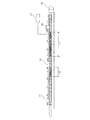
押出機のスクリュー概略を図3に示す。
メインフィード口11;C1
可塑化部12;C4〜C5(構成:上流側より、順ニーディング、逆ニーディング、長さ128mm)
サイドフィード口13;C5
混練部14;C6〜C8(構成:上流側より、順ニーディング、直交ニーディング、逆ニーディング、逆フライト、順ニーディング、逆ニーディング、逆フライト、長さ352mm)
メインフィード口へのフィーダー;日本製鋼所製スクリュー式ロスインウェイトフィーダー
サイドフィード口へのフィーダー;
ペレット樹脂;K−TRON社製スクリュー式ロスインウェイトフィーダー
ガラス繊維;日本製鋼所製スクリュー式ロスインウェイトフィーダー
(押出条件)
シリンダー温度;メインフィード口11のシリンダーC1のみが200℃であり、他のシリンダー温度は全て350℃とした。
ダイ温度;350℃
(組成物の混練および押出方法)
上記二軸スクリュー押出機を用い、液晶性ポリマーのペレットをメインフィード口11及びサイドフィード口13から供給し、滑剤をメインフィード口11から、ガラス繊維をサイドフィード口13から供給した。サイドフィード口には、二軸
サイドフィーダーを用いて供給し、液晶性ポリマーペレット、滑剤、ガラス繊維の割合は表1の割合になるように、重量フィーダーを用いて制御した。スクリュー回転数及び押出量は表1のように設定し、ダイ16からストランド状に吐出させた溶融樹脂組成物をタナカ製作所製メッシュベルトコンベアで搬送しつつ、スプレー噴霧水により冷却した後、カッティングしペレットを得た。このペレットから射出成形機により上記試験片を作製し、評価したところ、表2に示す結果を得た。
Furthermore, using a large tabletop reflow soldering device RF-300 manufactured by Japan Pulse Technology Laboratory, after heating at a peak temperature of 250 ° C. and a heating time of 5 minutes, the flatness was measured by the method described above, and before and after the reflow. The difference in flatness was determined.
[Molding condition]
Molding machine: FANUC α-50C (using medium diameter long nozzle)
Cylinder temperature: 350 ℃ -350 ℃ -340 ℃ -330 ℃
(nozzle)
Mold temperature: 80 ℃
Injection speed: 200mm / sec
Holding pressure: 29MPa
Filling time: 0.08sec
Holding pressure time: 1 sec
Cooling time: 5 sec
Screw rotation speed: 120rpm
Screw back pressure: 0.5MPa
(4) Flexural modulus
An injection molded piece of 125 mm x 12.7 mm x 0.8 mm was used and measured according to ASTM D790.
Examples 1-5 and Comparative Examples 1-9
When the said test piece of the liquid crystalline polymer composition containing glass fiber was produced and evaluated on condition of the following, the result shown in Table 2 was obtained.
[Production conditions]
(Used ingredients)
・ Polymer: Liquid crystalline polymer pellet (Polyplastics Co., Ltd., Vectra E950i), melting point 335 ° C.,
・ Glass fiber
(1) Those used in Examples 1 to 5 and Comparative Examples 1 to 8;
CS03JA419 manufactured by Asahi Fiber Glass Co., Ltd. (chopped strand fiber with a fiber diameter of 10 μm)
(2) used in Comparative Example 9;
Nittobo PF70 (fiber diameter 10μm, fiber length 80μm milled fiber)
・ Lubricant: Unistar H-476 manufactured by NOF Corporation
(Compound equipment)
・ Extruder: Nippon Steel Works, twin screw extruder TEX-30α (screw diameter: 32 mm, L / D: 38.5)
An outline of the screw of the extruder is shown in FIG.
Main feed port 11; C1
Plasticizing section 12: C4 to C5 (configuration: forward kneading, reverse kneading, length 128mm from upstream side)
Kneading unit 14: C6 to C8 (configuration: from upstream, forward kneading, orthogonal kneading, reverse kneading, reverse flight, forward kneading, reverse kneading, reverse flight, length 352 mm)
Feeder to the main feed port; Feeder to the screw-type loss-in-weight feeder side feed port made by Nippon Steel Works;
Pellet resin; K-TRON screw-type loss-in-weight feeder Glass fiber; Nippon Steel Works screw-type loss-in-weight feeder (extrusion conditions)
Cylinder temperature: Only the cylinder C1 of the main feed port 11 was 200 ° C, and the other cylinder temperatures were all 350 ° C.
Die temperature: 350 ° C
(Method of kneading and extruding the composition)
Using the above twin screw extruder, liquid crystalline polymer pellets were supplied from the main feed port 11 and
尚、実施例・比較例の各複合樹脂組成物におけるガラス繊維の配合量と重量平均長さとの関係を、図1にプロットした。 In addition, the relationship between the compounding quantity of the glass fiber and weight average length in each composite resin composition of an Example and a comparative example was plotted in FIG.
1…樹脂溜り
2…ピッチ間隔
3…格子部の厚み
11…メインフィード口
12…可塑化部
13…サイドフィード口
14…混練部
15…ベント口
16…ダイ
17…減圧装置
DESCRIPTION OF SYMBOLS 1 ...
11 ... Main feed port
12 ... Plasticizing part
13 ... Side feed port
14 ... Kneading part
15 ... Vent port
16 ... Die
17 ... decompression device
Claims (3)
[領域(D)]
X軸を(B) ガラス繊維の配合量((C) 複合樹脂組成物中の重量%)、Y軸を(B) ガラス繊維の重量平均長さ(μm)として、以下の(1) 〜(5) の関数で囲まれる領域
(1) X=40
(2) X=53
(3) Y=160
(4) Y=360
(5) Y=(18222/X)−84.44 (A) (B) Glass fiber blended with liquid crystalline polymer (C) Composite resin composition (however, the relationship between the blended amount of (B) glass fiber blended and the weight average length is the following region (D) Of the outer frame, which has a lattice structure inside the outer frame, the pitch interval of the lattice portion is 2 mm or less, the thickness of the lattice portion is 0.5 mm or less, and the overall height of the product is 5.0 mm or less planar connector.
[Area (D)]
With the X axis as the blending amount of (B) glass fiber ((C) wt% in the composite resin composition) and the Y axis as the weight average length (μm) of (B) glass fiber, the following (1) to ( 5) Area surrounded by function
(1) X = 40
(2) X = 53
(3) Y = 160
(4) Y = 360
(5) Y = (18222 / X) −84.44
Priority Applications (4)
| Application Number | Priority Date | Filing Date | Title |
|---|---|---|---|
| JP2004092020A JP4717366B2 (en) | 2004-03-26 | 2004-03-26 | Planar connector |
| TW94107779A TWI343676B (en) | 2004-03-26 | 2005-03-15 | Planar connector |
| PCT/JP2005/006220 WO2005093909A1 (en) | 2004-03-26 | 2005-03-24 | Planar connector |
| CNB2005800094012A CN100539317C (en) | 2004-03-26 | 2005-03-24 | Planar connector |
Applications Claiming Priority (1)
| Application Number | Priority Date | Filing Date | Title |
|---|---|---|---|
| JP2004092020A JP4717366B2 (en) | 2004-03-26 | 2004-03-26 | Planar connector |
Publications (3)
| Publication Number | Publication Date |
|---|---|
| JP2005276758A JP2005276758A (en) | 2005-10-06 |
| JP2005276758A5 JP2005276758A5 (en) | 2007-04-05 |
| JP4717366B2 true JP4717366B2 (en) | 2011-07-06 |
Family
ID=35056509
Family Applications (1)
| Application Number | Title | Priority Date | Filing Date |
|---|---|---|---|
| JP2004092020A Expired - Lifetime JP4717366B2 (en) | 2004-03-26 | 2004-03-26 | Planar connector |
Country Status (4)
| Country | Link |
|---|---|
| JP (1) | JP4717366B2 (en) |
| CN (1) | CN100539317C (en) |
| TW (1) | TWI343676B (en) |
| WO (1) | WO2005093909A1 (en) |
Families Citing this family (10)
| Publication number | Priority date | Publication date | Assignee | Title |
|---|---|---|---|---|
| JP5332188B2 (en) * | 2007-02-26 | 2013-11-06 | 住友化学株式会社 | Resin molded body and method for producing the same |
| JP5165492B2 (en) * | 2008-05-23 | 2013-03-21 | ポリプラスチックス株式会社 | Planar connector |
| JP2010037364A (en) * | 2008-07-31 | 2010-02-18 | Polyplastics Co | Connector |
| TW201132747A (en) | 2009-11-16 | 2011-10-01 | Sumitomo Chemical Co | Liquid crystalline polyester composition for connector and connector using the same |
| JP5485216B2 (en) | 2011-04-01 | 2014-05-07 | ポリプラスチックス株式会社 | Planar connector |
| JP6185922B2 (en) * | 2011-11-15 | 2017-08-23 | ティコナ・エルエルシー | Fine pitch electrical connector and thermoplastic composition used therein |
| JP5753143B2 (en) | 2012-09-21 | 2015-07-22 | ポリプラスチックス株式会社 | Totally aromatic polyester and polyester resin composition, and polyester molded article |
| JP5753144B2 (en) | 2012-09-21 | 2015-07-22 | ポリプラスチックス株式会社 | Totally aromatic polyester and polyester resin composition, and polyester molded article |
| CN104662087B (en) | 2012-09-27 | 2016-08-17 | 宝理塑料株式会社 | Composite resin composition and the planar connector being molded with by this composite resin composition |
| CN113201229A (en) * | 2021-05-14 | 2021-08-03 | 金发科技股份有限公司 | Liquid crystal polymer composite material and application thereof |
Family Cites Families (6)
| Publication number | Priority date | Publication date | Assignee | Title |
|---|---|---|---|---|
| US4540737A (en) * | 1983-02-07 | 1985-09-10 | Celanese Corporation | Method for the formation of composite articles comprised of thermotropic liquid crystalline polymers and articles produced thereby |
| JP2579742B2 (en) * | 1995-02-20 | 1997-02-12 | ポリプラスチックス株式会社 | Injection molding composition |
| JP3683080B2 (en) * | 1997-09-25 | 2005-08-17 | 三菱エンジニアリングプラスチックス株式会社 | Resin composition, injection molded product having hollow portion, and injection molding method |
| JP2000026743A (en) * | 1998-07-15 | 2000-01-25 | Toray Ind Inc | Liquid crystalline resin composition |
| JP4118425B2 (en) * | 1998-12-18 | 2008-07-16 | ポリプラスチックス株式会社 | Liquid crystalline polymer composition for connector and connector |
| JP2002194188A (en) * | 2000-12-26 | 2002-07-10 | Toray Ind Inc | Flame-retardant liquid crystal polyester resin composition |
-
2004
- 2004-03-26 JP JP2004092020A patent/JP4717366B2/en not_active Expired - Lifetime
-
2005
- 2005-03-15 TW TW94107779A patent/TWI343676B/en active
- 2005-03-24 WO PCT/JP2005/006220 patent/WO2005093909A1/en active Application Filing
- 2005-03-24 CN CNB2005800094012A patent/CN100539317C/en active Active
Also Published As
| Publication number | Publication date |
|---|---|
| TW200537757A (en) | 2005-11-16 |
| JP2005276758A (en) | 2005-10-06 |
| TWI343676B (en) | 2011-06-11 |
| WO2005093909A1 (en) | 2005-10-06 |
| CN1934756A (en) | 2007-03-21 |
| CN100539317C (en) | 2009-09-09 |
Similar Documents
| Publication | Publication Date | Title |
|---|---|---|
| US7789670B2 (en) | Planar connector | |
| JP5385609B2 (en) | Method for producing liquid crystalline polyester composition | |
| JP4602024B2 (en) | Method for producing liquid crystalline resin composition | |
| JP3686718B2 (en) | Liquid crystalline polymer composition and molded article | |
| TWI393620B (en) | Method for producing resin composition pellet with length of fibrous filler controlled | |
| JP4786648B2 (en) | Manufacturing method of resin composition with high concentration of fibrous filler and resin composition pellet | |
| WO2005093909A1 (en) | Planar connector | |
| JPH10219085A (en) | Liquid crystal polyester resin composition | |
| JP2010003661A (en) | Plane-form connector | |
| JP2003268252A (en) | Liquid crystalline polymer composition | |
| KR102498397B1 (en) | electronics housing | |
| JP2012214702A (en) | Resin composition and molded article made of the resin composition | |
| US9893442B2 (en) | Actuator | |
| US7547403B2 (en) | Electroconductive resin composition | |
| KR101737036B1 (en) | Liquid crystalline resin composition | |
| KR102376572B1 (en) | Liquid crystalline polyester resin composition | |
| EP2206744B1 (en) | Liquid crystalline polyester resin composition | |
| KR101783505B1 (en) | Wholly aromatic liquid crystalline polyester resin compound having improved surface properties and impact resistance | |
| JP5063903B2 (en) | Information recording medium parts | |
| JP5063901B2 (en) | Thermoplastic resin composition | |
| KR101660242B1 (en) | Thermoplastic resin composition having improved impact resistant and appearance for mobile housing | |
| KR101812367B1 (en) | Wholly aromatic liquid crystalline polyester resin compound with excellent releasing property and measurability and method for preparing the same | |
| KR101481840B1 (en) | Liquid crystalline polymer composition | |
| JP5815061B2 (en) | Injection molded product and its manufacturing method |
Legal Events
| Date | Code | Title | Description |
|---|---|---|---|
| A521 | Request for written amendment filed |
Free format text: JAPANESE INTERMEDIATE CODE: A523 Effective date: 20070215 |
|
| A621 | Written request for application examination |
Free format text: JAPANESE INTERMEDIATE CODE: A621 Effective date: 20070215 |
|
| A131 | Notification of reasons for refusal |
Free format text: JAPANESE INTERMEDIATE CODE: A131 Effective date: 20090915 |
|
| A02 | Decision of refusal |
Free format text: JAPANESE INTERMEDIATE CODE: A02 Effective date: 20100511 |
|
| A521 | Request for written amendment filed |
Free format text: JAPANESE INTERMEDIATE CODE: A523 Effective date: 20100804 |
|
| A911 | Transfer to examiner for re-examination before appeal (zenchi) |
Free format text: JAPANESE INTERMEDIATE CODE: A911 Effective date: 20100825 |
|
| A131 | Notification of reasons for refusal |
Free format text: JAPANESE INTERMEDIATE CODE: A131 Effective date: 20101221 |
|
| A521 | Request for written amendment filed |
Free format text: JAPANESE INTERMEDIATE CODE: A523 Effective date: 20101221 |
|
| TRDD | Decision of grant or rejection written | ||
| A01 | Written decision to grant a patent or to grant a registration (utility model) |
Free format text: JAPANESE INTERMEDIATE CODE: A01 Effective date: 20110329 |
|
| A01 | Written decision to grant a patent or to grant a registration (utility model) |
Free format text: JAPANESE INTERMEDIATE CODE: A01 |
|
| A61 | First payment of annual fees (during grant procedure) |
Free format text: JAPANESE INTERMEDIATE CODE: A61 Effective date: 20110330 |
|
| R150 | Certificate of patent or registration of utility model |
Ref document number: 4717366 Country of ref document: JP Free format text: JAPANESE INTERMEDIATE CODE: R150 Free format text: JAPANESE INTERMEDIATE CODE: R150 |
|
| FPAY | Renewal fee payment (event date is renewal date of database) |
Free format text: PAYMENT UNTIL: 20140408 Year of fee payment: 3 |
|
| R250 | Receipt of annual fees |
Free format text: JAPANESE INTERMEDIATE CODE: R250 |
|
| R250 | Receipt of annual fees |
Free format text: JAPANESE INTERMEDIATE CODE: R250 |
|
| R250 | Receipt of annual fees |
Free format text: JAPANESE INTERMEDIATE CODE: R250 |
|
| R250 | Receipt of annual fees |
Free format text: JAPANESE INTERMEDIATE CODE: R250 |
|
| R250 | Receipt of annual fees |
Free format text: JAPANESE INTERMEDIATE CODE: R250 |
|
| R250 | Receipt of annual fees |
Free format text: JAPANESE INTERMEDIATE CODE: R250 |
|
| R250 | Receipt of annual fees |
Free format text: JAPANESE INTERMEDIATE CODE: R250 |
|
| R250 | Receipt of annual fees |
Free format text: JAPANESE INTERMEDIATE CODE: R250 |
|
| R250 | Receipt of annual fees |
Free format text: JAPANESE INTERMEDIATE CODE: R250 |
|
| R250 | Receipt of annual fees |
Free format text: JAPANESE INTERMEDIATE CODE: R250 |