JP4709551B2 - Rapid exchange dilatation catheter for nonvascular applications - Google Patents
Rapid exchange dilatation catheter for nonvascular applications Download PDFInfo
- Publication number
- JP4709551B2 JP4709551B2 JP2004565164A JP2004565164A JP4709551B2 JP 4709551 B2 JP4709551 B2 JP 4709551B2 JP 2004565164 A JP2004565164 A JP 2004565164A JP 2004565164 A JP2004565164 A JP 2004565164A JP 4709551 B2 JP4709551 B2 JP 4709551B2
- Authority
- JP
- Japan
- Prior art keywords
- catheter
- lumen
- guide wire
- rigid member
- proximal end
- Prior art date
- Legal status (The legal status is an assumption and is not a legal conclusion. Google has not performed a legal analysis and makes no representation as to the accuracy of the status listed.)
- Expired - Lifetime
Links
- 239000012530 fluid Substances 0.000 claims abstract description 14
- 230000007246 mechanism Effects 0.000 claims description 2
- 239000000463 material Substances 0.000 claims 1
- 238000000034 method Methods 0.000 abstract description 19
- 238000002594 fluoroscopy Methods 0.000 description 5
- 230000008569 process Effects 0.000 description 5
- 239000003814 drug Substances 0.000 description 4
- 238000003780 insertion Methods 0.000 description 4
- 230000037431 insertion Effects 0.000 description 4
- 229940124597 therapeutic agent Drugs 0.000 description 4
- 239000002872 contrast media Substances 0.000 description 3
- 238000013459 approach Methods 0.000 description 2
- 210000000013 bile duct Anatomy 0.000 description 2
- 210000001035 gastrointestinal tract Anatomy 0.000 description 2
- 238000001802 infusion Methods 0.000 description 2
- 230000002792 vascular Effects 0.000 description 2
- 208000033991 Device difficult to use Diseases 0.000 description 1
- 239000004606 Fillers/Extenders Substances 0.000 description 1
- FAPWRFPIFSIZLT-UHFFFAOYSA-M Sodium chloride Chemical compound [Na+].[Cl-] FAPWRFPIFSIZLT-UHFFFAOYSA-M 0.000 description 1
- 230000002159 abnormal effect Effects 0.000 description 1
- 210000003484 anatomy Anatomy 0.000 description 1
- 210000001124 body fluid Anatomy 0.000 description 1
- 239000010839 body fluid Substances 0.000 description 1
- 210000003459 common hepatic duct Anatomy 0.000 description 1
- 238000012790 confirmation Methods 0.000 description 1
- 239000000356 contaminant Substances 0.000 description 1
- 230000010339 dilation Effects 0.000 description 1
- 230000002440 hepatic effect Effects 0.000 description 1
- 238000012986 modification Methods 0.000 description 1
- 230000004048 modification Effects 0.000 description 1
- 210000000277 pancreatic duct Anatomy 0.000 description 1
- 230000007170 pathology Effects 0.000 description 1
- 239000002861 polymer material Substances 0.000 description 1
- 239000011780 sodium chloride Substances 0.000 description 1
- 238000010561 standard procedure Methods 0.000 description 1
- 239000000126 substance Substances 0.000 description 1
- 210000003437 trachea Anatomy 0.000 description 1
- 230000024883 vasodilation Effects 0.000 description 1
Images


Classifications
-
- A—HUMAN NECESSITIES
- A61—MEDICAL OR VETERINARY SCIENCE; HYGIENE
- A61M—DEVICES FOR INTRODUCING MEDIA INTO, OR ONTO, THE BODY; DEVICES FOR TRANSDUCING BODY MEDIA OR FOR TAKING MEDIA FROM THE BODY; DEVICES FOR PRODUCING OR ENDING SLEEP OR STUPOR
- A61M29/00—Dilators with or without means for introducing media, e.g. remedies
- A61M29/02—Dilators made of swellable material
-
- A—HUMAN NECESSITIES
- A61—MEDICAL OR VETERINARY SCIENCE; HYGIENE
- A61M—DEVICES FOR INTRODUCING MEDIA INTO, OR ONTO, THE BODY; DEVICES FOR TRANSDUCING BODY MEDIA OR FOR TAKING MEDIA FROM THE BODY; DEVICES FOR PRODUCING OR ENDING SLEEP OR STUPOR
- A61M25/00—Catheters; Hollow probes
- A61M25/01—Introducing, guiding, advancing, emplacing or holding catheters
- A61M25/0102—Insertion or introduction using an inner stiffening member, e.g. stylet or push-rod
-
- A—HUMAN NECESSITIES
- A61—MEDICAL OR VETERINARY SCIENCE; HYGIENE
- A61M—DEVICES FOR INTRODUCING MEDIA INTO, OR ONTO, THE BODY; DEVICES FOR TRANSDUCING BODY MEDIA OR FOR TAKING MEDIA FROM THE BODY; DEVICES FOR PRODUCING OR ENDING SLEEP OR STUPOR
- A61M25/00—Catheters; Hollow probes
- A61M25/10—Balloon catheters
- A61M25/104—Balloon catheters used for angioplasty
-
- A—HUMAN NECESSITIES
- A61—MEDICAL OR VETERINARY SCIENCE; HYGIENE
- A61M—DEVICES FOR INTRODUCING MEDIA INTO, OR ONTO, THE BODY; DEVICES FOR TRANSDUCING BODY MEDIA OR FOR TAKING MEDIA FROM THE BODY; DEVICES FOR PRODUCING OR ENDING SLEEP OR STUPOR
- A61M25/00—Catheters; Hollow probes
- A61M25/0043—Catheters; Hollow probes characterised by structural features
- A61M2025/0063—Catheters; Hollow probes characterised by structural features having means, e.g. stylets, mandrils, rods or wires to reinforce or adjust temporarily the stiffness, column strength or pushability of catheters which are already inserted into the human body
-
- A—HUMAN NECESSITIES
- A61—MEDICAL OR VETERINARY SCIENCE; HYGIENE
- A61M—DEVICES FOR INTRODUCING MEDIA INTO, OR ONTO, THE BODY; DEVICES FOR TRANSDUCING BODY MEDIA OR FOR TAKING MEDIA FROM THE BODY; DEVICES FOR PRODUCING OR ENDING SLEEP OR STUPOR
- A61M25/00—Catheters; Hollow probes
- A61M25/01—Introducing, guiding, advancing, emplacing or holding catheters
- A61M2025/0177—Introducing, guiding, advancing, emplacing or holding catheters having external means for receiving guide wires, wires or stiffening members, e.g. loops, clamps or lateral tubes
-
- A—HUMAN NECESSITIES
- A61—MEDICAL OR VETERINARY SCIENCE; HYGIENE
- A61M—DEVICES FOR INTRODUCING MEDIA INTO, OR ONTO, THE BODY; DEVICES FOR TRANSDUCING BODY MEDIA OR FOR TAKING MEDIA FROM THE BODY; DEVICES FOR PRODUCING OR ENDING SLEEP OR STUPOR
- A61M25/00—Catheters; Hollow probes
- A61M25/01—Introducing, guiding, advancing, emplacing or holding catheters
- A61M2025/018—Catheters having a lateral opening for guiding elongated means lateral to the catheter
-
- A—HUMAN NECESSITIES
- A61—MEDICAL OR VETERINARY SCIENCE; HYGIENE
- A61M—DEVICES FOR INTRODUCING MEDIA INTO, OR ONTO, THE BODY; DEVICES FOR TRANSDUCING BODY MEDIA OR FOR TAKING MEDIA FROM THE BODY; DEVICES FOR PRODUCING OR ENDING SLEEP OR STUPOR
- A61M25/00—Catheters; Hollow probes
- A61M25/01—Introducing, guiding, advancing, emplacing or holding catheters
- A61M2025/0183—Rapid exchange or monorail catheters
-
- A—HUMAN NECESSITIES
- A61—MEDICAL OR VETERINARY SCIENCE; HYGIENE
- A61M—DEVICES FOR INTRODUCING MEDIA INTO, OR ONTO, THE BODY; DEVICES FOR TRANSDUCING BODY MEDIA OR FOR TAKING MEDIA FROM THE BODY; DEVICES FOR PRODUCING OR ENDING SLEEP OR STUPOR
- A61M25/00—Catheters; Hollow probes
- A61M25/01—Introducing, guiding, advancing, emplacing or holding catheters
- A61M25/06—Body-piercing guide needles or the like
- A61M25/0662—Guide tubes
- A61M2025/0681—Systems with catheter and outer tubing, e.g. sheath, sleeve or guide tube
-
- A—HUMAN NECESSITIES
- A61—MEDICAL OR VETERINARY SCIENCE; HYGIENE
- A61M—DEVICES FOR INTRODUCING MEDIA INTO, OR ONTO, THE BODY; DEVICES FOR TRANSDUCING BODY MEDIA OR FOR TAKING MEDIA FROM THE BODY; DEVICES FOR PRODUCING OR ENDING SLEEP OR STUPOR
- A61M25/00—Catheters; Hollow probes
- A61M25/0043—Catheters; Hollow probes characterised by structural features
- A61M25/0045—Catheters; Hollow probes characterised by structural features multi-layered, e.g. coated
-
- A—HUMAN NECESSITIES
- A61—MEDICAL OR VETERINARY SCIENCE; HYGIENE
- A61M—DEVICES FOR INTRODUCING MEDIA INTO, OR ONTO, THE BODY; DEVICES FOR TRANSDUCING BODY MEDIA OR FOR TAKING MEDIA FROM THE BODY; DEVICES FOR PRODUCING OR ENDING SLEEP OR STUPOR
- A61M25/00—Catheters; Hollow probes
- A61M25/01—Introducing, guiding, advancing, emplacing or holding catheters
- A61M25/0169—Exchanging a catheter while keeping the guidewire in place
Abstract
Description
本発明はカテーテルに関し、より詳細には、体腔の膨張に使用されるバルーンカテーテルに関する。 The present invention relates to a catheter, and more particularly to a balloon catheter used for inflation of a body cavity.
消化管、胆管分岐及び気管支系等の身体の様々な腔内の異常性病状を治療するための内視鏡による方法は、益々増えている。これらの方法では、内視鏡を用いて直接視認することにより、所望の腔、又は管の領域へ接近し得る。しかしながら、比較的狭い管では、X線透視法及びガイドワイヤと関連付けて使用するカテーテルによる接近のみ必要とされる。 Increasingly, endoscopic methods for treating abnormal pathologies in various cavities of the body, such as the gastrointestinal tract, bile duct bifurcation and bronchial system, are increasing. In these methods, a desired cavity or region of a tube can be approached by viewing directly with an endoscope. However, in a relatively narrow tube, only access with a catheter used in conjunction with fluoroscopy and a guide wire is required.
多くの場合、このような小径を有する管は、一つ以上のカテーテルの使用を要するため、処置中、カテーテルを交換する必要がある。カテーテルは、例えば管の解剖学的構造の詳細をX線透視するため使用される造影剤の送達、治療薬の送達、又は脈管膨張の遂行等の特化された用途を有する。最後のケースにおいて、カテーテルは拡張時に管を機械的に膨張させる拡張部分を有し得る。カテーテルの交換は、通常、ガイドワイヤ上において、第一のカテーテルを内視鏡から除去して、ガイドワイヤ上において第二のカテーテルを所望の治療部位へ前進させる。ガイドワイヤが一旦、目標領域に関して定位置に配置された際、その後のカテーテル交換等を含むカテーテル工程中、ガイドワイヤ位置を維持して、次に使用されるカテーテル、又は他の装置を目標領域へ配置することを促進することが非常に望ましい。この工程中、目標領域におけるガイドワイヤ位置が失われた場合、身体内の管を介してガイドワイヤを再誘導することは困難で、かつ時間を要する。 In many cases, a tube having such a small diameter requires the use of one or more catheters, which requires the catheter to be replaced during the procedure. Catheters have specialized uses such as delivery of contrast agents, delivery of therapeutic agents, or performance of vasodilation used to fluoroscopically detail the anatomy of a tube. In the last case, the catheter may have an expansion portion that mechanically expands the tube when expanded. Catheter replacement typically involves removing the first catheter from the endoscope over the guidewire and advancing the second catheter over the guidewire to the desired treatment site. Once the guidewire is in place with respect to the target area, the guidewire position is maintained during the catheter process, including subsequent catheter exchanges, and the next used catheter or other device to the target area. It is highly desirable to facilitate placement. During this process, if the guidewire position in the target area is lost, it is difficult and time consuming to re-guide the guidewire through a tube in the body.
内科医は通常、ガイドワイヤの位置を維持するため、ガイドワイヤ及び/又はカテーテルの基端を片手で把持して、他方の手でカテーテルの交換を実行する。ある工程においては、カテーテルを除去する際、標準的なガイドワイヤでは、その全長に沿ってカテーテルが移動されるため、内科医がカテーテルの把持を継続するに十分な長さを有さない。このような障害を緩和するため、ガイドワイヤ増量材(guide wire extender)等の付加的な器具が使用され得る。しかしながら、付加的な器具を使用するとカテーテル交換の際の複雑性が増し、また交換に要する時間が延長する。更に、延長されたガイドワイヤの長さ(2m迄、又はそれ以上)は、該工程中の装置の取扱いに第二の操作者を必要とし得る。 Physicians typically hold the guidewire and / or the proximal end of the catheter with one hand and perform a catheter exchange with the other hand to maintain the position of the guidewire. In some processes, when removing a catheter, a standard guidewire is not long enough for the physician to continue grasping the catheter because the catheter is moved along its entire length. To alleviate such obstacles, additional devices such as guide wire extenders can be used. However, the use of additional instruments increases the complexity of the catheter exchange and increases the time required for the exchange. Furthermore, the length of the extended guidewire (up to 2 m or more) may require a second operator to handle the device during the process.
本発明は、カテーテル先端の先端側孔から、カテーテル基端より隔離された基端側孔へ延びるガイドワイヤルーメンと、基端側孔からカテーテル基端へ延びる剛性部材とを有する、体腔に挿入される可撓性を備えたカテーテルに関する。 The present invention is inserted into a body cavity having a guide wire lumen extending from a distal end side hole of a catheter distal end to a proximal end side hole isolated from the proximal end of the catheter, and a rigid member extending from the proximal end side hole to the proximal end of the catheter. The present invention relates to a flexible catheter.
本発明は更に、体腔の目標領域において組織を治療する方法に関する。本方法は、体腔を介してガイドワイヤを目標領域へと挿入する工程と、カテーテルのガイドワイヤルーメンの先端側孔内へガイドワイヤの基端を挿入して、ガイドワイヤがカテーテルの基端から離間されたガイドワイヤルーメンの基端側孔から退出する迄、カテーテルをガイドワイヤに沿って摺動させる工程とを含む。カテーテルは、該カテーテルの基端からガイドワイヤルーメンの基端側孔に隣接する位置へ延びる剛性部材を有する。前記工程は更に、ガイドワイヤに沿ってカテーテルを目標領域へ摺動させる工程と、カテーテルを使用して目標領域において組織を治療する工程とを含む。
本発明は更に、体腔に挿入される可撓性を備えたカテーテルに関し、前記カテーテルの先端に設けられた先端側孔から、該カテーテルの基端から先端方向へ離間する位置に設けられた基端側孔へ延びる、ガイドワイヤを収容するためのガイドワイヤルーメンと、前記ガイドワイヤルーメンから隔離された剛性部材ルーメンと、前記剛性部材ルーメンはカテーテルの基端からカテーテルの先端の開口へ延びて、該剛性部材ルーメンに供給された流体がカテーテルの先端に隣接する体腔領域へ送達されることと、前記剛性部材ルーメン内にてカテーテルの基端から前記基端側孔の隣接位置へ延びる剛性を備えた剛性部材とを有し、前記剛性部材は、前記剛性部材ルーメンから取り外し可能であることとを特徴とする。
The invention further relates to a method of treating tissue in a target region of a body cavity. The method includes inserting a guide wire into a target region through a body cavity and inserting the proximal end of the guide wire into the distal hole of the guide wire lumen of the catheter so that the guide wire is separated from the proximal end of the catheter. Sliding the catheter along the guide wire until it exits from the proximal hole of the guide wire lumen. The catheter has a rigid member that extends from the proximal end of the catheter to a location adjacent to the proximal bore of the guidewire lumen. The steps further include sliding the catheter along the guide wire to the target area and treating the tissue at the target area using the catheter.
The present invention further relates to a flexible catheter to be inserted into a body cavity, and a proximal end provided at a position spaced from the proximal end of the catheter in the distal direction from a distal side hole provided at the distal end of the catheter. A guidewire lumen for receiving a guidewire extending into the side hole; a rigid member lumen isolated from the guidewire lumen; and the rigid member lumen extends from a proximal end of the catheter to an opening at the distal end of the catheter, The fluid supplied to the rigid member lumen is delivered to a body cavity region adjacent to the distal end of the catheter, and has rigidity to extend from the proximal end of the catheter to the adjacent position of the proximal side hole in the rigid member lumen. A rigid member, wherein the rigid member is removable from the rigid member lumen.
本発明は、以下の説明と、類似した要素に同一の参照番号が付された添付の図面とを参照にして、更に理解が深まるであろう。本発明の実施形態によれば、迅速交換カテーテルは、任意の身体の様々な腔、特に胃腸管、胆管、肝管及び膵管、気管等の非脈管体腔を膨張させるために使用される。しかしながら、当業者は本発明のカテーテルは内科医が膨張を希望する任意の体腔に使用され得ることを理解するであろう。以下に説明するように、カテーテルは、本願に説明されている様々な機能のいくつか、又は全てに適用するルーメン、及び任意の他の公知の目的に使用されるルーメンを備えてもよい。 The present invention will be further understood with reference to the following description and the appended drawings, wherein like elements are given the same reference numerals. According to embodiments of the present invention, rapid exchange catheters are used to inflate various body cavities, especially non-vascular body cavities such as the gastrointestinal tract, bile duct, hepatic and pancreatic ducts, trachea and the like. However, those skilled in the art will appreciate that the catheter of the present invention can be used in any body cavity that a physician desires to expand. As described below, the catheter may include a lumen that applies to some or all of the various functions described herein, and a lumen used for any other known purpose.
本発明による実施形態は、ガイドワイヤ上へカテーテルを挿入することを容易にし、かつガイドワイヤの目標領域における位置を変更することなく、カテーテルを交換することを容易にする。以下にて詳細に説明するように、本発明の実施形態では、比較的短いガイドワイヤを使用し得るとともに、交換処置中、内科医がワイヤの堅固な把持を継続することが可能である。 Embodiments in accordance with the present invention facilitate insertion of a catheter over a guidewire and facilitate replacement of the catheter without changing the position of the guidewire in the target area. As described in detail below, embodiments of the present invention may use a relatively short guidewire and allow the physician to continue to firmly grasp the wire during the replacement procedure.
狭い非脈管の目標通路、即ち目標管内でカテーテルを用いる典型的な処置においては、まず内視鏡、又は気管支鏡を挿入して、目標通路に至る比較的広い体腔を視認化し得る。内視鏡はサイズが大きいため、小径を有する管内に位置する目標領域へ、内視鏡を直接接近させることは不可能であり得る。そのため、この小径管への接近は、カテーテルとガイドワイヤの組み合わせを、内視鏡から先端方向へと、小径を有する管を介して目標領域へ延ばすことにより実行される必要がある。ガイドワイヤは、多くの場合、最初にX線透視下で、又は他の公知の一方法によって挿入される。ガイドワイヤは、内視鏡のルーメン内から延ばされるか、又は内視鏡と並行して個別に挿入され得る。従って、ガイドワイヤは、内視鏡とX線透視法の双方にて視認され得る。一旦、ガイドワイヤの先端が目標領域に到達したら、該ガイドワイヤを定位置にて保持することが重要である。位置が失われた場合、ガイドワイヤを再びその位置に誘導する必要があり、処置に要する時間が相当追加される。 In a typical non-vascular target passage, i.e., a typical procedure using a catheter in the target tube, an endoscope or bronchoscope can be inserted first to visualize a relatively wide body cavity leading to the target passage. Due to the large size of the endoscope, it may not be possible to have the endoscope directly approach a target area located within a tube having a small diameter. Therefore, the approach to the small diameter tube needs to be performed by extending the combination of the catheter and the guide wire from the endoscope in the distal direction to the target region through the small diameter tube. The guide wire is often inserted first under fluoroscopy or by another known method. The guidewire can be extended from within the lumen of the endoscope or inserted separately in parallel with the endoscope. Therefore, the guide wire can be visually recognized by both the endoscope and the X-ray fluoroscopy. Once the tip of the guide wire reaches the target area, it is important to hold the guide wire in place. If the position is lost, it is necessary to guide the guidewire back to that position, adding considerable time to the procedure.
一旦、ガイドワイヤを定位置に配置したら、カテーテルを内視鏡等のルーメン内から、ガイドワイヤに沿って目標領域へと延ばし得る。カテーテルは、ガイドワイヤが通過するガイドワイヤルーメンを有してもよい。カテーテルはガイドワイヤ上に差し込まれてもよく、それによりガイドワイヤは、カテーテル先頭の付近にてガイドワイヤルーメン内に入り込み、カテーテル全長の一部に沿ってカテーテルを辿って、カテーテルのより基端位置にて退出する。ガイドワイヤは、カテーテルのガイドワイヤルーメン内において長手方向に摺動可能であるが、ガイドワイヤルーメンの壁によって径方向に拘束されている。ガイドワイヤはカテーテルを誘導すると共に、カテーテルに所定量の剛性を付与して、内部にガイドワイヤが存在しない場合に容易に発生し得るカテーテルの歪みを防止する。 Once the guidewire is in place, the catheter can be extended from within the lumen, such as an endoscope, along the guidewire to the target area. The catheter may have a guidewire lumen through which the guidewire passes. The catheter may be inserted over the guide wire so that the guide wire enters the guide wire lumen near the top of the catheter and follows the catheter along a portion of the total length of the catheter, leading to the more proximal position of the catheter. Exit at. The guidewire is slidable longitudinally within the guidewire lumen of the catheter, but is radially constrained by the guidewire lumen wall. The guidewire guides the catheter and imparts a predetermined amount of stiffness to the catheter to prevent catheter distortion that can easily occur when no guidewire is present therein.
図1に、本発明による迅速交換膨張カテーテル10の代表的な実施形態を示す。上述し、また当業者が理解し得るように、膨張カテーテル10は内視鏡、又は気管支鏡(図示せず)から身体内に延伸されるか、又は用途に応じて、体腔に直接挿入され得る。膨張カテーテル10は、先端22及び基端24から延びている。先端22は、例えば天然の身体開口、又は外科的開口等を介して体腔に挿入されるように構成されている一方、基端24は、通常、全工程において体腔の外部に残留し、かつカテーテル10の操作に必要なハンドル、様々なアクチュエータ又は制御装置、及び接合部を備え得る。当業者が理解し得るように、カテーテル10は、狭い体腔及び管を介してガイドワイヤに沿って移動し得るよう可撓性を備えたマルチルーメンカテーテルであることが好ましい。本発明の範囲内において、カテーテルの異なる構成的構造を使用し得ることが理解されるであろう。
FIG. 1 shows an exemplary embodiment of a rapid
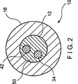
図1〜図3に示すように、カテーテル10は、治療されるべき領域の内腔を膨張させる拡張要素を備え得る。拡張要素は、先端22の近傍に形成されたバルーン部分16を有してもよく、膨張の際、ガイドワイヤ14の先端26によって正確に定められた内腔内の目標位置に隣接するルーメンの直径を拡張させる。このように、カテーテル10をガイドワイヤ14に沿って移動することによって、バルーン部分16は正確に目標位置へ移動され得る。当業者が理解し得るように、バルーン部分16は、一端が流体供給チューブ30に、他端がバルーン部分16に接続され得る膨張ルーメン34を介して、膨張流体源に連結され得る。バルーン部分16は、弁、又は他の制御装置32を使用して膨張流体を選択的に導入、又は除去することによって、拡張されるか、又は潰されてもよい。理解し得るように、膨張流体は空気、生理食塩水、又は他の適切な流体からなり得る。
As shown in FIGS. 1-3, the
上述したように、本発明のガイドワイヤ14を使用してカテーテル10の先端22を目標領域に正確に配置し得る。上述したように、ガイドワイヤ14を治療されるべき体腔又は管内に挿入して、ガイドワイヤ14の先端26を目標領域の隣接位置へ誘導する。その後、ガイドワイヤ14の基端をカテーテル10のガイドワイヤルーメン42内に挿入して、カテーテル10の先端22もまた目標領域に隣接する迄、ガイドワイヤ14に沿ってカテーテル10を押進する。図示する代表的な実施形態よれば、図2に示すように、ガイドワイヤルーメン42は先端側孔18から基端側孔20へ延びており、バルーン部分16の下方を通過している。ガイドワイヤ14は、先端側孔18を介してガイドワイヤルーメン42内に挿入されて、バルーン部分16の下方全体に亘って摺動されて基端側孔20から退出する。先端側孔18は、例えば先端22に形成されており、ガイドワイヤ14はカテーテル10の軸線にほぼ沿って、先端22から退出し得る。基端側孔20は、例えばカテーテル10の基端から離間されたカテーテル10の側部面上に形成されており、ガイドワイヤ14は角度をなして基端側孔20から退出して、カテーテル10の基端部を通過しない。
As described above, the
上述したように、従来のオーバー・ザ・ワイヤカテーテルでは、ガイドワイヤがカテーテルの全長に差し込まれるため、カテーテル長の2倍の長さを有するガイドワイヤを必要とする。このようなガイドワイヤ長は、特にガイドワイヤを定位置に維持する一方でカテーテルを交換する際の、装置の取扱いを困難にする。本発明の実施形態によれば、ガイドワイヤ14は先端側孔18と基端側孔20間のカテーテル10部分を介して延びるのみで、基端側孔20の基端側のカテーテル10部分を介して延びる必要がないため、ガイドワイヤ14は相当短くなり得る。先端側孔18と基端側孔20間の距離は、カテーテル10全長と比較して相当短いことが好ましく、それによりガイドワイヤ14は、適切に機能するためにカテーテル10よりも長くされる必要がない。例えば、100cmの長さを有するカテーテル10では、ガイドワイヤルーメン42の基端側孔20は、バルーン部分16基端から約10cmの位置に配置される。バルーン部分16として使用されるバルーンの長さに応じて、バルーン基端から先端側孔18迄の距離が変動し得ることが理解されるであろう。一般に、バルーンは、2〜10cmの長さを有する。先端側孔18と基端側孔20間におけるガイドワイヤルーメン42の長さは、先端22及びバルーン部分16を目標領域に誘導し得る最小の長さに保持される。好ましい実施形態において、カテーテル10は少なくとも目標領域に関して正確に配置される必要のある膨張機構、例えばバルーン部分16を収容する部分内にて、ガイドワイヤ14上に差し込まれる。一実施形態では、ガイドワイヤルーメンは、約10〜15cmの長さを有することが好ましい。
As described above, in the conventional over-the-wire catheter, since the guide wire is inserted into the entire length of the catheter, a guide wire having a length twice as long as the catheter length is required. Such a guidewire length makes the device difficult to handle, especially when changing the catheter while maintaining the guidewire in place. According to the embodiment of the present invention, the
本発明によるカテーテル10は、ガイドワイヤ14上において、第一カテーテル10を任意の構成を有し得る第二カテーテル10と交換するために、第一カテーテル10がガイドワイヤ14から除去される必要がある場合に特に有用である。上述したように、ガイドワイヤ14の短い部分のみがガイドワイヤルーメン42内に収容されるため、第一カテーテル10を身体から除去する間、操作者はガイドワイヤ14の手による操作を継続し得る
。即ち、ガイドワイヤ14の殆どはカテーテル10の外部に存在して接触可能であるため、操作者はガイドワイヤ14の体腔の挿入地点付近においてガイドワイヤ14を把持して、カテーテル10が後退される際のガイドワイヤ14の定位置からの移動を、手動により阻止し得る。基端側孔20が身体から退出する際、操作者は、先端側孔18が身体から退出する迄、ガイドワイヤ14のより基端側部分を把持し得る。この時点で、操作者は、先端側孔18から身体内へ延びているガイドワイヤ14部分を把持しながら、カテーテル10をガイドワイヤ14から完全に除去することが可能である。その後、ガイドワイヤ14基端が標準的方法によって第二カテーテル内に挿入されて、第二カテーテルがガイドワイヤ14に沿って目標領域へと前進され得る。このように、操作者は全操作工程の間、ガイドワイヤ14の把持を維持して、ガイドワイヤ14の目標領域における位置を維持し得る。
The
第一カテーテル10を除去した後、第二カテーテルのガイドワイヤルーメン内にガイドワイヤ14を挿入して、ガイドワイヤ14に沿って第二カテーテルを目標領域へと摺動させることによって、第二カテーテルを前進させ得る。第二カテーテルも本発明によるカテーテル10と同様に形成されている場合、ガイドワイヤ14は、先端側孔18内に挿入されて基端側孔20から引き抜かれ、ガイドワイヤ14の基端部を把持して、目標領域に隣接したガイドワイヤ14位置を保持しながら、体腔内に挿入されるものと想定される。このように、全操作が補助のない一人の操作者により実行され得る。
After removing the
カテーテル10は、カテーテル10の基端24から、カテーテル10の一部に沿って先端方向に延びる剛性部材36も有し得る。剛性部材36は、カテーテル10の長手方向における強度と堅さとを増大させて、該装置の脈管内への挿入を容易にする。より詳細には、剛性部材36は、ガイドワイヤ14がカテーテル10の外部に存在するカテーテル10の基端部(即ち、基端側孔20より基端側のカテーテル10部分)を堅くする。それ故、ガイドワイヤ14がカテーテル10の基端部内に存在しなくてもカテーテル10の長さ方向の剛性が維持される。本発明の代表的な一実施形態において、剛性部材36は基端24からバルーン部分16の隣接位置へ延びる。しかしながら、当業者はカテーテル10の先端部の剛性を増大させるため、剛性部材36が基端側孔20を越えて先端方向へ延びてもよいことを理解するであろう。特定の代表的な一実施形態によれば、剛性部材36は、基端24からバルーン部分16の基端へ延び得る剛性部材ルーメン38等のカテーテル10の第二ルーメン内に嵌入されていてもよい。剛性部材36は、カテーテル10と該カテーテル10内に受容されているガイドワイヤ14との剛性が、その長さに沿ってほぼ一定となるように、基端24から基端側孔20へと延びることがより好ましい。ガイドワイヤ14は、基端側孔20の先端方向に延びるカテーテル10部分に、剛性部材36によってカテーテル基端部に付与される剛性とほぼ等しい付加的な剛性を付与するため、カテーテル10全体の円柱強度は、カテーテル10が内腔を介して目標領域へ押進され得るに十分なものとなる。
The
剛性部材36は、カテーテル10の任意のルーメン内に嵌入されるように構成されて、操作者によるカテーテル10の操作を容易にする。例えば、剛性部材36の基端にはハンドル部が設けられて、装置の把持を容易にし得る。剛性部材36の堅さは、剛性部材がルーメン38内に挿入された後、治療される管、又は腔の湾曲部をカテーテル10が辿るに十分な可撓性を残す一方で、カテーテル10が体腔を介して目標領域に押進され得るに必要な円柱方向の剛性を有するように選択されることが好ましい。剛性部材36は任意で、カテーテル10から除去されることが可能であってもよい。一実施形態では、図1に示すように、ロック40が使用されて、剛性部材36を基端24に関して定位置にロックし得る。理解され得るように、ロック40が開放状態にあるとき、ロック40は剛性部材36のルーメン38からの移動を可能にし、ロック40が閉鎖状態にあるとき、ロック40は剛性部材36のルーメン38からの移動を防止する。
The
カテーテル10は様々な機能の実施に使用される付加的なルーメンを備え得る。例えば、特定の処置において、治療されるべき領域のX線透視の補助のために、目標領域に造影剤を注入する必要があり得る。これに代わって、ある処置においては、目標領域の治療のために治療薬を注入する必要があり得る。従って、カテーテル10は、バルーン部分16の先端に排出孔を備えた注入ルーメンを備え得る。カテーテル10は、造影剤及び治療薬のための別個の注入ルーメンを備えてもよく、又はこれらの流体がカテーテル10の1個の多用途ルーメンを介して注入されてもよい。一実施形態において、ルーメン38は剛性部材36を保持すると共に、様々な薬品を移送するために使用され得る。その場合、ルーメン38はカテーテル10の先端22迄延びて、カテーテル10の基端部のみが剛性部材36により占有されるものと想定される。別の一実施形態では、剛性部材36は、カテーテル10の別個のルーメンを使用するか、又はルーメンを使用せずに、カテーテル10のルーメンの表面に対して一体化されるか、若しくはカテーテル10のルーメン表面に取り付けらることによって、カテーテル10に固定され得る。
本発明によるカテーテル10は、バルーン部分16の近傍に開口(即ち、孔20)を備え、該孔20を介してガイドワイヤ14がガイドワイヤルーメン42に出入りし得る。この位置にて流体がカテーテル10内に流入、及び/又はカテーテル10外へ流出することを防止するように注意をする必要がある。カテーテル10の先端部の周囲にシース50を配置して、カテーテル10の様々なルーメンを介して流体を注入する間の漏洩を防止してもよい。一実施形態において、シース50は、基端側孔20の基端側地点から、基端側孔20を越えて所定の距離だけ延び得る。シース50は、0〜30cmの長さを有し得る。このように、基端側孔20はシース50で封止され、ガイドワイヤ14の出口にて発生し得る任意の漏洩はシース内にて阻止される。それと同時に、体液と汚染物質とのカテーテル10内への進入が阻止される。シースは、カテーテル10上で熱収縮されるポリマー材料等から形成されていてもよい。
The
本発明によるカテーテル10は、例えば気管支チューブの膨張に使用され得る。この処置では、まず気管支鏡を目標領域の付近に挿入して、該気管支鏡からガイドワイヤ14を先端方向へ延伸し得る。これに代わって、ガイドワイヤ14を気管支鏡とは個別に挿入してもよい。その後、気管支鏡は、該気管支鏡に適合するに十分でないレベルまで直径が狭まった体腔地点へ装置を視覚的に誘導するためにのみ使用される。その後、気管支鏡からガイドワイヤ14が延伸されて、X線透視等による確認の下で、ガイドワイヤ14の先端26が目標領域に到達するまで、選択された気管支チューブ内へガイドワイヤ14が移動される。この時点から、ガイドワイヤ14の先端26は、治療されるべき目標領域の付近における位置を変更されるべきではない。
The
その後、ガイドワイヤ14の基端をガイドワイヤルーメン42の先端側孔18内に挿入して、ガイドワイヤ14が基端側孔20から退出するまで、ガイドワイヤ14に沿ってカテーテル10を摺動させる。上述したように、ガイドワイヤ14のカテーテル10内への挿入中、操作者はカテーテル10から先端方向に延びるガイドワイヤ部分を把持して、ガイドワイヤ14位置を目標領域に関して保持する。一旦、ガイドワイヤ14が基端側孔20から退出したら、操作者はガイドワイヤ14のこの基端部を把持して、カテーテル10の先端22が目標領域に到達するまで、ガイドワイヤに沿ってカテーテル10を体腔にて摺動させる。この処置は、片手での比較的短いガイドワイヤ14の操作の継続が容易であり、他方の手は使用せず残されるため、補助のない一人の操作者により実行され得る。
Thereafter, the proximal end of the
カテーテル10が定位置に配置されると、膨張流体が導入されてバルーン部分16が拡張され得る。次いで気管支チューブが膨張されて、気管支チューブによる更なる処置のために、治療薬がカテーテル10を介して導入され得る。カテーテル10が第二カテーテル
と置換されるべき場合、操作者は単に片手でガイドワイヤ14の露出部分を保持してガイドワイヤを定位置にて維持し、先端側孔18が身体から退出するまで他方の手でカテーテル10を引き抜く。この時点で、操作者は、先端側孔18から先端方向に延びるガイドワイヤ14部分を把持して、ガイドワイヤ14からカテーテル10を完全に除去する。その後、任意の所望のカテーテルをガイドワイヤ14に連結して目標領域へと前進させ得る。カテーテルの交換は、例えば第一バルーンの留置に失敗した場合、あるいは目標部位の近接位置からの検査によって腔の治療に異なる外科器具を要することが判明した場合等に必要となり得る。
When the
前述の明細書中にて、特定の代表的な実施形態を参照にして本発明を説明してきた。しかしながら、特許請求の範囲に記載された本発明の趣旨及び範囲から逸脱せずに、本発明を多様に変更及び改良し得ることが明らかであろう。従って、明細書及び図面は本発明を説明することを意図するものであり、限定することを意図しない。 In the foregoing specification, the invention has been described with reference to specific exemplary embodiments. However, it will be apparent that various modifications and improvements may be made thereto without departing from the spirit and scope of the invention as set forth in the claims. Accordingly, the specification and drawings are intended to illustrate the invention and not to limit it.
Claims (9)
前記カテーテルの先端に設けられた先端側孔から、該カテーテルの基端から先端方向へ離間する位置に設けられた基端側孔へ延びる、ガイドワイヤを収容するためのガイドワイヤルーメンと、
前記ガイドワイヤルーメンから隔離された剛性部材ルーメンと、前記剛性部材ルーメンはカテーテルの基端からカテーテルの先端の開口へ延びて、該剛性部材ルーメンに供給された流体がカテーテルの先端に隣接する体腔領域へ送達されることと、
前記剛性部材ルーメン内にてカテーテルの基端から前記基端側孔の隣接位置へ延びる剛性を備えた剛性部材とを有し、
前記剛性部材は、前記剛性部材ルーメンから取り外し可能であることとを特徴とする可撓性カテーテル。A flexible catheter inserted into a body cavity,
A guide wire lumen for accommodating a guide wire extending from a distal end side hole provided at the distal end of the catheter to a proximal end side hole provided at a position away from the proximal end of the catheter in the distal direction;
A rigid member lumen isolated from the guidewire lumen; and the rigid member lumen extends from a proximal end of the catheter to an opening at the distal end of the catheter, and a body cavity region where fluid supplied to the rigid member lumen is adjacent to the distal end of the catheter Being delivered to
A rigid member having rigidity extending from a proximal end of a catheter to an adjacent position of the proximal side hole in the rigid member lumen;
The flexible catheter is characterized in that the rigid member is removable from the rigid member lumen.
Applications Claiming Priority (3)
| Application Number | Priority Date | Filing Date | Title |
|---|---|---|---|
| US10/321,910 | 2002-12-17 | ||
| US10/321,910 US6997899B2 (en) | 2002-12-17 | 2002-12-17 | Rapid exchange dilation catheter for non-vascular applications |
| PCT/US2003/038278 WO2004060461A1 (en) | 2002-12-17 | 2003-12-02 | Rapid exchange dilation catheter for non-vascular applications |
Publications (2)
| Publication Number | Publication Date |
|---|---|
| JP2006510459A JP2006510459A (en) | 2006-03-30 |
| JP4709551B2 true JP4709551B2 (en) | 2011-06-22 |
Family
ID=32507156
Family Applications (1)
| Application Number | Title | Priority Date | Filing Date |
|---|---|---|---|
| JP2004565164A Expired - Lifetime JP4709551B2 (en) | 2002-12-17 | 2003-12-02 | Rapid exchange dilatation catheter for nonvascular applications |
Country Status (8)
| Country | Link |
|---|---|
| US (4) | US6997899B2 (en) |
| EP (1) | EP1572283B1 (en) |
| JP (1) | JP4709551B2 (en) |
| AT (1) | ATE345157T1 (en) |
| AU (1) | AU2003297618A1 (en) |
| CA (1) | CA2507805C (en) |
| DE (1) | DE60309745T2 (en) |
| WO (1) | WO2004060461A1 (en) |
Families Citing this family (36)
| Publication number | Priority date | Publication date | Assignee | Title |
|---|---|---|---|---|
| EP1342720A3 (en) * | 1997-09-04 | 2004-02-11 | Nippon Chemiphar Co., Ltd. | Epoxysuccinamide derivatives |
| US6997899B2 (en) * | 2002-12-17 | 2006-02-14 | Boston Scientific Scimed, Inc, | Rapid exchange dilation catheter for non-vascular applications |
| US8206320B2 (en) * | 2003-07-31 | 2012-06-26 | Cook Medical Technologies Llc | System and method for introducing multiple medical devices |
| JP2009517189A (en) * | 2005-11-30 | 2009-04-30 | ウィルソン−クック・メディカル・インコーポレーテッド | Short wire PEG and PEG-J tubes |
| US20090281500A1 (en) * | 2006-04-19 | 2009-11-12 | Acosta Pablo G | Devices, system and methods for minimally invasive abdominal surgical procedures |
| US20090281498A1 (en) * | 2006-04-19 | 2009-11-12 | Acosta Pablo G | Devices, system and methods for minimally invasive abdominal surgical procedures |
| US20080004596A1 (en) * | 2006-05-25 | 2008-01-03 | Palo Alto Institute | Delivery of agents by microneedle catheter |
| GB0614507D0 (en) * | 2006-07-21 | 2006-08-30 | Smiths Group Plc | Apparatus |
| US7691080B2 (en) * | 2006-09-21 | 2010-04-06 | Mercator Medsystems, Inc. | Dual modulus balloon for interventional procedures |
| US8414910B2 (en) | 2006-11-20 | 2013-04-09 | Lutonix, Inc. | Drug releasing coatings for medical devices |
| EP2092941A3 (en) * | 2006-11-20 | 2009-11-18 | Lutonix, Inc. | Drug releasing coatings for medical devices |
| US9737640B2 (en) | 2006-11-20 | 2017-08-22 | Lutonix, Inc. | Drug releasing coatings for medical devices |
| US9700704B2 (en) | 2006-11-20 | 2017-07-11 | Lutonix, Inc. | Drug releasing coatings for balloon catheters |
| US20080276935A1 (en) | 2006-11-20 | 2008-11-13 | Lixiao Wang | Treatment of asthma and chronic obstructive pulmonary disease with anti-proliferate and anti-inflammatory drugs |
| US8021328B2 (en) * | 2007-03-05 | 2011-09-20 | Abbott Cardiocascular Systems Inc. | Rapid exchange infusion catheter |
| US8177753B2 (en) * | 2007-06-01 | 2012-05-15 | Arrow International, Inc. | Catheter insertion assembly |
| EP2314226A3 (en) * | 2008-05-28 | 2011-05-11 | Vibrynt, Inc. | Tools and devices for performing minimally invasive abdominal surgical procedures |
| US10232150B2 (en) | 2010-03-11 | 2019-03-19 | Merit Medical Systems, Inc. | Body cavity drainage devices and related methods |
| US8685050B2 (en) | 2010-10-06 | 2014-04-01 | Rex Medical L.P. | Cutting wire assembly for use with a catheter |
| US8685049B2 (en) | 2010-11-18 | 2014-04-01 | Rex Medical L.P. | Cutting wire assembly for use with a catheter |
| US9282991B2 (en) | 2010-10-06 | 2016-03-15 | Rex Medical, L.P. | Cutting wire assembly with coating for use with a catheter |
| US8702736B2 (en) | 2010-11-22 | 2014-04-22 | Rex Medical L.P. | Cutting wire assembly for use with a catheter |
| US20120302825A1 (en) * | 2010-11-28 | 2012-11-29 | Cook Medical Technologies Llc | Methods of Treating Tissue within a Bodily Passage |
| US9314362B2 (en) | 2012-01-08 | 2016-04-19 | Vibrynt, Inc. | Methods, instruments and devices for extragastric reduction of stomach volume |
| US8382775B1 (en) | 2012-01-08 | 2013-02-26 | Vibrynt, Inc. | Methods, instruments and devices for extragastric reduction of stomach volume |
| US10286182B2 (en) | 2012-11-12 | 2019-05-14 | Boston Scientific Scimed, Inc. | Renal catheter shaft design |
| WO2014107178A1 (en) * | 2013-01-04 | 2014-07-10 | St. Jude Medical Puerto Rico Llc | Rapid exchange temporary blood flow cessation device for large bore closure |
| US9901716B2 (en) | 2013-09-10 | 2018-02-27 | Cook Medical Technologies Llc | Tipless balloon catheter with stiffening member through balloon |
| US9649415B2 (en) * | 2014-06-27 | 2017-05-16 | Harrison M. Lazarus | Surgical kits for body cavity drainage and related methods |
| US9821097B2 (en) | 2014-06-27 | 2017-11-21 | Merit Medical Systems, Inc. | Body cavity drainage devices including drainage tubes having inline portions and related methods |
| US10029036B2 (en) | 2014-06-27 | 2018-07-24 | Merit Medical Systems, Inc. | Placement tools for body cavity drainage devices and related methods |
| US9604033B2 (en) | 2014-06-27 | 2017-03-28 | Harrison M. Lazarus | Body cavity drainage devices with locking devices and related methods |
| US20160175569A1 (en) * | 2014-12-22 | 2016-06-23 | Richard R. Heuser | Device for treating vascular occlusion |
| EP3380181A4 (en) | 2015-11-25 | 2019-07-17 | Merit Medical Systems, Inc. | Steerable sheath catheter and methods of use |
| EP3773853A1 (en) | 2018-04-13 | 2021-02-17 | Merit Medical Systems, Inc. | Steerable drainage devices |
| US11141561B2 (en) * | 2019-07-02 | 2021-10-12 | Delbert Kwan | Urinary catheter with guide wire |
Citations (3)
| Publication number | Priority date | Publication date | Assignee | Title |
|---|---|---|---|---|
| JPH05137793A (en) * | 1991-05-15 | 1993-06-01 | Advanced Cardiovascular Syst Inc | Balloon expansion catheter and slender catheter |
| JPH07504335A (en) * | 1991-04-05 | 1995-05-18 | ボストン サイエンティフィック コーポレイション | Variable catheter device with adjustable hardness |
| JP2002085571A (en) * | 2000-06-15 | 2002-03-26 | Cordis Corp | Balloon catheter having floating stiffener and method for the same |
Family Cites Families (21)
| Publication number | Priority date | Publication date | Assignee | Title |
|---|---|---|---|---|
| US5061273A (en) * | 1989-06-01 | 1991-10-29 | Yock Paul G | Angioplasty apparatus facilitating rapid exchanges |
| US4894057A (en) * | 1987-06-19 | 1990-01-16 | Howes Randolph M | Flow enhanced multi-lumen venous catheter device |
| US5156594A (en) * | 1990-08-28 | 1992-10-20 | Scimed Life Systems, Inc. | Balloon catheter with distal guide wire lumen |
| US5516336A (en) * | 1990-02-07 | 1996-05-14 | Advanced Cardiovascular Systems, Inc. | Readily exchangeable perfusion dilatation catheter |
| US5114401A (en) * | 1990-02-23 | 1992-05-19 | New England Deaconess Hospital Corporation | Method for central venous catheterization |
| US6733473B1 (en) * | 1991-04-05 | 2004-05-11 | Boston Scientific Corporation | Adjustably stiffenable convertible catheter assembly |
| US5743875A (en) | 1991-05-15 | 1998-04-28 | Advanced Cardiovascular Systems, Inc. | Catheter shaft with an oblong transverse cross-section |
| US5389087A (en) * | 1991-09-19 | 1995-02-14 | Baxter International Inc. | Fully exchangeable over-the-wire catheter with rip seam and gated side port |
| US5484449A (en) * | 1992-01-07 | 1996-01-16 | Medtronic, Inc. | Temporary support for a body lumen and method |
| US5328472A (en) * | 1992-07-27 | 1994-07-12 | Medtronic, Inc. | Catheter with flexible side port entry |
| US5364376A (en) * | 1992-08-04 | 1994-11-15 | Danforth Biomedical Incorporated | Convertible catheter |
| US5413557A (en) * | 1993-08-24 | 1995-05-09 | Pameda N.V. | Dilatation catheter with eccentric balloon |
| US5336178A (en) * | 1992-11-02 | 1994-08-09 | Localmed, Inc. | Intravascular catheter with infusion array |
| US5387226A (en) | 1994-01-14 | 1995-02-07 | Baxter International Inc. | Rapid exchange catheter |
| US5634902A (en) * | 1995-02-01 | 1997-06-03 | Cordis Corporation | Dilatation catheter with side aperture |
| US5833650A (en) * | 1995-06-05 | 1998-11-10 | Percusurge, Inc. | Catheter apparatus and method for treating occluded vessels |
| US5782740A (en) * | 1996-08-29 | 1998-07-21 | Advanced Cardiovascular Systems, Inc. | Radiation dose delivery catheter with reinforcing mandrel |
| US6299595B1 (en) * | 1999-12-17 | 2001-10-09 | Advanced Cardiovascular Systems, Inc. | Catheters having rapid-exchange and over-the-wire operating modes |
| US6589207B1 (en) * | 1999-12-21 | 2003-07-08 | Advanced Cardiovascular Systems, Inc. | Rapid exchange catheter having a support mandrel |
| US6548010B1 (en) * | 2000-03-23 | 2003-04-15 | Scimed Life Systems, Inc. | Transition region for an intravascular catheter |
| US6997899B2 (en) | 2002-12-17 | 2006-02-14 | Boston Scientific Scimed, Inc, | Rapid exchange dilation catheter for non-vascular applications |
-
2002
- 2002-12-17 US US10/321,910 patent/US6997899B2/en not_active Expired - Fee Related
-
2003
- 2003-12-02 WO PCT/US2003/038278 patent/WO2004060461A1/en active IP Right Grant
- 2003-12-02 CA CA2507805A patent/CA2507805C/en not_active Expired - Fee Related
- 2003-12-02 AU AU2003297618A patent/AU2003297618A1/en not_active Abandoned
- 2003-12-02 DE DE60309745T patent/DE60309745T2/en not_active Expired - Lifetime
- 2003-12-02 AT AT03814640T patent/ATE345157T1/en not_active IP Right Cessation
- 2003-12-02 EP EP03814640A patent/EP1572283B1/en not_active Expired - Lifetime
- 2003-12-02 JP JP2004565164A patent/JP4709551B2/en not_active Expired - Lifetime
-
2005
- 2005-01-25 US US11/042,994 patent/US7147631B2/en not_active Expired - Lifetime
-
2006
- 2006-11-01 US US11/591,941 patent/US8361015B2/en active Active
-
2013
- 2013-01-23 US US13/747,660 patent/US9327103B2/en not_active Expired - Lifetime
Patent Citations (3)
| Publication number | Priority date | Publication date | Assignee | Title |
|---|---|---|---|---|
| JPH07504335A (en) * | 1991-04-05 | 1995-05-18 | ボストン サイエンティフィック コーポレイション | Variable catheter device with adjustable hardness |
| JPH05137793A (en) * | 1991-05-15 | 1993-06-01 | Advanced Cardiovascular Syst Inc | Balloon expansion catheter and slender catheter |
| JP2002085571A (en) * | 2000-06-15 | 2002-03-26 | Cordis Corp | Balloon catheter having floating stiffener and method for the same |
Also Published As
| Publication number | Publication date |
|---|---|
| DE60309745D1 (en) | 2006-12-28 |
| WO2004060461A1 (en) | 2004-07-22 |
| US20130138133A1 (en) | 2013-05-30 |
| JP2006510459A (en) | 2006-03-30 |
| CA2507805A1 (en) | 2004-07-22 |
| US6997899B2 (en) | 2006-02-14 |
| US20040116852A1 (en) | 2004-06-17 |
| US9327103B2 (en) | 2016-05-03 |
| AU2003297618A1 (en) | 2004-07-29 |
| CA2507805C (en) | 2011-08-23 |
| US8361015B2 (en) | 2013-01-29 |
| DE60309745T2 (en) | 2007-10-25 |
| ATE345157T1 (en) | 2006-12-15 |
| US7147631B2 (en) | 2006-12-12 |
| EP1572283A1 (en) | 2005-09-14 |
| US20070049900A1 (en) | 2007-03-01 |
| EP1572283B1 (en) | 2006-11-15 |
| US20050131448A1 (en) | 2005-06-16 |
Similar Documents
| Publication | Publication Date | Title |
|---|---|---|
| JP4709551B2 (en) | Rapid exchange dilatation catheter for nonvascular applications | |
| JP4599166B2 (en) | Quickly exchangeable catheter with recessed channel | |
| JP4215823B2 (en) | Bile duct catheter replaceable by a single operator | |
| US8357138B2 (en) | Angioplasty method and means for performing angioplasty | |
| JP4459056B2 (en) | Catheter with guide wire ramp | |
| US6764484B2 (en) | C-channel to o-channel converter for a single operator exchange biliary catheter | |
| US20070287885A1 (en) | Endoscopic apparatus having an expandable balloon delivery system | |
| US20080262301A1 (en) | Steerable overtube | |
| JP2009526616A (en) | Catheter device with attached structure | |
| US20060167486A1 (en) | Catheter having auxiliary lumen | |
| JPH0623055A (en) | Catheter apparatus and treatment method using catheter | |
| JP2012512002A (en) | Eccentric balloon laser catheter | |
| CN101919725A (en) | Medical equipment of micro-invasive interventional therapy for pancreaticobiliary duct | |
| US9457173B2 (en) | Methods of providing access to a salivary duct | |
| EP2026866B1 (en) | Endoscopic apparatus having an expandable balloon delivery system | |
| JP2009542413A (en) | Vascular catheter apparatus and method | |
| KR20190024820A (en) | Sinuplasty guide with plurality of configurations | |
| JP3618027B2 (en) | Endoscopic dilatation balloon catheter |
Legal Events
| Date | Code | Title | Description |
|---|---|---|---|
| A711 | Notification of change in applicant |
Free format text: JAPANESE INTERMEDIATE CODE: A711 Effective date: 20060828 |
|
| A521 | Request for written amendment filed |
Free format text: JAPANESE INTERMEDIATE CODE: A821 Effective date: 20060828 |
|
| A621 | Written request for application examination |
Free format text: JAPANESE INTERMEDIATE CODE: A621 Effective date: 20061108 |
|
| A131 | Notification of reasons for refusal |
Free format text: JAPANESE INTERMEDIATE CODE: A131 Effective date: 20091201 |
|
| A601 | Written request for extension of time |
Free format text: JAPANESE INTERMEDIATE CODE: A601 Effective date: 20100301 |
|
| A602 | Written permission of extension of time |
Free format text: JAPANESE INTERMEDIATE CODE: A602 Effective date: 20100308 |
|
| A521 | Request for written amendment filed |
Free format text: JAPANESE INTERMEDIATE CODE: A523 Effective date: 20100401 |
|
| A131 | Notification of reasons for refusal |
Free format text: JAPANESE INTERMEDIATE CODE: A131 Effective date: 20100921 |
|
| A521 | Request for written amendment filed |
Free format text: JAPANESE INTERMEDIATE CODE: A523 Effective date: 20101220 |
|
| TRDD | Decision of grant or rejection written | ||
| A01 | Written decision to grant a patent or to grant a registration (utility model) |
Free format text: JAPANESE INTERMEDIATE CODE: A01 Effective date: 20110222 |
|
| A61 | First payment of annual fees (during grant procedure) |
Free format text: JAPANESE INTERMEDIATE CODE: A61 Effective date: 20110318 |
|
| R150 | Certificate of patent or registration of utility model |
Ref document number: 4709551 Country of ref document: JP Free format text: JAPANESE INTERMEDIATE CODE: R150 |
|
| R250 | Receipt of annual fees |
Free format text: JAPANESE INTERMEDIATE CODE: R250 |
|
| R250 | Receipt of annual fees |
Free format text: JAPANESE INTERMEDIATE CODE: R250 |
|
| R250 | Receipt of annual fees |
Free format text: JAPANESE INTERMEDIATE CODE: R250 |
|
| R250 | Receipt of annual fees |
Free format text: JAPANESE INTERMEDIATE CODE: R250 |
|
| R250 | Receipt of annual fees |
Free format text: JAPANESE INTERMEDIATE CODE: R250 |
|
| R250 | Receipt of annual fees |
Free format text: JAPANESE INTERMEDIATE CODE: R250 |
|
| R250 | Receipt of annual fees |
Free format text: JAPANESE INTERMEDIATE CODE: R250 |
|
| R250 | Receipt of annual fees |
Free format text: JAPANESE INTERMEDIATE CODE: R250 |
|
| R250 | Receipt of annual fees |
Free format text: JAPANESE INTERMEDIATE CODE: R250 |
|
| R250 | Receipt of annual fees |
Free format text: JAPANESE INTERMEDIATE CODE: R250 |
|
| EXPY | Cancellation because of completion of term |