JP4704568B2 - Sealing method and press machine - Google Patents
Sealing method and press machine Download PDFInfo
- Publication number
- JP4704568B2 JP4704568B2 JP2000599532A JP2000599532A JP4704568B2 JP 4704568 B2 JP4704568 B2 JP 4704568B2 JP 2000599532 A JP2000599532 A JP 2000599532A JP 2000599532 A JP2000599532 A JP 2000599532A JP 4704568 B2 JP4704568 B2 JP 4704568B2
- Authority
- JP
- Japan
- Prior art keywords
- section
- coining
- workpiece
- die
- deformed
- Prior art date
- Legal status (The legal status is an assumption and is not a legal conclusion. Google has not performed a legal analysis and makes no representation as to the accuracy of the status listed.)
- Expired - Lifetime
Links
Images


Classifications
-
- B—PERFORMING OPERATIONS; TRANSPORTING
- B21—MECHANICAL METAL-WORKING WITHOUT ESSENTIALLY REMOVING MATERIAL; PUNCHING METAL
- B21D—WORKING OR PROCESSING OF SHEET METAL OR METAL TUBES, RODS OR PROFILES WITHOUT ESSENTIALLY REMOVING MATERIAL; PUNCHING METAL
- B21D26/00—Shaping without cutting otherwise than using rigid devices or tools or yieldable or resilient pads, i.e. applying fluid pressure or magnetic forces
- B21D26/02—Shaping without cutting otherwise than using rigid devices or tools or yieldable or resilient pads, i.e. applying fluid pressure or magnetic forces by applying fluid pressure
- B21D26/033—Deforming tubular bodies
- B21D26/045—Closing or sealing means
-
- Y—GENERAL TAGGING OF NEW TECHNOLOGICAL DEVELOPMENTS; GENERAL TAGGING OF CROSS-SECTIONAL TECHNOLOGIES SPANNING OVER SEVERAL SECTIONS OF THE IPC; TECHNICAL SUBJECTS COVERED BY FORMER USPC CROSS-REFERENCE ART COLLECTIONS [XRACs] AND DIGESTS
- Y10—TECHNICAL SUBJECTS COVERED BY FORMER USPC
- Y10T—TECHNICAL SUBJECTS COVERED BY FORMER US CLASSIFICATION
- Y10T29/00—Metal working
- Y10T29/49—Method of mechanical manufacture
- Y10T29/49805—Shaping by direct application of fluent pressure
Abstract
Description
【0001】
本発明は、特にこれに限られないが、管状部材をハイドロフォームする分野に用いられる方法と装置に関する。より詳しくは、本発明は、ハイドロフォームされた管の端をシールする方法と装置に関する。
【0002】
ハイドロフォームプロセスは、さまざまな製造分野に応用されており、また、例えば自動車製造業、航空機産業及び家具製造業並びに、非常に正確なディメンジョンを持つように形成され、また、強度と軽量性を通常有する管状製品が望まれる他の業界で用いられる部品を製造するための産業プロセスにも応用されている。
【0003】
従来のハイドロフォームプレス装置は、米国特許第5,223,854号中でBowmanらによって教示されたものである。しかしながら、このようなプレス装置は、開示材料管のエッジのバリがシール目的に用いられるOリングを損傷し、このため、シールユニットが漏洩しかねないという欠点がある。第2に、ダイの端から延長している開始管材料の部分は、常に完成品の1部を形成するとは限らず、したがって、スクラップ材料としてバリ取りしなければならない。その結果、製造コストが、追加材料コストと、余分の材料をバリ取りするのに必要な時間及び装置と、の双方の点で増大する。
【0004】
Klagesらに対する米国特許第5,235,836号は、バリによる損傷から保護されているエラストマーリングを有する管伸張用のシールヘッドを教示している。しかしながら、Bowman特許のように、このシールヘッドに隣接して延長する管のシール可能部分は、ハイドロフォームされた最終製品の所望の形状には適合せず、したがって、一般的にスクラップとしてバリ取りしなければならない。そのうえ、エラストマーリングは定期的に交換する必要があり、このため、製造コストが増す。
【0005】
Snyderに対する米国特許第4,761,982号には、エラストマーリングの必要性を解消した管を形成する方法と装置が教示されている。このSnyder特許では、大幅張り出しベルセクションが、一般的にはスクラップとしてバリ取りしなければならない管の各端に形成されている。
【0006】
Wellsらに対する米国特許第5,475,911号はまた、エラストマーリングの必要性を解消し、また、工作物の外壁上に大幅外向き張り出しを提供するハイドロフォームツールを記載している。しかしながら、工作物の両端の外壁を外向きに張り出すことが望ましくない限り、これら工作物の両端はスクラップとしてバリ取りしなければならない。
【0007】
したがって、エラストマーリングを用いる必要なく工作物の端に応用可能であり、また、工作物の端部分の所望の形状に適合するように調整されるようになっており、さらにまた、最終製品の正味の形状又は所望の形状をシールすることが可能であり、これによって、広い範囲にわたる端形状に対して工作物の両端からバリ取りしなければならないスクラップ材料を解消する又はその分量を最小化するシール装置に対する必要性が残る。
【0008】
本発明の第1の実施形態は、管状工作物の端をハイドロフォームされた最終製品の端の所望の形状に、もしくはできる限り近く、機械的に整合させることによって、エラストマーリングを必要とすることなく、その工作物の端をシールする方法と装置を提供する。
【0009】
本発明の第1の態様は、初期横断方向断面、壁厚、内面、内面が境界となる内部領域及び対を成す対向端を有する管状工作物の端をシールする方法を提供するが、この方法は:
ネックを含むシールツールと、前記ネックから外向きに延長するショルダを含むコイニング部分と、を提供する工程と;
前記対向端の内の一方を変形して、前記初期横断方向断面とは異なった変形された横断方向断面を有する変形済み端部分とする工程と;
前記一方の対向端を横方向内向きにプレスしながら、前記シールツールを前記変形済み端部分中に軸方向にプレスし、これによって前記変形済み端部分をシールする工程と;
を含んでいる。
【0010】
本発明のさらなる態様は、初期横断方向断面、長手方向軸、壁厚、内面、前記内面が境界となる内部領域及び対を成す対向端を有する管状工作物の端をシールする装置を提供するが、本装置は:
ネック及びコイニング部分を含むシールツールであり、前記コイニング部分が前記ネックから外向きに延長するショルダを含む、シールツールと;
前記長手方向軸に対して横断方向に配置され、また、前記初期横断方向断面とか異なった横断方向断面を有する空洞を含む端形成部材と;
前記長手方向軸に対して平行な軸に沿って前記ツールを移動され、また、シール工程を実行する、前記シールツールにカップリングされた第1の位置付け手段と;
変形工程を実行する、前記端形成部材と結合した第2の位置付け手段と;
を備え、
前記変形工程が、前記端形成部材を前記対向端の内の一方に向けて横方向内向きにプレスして、前記初期断面とは異なった変形した横断方向断面を有する変形済み端部分を画定する工程を含み、また、前記シール工程が、前記変形済み端部分を横方向内向きにプレスしながら、シールツールを前記変形済み端部分中に軸方向にプレスすることによって前記工作物をコイニングする工程を含む。
【0011】
ここで、同様の参照番号が同様の部品を示す、以下の図面を参照して本発明の好ましい実施形態を説明する。
【0012】
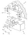
図1を参照すると、管状の部材をハイドロフォームするプレス機械10が表されており、それはラム12、ベッド14(図1に表される部分だけ)、クランプ16の形態の端形成部材及び長尺のシールツール18を備えている。ベッド14の位置は固定されており、ラム12は一般に従来型の制御可能な水圧手段(図示せず)を通じてベッド14と直交する垂直軸に沿った運動に適合している。上部ダイス20がラム12の底部に結合されている。上部ダイスの空洞22(図2)は上部ダイス20内に形成され、ダイス20の長さに延長している。下部ダイス24がベッド14の上部に結合されて上部ダイス20と組み合う。下部ダイス24の内部に下部ダイス空洞26(図2)が形成され、ダイス24の長さに延長している。
【0013】
上部ダイス20が下部ダイス24と組み合うとき、上部空洞22と下部空洞26が長尺の空洞28(図5)を画定して、管状の金属製工作物30を捕捉し相応してそれを形成する。空洞28はしばしば対向する平面状の側部表面を提示することができる。例えばそれは一般に丸みを帯びた角を持つ三角形、不等辺四角形、台形又は矩形の断面を持つことができる、又はそれは例えば円形又は楕円形の閉曲線の断面又はより複雑な閉曲線断面であってもよく、又はそれは直線又は曲線の部分を持つこともでき、それによって同様に構成される最終的なハイドロフォームされる部分を形成する。
【0014】
クランプ16は、1対の対向する側部を持つ実質的に矩形の本体34、上部エッジ36、クランプ16の底部に設置されるクランプ表面38及び側部から側方に延長する1対のウィング40と42を備えている。図示されている例ではクランプ16は、L字形断面のガイドレール46と48を通じて上部ダイス20又はラム12の端面44上に滑動可能に取り付けられる。ガイドレール46と48は、ファスナ50で端面44に固定される。ウィング40と42がガイドレール46、48と端面44の間に滑動可能に受容されて、クランプ16が端面44と同一平面内に又はそれと平行に維持されるとともに、クランプ16はまた長尺の空洞28の長手方向軸を横断する軸に沿ってダイス20に対して移動することもできる。ラム12又はダイス20に対する運動のためにクランプ16を支持する他の配置ももちろん可能である。クランプ16を垂直に移動した位置にバイアスするための手段が提供されて、クランプ16はダイス20の下方に突出する。バイアス手段は例えば気体スプリング又は機械的スプリングを備えている。好ましい形態ではバイアス手段は、流体で動作する例えば空気シリンダ又はより望ましくは水圧シリンダ、及び上部ダイス20又はラム12とクランプ16とのあいだに結合されるピストン装置を備える。例えばシリンダ52はダイス20又は端面44に固定でき、また水圧シリンダ52内で作動するピストンはクランプ16の上部エッジ36に作用するロッド52aを有する。シリンダ52への加圧流体の供給は、上部ダイス20に対するクランプ16の位置を制御する制御手段(図示せず)を通じて調整できる。代わりにシリンダ52を永久的に加圧して、液体をシリンダ52から逃がすリリーフバルブを設置することによって、ダイス20に対するクランプ16の相対的運動に適合させることもできる。クランプ16は垂直に運動するものとして図1と2に表されているが、クランプ16は下部ダイス24又はベッド14に垂直な作用線に沿って、又はラム12の軸に対して傾斜した非垂直の作用線に沿って運動することも可能である。
【0015】
前記の例ではクランプ表面38は、その真下に置かれた下部ダイス24の部分と組み合うようになっている。クランプ表面38内に上端形成空洞54が形成される。図示されている例ではクランプ表面38が下部ダイス24に対して押圧されると、上端形成空洞54とクランプ表面38の真下に置かれた下部ダイスの空洞26の部分によって、管状の工作物30の端部分58を捕捉するための端形成空洞56(図3)が画定される。空洞56は軸方向に長尺の空洞28を持つ平滑な遷移を形成して、空洞28と協働して工作物30の端部分58に対する所望の形状を画定するのが望ましい。その結果端部分58全体をスクラップとして切り取る必要が無くなる。
【0016】
通常は端形成空洞26の横断面形状は一般に、空洞26に隣接する空洞28の少なくとも1部において最終的にハイドロフォームされた部分の形状に対応する長尺の空洞28の横断面形状と組み合いまたそれに類似する。例えば空洞26と28はそれぞれ同じ方向に細長い横断面を有する。さらに空洞26と28は一般に平行な側面を有する。例えば各々は平面状の又は一般的に平面状の対向する面を持ち、空洞26の対向面は一般に空洞28の対向面に平行である。
【0017】
当業者にとって明らかなように、端形成空洞56の下方部分は下部ダイスの空洞26の部分以外の端形成部材によって形成することができる。例えばクランプ16に類似しかつ対向し、また前述したラム12又は上部ダイス20へのクランプ16の取り付けに類似した方法によってベッド14又は下部ダイス24へ垂直運動のために取り付けられる下部クランプ装置の上方部分によって形成することができる。
【0018】
端形成空洞56に各種の形状を持たせることによって管状部材の所要の最終形状を満たすことができる。
【0019】
図1から8に表される例では、長尺のシールツール18はベース60と先細の先端62とを備えている。しかしながら先細の先端62は省くことができる。ツール18はさらに、ベース60から前方に延長するネック64と、ベース60とネック64の間にあるコイニング部分66とを備える。この例ではネック64とベース60はその横断面が、端形成空洞56及び端部分58の所望の最終形状に類似する。所望の最終形状が矩形である図の例ではネック64は、一般に平行な平面状の側壁70、72及び丸いコーナーエッジを通じて接続する面74、76を備える。先細先端62はツール18の先端で開口する流体流ポート78を含み、ネックの前端から滑らかに先細っており、またこの例では円滑に丸みを帯びたエッジを介して互いにまたネック64に接続する一般に平面状の側壁80、82と面84、86を備え、それによって横断面の面積が先端よりもネック64のほうが大きいシールツール18を提供する。先細先端62は、後述するように工作物30内に前進するときに、それを内側から外側に押すことによって工作物30の端部分58を形成するのを支援する。
【0020】
図6に見られるようにコイニング部分66は内部フランク90とコイニングエッジ92を含み、またシールツール18の全周にわたって連続している。コイニング部分66は、ネック64においてベース60に向かって後方外側に傾斜するショルダーを備えることが望ましい。
【0021】
図1と2に見られるシールツール18はさらにベース60内に設置される後部流体流ポート96と、ポート96と78の間に延長する流体通路98(図5)を含む。図1に幾分概略的に表されているようにシールツール18は、ポート96においてバルブVを介しライン99に沿って高圧流体供給源Sに結合される。さらにシールツールは例えば水平に動作し従来型の制御可能な水圧動作ピストンとシリンダ装置(図示せず)のような位置付け手段に結合されるが、それはシールツール18を後退位置(図2)、中間位置(図3)及び前進位置(図7)の間で空洞56の長手方向軸に平行な軸に沿って運動させる。
【0022】
前記のように管状工作物30がハイドロフォームされる場合、管状工作物30の内部に流体、通常は水を充填する必要がある。図1から10に表される例では、流体通路98は比較的狭い。その結果、流体通路98を通る流体の流速は低い。広い通路98を用いることによって、十分に高い流速をそこで得ることができる。しかしながら通路98が狭い場合、充填時間をより短くするために高速充填シュラウド(図示せず)でシールツール18を取り囲んで、管状工作物30の内部への低圧/高流速流体経路を提供することができる。そのようなシュラウドの各々はバルブを通じて、低圧/高流速流体分配手段及びシュラウド内部と連絡する大口径の低圧コンジットを含むことができる。管状工作物30の内部にはまず、シュラウド及び高流速流体分配手段を通じて流体が充填される。管状工作物30内への実質的な充填が終わると、工作物30を各端部分においてシールし、工作物30の内部を低圧分配手段から隔離し、流体通路98を通じて高圧をかけて内部を加圧することによって、ハイドロフォーミングのプロセスが開始される。
【0023】
適切な低圧/高流速充填シュラウドは、水平往復式シュラウドに関するKlagesらによる共通譲渡された米国特許第5,235,836号、及び水平分割ボックスタイプのシュラウドに関するCudiniらによる米国特許第5,445,002号の中で教示されている。これら双方の特許の開示内容を参照することによってここに組み込む。シュラウドの機能には、低圧高流速流体分配手段との内部的連絡、シュラウドの前端部と端形成56の外側端部のあいだの連絡、及びシュラウドとシールツール18のベース60との間で後方への流体の漏洩を防ぐとともに内部でツール18が往復運動するシュラウドの後端部におけるOリングシールが含まれる。シールツール18がシールしながら端部分58内を進むときに、シュラウドと低圧分配手段は工作物30内に生成された高圧から隔離される。水平往復式シュラウドを用いる場合は、シュラウドを位置付け手段に結合して、クランプ16の外側端部、及び例えば下部ダイス24等の端形成空洞の下方部分を画定する部材の外側端部に向かってシュラウドをシールしながら前進させたりそれから後退させたりする。分割ボックスタイプシュラウドを用いる場合はシュラウドは、クランプ16に結合された、及び例えば下部ダイス24等の下方端形成部材又はもしあれば下部クランプにそれぞれ結合された上方部分及び下方部分を備えることができる。これらの部分はともに下端形成部材に対して閉じた位置にシールされる。
【0024】
プレス機械10を用いて管状部材がハイドロフォームされるプロセスの1つの形態をここで説明する。再び図1を参照すると、所望の一般形状に事前屈曲される管状工作物30は下部ダイス24上に置かれ、工作物30の下方部分は、クランプ16の外側の面に隣接して配置された図6の端部エッジ33を持つ下部ダイス空洞26内に配置され、それから水圧手段を起動してラム12を図1の開位置から上部ダイス22が下部ダイス24に極めて接近しているが間隔を置いている部分的に閉じた位置まで移動させる。
【0025】
ラム12の部分閉位置では、上部ダイス20は管状工作物30の外壁から離れて垂直に配置される。しかしながら部分閉位置では、工作物30を上部ダイスと下部ダイス20と24の間で圧縮的に把持することによって、ツール18との反作用による工作物30の長手方向の変位、又はその後の事前加圧を用いる場合はそれによる変形に抵抗する。クランプ16がダイス20に対して永久的に下方にバイアスされていない場合は、この段階でのシリンダ52内の圧力を制御して、図1に見られるようにクランプ16を上部ダイス22の垂直下方に配置することができる。その結果クランプ16は図3と4に見られるように下部ダイス24上で閉じ、管状工作物30の端部分58は端形成空洞56内でクランプされ捕捉される。
【0026】
クランプ16が下部ダイス24とともに閉じる際に、これらの部材は一般に工作物30の端部分58をその初期横断面からハイドロフォームされる部分に所望される最終横断面まで変形する。この横断面は端形成空洞56の横断面に対応する。例えば端部分は、円形から楕円形の横断面に、又はその逆に、又は楕円形又は円形の横断面から一般に小さな半径の丸みを帯びたコーナーを有する正方形、矩形、三角形、不等辺四辺形、台形又は他の多角形の横断面まで変形することができる。もちろん他の様々な横断面も可能である。例えばその横断面は直線部分と曲線部分の双方を含むことができる。重要なことはこの変形される端部分58の形状は単に湾曲した横断面に限定されることはなく、エラストマーシールで容易にシールすることができない線形プロフィールの小半径部分を含む比較的複雑な断面形状であることも可能である。このようにして、エラストマーシールに役立ちまたハイドロフォーム部分の使用前にバリ取りされ捨てられなければならない楕円形、円形又は他の単に湾曲した断面を別々に形成する必要なしに、所望の最終的構成を持つ端部分を含む全長にわたって工作物を形成することが可能になる。所望の端部分が非常に複雑な横断面であるために本発明によってシールできない場合は、本発明のシール手順によってシールされる端部分の横断面を短い遷移部分だけを有する所望の横断面に対応しまたそれに近似するように形成することによって、金属の消耗を無くす又は少なくとも大きく低減できる。
【0027】
クランプ16が図2から図3へと閉じる前に、あいだに、又は後に、ツール18は図3の位置へ前進し、そこで先細部分62とネック64部分が工作物30内に入る。
【0028】
前記の端部分58の変形とは別のクランプ16の機能は、端部分58と摩擦を伴って係合してツール18の工作物30内へのコイニング挿入中にツール18によって引き起こされる軸方向の背分力に抵抗することによって、ツールが工作物内へ前進するとき、特に最初の管の断面と所望の最終製品のそれとのあいだの総体的相違に起因して総体的変形が生じるときに、工作物30がつぶれたり、上部ダイス及び下部ダイス20と24に対して本体方向内側に変位したりすることを防ぐことである。詳細に後述される端部分58のシールとは別のツール18の機能は、不所望の内側への変形に対抗して工作物30を内部で支持することであり、その不所望の変形とは例えばクランプ16がその閉位置(図3)に移動するときに起こり得る長手方向の著しい波打ち又は皺寄りであり、それはやはり特に開始材料の横断面と所望の最終横断面とのあいだの総体的相違の結果として総体的変形が生じる際に、その後の処理において取り除くことが困難のものである。
【0029】
従って、激しい変形が無い場合、例えば開始円形管が楕円形断面の製品に又はその逆に変形される場合、ツール18が無いときはクランプ16を閉じることによって、又は所望であればクランプ16を少なくとも部分的に開いて例えば開位置(図2)に維持しつつツール18を挿入することによって、端部分58を変形することが可能であり、これらの手順の1つは処理時間又はサイクル時間を短縮するのでいくつかの製造工程では望ましいものである。しかしながらいくつかの場合では、前記の高速充填シュラウドの使用によってサイクル時間を短縮できる。
【0030】
図1から8に表されている例では、端部分58を初期円形横断面から最終の一般に矩形の横断面へ変形し、またこの変形のあいだ工作物30を内部的又は外部的に支持することが望ましい。図1から8の例では一般にクランプ16を開位置(図2)から閉位置(図3)まで閉じるあいだ、位置付け手段を起動してシールツール18を、長尺の端形成空洞28と56の長手方向軸に平行な軸に沿って工作物30の端部分58の方向へ前進させる。シールツール18が図2の位置から図3の位置まっで進む際に、その先細先端62とネック64が工作物30の内部領域88に入って、管状工作物30の外壁に対してクランプ16と下部ダイス24により及ぼされる内側横方向の圧力によって端部分58が変形され始める。シールツール18の前進により引き起こされる管状工作物30の軸方向移動のいかなる傾向も、クランプ16、下部ダイス24及び工作物30の外壁のあいだの摩擦によって抵抗を受ける。
【0031】
クランプ16の閉じ及びシールツール18の前進は、端部分58の形状が端形成空洞56の形状に類似し、またベース部分90に隣接するネック64の横断面に類似するまで続けられる。すなわちこれらのエレメントは、大きさが異なるが同じ形状であるという点で類似している。前記の例では図13と14に表されるこの点は変形工程の終了を意味し、それは上部クランプ表面38が下部プレス表面24に接したときに達成される。
【0032】
前記の例では、変形工程のあいだ端部分58がゼロ伸張であることが望まれる場合、ネック部分64の外周を開始材料管30の内周に等しいか又はわずかに小さくすべきである。ネック部分の表面と変形される端部分58の内壁とのあいだには少なくとも約0.001インチ(約0.03mm)のクリアランスがあるのが望ましい。端形成空洞56の内周は、開始管30の公称外周に等しいのが望ましい。一般に開始材料管の外径における公差は考慮されない。壁の厚さに関して、一般に装置のディメンジョンは工作物の最小壁厚に基づく。一般的に壁厚の公差は製造業者によって正の値だけ、例えば−0.0+0.008インチとして指定されており、そのような場合に設計は公称壁厚に基づく。製造業者の公差は通常は比較的小さく、端部分58の小さな変形によって調整することができる。工作物30の外部ディメンジョンが公称値よりも大きい場合は、クランプ16と下部ダイス24等の下方部材が端部分58をわずかに圧縮し、それらが閉じたときにそれを公称ディメンジョンに一致させる。内部ディメンジョンが公称値よりも小さい場合は、シールツール18が挿入されるときに工作物をわずかに伸張させて、工作物30を公称内部ディメンジョンに一致させる。従って通常は、設計は開始管工作物30の公称外部ディメンジョンと最小壁厚に基づく。
【0033】
高速充填シュラウドが変形工程の終わりで用いられる場合、管状工作物30から及び高速充填シュラウドに関してシールツール18を部分的に後退させて、管状工作物30の内壁31とシールツール18との間に通路を作る。それから低圧コンジットとシュラウドを通じて低圧/高流速流体分配手段から管30の内部領域88に流体が急速に充填される。シュラウドの後端におけるOリングシールによって、シュラウドとシールツール18のベース60のあいだで低圧流体が後方に漏洩するのを防止する。ここで管状工作物30の対向端が、図1から8を参照して前述されたものに類似のシールツール及びクランプ装置によって、又は当業者に周知のタイプのプラグ手段によってシールされる。
【0034】
管状工作物30に流体が充填された後、コイニング及びシール工程を実行してシールツール18を工作物30の端部分58にシールする。シール工程のあいだ、シリンダ52に圧力を加えつづけてクランプ16によって与えられる側方の圧力を維持し、コイニングエッジ92が工作物30の端33を押すまでシールツール18を工作物30に向けて進める。
【0035】
図5から8に表される実施形態では、ツール18の内部フランク90とコイニングエッジ92間の間隔は管状工作物30のへ気圧よりも小さいのが望ましく、またそれは管の最小壁厚に基づいて変形された管状工作物30の壁厚のたかだか約75%であるのが望ましい。
【0036】
それからシールツール18の位置付け手段を起動してツール18を端33を通り越してわずかの距離端部分58内にプレスすることによって、コイニング部分は工作物30の端部分58の短いセクションを厚くすることによりコイニングする。この工程は図7と8に表されている。コイニングエッジ92の後方のベース部分60の幅は、コイニング動作が工作物30の変形される端部分58の壁厚を減少するように設定される。コイニング部分66はツール18の外周で連続し、また工作物30の内壁31は第2空洞56の内壁との反作用によってシールツール18のベース60とネック64に対してプレスされているので、そのコイニング動作によってツール18と工作物30間に強い圧縮作用が存在する内壁31の周りに連続的なショルダが形成され、それによって端部分58とシールツール18間に耐漏洩の端シールを実現し、その後の工作物30内の内部圧力に耐えることが可能になる。ツール18をシール位置に保持するために、またツール18を外側に変位させようとする内部流体圧力に抵抗するために、ロック手段をツールに設置してもよい。そのようなロック手段は例えば、横方向に挿入されてツール18と係合しそれをわずかに内部に押して工作物のコイニングとシールを完成させる楔を備えることができる。その楔は後退しようとするどのような傾向をも阻止する。代わりに、共通譲渡された(Klagesらによる)米国特許第5,235,836号に開示されている逆転防止手段又はブロックをツール18に設置することもできる。これに関して米国特許第5,235,836号の開示を参照することによってここに組み込む。
【0037】
コイニング工程によって工作物30の壁厚を少なくとも0.0001インチから約0.050インチ(約0.003から約1.3mm)減少させるのが望ましい。壁厚の減少が約0.0001インチより小さい場合は、コイニングされる工作物30とツール18間の弾性抗力が不十分であるために完全に耐漏洩的なシールは達成されない。壁厚の減少が約0.050インチよりも大きい場合は、エネルギーの過剰な消費が必要とされ、装置を過度の機械的ストレス下に置きまたクランプ16が対抗することのできない軸方向のスラストを及ぼすために、工作物はクランプ16を通って押される又はそれに対して軸方向に変位させられかねない。さらにツール18の磨耗速度が過剰に大きくなりかねない。コイニングによる壁厚の減少が約0.0015〜約0.015インチ(約0.04〜0.4mm)であればより望ましく、さらに約0.002〜0.011インチ(約0.05〜0.33mm)であればなお望ましい。
【0038】
単一の工程においてネック部分74からベース部分60まで延長するコイニング位置を有する代わりに、ツール18は複数の工程を備えるコイニング部分を有することによって、工作物の内部をコイニングして複数の工程でそれを形成することができる。その場合前述された壁厚の望ましい減少は、ネック部分74とベース部分60間でこれらの工程によって及ぼされる壁厚のすべての減少の総計又は合計を参考にする。
【0039】
ベース部分60のディメンジョンを選択する場合、一般に工作物30の壁厚の公差を考慮することによって十分な気密性をもつシールを与える壁厚の所望の減少を達成できる。例えば端形成空洞56の幅が2インチ(50.8mm)であり、最初の壁厚が0.060インチ(1.524mm)でその公差が−0.0+0.008インチ(−0.0+0.2032mm)である場合、ベース部分60は1.86インチ(47.9044mm)の幅を持つので、コイニング動作によって壁は0.003〜0.011インチ(0.0762〜0.2794mm)薄くなる。
【0040】
コイニング工程及びシール工程ではツール18は工作物30と直接金属同士の接触状態にあり、従ってエラストマーシールと結びついた問題及び限界を回避することができることに注意されたい。ツール18の磨耗速度を低減するために、それはいかなる従来型の硬化方法によって硬化させてもよい。
【0041】
コイニング及び端シール動作のあいだ、及び下部ダイス24状のダイス20を完全に閉じる工程のあいだ、クランプ16が上方に押し上げられようとするのに対抗するに十分な圧力がシリンダ52内で維持される。例えば圧力開放バルブをシリンダ52に接続して所望の圧力を維持しつつ、コイニング動作及びダイスを閉じる動作に適合させるとともにクランプ16を下部ダイス24に対して強固にプレスするのに十分な流体を排出するようにバルブを設定することができる。
【0042】
必要又は所望であれば、それから流体入口ポート96を高圧供給源に接続することによって工作物30の内部の事前加圧を行う。この事前加圧は最終ハイドロフォーム圧力よりも小さく、またその手順と長所は共通譲渡された(Cudiniによる)米国特許第Re.33,990号の中でより詳細に説明されており、その開示内容を参照することによりここに組み込む。要約すればこの事前加圧によって、複雑に構成された又は幾分小さな断面のダイス空洞内に工作物30を受容することが可能になるとともに、例えば長尺の空洞28の外部の上部ダイス20と下部ダイス24の間で工作物30を締め付けることによる不所望の又は有害な変形の問題を取り除くことが可能になる。一旦事前加圧が行われると、又は事前加圧が行われない場合にはコイニング及び端シール動作のすぐ後に、ラム12を作動させて上部ダイス20を下げそれを下部ダイス24上で完全に閉じて、工作物30を上部ダイス空洞22と下部ダイス空洞26内で捕捉する。ポート96を通じて高圧を加えて工作物30をハイドロフォームする、すなわち空洞28の内壁に密着して一致させ、そこで空洞28の内壁が内側にプレスして工作物の最終形状を画定する。その結果開始材料の管状工作物30の外周が約ゼロから約100%まで伸張する。事前加圧工程が用いられていればそのあいだ、及びハイドロフィーム工程のあいだ、軸方向外向きのスラストに対抗するのに十分な位置付け手段を通じて、ツール18に対する軸方向内向きの圧力が維持される。
【0043】
それから高圧が解放され、ツール18が図2の位置まで後退し、往復高速充填シュラウドが在ればそれが後退し、ラム12とクランプ16が図2の位置まで持ち上げられて、ハイドロフォームされた工作物は装置から出ることが可能になる。それから新たな管状工作物30が下部ダイス24上に置かれて、前記の動作サイクルが繰り返される。
【0044】
高速充填シュラウドが無い場合は、ハイドロフォームサイクルの完了までツール18を工作物30から後退させる必要なしに、端シール後の工作物に通路98を通じて充填及び加圧が行われる。
【0045】
クランプ16が閉じられる前にツール18が図3の位置まで導入される場合は、高速充填が用いられていればその前に、又は高速充填シュラウドが用いられていなければコイニング及び端シールの前に、クランプ16が閉じられることを除いて前記の手順の通りにする。
【0046】
ツール18が挿入される前にクランプ16が閉じられる場合は、ツール18が後退しているあいだの高速充填(それを用いていれば)によって前記の手順を変更でき、又は高速充填を用いていなければコイニングして管を端シールし通路を通じて充填することによって前記の手順を変更できる。
【0047】
周知のように、ラム12の動作の制御、ツール18の後退及び前進の制御、シリンダ52の加圧したがってクランプ16の運動の制御、往復高速充填シュラウドがあればその制御、高速充填シュラウド及び通路98に接続する高圧供給源に結合されたバルブの制御は手動で行うことができるが、通常はタイミングサイクルに従って動作する従来型制御手段によって自動的に行われる。
【0048】
もちろん前記の内容に対する様々な修正が可能である。例えばシールツール18は工作物30の端部分58を伸張してもよい。その場合、ツール18のネック部分64の外周が工作物30の内壁よりもかなり例えば20%まで大きいという点で、またクランプ16と下部ダイス24によって画定される端形成空洞56又は他の端形成空洞のディメンジョンは、それらが工作物30の伸張した端部分の外部をぴったりと受容するように設定されるという点で、前記の手順が修正される。ツール18のネック部分64の挿入による工作物の端部分の伸張工程のあいだに引き起こされる軸方向のスラストに抵抗するために、工作物30の対向端を把持してもよい又はその移動を例えば当接部材で対抗することによって防止してもよい、又は類似の伸張ツール18を工作物30の対向端内に同時に挿入してもよい、又は工作物30の中間部分を部分的に閉じた位置にある上部及び下部ダイス20と24のあいだで把持してもよい。
【0049】
別の変形例では図9と10に見られるシールツール218を用いることができる。シールツール218はシールツール18に類似しており、同様の部品は同様の参照番号に200を加えて表される。しかしながらシールツール18とは逆に、内部フランク部分290とコイニングエッジ292との間の間隔は管状工作物30の壁厚よりもわずかに小さいのが望ましく、またベース部分260の幅は変形される端部分58の端面をツール218がコイニングするように設定されるのが望ましい。
【0050】
シールツール218を用いる手順は、それが端部分58の端33内に十分にプレスされることによってコイニングエッジ292が端部分58の端面33だけをコイニングするコイニング工程を除いて、ツール18を参照して前述されたものと同様である。この工程は図9と10に表されている。これによって内部張り出しシールが形成されるが、そこでは管30の端面が不均一に変形され薄くされてそれに角度付き面33aを与え、また部分290と292間に延長するコイニング部分と傾斜面33aの間のシールを形成する。手順の残余はツール18に関して前述されたものと同様である。
【0051】
図11はさらなる修正例を表しているがそこでシールツール318は、変形される端部分58の内部幅よりも幾分大きく外部幅よりも小さい幅のベース部分316と、コイニングエッジ392から内側に先細るネック部分364とを有している。端形成部材、例えばクランプ16に類似した上部クランプ、又は下部クランプ、又は株ダイス24の端形成部分は図示されるように、ベース部分316の外側部及び変形される端部分58の軸に平行に延長する内側部326と、内側部326から横断的に外側に延長する端部分327とを有している。変形される端部分の外側部が端形成部材によって係合され、またツール318が変形端部分58内に軸方向内向きに強くプレスされるコイニング及びシール工程では、図11に見られるように端部分18の壁は端部分327から軸方向後ろにわずかに張り出して、コイニングエッジ392と内側部326の間で挟まれて薄くなる。
【0052】
図1から10を参照して前述されたシールツール18と218は、変形工程のあいだネック64と264が工作物30の端部分58をその全内壁31に沿って支持することによって工作物30を内部的に支持する。従ってシールツール18と218は、工作物30に対する非常に難しい変形が必要とされる応用例に対して有益である。しかしながら先細先端62と262は一般的に平面状の側壁と面を含むので、高速充填が用いられる場合は変形工程の終わりでシールツール18又は218は、ツール18又は218と工作物30のあいだの内部に流体が流入するように工作物30から後退しなければならない。この後退工程によって、最終管状部材を作成するのに要する時間が増大する。
【0053】
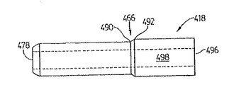
工作物30のより高速の充填を可能にするために、修正されたシールツール418(図12と13)を用いることができる。シールツール418はシールツール18に類似しており、それはベース460、先細先端462、ベース460と先細先端462間に延長するネック464、ベース460とネック464間に位置付けられて内部フランク部分490とコイニングエッジ492を含む連続的コイニング部分466、先細先端462内に設置された流体流ポート478、ベース460内に設置された流体入口ポート496、及び流体ポート496と478間に延長する流体通路498を備える。しかしながらシールツール18とは異なってネック464は短くされ、また先細先端462はシールツール418の先端からネック464まで延長する1対の対向する凹状の側壁480と482を有して、先端近傍からネック464近傍に向けて次第に大きくなる横断面の面積をシールツール418に与える。
【0054】
使用に際しては、工作物30をプレス機械内に置いた後に、クランプ16と下部ダイス24等の端形成部材で一緒に閉じる工程の間にツール418が工作物30内に挿入されるのが望ましい。工作物30の対向端がシールされる。それから外部の高速充填シュラウドを通じて高速充填が開始される。最初はツール418は、ほぼ図5に表される程度まで挿入され、ネック464は工作物30の中に入らない。工作物30の端と各側壁480間にギャップがあるので、工作物はこれらのギャップを通じて高速充填でき、またそれが望ましい。それからツール418を図7に表される程度まで挿入し、工作物の端をコイニングしてシールする。それから一般に図1から8を参照して上に詳述された方法によって事前加圧、ダイスの閉じ、及びハイドロフォームを行うことができる。ツール418の最初の挿入の間、先細先端462は変形される端部分58を内部から機械的に平滑化して不所望の波打ち又はギザギザを取り除くが、それが取り除かれない場合は端形成部材を閉じる間に端部分の内部に導入されて、内部的流体圧力だけでは取り除くことが困難になりかねない。図12と13のツール418は高速充填を行うための後退工程を必要としないために図1から8のツール18よりもより短い処理サイクルを可能にするので、一般的にツール18よりも望ましい。
【0055】
図14と15を参照すると、ツール418に幾分類似したシールツール518が表されている。同じ部品は同じ参照番号に100を加算して表される。しかしながらこの場合、内部フランク部分590とコイニングエッジ592間の間隔は工作物30の壁厚よりもわずかに小さく、またシールツール518は高速充填工程を完成するために工作物30から後退する必要が無いという点を除いて、ツール418はツール218に関して前述された方法で用いることができる。
【0056】
本発明は好ましい実施形態の説明に制限されないことを理解されたい。当業者は添付のクレームによって定められる本発明の精神と範囲から逸脱することなしに、開示された実施形態に対していくらかの追加、削除及び/又は修正を行うことができる。
【図面の簡単な説明】
【図1】 ラム、ベッド、クランプ、シールツール及び管状工作物を示す、本発明によるハイドロフォームプレス機械を部分的に略式に示す部分斜視図である。
【図2】 ハイドロフォームプレス機械の端部分を長手方向断面図である。
【図3】 変形工程の最後における図2に対応する図である。
【図4】 変形工程の最後におけるハイドロフォームプレス機械の部分的に断面で示す前面図である。
【図5】 シール動作の初期工程を示す、図1に示すシールツールの長手方向断面図である。
【図6】 図5に示すシールツールのコイニング部分の拡大図である。
【図7】 シール動作における後半の段階を示す長手方向断面図である。
【図8】 図7に示すシールツールのコイニング部分の拡大図である。
【図9】 図7に対応しており、また、修正されたシールツールの使用法を示す長手方向断面図である。
【図10】 図9に示すシールツールのコイニング部分の拡大図である。
【図11】 さらに修正されたシールツールとクランプ装置の使用法を示す図6に類似の拡大図である。
【図12】 シールツールのさらなる修正形態の上面図である。
【図13】 図12に示すツールの側面図である。
【図14】 シールツールのさらなる修正形態の上面図である。
【図15】 図14に示すツールの側面図である。[0001]
The present invention relates to a method and an apparatus used in the field of hydroforming a tubular member, although not limited thereto. More particularly, the present invention relates to a method and apparatus for sealing the end of a hydroformed tube.
[0002]
Hydroform processes are applied in various manufacturing fields, and are formed to have very accurate dimensions, for example, in the automobile manufacturing industry, aircraft industry and furniture manufacturing industry, and usually have strength and light weight. It has also been applied to industrial processes for producing parts used in other industries where tubular products are desired.
[0003]
A conventional hydrofoam press apparatus is taught by Bowman et al. In US Pat. No. 5,223,854. However, such a pressing device has the disadvantage that the burrs at the edges of the disclosed material tube damage the O-ring used for sealing purposes, which can lead to leakage of the sealing unit. Second, the portion of the starting tube material that extends from the end of the die does not always form part of the finished product, and therefore must be deburred as scrap material. As a result, manufacturing costs increase both in terms of additional material costs and the time and equipment required to deburst excess material.
[0004]
US Pat. No. 5,235,836 to Klages et al. Teaches a tube extension seal head having an elastomeric ring that is protected from burr damage. However, like the Bowman patent, the sealable portion of the tube extending adjacent to this seal head does not fit the desired shape of the hydroformed end product and is therefore generally deburred as scrap. There must be. In addition, the elastomeric ring must be replaced periodically, which increases manufacturing costs.
[0005]
U.S. Pat. No. 4,761,982 to Snyder teaches a method and apparatus for forming a tube that eliminates the need for an elastomeric ring. In the Snyder patent, a large overhanging bell section is formed at each end of the tube that typically must be deburred as scrap.
[0006]
US Pat. No. 5,475,911 to Wells et al. Also describes a hydroforming tool that eliminates the need for an elastomeric ring and provides a significant outward overhang on the outer wall of the workpiece. However, unless it is desirable to project outward the outer walls at both ends of the workpiece, both ends of the workpiece must be deburred as scrap.
[0007]
Therefore, it can be applied to the end of the workpiece without the need to use an elastomeric ring, and can be adjusted to fit the desired shape of the end portion of the workpiece, and also the net product of the final product. Seals that eliminate or minimize the amount of scrap material that must be deburred from both ends of the workpiece for a wide range of end shapes There remains a need for equipment.
[0008]
The first embodiment of the present invention requires an elastomeric ring by mechanically aligning the end of the tubular workpiece to the desired shape of the end of the hydroformed end product or as close as possible And a method and apparatus for sealing the end of the workpiece.
[0009]
A first aspect of the invention provides a method for sealing an end of a tubular workpiece having an initial transverse cross section, wall thickness, inner surface, inner region bounded by the inner surface and a pair of opposing ends. Is:
Providing a sealing tool including a neck and a coining portion including a shoulder extending outwardly from the neck;
Deforming one of the opposing ends to a deformed end portion having a modified transverse cross-section different from the initial transverse cross-section;
Pressing the sealing tool axially into the deformed end portion while pressing the one opposing end laterally inwardly, thereby sealing the deformed end portion;
Is included.
[0010]
A further aspect of the invention provides an apparatus for sealing an end of a tubular workpiece having an initial transverse cross section, a longitudinal axis, a wall thickness, an inner surface, an inner region bounded by the inner surface and a pair of opposing ends. The device:
A sealing tool including a neck and a coining portion, wherein the coining portion includes a shoulder extending outwardly from the neck;
An end forming member including a cavity disposed transversely to the longitudinal axis and having a transverse cross section different from the initial transverse cross section;
First positioning means coupled to the sealing tool moved through the tool along an axis parallel to the longitudinal axis and performing a sealing process;
Second positioning means coupled to the end forming member for performing a deformation step;
With
The deforming step presses the end forming member laterally inward toward one of the opposing ends to define a deformed end portion having a deformed transverse cross-section different from the initial cross-section. And the step of sealing coins the workpiece by pressing a sealing tool axially into the deformed end portion while pressing the deformed end portion laterally inward. including.
[0011]
Preferred embodiments of the present invention will now be described with reference to the following drawings, in which like reference numerals indicate like parts.
[0012]
Referring to FIG. 1, a
[0013]
When the
[0014]
The
[0015]
In the above example, the clamping
[0016]
Typically, the cross-sectional shape of the end forming cavity 26 is generally combined with the cross-sectional shape of the
[0017]
As will be apparent to those skilled in the art, the lower portion of the
[0018]
By providing the
[0019]
In the example represented in FIGS. 1 to 8, the
[0020]
As seen in FIG. 6, the coining
[0021]
The
[0022]
When the
[0023]
Suitable low pressure / high flow rate filling shrouds are commonly assigned U.S. Pat. No. 5,235,836 to Klages et al. For horizontal reciprocating shrouds and U.S. Pat. No. 5,445 to Cudini et al. For horizontal split box type shrouds. Taught in 002. The disclosures of both of these patents are incorporated herein by reference. The function of the shroud includes internal communication with the low pressure, high flow rate fluid distribution means, communication between the front end of the shroud and the outer end of the
[0024]
One form of process in which the tubular member is hydroformed using the
[0025]
In the partially closed position of the
[0026]
As the
[0027]
Before, during, or after the
[0028]
The function of the
[0029]
Thus, if there is no severe deformation, for example if the starting circular tube is deformed to an oval cross-section product or vice versa, by closing the
[0030]
In the example represented in FIGS. 1 to 8, the
[0031]
Closing of the
[0032]
In the above example, if it is desired that the
[0033]
If a fast-fill shroud is used at the end of the deformation process, the
[0034]
After the
[0035]
In the embodiment represented in FIGS. 5-8, the spacing between the
[0036]
The coining portion is then made thicker by shortening the short section of the
[0037]
It is desirable to reduce the wall thickness of the
[0038]
Instead of having a coining position that extends from the
[0039]
When selecting the dimensions of the
[0040]
It should be noted that in the coining and sealing process, the
[0041]
Sufficient pressure is maintained in the
[0042]
If necessary or desired, pre-pressurization of the interior of the
[0043]
The high pressure is then released, the
[0044]
In the absence of a fast fill shroud, the end-sealed workpiece is filled and pressurized through
[0045]
If the
[0046]
If the
[0047]
As is well known, control of
[0048]
Of course, various modifications to the above contents are possible. For example, the sealing
[0049]
In another variation, the
[0050]
The procedure using the
[0051]
FIG. 11 shows a further modification where the
[0052]
The
[0053]
A modified sealing tool 418 (FIGS. 12 and 13) can be used to allow faster filling of the
[0054]
In use, the
[0055]
Referring to FIGS. 14 and 15, a
[0056]
It should be understood that the invention is not limited to the description of the preferred embodiments. Those skilled in the art can make some additions, deletions and / or modifications to the disclosed embodiments without departing from the spirit and scope of the present invention as defined by the appended claims.
[Brief description of the drawings]
FIG. 1 is a partial perspective view, partially in schematic form, of a hydroform press machine according to the present invention showing a ram, bed, clamp, sealing tool and tubular workpiece.
FIG. 2 is a longitudinal sectional view of an end portion of a hydroform press machine.
FIG. 3 is a view corresponding to FIG. 2 at the end of the deformation process.
FIG. 4 is a front view, partly in section, of the hydroform press machine at the end of the deformation process.
FIG. 5 is a longitudinal sectional view of the sealing tool shown in FIG. 1 showing an initial step of the sealing operation.
6 is an enlarged view of a coining portion of the sealing tool shown in FIG.
FIG. 7 is a longitudinal sectional view showing the latter half of the sealing operation.
8 is an enlarged view of a coining portion of the sealing tool shown in FIG.
FIG. 9 is a longitudinal cross-sectional view corresponding to FIG. 7 and illustrating the use of a modified sealing tool.
10 is an enlarged view of a coining portion of the sealing tool shown in FIG.
FIG. 11 is an enlarged view similar to FIG. 6 showing the use of a further modified sealing tool and clamping device.
FIG. 12 is a top view of a further modification of the sealing tool.
13 is a side view of the tool shown in FIG.
FIG. 14 is a top view of a further modification of the sealing tool.
15 is a side view of the tool shown in FIG.
Claims (34)
ネックと、前記ネックから外向きに延長するショルダを含むコイニング部分と、を含むシールツールを提供する工程と;
前記対向端の内の一方を変形して、前記初期横断方向断面とは異なった変形した横断方向断面を有する変形端部分とする工程と;
前記一方の対向端を横方向内向きにプレスしながら前記シールツールを前記変形端部分にプレスすることによって前記工作物をコイニングし、これによって、前記変形端部分をシールする、コイニング工程と;
を含み、
前記シールツールが、前記変形横断方向断面の内部横断方向幅より大きい横断方向幅を持つ前記コイニング部分の後方にあるベース部分を含み、
前記コイニング工程が、前記ベース部分を前記一方の対向端の前記端表面から軸方向外向きに維持しながら、前記一方の対向端の端表面を前記ショルダと係合させる工程を含む、
管状工作物の端をシールする方法。In a method of sealing an end of a tubular workpiece having an initial transverse cross section, a wall thickness, an inner surface, an inner region bounded by the inner surface, and a pair of opposing ends, the method includes:
Providing a sealing tool including a neck and a coining portion including a shoulder extending outwardly from the neck;
Deforming one of the opposing ends to form a deformed end portion having a deformed transverse cross-section different from the initial transverse cross-section;
Coining the workpiece by pressing the sealing tool onto the deformed end portion while pressing the one opposing end inwardly in the transverse direction, thereby sealing the deformed end portion;
Including
The sealing tool includes a base portion behind the coining portion having a transverse width that is greater than an internal transverse width of the deformed transverse section;
The coining step, while maintaining said base portion from said end surface of said one of the opposite ends in the axial direction outwardly, includes the step of the end surface of said one of the opposing end engaged the shoulder and engaged,
A method for sealing the end of a tubular workpiece.
(b)後出の管状工作物の長手方向軸に対して横断方向に初期断面を有する端部分を有する管状工作物を提供する工程と;
(c)前記管状ブランクの端部分を変形して、前記初期断面とか異なった前記管状ブランクの長手方向軸に対して横断方向に変形済み断面を有する変形済み端部分を前記端部分に与える工程と;
(d)ネック及び前記ネックから外向きに延長するショルダを含むコイニング部分を含むシールツールを、前記変形済み端部分に取り付けることによって前記ブランクをシールし、また、前記端部分を横方向内向きにプレスしながら前記シールツールを軸方向にプレスすることによって前記工作物を前記変形済み端部分にコイニングする工程と;
を含み、
前記ダイス提供工程において、前記ダイスが開いた中間位置と閉じた位置との間を移動するダイスセクションを含み、ダイスセクションの各々が、ダイス空洞部分及びそれと組み合う表面部分とを有し、前記閉じた位置において、ダイスセクションは、各セクションの前記組み合い表面が各隣接したセクションの前記組み合い表面部分と組み合い係合状態にあり、また、前記管状ブランクの前記端部分を変形する前記工程が、前記開いた位置にある前記ダイスセクション同士間に前記ブランクを置く工程と、前記ダイスセクションを前記中間位置まで部分的に閉じて前記端部分を変形する工程と、を含み、また、前記ダイスセクションが前記閉じた位置に移動される前に前記シールツールが前記変形済み端中に挿入され、
前記ダイス提供工程において、少なくとも1つのダイスセクションが、自身に対して可動に接続されたクランプ部材を有し、前記クランプ部材が、少なくとも1つの他の端形成部材と共に、前記変形済み断面プロフィールを有するスロート空洞を画定し、前記クランプ部材が、前記他の端形成部材に向けてバイアスされ、前記1つのダイスセクションが前記開いた位置から前記中間位置に移動すると前記工作物の前記端部分をクランプして変形し、次に前記1つのダイスセクションに関して縮み、さらにまた、前記ダイスセクションが前記中間位置から前記閉じた位置に移動すると前記他のダイスセクションに関して実質的に停止状態に留まる、
管状工作物の端をシールする方法。(A) providing a die;
(B) providing a tubular workpiece having an end portion having an initial cross section transverse to the longitudinal axis of the subsequent tubular workpiece;
(C) deforming an end portion of the tubular blank to provide the end portion with a deformed end portion having a deformed cross section transverse to the longitudinal axis of the tubular blank different from the initial cross section; ;
(D) sealing the blank by attaching a sealing tool including a neck and a coining portion including a shoulder extending outwardly from the neck to the deformed end portion; Coining the workpiece onto the deformed end portion by pressing the sealing tool axially while pressing;
Including
In the step of providing a die, the die includes a die section that moves between an open intermediate position and a closed position, each of the die sections having a die cavity portion and a surface portion that mates with the die section; In position, the die section is in mating engagement with the mating surface portion of each adjacent section with the mating surface portion of each adjacent section, and the step of deforming the end portion of the tubular blank is opened. Placing the blank between the die sections in position and partially closing the die section to the intermediate position to deform the end portion, and the die section is closed The sealing tool is inserted into the deformed end before being moved into position,
In the die providing step, at least one die section has a clamp member movably connected thereto, and the clamp member has the deformed cross-sectional profile along with at least one other end forming member. Defining a throat cavity, the clamping member being biased toward the other end forming member, and clamping the end portion of the workpiece when the one die section is moved from the open position to the intermediate position. And then shrink with respect to the one die section, and still remain substantially stationary with respect to the other die section as the die section moves from the intermediate position to the closed position.
A method for sealing the end of a tubular workpiece.
前記長手方向軸に対して横断方向に配置され、また、前記初期横断方向断面とは異なった横断方向断面を有する空洞を含む端形成部材と;
前記シールツールにカップリングされており、前記長手方向軸に平行な軸に沿って前記シールツールを移動させ、また、シール工程を実行する第1の位置付け手段と;
前記端形成部材と結合しており、変形工程を実行する第2の位置付け手段と;
を含み、
前記変形工程が、前記対向端の内の一方に向けて前記端形成部材を横方向内向きにプレスして、前記初期断面とは異なった変形した横断方向断面を有する変形済み端部分を画定する工程を含み、前記シール工程が、前記変形済み端部分をプレスしながら前記シールツールを軸方向にプレスすることによって前記変形済み端部分に前記工作物をコイニングする工程を含む、装置。In an apparatus for sealing an end of a tubular workpiece having an initial transverse section, a longitudinal axis, a wall thickness, an inner surface, an inner region bounded by the inner surface, and a pair of opposing ends. The apparatus is: a sealing tool including a neck and a coining portion, wherein the coining portion includes a shoulder extending outwardly from the neck;
An end forming member including a cavity disposed transversely to the longitudinal axis and having a transverse cross section different from the initial transverse cross section;
First positioning means coupled to the sealing tool, for moving the sealing tool along an axis parallel to the longitudinal axis, and for performing a sealing process;
Second positioning means coupled to the end forming member and performing a deformation step;
Including
The deforming step presses the end forming member laterally inward toward one of the opposing ends to define a deformed end portion having a deformed transverse cross-section different from the initial cross-section. And the step of sealing includes coining the workpiece onto the deformed end portion by pressing the sealing tool axially while pressing the deformed end portion.
前記ラムにカップリングされた第1のダイスと;
前記ベッドにカップリングされ、また、前記第1のダイスと共に管状工作物を捕獲する前記所望の形状を有する第1の空洞を画定する第2のダイスであり、前記工作物が長手方向軸と、壁厚と、内面と、前記内面画境界となっている内部領域と、対を成す対向端と、を有する、第2のダイスと;
流体流ポートを含むネックと、前記ネックから外向きに延長するショルダを含むコイニング部分と、を含むシールツールと;
前記長手方向軸に対して横断方向に配置され、また、前記所望の形状にほぼ適合する横断方向断面を持つ第2の空洞をさらなる端形成部材と共に画定する第2の部分的空洞を画定するクランプ部材と;
前記シールツールにカップリングされ、前記長手方向軸に平行な軸に沿って前記シールツールを移動させる第1の位置付け手段と;
前記流体流ポートに接続可能な加圧流体分配手段と;
前記クランプ手段に結合され、変形工程とシール工程を実行する第2の位置付け手段であり、前記閉経工程が、前記対向端の内の一方に向けて前記クランプ部材を横方向内向きにプレスして、前記所望の形状に類似した前記横断方向断面を有する変形済み端部分を形成する工程を含み、前記シール工程が、前記クランプ部材で前記端部分を横断方向内向きにプレスしながら前記シーツルーツを軸方向にプレスすることによって前記工作物を前記変形済み端部分にコイニングする工程を含み、これによって、前記シール工程の後で、前記管状工作物が、前記流れポートを介して前記分配手段から流体を分配することによって加圧されて、前記第1と第2のダイスを閉じた後で前記所望の形状に形成される、第2の位置付け手段と;
を備えるプレス機械。A press machine for forming a tubular member having a desired transverse cross-sectional shape, the press machine comprising: a ram and a bed arranged in movable relation to each other;
A first die coupled to the ram;
A second die coupled to the bed and defining a first cavity having the desired shape for capturing a tubular workpiece together with the first die, the workpiece comprising a longitudinal axis; A second die having a wall thickness, an inner surface, an inner region defining the inner surface border, and a pair of opposing ends;
A sealing tool including a neck including a fluid flow port and a coining portion including a shoulder extending outwardly from the neck;
Clamp defining a second partial cavity disposed transversely to the longitudinal axis and defining a second cavity with a further end forming member having a transverse cross section generally conforming to the desired shape With members;
First positioning means coupled to the sealing tool and moving the sealing tool along an axis parallel to the longitudinal axis;
Pressurized fluid dispensing means connectable to the fluid flow port;
A second positioning means coupled to the clamping means for performing a deformation process and a sealing process, wherein the menopause process presses the clamping member laterally inward toward one of the opposing ends; Forming a deformed end portion having the transverse cross-section similar to the desired shape, the sealing step pressing the end roots inward in the transverse direction with the clamping member. Coining the workpiece to the deformed end portion by axially pressing so that, after the sealing step, the tubular workpiece is fluidized from the dispensing means via the flow port. Second positioning means that is pressurized by dispensing and formed into the desired shape after closing the first and second dies;
Press machine.
Applications Claiming Priority (3)
| Application Number | Priority Date | Filing Date | Title |
|---|---|---|---|
| US09/249,764 US6279364B1 (en) | 1999-02-16 | 1999-02-16 | Sealing method and press apparatus |
| US09/249,764 | 1999-02-16 | ||
| PCT/GB2000/000364 WO2000048761A1 (en) | 1999-02-16 | 2000-02-08 | Sealing method and press apparatus |
Related Child Applications (1)
| Application Number | Title | Priority Date | Filing Date |
|---|---|---|---|
| JP2010223422A Division JP2011045930A (en) | 1999-02-16 | 2010-10-01 | Sealing method and pressing device |
Publications (2)
| Publication Number | Publication Date |
|---|---|
| JP2002537118A JP2002537118A (en) | 2002-11-05 |
| JP4704568B2 true JP4704568B2 (en) | 2011-06-15 |
Family
ID=22944891
Family Applications (2)
| Application Number | Title | Priority Date | Filing Date |
|---|---|---|---|
| JP2000599532A Expired - Lifetime JP4704568B2 (en) | 1999-02-16 | 2000-02-08 | Sealing method and press machine |
| JP2010223422A Pending JP2011045930A (en) | 1999-02-16 | 2010-10-01 | Sealing method and pressing device |
Family Applications After (1)
| Application Number | Title | Priority Date | Filing Date |
|---|---|---|---|
| JP2010223422A Pending JP2011045930A (en) | 1999-02-16 | 2010-10-01 | Sealing method and pressing device |
Country Status (10)
| Country | Link |
|---|---|
| US (1) | US6279364B1 (en) |
| EP (1) | EP1152843B1 (en) |
| JP (2) | JP4704568B2 (en) |
| AT (1) | ATE231424T1 (en) |
| AU (1) | AU2310400A (en) |
| BR (1) | BR0008234A (en) |
| CA (1) | CA2362861C (en) |
| DE (1) | DE60001263T2 (en) |
| ES (1) | ES2164621T3 (en) |
| WO (1) | WO2000048761A1 (en) |
Families Citing this family (16)
| Publication number | Priority date | Publication date | Assignee | Title |
|---|---|---|---|---|
| EP1170069A1 (en) * | 2000-07-05 | 2002-01-09 | Alcan Technology & Management AG | Device for internal high pressure forming of hollow profiles |
| KR100789014B1 (en) * | 2000-10-19 | 2007-12-26 | 코스마 인터내셔널 인크. | Apparatus and method for hydroforming a tubular part |
| DE10056610A1 (en) * | 2000-11-15 | 2002-05-23 | Schuler Hydroforming Gmbh & Co | High-pressure bulge-forming apparatus for producing complex-shaped hollow articles, has fasteners that releasably secure heads on stems of actuators aligned with cavity ends of multipart die assembly |
| DE10102896B4 (en) * | 2001-01-23 | 2004-01-15 | Benteler Automobiltechnik Gmbh | Process for the production of an exhaust manifold |
| US20030219558A1 (en) * | 2002-05-22 | 2003-11-27 | Johnson John Woody | Method and apparatus for restoring the necked-down end of a tubular core |
| DE10343868B3 (en) * | 2003-09-23 | 2004-09-09 | Daimlerchrysler Ag | Internal high pressure forming plant for high pressure forming has filling attachment connected to transporting device |
| DE10358493B4 (en) * | 2003-12-13 | 2006-01-05 | Daimlerchrysler Ag | Apparatus for hydroforming |
| US7284403B2 (en) * | 2004-12-28 | 2007-10-23 | Torque-Traction Technologies Llc | Apparatus and method for performing a hydroforming process |
| US7140217B1 (en) * | 2005-07-27 | 2006-11-28 | Gm Global Technology Operations, Inc. | Hydroform die tube holding assembly and method of making same |
| JP4907623B2 (en) * | 2008-09-22 | 2012-04-04 | 松本重工業株式会社 | Pretensioner gas conduit manufacturing method |
| US8511124B2 (en) * | 2009-09-18 | 2013-08-20 | Nibco Inc. | T-fitting manufacturing method and tool |
| KR101155348B1 (en) | 2011-11-15 | 2012-06-19 | 안양대학교 산학협력단 | Manufacturing device of branch pipe for heating and cooling system |
| JP5783073B2 (en) * | 2012-02-06 | 2015-09-24 | 新日鐵住金株式会社 | Hydroform processing method |
| DE102013109880B4 (en) | 2012-09-10 | 2016-11-03 | National Research Council Of Canada | Low-friction end replenishment during hydroforming |
| CN109127845A (en) * | 2018-08-02 | 2019-01-04 | 成都格瑞特高压容器有限责任公司 | High-strength corrosion-resistant steel gas cylinder hot spinning forming method |
| DE102020124355B4 (en) | 2019-09-19 | 2021-11-18 | Salzgitter Hydroforming GmbH & Co. KG | Process for the production of hydroformed components from metallic seamless or welded pipes and tools for hydroforming of pipes |
Citations (6)
| Publication number | Priority date | Publication date | Assignee | Title |
|---|---|---|---|---|
| JPS55154616U (en) * | 1979-04-17 | 1980-11-07 | ||
| JPS57165134A (en) * | 1981-04-03 | 1982-10-12 | Hitachi Ltd | Hydraulic bulge working device |
| JPH02229626A (en) * | 1989-02-28 | 1990-09-12 | Showa Alum Corp | Seal method for opening end part at the time of bulge working |
| JPH0623441A (en) * | 1992-02-19 | 1994-02-01 | Sango Co Ltd | Method for sealing end part in hydraulic bulging work |
| JPH10507410A (en) * | 1994-10-19 | 1998-07-21 | アウディ アー ゲー | Tube compression molding method and apparatus for carrying out the method |
| DE19833006A1 (en) * | 1998-07-22 | 2000-02-03 | Meleghy Hydroforming Gmbh & Co | Manufacturing system for curved tubular construction members using high-pressure deformation with mandrels inside tube and high-pressure fluid inside tube |
Family Cites Families (20)
| Publication number | Priority date | Publication date | Assignee | Title |
|---|---|---|---|---|
| US2465677A (en) | 1945-12-13 | 1949-03-29 | Niagara Blower Co | Holder for the ends of tubes |
| US3394569A (en) | 1966-06-23 | 1968-07-30 | Gen Dynamics Corp | Forming method and apparatus |
| DE2935086C2 (en) | 1979-08-28 | 1982-04-01 | Mannesmann AG, 4000 Düsseldorf | Method and device for the production of detached hollow bodies with widely differing cross-sectional shapes |
| IT8148904A0 (en) | 1981-07-15 | 1981-07-15 | Tecnicomplex Spa | PROCEDURE FOR THE SEPARATION OF MATERIALS OF DIFFERENT SPECIFIC WEIGHT AND DEVICE FOR THE CREATION OF SAID PROCEDURE, PARTICULARLY SUITABLE FOR ELIMINATION OF HEAVY IMPURITIES CONTAINED IN THE COMPOUND OBTAINED FROM MUNICIPAL SOLID WASTE |
| US4567743A (en) * | 1985-03-19 | 1986-02-04 | Standard Tube Canada Inc. | Method of forming box-section frame members |
| US4761982A (en) * | 1986-10-01 | 1988-08-09 | General Motors Corporation | Method and apparatus for forming a heat exchanger turbulator and tube |
| US5022135A (en) * | 1987-12-07 | 1991-06-11 | Brazeway, Inc. | Method of manufacturing a fluid conduit having exterior detail |
| US5235836A (en) | 1990-03-06 | 1993-08-17 | Ti Corporate Services Limited | Seal head for tube expansion apparatus |
| DE4017072A1 (en) * | 1990-05-26 | 1991-11-28 | Benteler Werke Ag | METHOD FOR HYDRAULIC FORMING A TUBULAR HOLLOW BODY AND DEVICE FOR CARRYING OUT THE METHOD |
| US5233854A (en) | 1992-05-11 | 1993-08-10 | General Motors Corporation | Press apparatus for hydroforming a tube |
| US5363544A (en) | 1993-05-20 | 1994-11-15 | Benteler Industries, Inc. | Multi-stage dual wall hydroforming |
| US5445002A (en) | 1993-08-16 | 1995-08-29 | Ti Corporate Services Limited | Fill and pressurization apparatus |
| US5644829A (en) | 1993-08-16 | 1997-07-08 | T I Corporate Services Limited | Method for expansion forming of tubing |
| JP3509217B2 (en) * | 1994-09-20 | 2004-03-22 | 株式会社日立製作所 | Forming method and forming apparatus for deformed cross-section pipe |
| US5630334A (en) * | 1995-10-31 | 1997-05-20 | Greenville Tool & Die Company | Liquid impact tool forming mold |
| PL336259A1 (en) | 1997-04-16 | 2000-06-19 | Cosma Int Inc | Apparatus for high-pressure forming a tubular workpiece of hydrodynamic shape |
| US6006567A (en) * | 1997-05-15 | 1999-12-28 | Aquaform Inc | Apparatus and method for hydroforming |
| AU733141B2 (en) | 1997-07-18 | 2001-05-10 | Cosma International Inc. | Hydroforming of a tubular blank having an oval cross section and hydroforming apparatus |
| DE19812884C2 (en) * | 1998-03-17 | 2002-02-07 | Inpro Innovations Gmbh | Method for docking a shaped wedge to welded sheet metal blanks for their internal high pressure forming into a hollow component and device for carrying out the method |
| US6098437A (en) * | 1998-03-20 | 2000-08-08 | The Budd Company | Hydroformed control arm |
-
1999
- 1999-02-16 US US09/249,764 patent/US6279364B1/en not_active Expired - Lifetime
-
2000
- 2000-02-08 JP JP2000599532A patent/JP4704568B2/en not_active Expired - Lifetime
- 2000-02-08 DE DE60001263T patent/DE60001263T2/en not_active Expired - Lifetime
- 2000-02-08 AU AU23104/00A patent/AU2310400A/en not_active Abandoned
- 2000-02-08 CA CA002362861A patent/CA2362861C/en not_active Expired - Lifetime
- 2000-02-08 ES ES00901807T patent/ES2164621T3/en not_active Expired - Lifetime
- 2000-02-08 AT AT00901807T patent/ATE231424T1/en not_active IP Right Cessation
- 2000-02-08 BR BR0008234-1A patent/BR0008234A/en not_active IP Right Cessation
- 2000-02-08 WO PCT/GB2000/000364 patent/WO2000048761A1/en active IP Right Grant
- 2000-02-08 EP EP00901807A patent/EP1152843B1/en not_active Expired - Lifetime
-
2010
- 2010-10-01 JP JP2010223422A patent/JP2011045930A/en active Pending
Patent Citations (6)
| Publication number | Priority date | Publication date | Assignee | Title |
|---|---|---|---|---|
| JPS55154616U (en) * | 1979-04-17 | 1980-11-07 | ||
| JPS57165134A (en) * | 1981-04-03 | 1982-10-12 | Hitachi Ltd | Hydraulic bulge working device |
| JPH02229626A (en) * | 1989-02-28 | 1990-09-12 | Showa Alum Corp | Seal method for opening end part at the time of bulge working |
| JPH0623441A (en) * | 1992-02-19 | 1994-02-01 | Sango Co Ltd | Method for sealing end part in hydraulic bulging work |
| JPH10507410A (en) * | 1994-10-19 | 1998-07-21 | アウディ アー ゲー | Tube compression molding method and apparatus for carrying out the method |
| DE19833006A1 (en) * | 1998-07-22 | 2000-02-03 | Meleghy Hydroforming Gmbh & Co | Manufacturing system for curved tubular construction members using high-pressure deformation with mandrels inside tube and high-pressure fluid inside tube |
Also Published As
| Publication number | Publication date |
|---|---|
| US6279364B1 (en) | 2001-08-28 |
| ATE231424T1 (en) | 2003-02-15 |
| DE60001263D1 (en) | 2003-02-27 |
| EP1152843A1 (en) | 2001-11-14 |
| EP1152843B1 (en) | 2003-01-22 |
| CA2362861C (en) | 2008-07-08 |
| BR0008234A (en) | 2001-11-27 |
| WO2000048761A1 (en) | 2000-08-24 |
| DE60001263T2 (en) | 2003-10-09 |
| ES2164621T3 (en) | 2003-09-01 |
| ES2164621T1 (en) | 2002-03-01 |
| JP2002537118A (en) | 2002-11-05 |
| CA2362861A1 (en) | 2000-08-24 |
| AU2310400A (en) | 2000-09-04 |
| JP2011045930A (en) | 2011-03-10 |
Similar Documents
| Publication | Publication Date | Title |
|---|---|---|
| JP2011045930A (en) | Sealing method and pressing device | |
| US6154944A (en) | Method for expansion forming of tubing | |
| EP0929368B1 (en) | Hydroforming die assembly and method for pinch-free tube forming | |
| CA2023675C (en) | Apparatus and method for forming a tubular frame member | |
| US5353618A (en) | Apparatus and method for forming a tubular frame member | |
| JP3351290B2 (en) | Method and apparatus for hydraulic bulging of metal tube | |
| CA2693332C (en) | Method for hydroforming and a hydroformed product | |
| JP4846949B2 (en) | Compression hydroforming | |
| EP0693981B1 (en) | Apparatus and method for the stretch forming of elongated hollow metal sections | |
| CA2426029C (en) | Apparatus and method for hydroforming a tubular part | |
| JPH06292929A (en) | Device and method for forming tubular frame member and for hydraulic punching thereof | |
| JP3720216B2 (en) | Press mold forming aid | |
| WO1998043758A1 (en) | Method and apparatus for forming of tubing | |
| CN212598160U (en) | Bent pipe shaping machine | |
| JP3789311B2 (en) | Mold clamping apparatus and mold clamping method | |
| JPH03198925A (en) | Method for pressing panel member |
Legal Events
| Date | Code | Title | Description |
|---|---|---|---|
| A621 | Written request for application examination |
Free format text: JAPANESE INTERMEDIATE CODE: A621 Effective date: 20070112 |
|
| A131 | Notification of reasons for refusal |
Free format text: JAPANESE INTERMEDIATE CODE: A131 Effective date: 20091124 |
|
| AA91 | Notification that invitation to amend document was cancelled |
Free format text: JAPANESE INTERMEDIATE CODE: A971091 Effective date: 20091222 |
|
| A131 | Notification of reasons for refusal |
Free format text: JAPANESE INTERMEDIATE CODE: A131 Effective date: 20100112 |
|
| A601 | Written request for extension of time |
Free format text: JAPANESE INTERMEDIATE CODE: A601 Effective date: 20100412 |
|
| A602 | Written permission of extension of time |
Free format text: JAPANESE INTERMEDIATE CODE: A602 Effective date: 20100419 |
|
| A521 | Request for written amendment filed |
Free format text: JAPANESE INTERMEDIATE CODE: A523 Effective date: 20100512 |
|
| A02 | Decision of refusal |
Free format text: JAPANESE INTERMEDIATE CODE: A02 Effective date: 20100601 |
|
| A521 | Request for written amendment filed |
Free format text: JAPANESE INTERMEDIATE CODE: A523 Effective date: 20101001 |
|
| A911 | Transfer to examiner for re-examination before appeal (zenchi) |
Free format text: JAPANESE INTERMEDIATE CODE: A911 Effective date: 20101130 |
|
| TRDD | Decision of grant or rejection written | ||
| A01 | Written decision to grant a patent or to grant a registration (utility model) |
Free format text: JAPANESE INTERMEDIATE CODE: A01 Effective date: 20110208 |
|
| A61 | First payment of annual fees (during grant procedure) |
Free format text: JAPANESE INTERMEDIATE CODE: A61 Effective date: 20110310 |
|
| R150 | Certificate of patent or registration of utility model |
Ref document number: 4704568 Country of ref document: JP Free format text: JAPANESE INTERMEDIATE CODE: R150 |
|
| R250 | Receipt of annual fees |
Free format text: JAPANESE INTERMEDIATE CODE: R250 |
|
| R250 | Receipt of annual fees |
Free format text: JAPANESE INTERMEDIATE CODE: R250 |
|
| R250 | Receipt of annual fees |
Free format text: JAPANESE INTERMEDIATE CODE: R250 |
|
| R250 | Receipt of annual fees |
Free format text: JAPANESE INTERMEDIATE CODE: R250 |
|
| R250 | Receipt of annual fees |
Free format text: JAPANESE INTERMEDIATE CODE: R250 |
|
| R250 | Receipt of annual fees |
Free format text: JAPANESE INTERMEDIATE CODE: R250 |
|
| S111 | Request for change of ownership or part of ownership |
Free format text: JAPANESE INTERMEDIATE CODE: R313113 |
|
| S531 | Written request for registration of change of domicile |
Free format text: JAPANESE INTERMEDIATE CODE: R313531 |
|
| S533 | Written request for registration of change of name |
Free format text: JAPANESE INTERMEDIATE CODE: R313533 |
|
| R350 | Written notification of registration of transfer |
Free format text: JAPANESE INTERMEDIATE CODE: R350 |
|
| EXPY | Cancellation because of completion of term |